Article

Obstacle Avoidance Tracking Control of Underactuated Surface Vehicles Based on Improved MPC

Navigation and Ship Engineering College, Dalian Ocean University, Dalian 116023, China
*
Author to whom correspondence should be addressed.
J. Mar. Sci. Eng. 2025, 13(9), 1603; https://doi.org/10.3390/jmse13091603
Submission received: 25 July 2025 / Revised: 16 August 2025 / Accepted: 20 August 2025 / Published: 22 August 2025
(This article belongs to the Special Issue Control and Optimization of Ship Propulsion System)

Abstract

This paper addresses the issue of the poor collision avoidance effect of underactuated surface vehicles (USVs) during local path tracking. A virtual ship group control method is suggested by using Freiner coordinates and a model predictive control (MPC) algorithm. We track the planned path using the MPC algorithm according to the known vessel state and build a hierarchical weighted cost function to handle the state of the virtual vessel, to ensure that the vessel avoids obstacles while tracking the path. In addition, the control system incorporates an Extended Kalman Filter (EKF) algorithm to minimize the state estimation error by continuously updating the ship state and providing more accurate state estimation for the system in a timely manner. In order to validate the anti-interference and robustness of the control system, the simulation experiment is carried out with the “Yukun” as the research object by adding the interference of wind and wave of level 6. The outcome shows that the algorithm suggested in this paper can accurately perform the trajectory-tracking task and make collision avoidance decisions under six levels of external interference. Compared with the original MPC algorithm, the improved MPC algorithm reduces the maximum rudder angle output value by 58%, the integral absolute error by 46%, and the root mean square error value by 46%. The improved control algorithm reduces the maximum rudder angle output value by 42% and the maximum rudder angle output value by 10%. The control method provides a new technical choice for trajectory tracking and collision avoidance of USVs in complex marine environments, with a reliable theoretical basis and practical application value.

1. Introduction

With the growing demand for maritime trade, the marine transportation industry has flourished. The underactuated surface vehicle (USV) plays an indispensable role in the transport industry; therefore, the USV control problem has received widespread attention [1,2]. Among the solutions, trajectory-tracking control is an essential research direction in the area of ship control, which not only helps to promote the development of ship intelligence and automation but also reduces ship operating costs and improves ship navigation safety [3].
For the target-tracking problem of underpowered ships, Wang [4] designed a fixed-time predictor to approximate the side slip caused by interference. And the Line-of-Sight method is utilized to design a fixed-time heading controller to ensure the stability of the heading and achieve accurate path tracking. Yang [5] transformed the path-tracking problem into the stabilization problem of longitudinal velocity and yaw angle by the Line-of-Sight method, and they combined a neural network and the sliding method to design a neural sliding mode robust controller, which realized the tracking control of an underactuated ship. Although neural networks have powerful nonlinear approximation capabilities, their training process may require a large amount of data and time, and there may be problems such as overfitting. Su [6] improved the integral Line-of-Sight method by introducing the concept of a vector field into the curved path, achieving the goal of effectively tracking dynamic objects on the water surface for underactuated surface vehicles. However, the Line-of-Sight method cannot converge the controlled object to the desired path and there is steady-state position error. To address this issue, Zhang [7] proposed an adaptive, hyperbolic tangent, Line-of-Sight method control strategy based on the hyperbolic tangent function. The hyperbolic tangent function was used to correct the expected bow curve flatness, further improving the tracking accuracy and convergence performance. However, none of the above studies took into account the issue of external perturbation.
Since underdriven ships have dynamic instability as well as unknown time-varying perturbation problems, references [8,9] redesigned the interference observer to provide an estimated value of the interference when it is unknown. Combined with dynamic inverse control technology, the robust trajectory-tracking control rate is calculated to enhance the anti-interference capability of underactuated ships. However, the above-mentioned research failed to take into account the frequent update of the controller when considering external disturbances, which may lead to severe wear of the steering gear. To address this issue, Song [10] designed an event-triggered adaptive sliding mode controller. By introducing an event-triggered mechanism, the system’s immunity to interference is significantly improved, while the frequency of controller updates is further minimized. However, in this study, the static thresholds T1 and T2 in the event-triggering conditions are fixed values, and the dynamic influence of the ship’s navigation state (such as speed and heading change rate) on the thresholds is not considered. This may lead to a decrease in control accuracy or an excessive number of updates under certain working conditions. Zhou [11] proposed a trajectory-tracking control strategy based on deep reinforcement learning. This method develops a controller based on the mixed-priority dual-delay deep deterministic policy gradient (TD3), integrates the mixed-priority experience replay (HPER) mechanism, and further accelerates the convergence of the network. Judging from its simulation results, this method has s strong anti-interference ability in complex marine environments. The above studies are unable to converge the error state to 0 or a nearby field in a finite amount of time, thus making it difficult to meet the needs of ships for precise tracking and control tasks.
In response to the above issues, Wang [12] proposed an event-triggered, robust, adaptive, finite-time, trajectory-tracking control scheme. While improving the control accuracy, this ensures the safe and efficient completion of the tracking task. Li [13] proposed a trajectory-tracking control strategy for a USV with a disturbance compensation observer, which can accurately compensate for disturbances within a limited time. Zeng [14] proposed a new finite-time control law based on the backstepping method and additive power integration method. The controller ensures that the trajectory-tracking error of the surface vessel converges to the neighborhood near the origin within a finite time through continuous feedback. However, in practical applications, if the system model differs significantly from the actual situation, it may affect the control effect.
The above-mentioned research has solved problems such as handling external interference and error convergence, but the load on its controller is relatively large. Shen [15] proposed a minimum-parameter, adaptive, recursive, sliding-mode control strategy based on the time-varying, asymmetric obstacle Lyapunov function to address this issue. Minimum-parameter method neural network approximation of model uncertainty is utilized to reduce the computational complexity. Meanwhile, the command filter is adopted to constrain the amplitude of the input signal, to avoid the problem of differential explosion. Wang [16] suggested a nonlinear, robust, trajectory-tracking control method by combining the inverse step method as well as adaptive techniques. The dynamic surface method is utilized to directly derive the derivatives of the variables, thus effectively reducing the complexity of virtual variable derivation in the traditional algorithm. However, the real-time obstacle avoidance problem was not considered in the research.
As can be seen from Table 1 below, none of the above studies took into account the real-time obstacle avoidance problem of underactuated ships. Based on the above incentives, this paper makes the following contributions:
(1)
The equal-radius circular-arc steering control methodology proposed in this paper avoids the issue of overshoot or undershoot caused by the large turning radius.
(2)
The dynamic virtual ship group methodology suggested in this paper can update the coordinates and bow angles of virtual ships in real time to plan an optimal obstacle avoidance path.
(3)
The EKF algorithm can continuously correct the state estimates to further reduce the estimation error and ensure the control accuracy of the system.
The other parts of this article are organized as follows. Section 2 presents the ship control strategy, including the equal-radius circular-arc steering maneuver, Cartesian coordinates and Freightliner coordinates, and virtual ship group control methods; Section 3 introduces the model predictive control scheme; Section 4 presents simulation experiments to verify the anti-interference ability and obstacle avoidance function of the system; and Section 5 presents the conclusion and outlook.

2. Ship Control Strategy

2.1. Equal-Radius Circular-Arc Steering Maneuver

In the actual navigation process of the ship, the path is planned according to the route points. However, the planned paths are often not smooth enough at the corners, and they are prone to reducing the efficiency of ship navigation and ship performance [17].
Remark 1. 
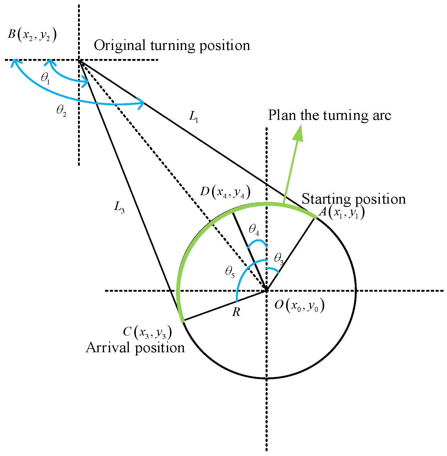
In this paper, an equal-radius circular-arc steering maneuver method is proposed to prevent overshooting or undershooting caused by excessive turning angles. This method will redesign the navigation points and re-plan an optimal turning radius, thereby enabling the ship to turn according to the arc of equal radius. And the newly designed turning radius satisfies the “Harbor Master Design Specification” [18], as shown in Figure 1.
In Figure 1, the original path is A B C , and A D C is the path planned by the equal-radius circular-arc steering maneuver method. When the ship travels to point A, this method will calculate the optimal turning radius. The specific calculation is shown in Equation (1). It is clear from Figure 1 that the planned path A D C sails a shorter distance than the original path A B C , further reducing the voyage time. Meanwhile, the ship can change its course along a smoother path, ensuring that the ship maintains a stable trajectory during the turning process and preventing overshoot caused by an excessive radius. However, due to the large inertia and long-time lag of large ships, a smaller radius may result in too sharp a steering for them.
ω = θ 2 θ 1 L 1 = L 3 = s q r t r 0 / sin ω 2 r 0 2 x 0 = x 2 + r 0 cos θ 1 + θ 2 2 / sin ω + r 0 cos θ 4 y 0 = y 2 + r 0 sin θ 1 + θ 2 2 / sin ω + r 0 sin θ 4 ω θ 3 , θ 5
In the formula, θ 1 represents the initial turning angle when the ship turns from the original path A B to the circular arc path A D C ; θ 2 is the angle between the ship and the arc path during the turning process; θ 3 is the angle between the ship and the arc path during the turning process, which is used to adjust the ship’s heading; θ 4 is the heading angle of the ship when it approaches the end point D of the circular arc path; and θ 5 is the final angle between the vessel and the target path D C after the steering is completed. Equation (2) is the process of calculating the fixed curvature of the ship when it turns, and only three parameters need to be satisfied when planning the path: the turning radius R and the two azimuth angles θ 1 ,   θ 2 . The positional coordinates of the waypoint D can be solved by calculating the angular value of θ 4 . To avoid increasing the computational effort, θ 4 is taken in the range π ,   π . Based on the positional coordinates of the three waypoints of A ,   D ,   C , the positions of the straight lines and arcs can be calculated, and then the positions of θ 4 can be moved sequentially until the entire route is covered.

2.2. Coordinate Conversion

The Freightliner coordinate system is a coordinate system based on the movement characteristics of ships. It can describe the movement of ships more naturally, including heading and position information, etc. Compared with Cartesian coordinates, this coordinate system can reflect the actual motion state of ships more intuitively in the field of ship control and navigation. Therefore, in order to more intuitively reflect the traveling distance and transverse offset of the ship when it is actually sailing, this paper transforms the ship’s Cartesian coordinates into Freightliner coordinates, and it completes path planning under the Freightliner coordinates. Then, the state information under the corresponding Cartesian coordinate system is obtained according to the displacement, transverse distance, and its derivative information. As shown in Figure 2, the centerline of the channel is set as the S axis in the Freightliner coordinate system to describe the ship displacement on the planned route, and the normal vector is set as the l axis to describe the ship yaw [19].
Here, the l axis travels along the route with an increasing S axis and is perpendicular to the reference curve at all times. Equation (2) shows the mapping relationship between the Cartesian coordinate system and the Freightliner coordinates, where x stands for variables in Cartesian coordinates; r stands for variables in Freightliner coordinates; and k r represents the curvature of its trajectory. Equation (3) is the inverse transformation between the two coordinate systems.
S = S r S = v x cos θ x θ r 1 k r l l = s i g n y x y r cos θ r x x x r sin θ r   ·   x x x r 2 + y x y r 2 l = 1 k r l tan θ x θ r
x x = x r l sin θ r y x = y r + l cos θ r θ x = a tan l 1 k r r + θ r         π       , π v x = S 1 k r l 2 + S l 2

2.3. Virtual Ship Group Control Method

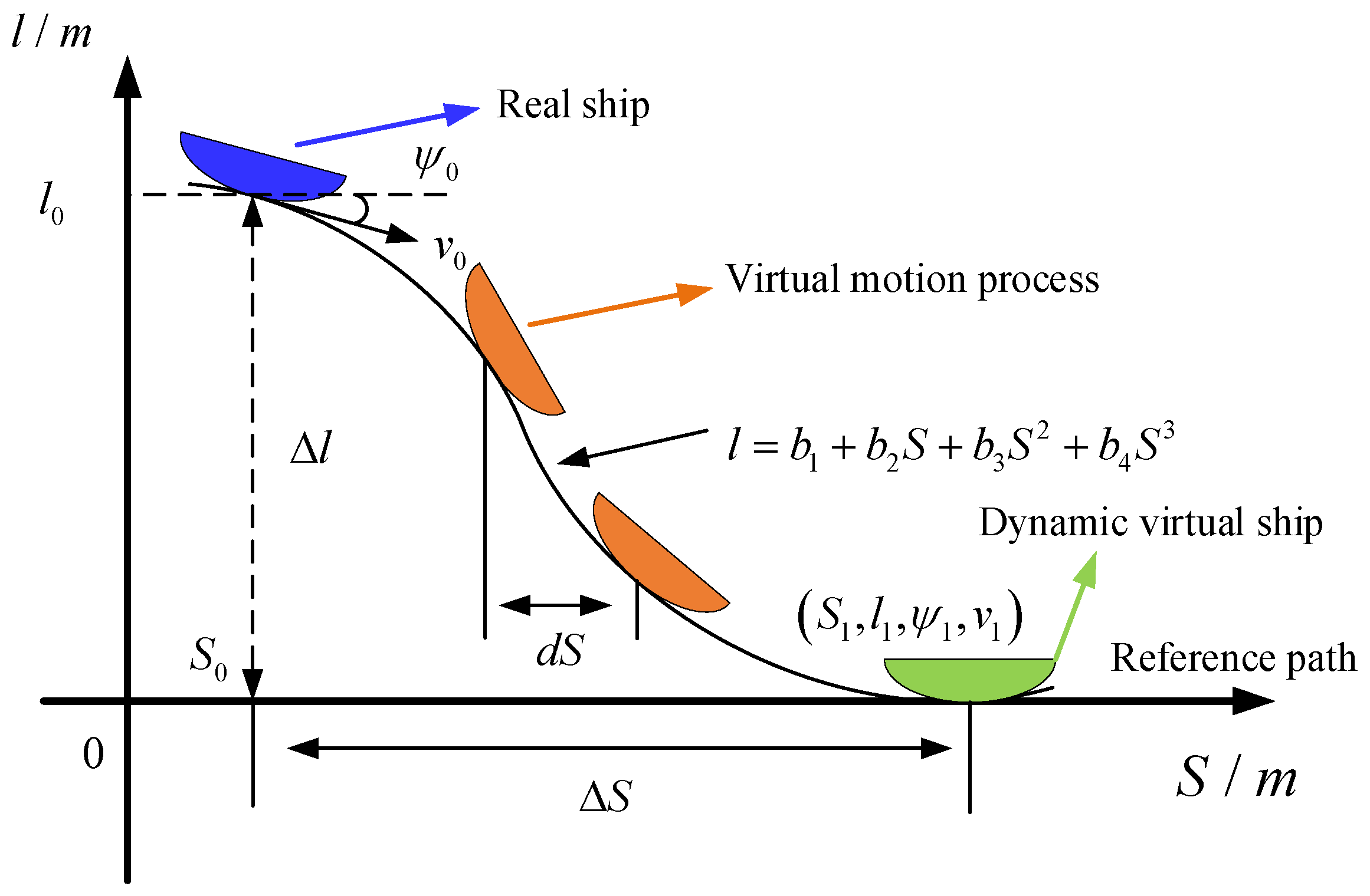
In this section, a virtual ship group control method is proposed to further plan the forward distance as well as the lateral offset of the ship. The virtual ship group is mainly composed of the status of actual ships and the position information of the planned virtual ships. Figure 3 shows the schematic diagram of a dynamic virtual ship group.
This method considers the longitudinal and transverse movements relative to time, respectively, based on the Freiner coordinates, and it calculates the position information of the virtual ship according to the state of the actual ship, then plans the path to be tracked. As shown in Equation (4), the path of the planned virtual ship is l , and it is described using a cubic polynomial.
l = b 1 + b 2 S + b 3 S 2 + b 4 S 3
By substituting the initial state of the actual ship’s position coordinates and the final position information of the dynamic virtual ship, the following relationship can be obtained:
l 0 l 0 l 1 l 1 = 1 S 0 S 0 2 S 0 3 0 1 2 S 0 3 S 0 2 1 S 1 S 1 2 S 1 3 0 1 2 S 1 3 S 1 2 · b 0 b 1 b 2 b 3
where S k = S 0 + k · d S , k is the number of execution steps, and S 0 ,     l 0 and S 1 ,     l 1 represent the Freightliner coordinates of the virtual ship at the beginning and end, respectively. Let l 0                 l 0                 l 1                 l 1 T = G ,     b 0                 b 1                 b 2                 b 3 = K , the intermediate arithmetic process matrix be replaced by L , and Equation (5) be simplified as
K   =   L 1 · G
where L 1 is a pseudo-inverse operation used to prevent singular value problems resulting from special primitive end states. K stands for the coefficient matrix of the polynomial, in which the real ship state is a known condition and the state of the dynamic virtual ship is selected through a continuous optimization process.
In order for the optimized dynamic virtual ship to have the functions of collision avoidance, elimination of transverse offset, and smooth trajectory processing at the same time, and for the collision avoidance function to be prioritized over the other two objectives, this study chooses the dynamic hierarchical weighted function to process the virtual ship state, as shown in Equation (7), where ω 1 > ω 2 > ω 3 .
J = ζ ω 1 J o b s + ω 2 J l + ω 3 J l S
The remaining parameters in the above equation are as follows:
J o b s = max cos θ 0 ± θ p θ k J l = l k / l max l s J K = k r ζ = S c a p < S 0 S S < S r l s S 0 , l 0 S S , l S < d c a p
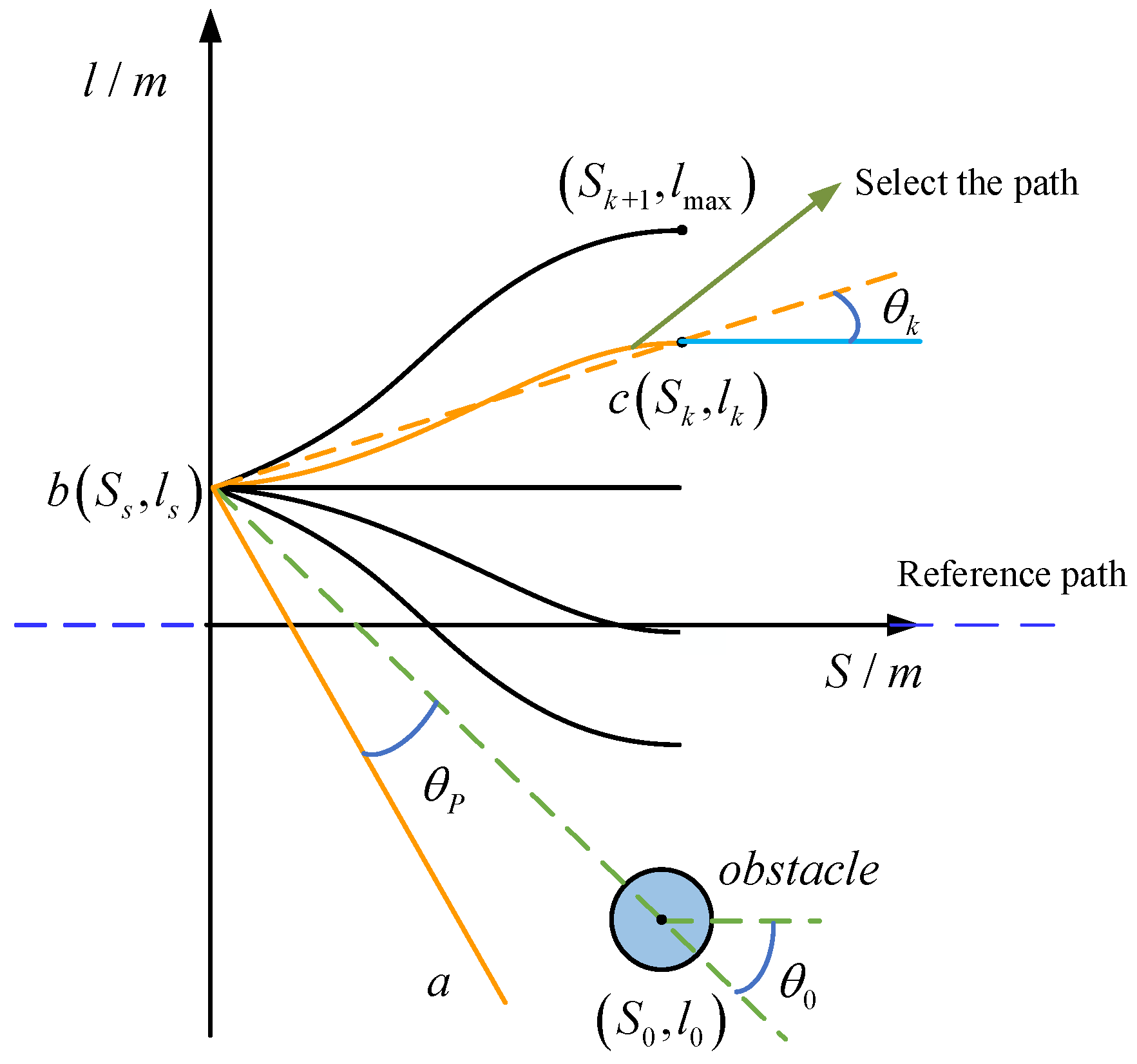
J o b s , J l , and J K are regularized loss variables that impose penalties on heading, yaw, and course curvature toward the obstacle, respectively; ξ is a Boolean variable that determines whether to capture obstacle information based on relative distance; S c a p     stands for capture advance, which refers to the threshold distance at which a ship triggers obstacle avoidance decision preparation when approaching an obstacle, with a set value of 500 m; S r l s stands for release advance, which refers to the threshold distance at which a vessel exits the obstacle avoidance state after avoiding an obstacle and moving away from it (the set value is 100 m); θ k stands for the combined velocity planning direction relative to the obstacle; and θ p is the adjustment angle that keeps the ship away from obstacles. The system is configured with a safety distance of 150 m and an obstacle detection range of 500 m, ensuring an adequate margin for obstacle avoidance. The significance of the relevant parameters is shown in the figure below, where the obstacle velocity is zero.
The blue circle in Figure 4 represents obstacles, and θ k is the planning direction of the synthesized velocity. When the ship travels to the b position, the obstacle enters into the capture distance. The system will generate five path branches based on the obstacles, and then we select the path with the lowest cost as the optimal obstacle avoidance path based on the established performance metrics.
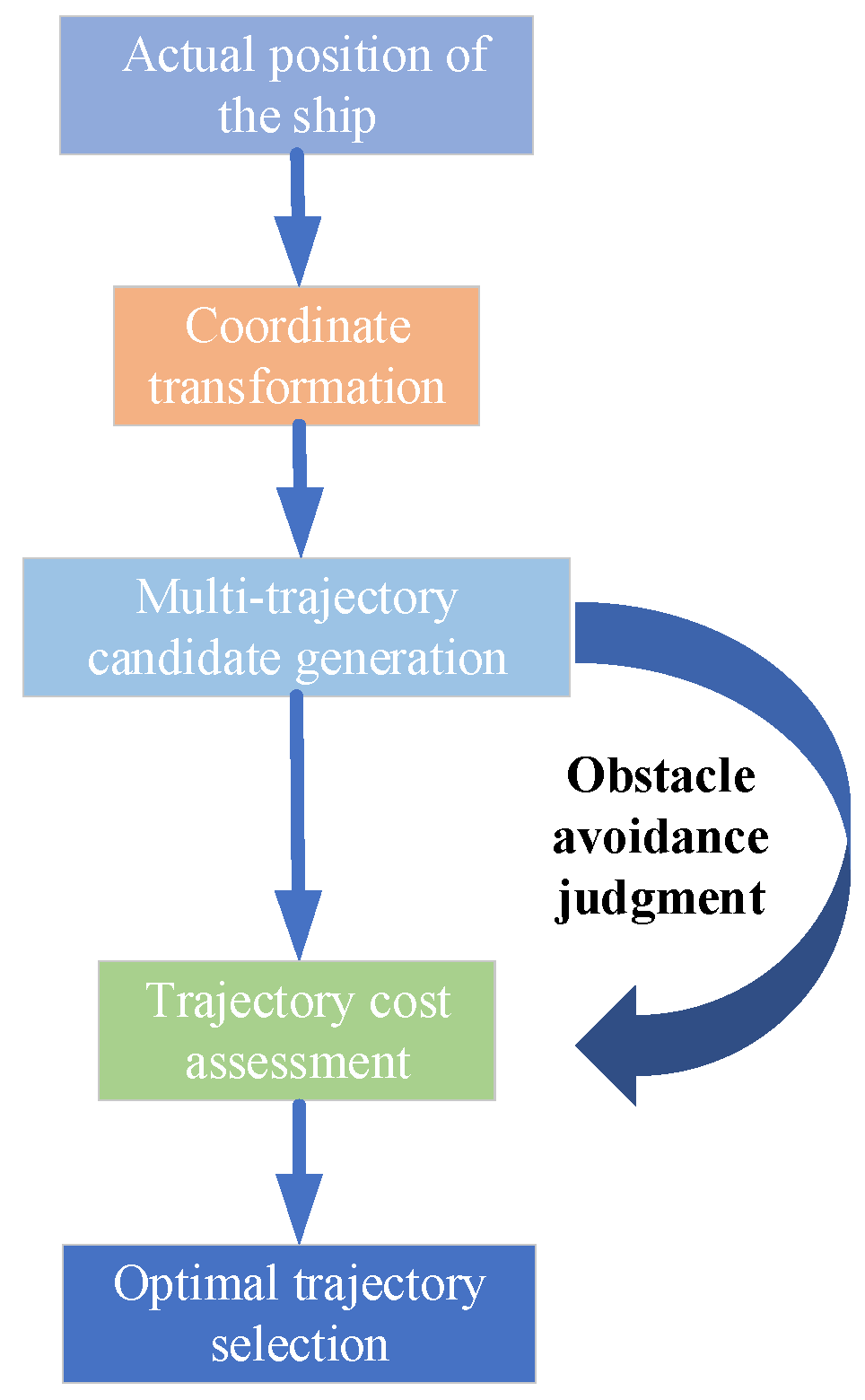
The entire control process revolves around the trajectory tracking and collision avoidance of a ship. Initially, the actual position of the ship is acquired and subjected to coordinate transformation, providing a unified reference for subsequent computations. Based on the position information, multiple candidate navigation trajectories are generated, and a closed loop for obstacle collision-avoidance judgment is introduced simultaneously. If a trajectory is deemed unsafe, it will be regenerated to give priority to collision avoidance and ensure the basic safety of navigation. Subsequently, from the perspectives of navigation efficiency, control cost, and path-tracking accuracy, a cost assessment is conducted on the safe trajectories. Ultimately, in accordance with the assessment results, the trajectory with the optimal comprehensive performance is selected as the navigation instruction for the actual execution of the ship, enabling the ship to navigate safely and efficiently in complex environments. The entire control process is illustrated in Figure 5.

3. Model Predictive Control Scheme

The Nomoto model is applicable to the approximate description of the motion characteristics of ships and can be used for the dynamic response simulation of path-tracking control [20]. Therefore, this paper selects the Nomoto ship motion model for further research. The model is constructed as shown in Equation (9):
G s = φ s δ s = K 0 s T 0 s + 1
where G s stands for the transfer function mathematical model, and φ ,     δ represents the ship range and rudder angle. MPC is a discrete model-based control method, and to reduce the computational effort of subsequent constraintization, Equation (9) needs to be discretized into a differential, integrated, moving-average autoregressive (CARIMA) model, which then captures most of the properties of the transfer function model. This paper takes the “Yukun” ship as the research object, and it discretizes its Nomoto mathematical model to obtain the CARIMA mathematical model as follows:
b z φ k = c z δ k + T f z Δ z ξ k
in which b z = b 1 z 1 + + b m z m , c z = c 1 z 1 + + c m z m , φ k is the bow output of the k step, δ k is the rudder angle of the k step, ξ k denotes the unknown zero-mean value of the environmental interference and measurement noise, Δ z = 1 z 1 stands for the difference operator, and T f z is the filter, which is the mechanism for adjusting the sensitivity of the loop about ξ k . Its specific value is T f z = 1 ,     0.2 .
If the noise and interference are well suppressed by the compensation mechanism, let A z = a z     Δ z , expanding a z     Δ z     φ z = b z Δ δ z (as an example of expanding by 4 steps), which yields
φ k + 1 + A 1 φ k + + A n φ k n + 1 = b 1 Δ δ k + b 2 Δ δ k 1 + + b m Δ δ k m + 1 φ k + 2 + A 1 φ k + 1 + + A n φ k n + 2 = b 1 Δ δ k + 1 + b 2 Δ δ k + + b m Δ δ k m + 2 φ k + 3 + A 1 φ k + 2 + + A n φ k n + 3 = b 1 Δ δ k + 2 + b 2 Δ δ k + 1 + + b m Δ δ k m + 3 φ k + 4 + A 1 φ k + 3 + + A n φ k n + 4 = b 1 Δ δ k + 3 + b 2 Δ δ k + 2 + + b m Δ δ k m + 4
The above equation can be organized as
C A φ k + 1 = C b Δ δ k + H b Δ δ k 1 H A φ k
in which and represent the predicted time-domain variables and past variables, respectively, C A and C B represent the A z and b z Toplitz matrices, respectively, and H A and H B are the Hankel matrices for A z and b z , respectively.
C A = 1 0 0 0 A 1 1 0 0 A 2 A 1 1 0 A 3 A 2 A 1 1 ,   C B = b 1 0 0 0 b 2 b 1 0 0 b 3 b 2 b 1 0 b 4 b 3 b 2 b 1 H A = A 1 A 2 A n 4 A n 3 A n 1 A n A 2 A 3 A n 3 A n 2 A n 0 A 3 A 4 A n 2 A n 1 0 0 A 4 A 5 A n 1 A n 3 0 0 H b = b 2 b 3 b m 4 b m 3 b m 1 b m b 3 b 4 b m 3 b m 2 b m 0 b 4 b 5 b m 2 b m 1 0 0 b 5 b 6 b m 1 b m 0 0
To further enhance the control accuracy of the system, the Extended Kalman Filter (EKF) algorithm is added to the control system. EKF takes the current state estimation of the MPC algorithm as the control input. By constantly updating the state estimation, it predicts the state at the next moment, thereby estimating the state of the ship more accurately. Equation (14) shows the state prediction step of the EKF algorithm at moment k :
x k | k 1 = f x k 1   , u k 1 P k | k 1 = A k P k 1 A k T + Q k
in which x k | k 1 stands for the state prediction value at the moment k ; A k is the state transfer Jacobi matrix; P k | k 1 is the prediction covariance matrix; and Q k is the process noise covariance matrix. Among them, the Q k matrix is shown as Equation (15).
Q k = q x 0 0 0 0 0 q y 0 0 0 0 0 q v 0 0 0 0 0 q θ 0 0 0 0 0 q r
where q x , q y , q v , q θ , and q r denote the process noise variance of position x , position y , velocity v , heading angle θ , and yaw rate r , respectively.
The EKF algorithm performs a state update step after predicting the state in the next moment, taking into account the actual measured data as well as the predicted state. Equation (16) shows the state update step of the EKF algorithm at moment k :
y k = z k h x k | k 1 S k = H k P k | k 1 H k T + R k K k = P k | k 1 H k T S k 1 x k = x k | k 1 + K k y k P k = I K k H k P k | k 1
in which y k stands for the measurement residual; H k stands for the measurement Jacobi matrix; S k stands for the measurement covariance matrix; K k stands for the Kalman gain; and R k stands for the measurement noise covariance matrix, as shown in Equation (17).
R k = r x 0 0 0 0 0 r y 0 0 0 0 0 r v 0 0 0 0 0 r θ 0 0 0 0 0 r r
where r x , r y , r v , r θ , and r r denote the measurement noise variance of position x , position y , velocity v , heading angle θ , and yaw rate r , respectively.
The EKF algorithm feeds the computed state estimates back into the MPC algorithm again to further update the state variables of the MPC algorithm. This step ensures that the state variables of the MPC are always the estimated values corrected by the EKF, thus enhancing the accuracy and robustness of the system. Equation (18) represents the latest bow output at the moment of k + 1 , where E = C A 1 C b ;   F = C A 1 H b ; and G = C A 1 H A .
φ k + 1 = E Δ δ k + F Δ δ k 1 G φ k
In the control system, the state error is the error between the current state and the expected state, which is utilized to measure the tracking performance of the system. Its specific calculation is shown in Equation (19), where φ r e f ,       k + 1 represents the expected output of the system at the k + 1 moment, and φ k + 1 represents the predicted output at the k moment.
e k + 1 = φ r e f ,       k + 1 φ k + 1
Establish the following quadratic indicators:
J = e k + 1 T e k + 1 + λ Δ δ k T                   = φ r e f ,     k + 1 T φ k + 1 T φ r e f ,     k + 1 φ k + 1 + λ Δ δ k T Δ δ k
where Δ δ k is the rudder angle change at the k step. Among them, λ is a regularization parameter used to balance the state error and control the energy of the input. When substituting φ k + 1 in Equation (18), the following can be obtained:
J = φ r e f ,     k + 1 T F Δ δ k 1 T G φ k T φ r e f ,     k + 1 F Δ δ k 1 G φ k + E Δ δ k T E Δ δ k                                   2 E Δ δ k T φ r e f ,     k + 1 F Δ δ k 1 + G φ k + λ Δ δ k T Δ δ k
By analyzing the above equation, it can be concluded that only the terms related to Δ δ k are operable in the control. Therefore, the optimization problem can be established as
f Δ δ k = Δ δ k T H T H + λ I Δ δ k Δ δ k T 2 H T R k + 1 F Δ δ k 1 G φ k Δ δ k = arg min f Δ δ k s . t .       M Δ δ d z
in which M stands for the selection matrix of the predictor variables, and d z is the constant matrix containing the upper- and lower-bound constraints Δ δ ¯ and Δ δ ¯ . The above equation is a quadratic programming issue, and the result can be addressed based on the interior point method encapsulated in MATLAB R2023b.
Assume that there exists a feasible optimal control sequence δ 0 , δ 1 , δ 2 , , δ n 2 , 0 in the initial state φ 0 , corresponding to the state response sequence φ 0 , φ 1 , φ 2 , , φ n . Therefore, the corresponding control term of this control sequence δ 0 , δ 1 , δ 2 , , δ n 2 , 0 continues to be used at φ 1 , resulting in e n = R n φ n = 0 . The optimal performance indicators at the initial moment and the optimal performance indicators at the next moment are shown in Equation (23).
J 0 = min δ 0 i = 0 n 1 e i 2 + λ 1 Δ δ i 2 J 1 = min δ 0 i = 1 n e i 2 + λ 1 Δ δ i 2 = i = 0 n 1 e i 2 + λ 1 Δ δ i 2 e 0 2 + λ 1 Δ δ i 2 + e n 2 + λ 1 Δ δ n 2
By comparing these two performance indicators, it can be obtained that
J 1 J 0 = e 0 2 + λ 1 Δ δ 0 2 + e n 2 + λ 1 Δ δ 0 2 < 0 .
From the above formula, it can be seen that the performance indicators of the system monotonically decrease, thereby proving the stability of the system.
Summary of this section: In the actual navigation process of a ship, its real-state information is input into the Extended Kalman Filter (EKF) module. Through state prediction and update steps, environmental disturbances and measurement noises are filtered out, thereby obtaining optimized state estimates. The state estimates corrected by the EKF are used as inputs to the model predictive control (MPC). Combined with the discretized CARIMA ship model, a sequence of future states is generated within the prediction horizon. Subsequently, MPC solves the optimal control sequence based on state errors and a quadratic cost function, and it outputs the first-step rudder angle command to act on the ship. The new state of the ship after executing the control command is fed back to the EKF again, forming a closed-loop data flow of “measurement—filtering—prediction—control”, which ultimately achieves high-precision trajectory tracking and improved robustness. This data flow architecture, through the dynamic coupling of EKF and MPC, not only ensures the accuracy of state estimation but also enhances the adaptability of control decisions to model errors and external disturbances.
Remark 2. 
Incorporating the EKF algorithm into the MPC algorithm can realize the function of fast real-time updating of the ship state estimation, which enables the system to respond to the changes in the ship state in a timely manner, and it ensures the maneuverability of the ship as well as the safety of navigation in the complex environment.

4. Experimental Simulation

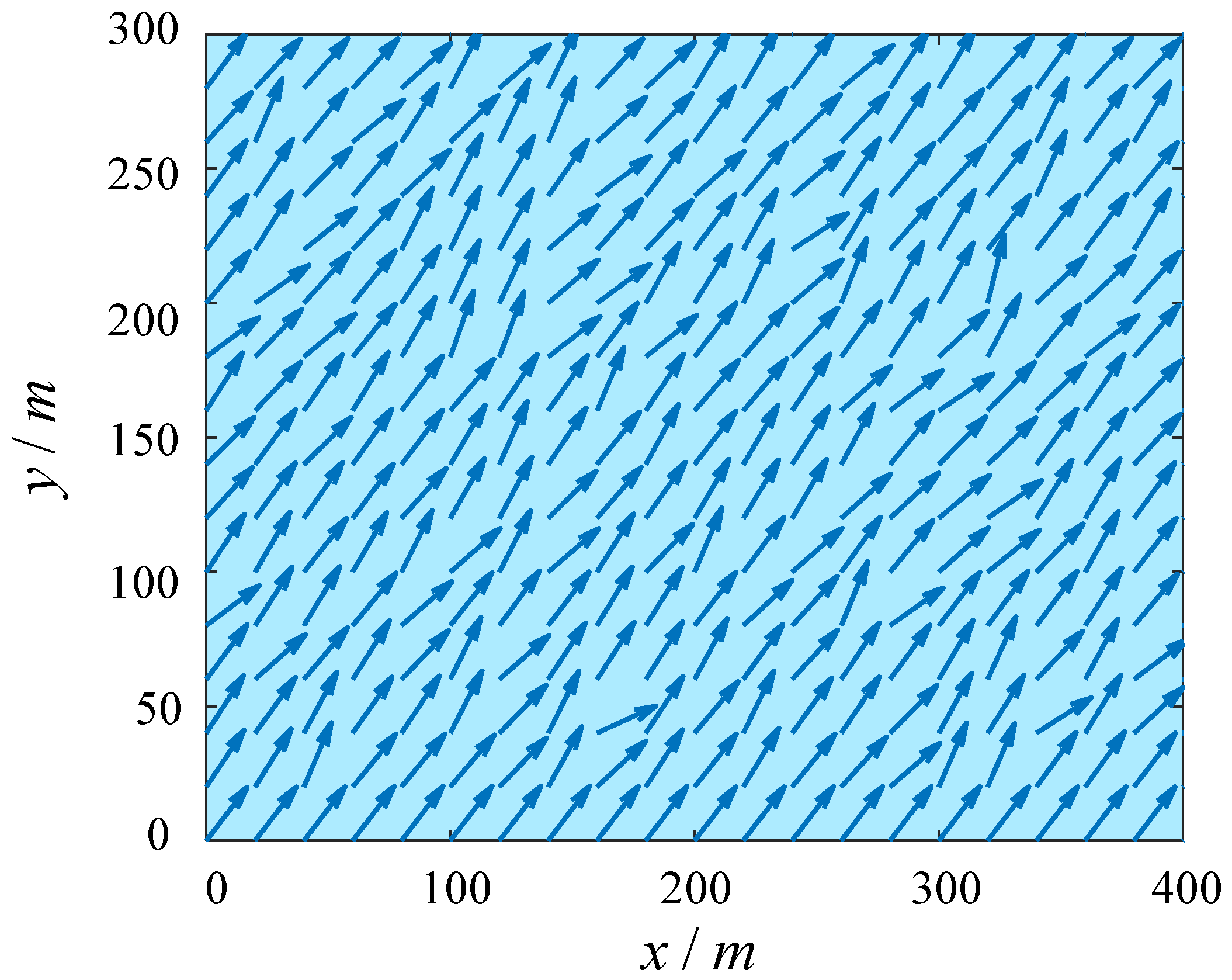
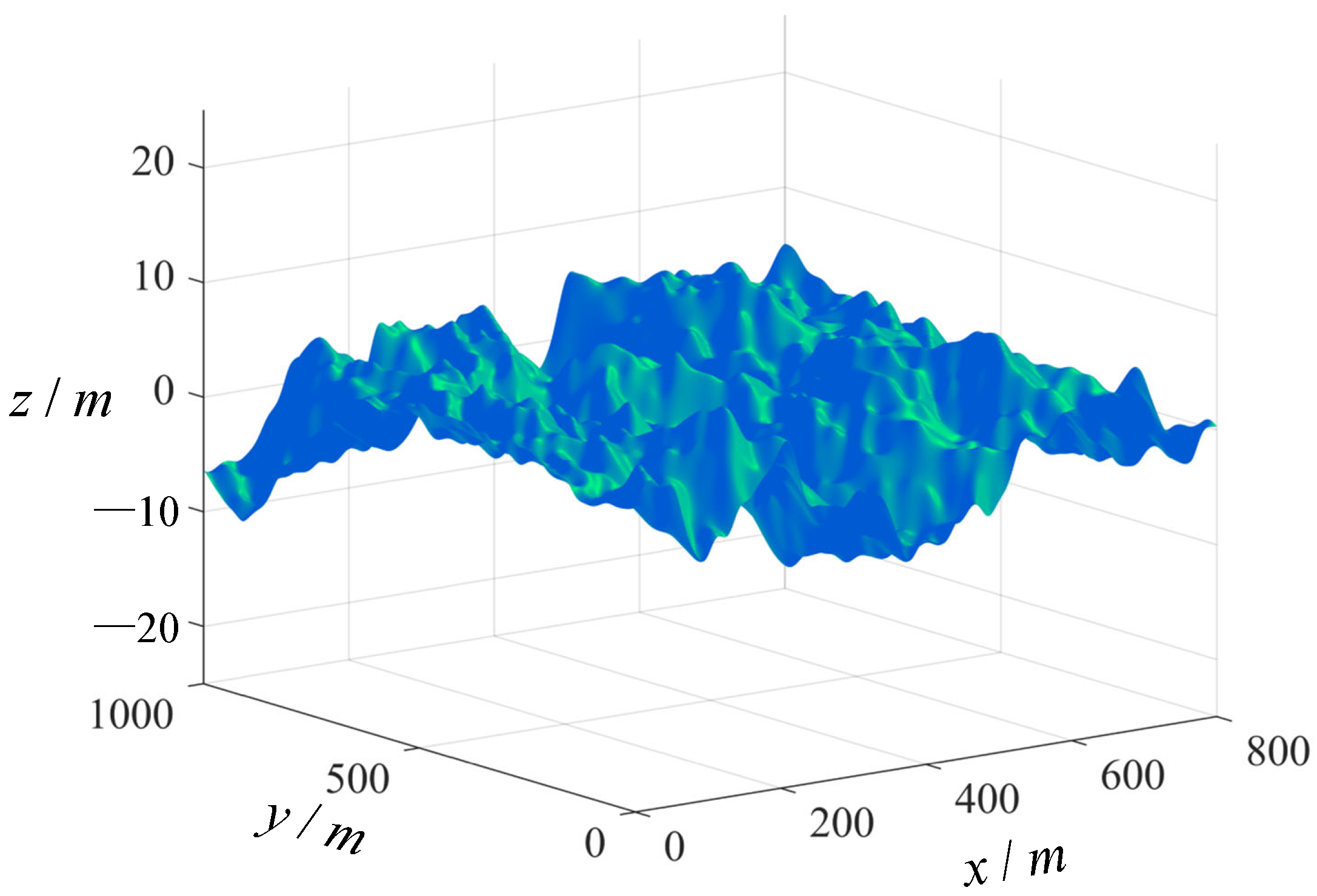
To verify the anti-interference of the control method proposed, level 6 wind and wave disturbances are included in the simulation experiments. Figure 6 and Figure 7 are the simulation result diagrams of the wind field and wave field introduced in this experiment [21]. The direction of the blue arrow in Figure 6 indicates the flow direction of the wind. The parameters of this wind farm are set as follows: average wind speed 10 m/s, wind direction angle 30°. The wave field parameters are as follows: The effective wave height is approximately 2.5 m, the wave period is between 6 and 10 s, and the wave direction is random. The wave spectrum adopts the Pierson–Moskowitz model, in which the peak frequency of the spectrum is 0.1 Hz and the spectrum width is 0.05 Hz.
This experiment takes the “Yukun” ship as the research object to carry out simulation experiments. The specific parameters of the model are shown in the following Table 2 [22].
This paper adopts the Legion R7000 ARP8 device for simulation experiments. The processor of this device is “AMD Ryzen 7 7735H with Radeon Graphics 3.20 GHz”. The simulation software used is MATLAB R2023b.
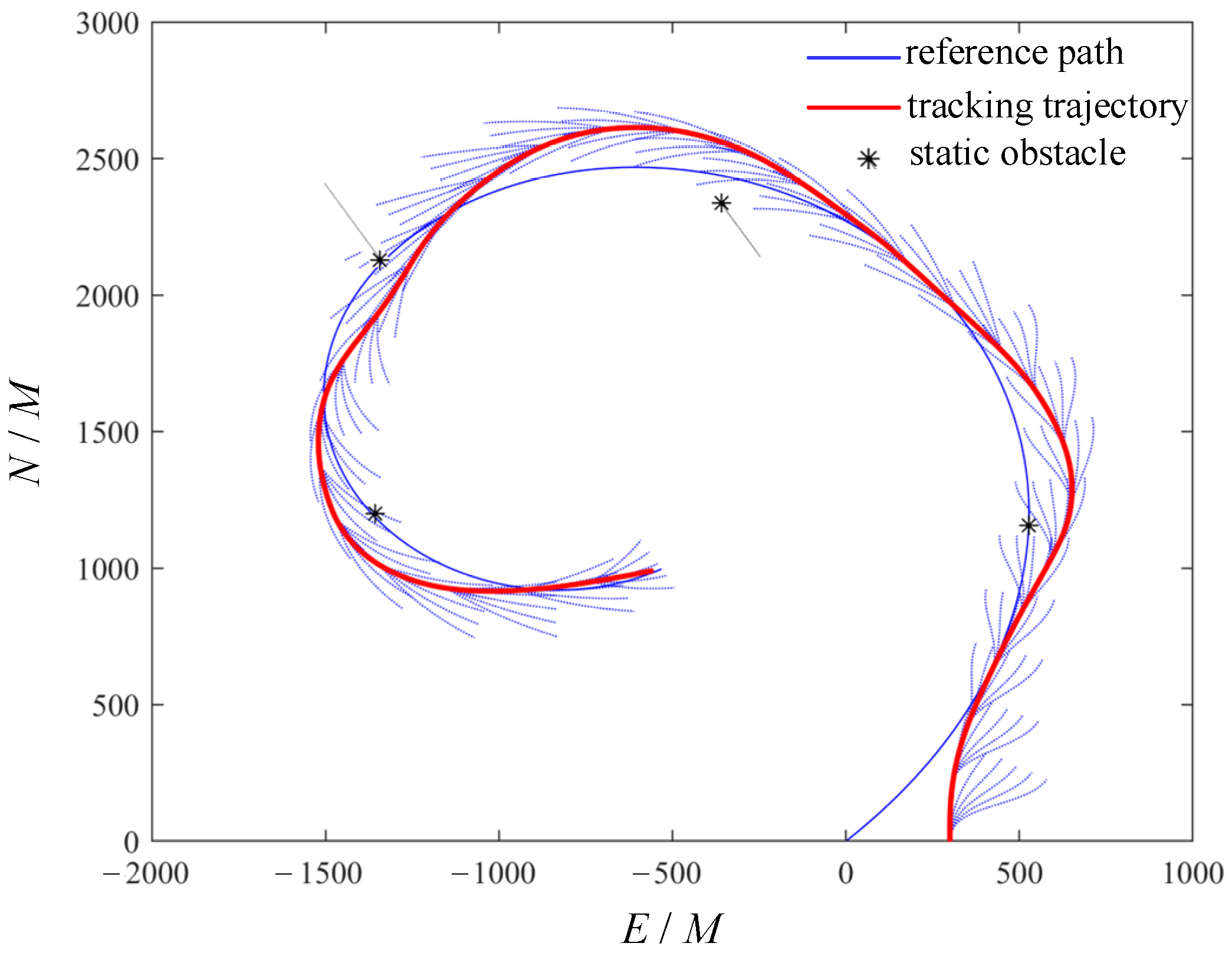
In this experiment, a reference path is generated using the cubic spiral curve function, and static obstacles as well as dynamic obstacles are added to the path to further validate the algorithm’s obstacle avoidance function in complex environments. The obstacle avoidance effect is shown in Figure 8. The star points represent the obstacles, and the star points with moving trajectories represent the dynamic obstacles. The position information of the four obstacles a, b, c, and d in sequence is [810, 2516, 0, 0], [−700, 3800, 0.75, 120 * pi/180], [−2500, 4000, 0.4300 * pi/180], and [−2163, 2000, 0, 0]. The first two elements represent the initial horizontal and vertical coordinates of the obstacle, and the last two elements represent the speed and direction of the obstacle. The blue line represents the original planned route, the red represents the tracking trajectory, and the dashed lines represent the planned path branches. This experiment was set up with a ship speed of 13 knots and a sampling rate of 1 Hz.
The system causes the ship to perform approach behavior and perform tracking functions based on a reference path. While traveling, when the system detects an obstacle entering the capture distance, it can pre-generate five path branches based on the location of the obstacle. And a cost function is calculated for each obstacle with respect to the real-time position of the ship, which is added to the total planning cost. Subsequently, the system selects one of the paths with the smallest total cost as the optimal obstacle avoidance path. And so on until the ship reaches the final position of the target reference path.
From the above figure, it can be seen that the ship model can still safely avoid obstacles and travel normally under the interference of 6 level wind and waves. And it can execute a trajectory-tracking decision quickly after successful obstacle avoidance, close to the original reference path.
As shown in Figure 9, the rudder angle output of the algorithm proposed in this paper is plotted when performing trajectory tracking as well as obstacle avoidance tasks, where the red line represents the rudder angle output value of the original MPC algorithm, the green line represents the rudder angle output value of the nonlinear feedback control algorithm, pink represents the rudder angle output graph of the Line of-Sight method, and the blue line represents the rudder angle output value of the improved MPC. It can be clearly seen from the above figure that the improved model predictive control algorithm, compared with the other two algorithms, not only accurately completes the track tracking and obstacle avoidance tasks but also further reduces the motion amplitude of the ship model, avoiding problems such as energy loss and mechanical wear caused by an excessive output rudder angle. Table 3 shows a comparison of rudder angle outputs between the original MPC algorithm and the improved MPC algorithm under sea conditions of level 6. Compared with the nonlinear feedback control algorithm, the improved MPC algorithm reduces the maximum rudder angle output value by 58%, the integral absolute error by 34%, and the root mean square error value by 36%. Compared with the Line-of-Sight (LOS) algorithm, the improved MPC algorithm still has a better control performance. The maximum rudder angle output value was reduced by 32%, the integral absolute error was reduced by 45%, and the root mean square error was reduced by 48%. Compared with the original MPC algorithm, the improved MPC algorithm reduces the maximum rudder angle output value by 58%, the integral absolute error by 46%, and the root mean square error value by 46%. Thus, the algorithm suggested in this paper can ensure that the ship accurately performs the trajectory tracking and obstacle avoidance tasks under adverse sea conditions, as well as further reduce mechanical wear and tear.
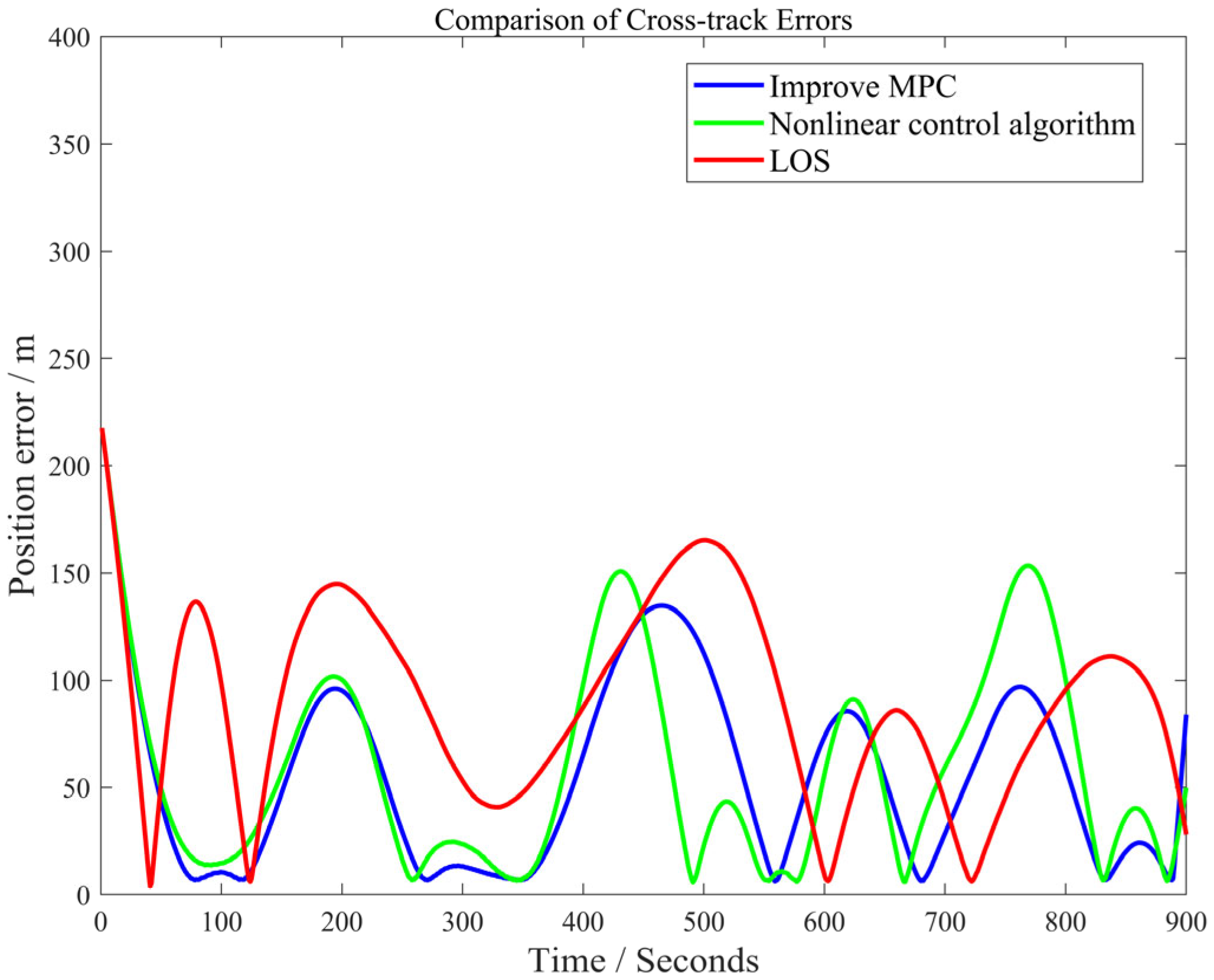
To further analyze the tracking performance of the algorithm proposed in this paper and the nonlinear feedback control algorithm, Figure 9 presents the convergence curves of position errors under the two control laws. The calculation of the position tracking error is shown in Equation (25).
d = x a c t x r e f 2 + y a c t y r e f 2
As can be seen from Figure 10, compared with the nonlinear control algorithm and the LOS algorithm, the position error under the improved MPC control law is smaller and can effectively track the reference path. Meanwhile, the improved MPC control law has a relatively fast convergence speed, which can respond promptly and adjust the control input to reduce offset.
To ensure the statistical reliability of the experimental results, this paper conducted 10 independent repeated tests for the same scenario (including sea conditions of level 6). The final result shows a high degree of consistency. Therefore, the proposed algorithm has a stable performance in complex sea conditions and the results are reproducible.
This subsection verifies the validity of the proposed method through the above simulation experiments, while all the verifications are carried out in the simulation environment. In the future, an experimental platform will be set up to test the hardware and validate the proposed method in real scenarios using the Yukun ship as the experimental object.

5. Conclusions

To solve the overshoot problem caused by an excessive turning radius when ships turn, an equal-radius-arc turning maneuver method is proposed. Based on the model predictive control algorithm, a virtual ship group control method was proposed, and a hierarchical weighting function was established to process the state information of virtual ships, thereby effectively implementing collision avoidance decisions. Meanwhile, the Extended Kalman Filtering algorithm is introduced. By continuously performing the prediction and update steps, the control accuracy of the system is further improved. It can be seen from the simulation results that the method proposed in this paper can still accurately perform the tracking task and safely avoid obstacles under the interference of wind waves of level 6, and it has a strong anti-interference ability and obstacle avoidance function. While ensuring safe operation, we must further reduce the rudder angle output value to avoid excessive energy consumption and mechanical wear problems.
Subsequently, the author will integrate real sensors to verify the performance of complex, dynamic-obstacle recognition and obstacle avoidance, and conduct real-ship experiments on the “Yukun” vessel to verify the stability of the steering control method and the real-time performance of the control strategy, as well as the adaptability of the extended algorithm in high-flow waters.
Author Contributions

Conceptualization, C.S.; methodology, C.S.; software, C.S.; validation, C.S. and J.S.; formal analysis, Q.Q.; investigation, Q.Q.; resources, J.S. and C.S.; data curation, Q.Q.; writing—original draft preparation, C.S. and Q.Q.; writing—review and editing, C.S. and Q.Q.; visualization, C.S.; supervision, J.S.; project administration, J.S.; funding acquisition, J.S. All authors have read and agreed to the published version of the manuscript.

Funding

This study was funded by the Liaoning Provincial Department of Education’s Basic Scientific Research Project for Colleges and Universities in 2023 (JYTQN2023131), the Liaoning Provincial Science and Technology Plan (600024003), Dalian Youth Science and Technology Star Project in 2024 and Joint Program Project of Science and Technology Plan of Liaoning Province.

Data Availability Statement

The data presented in this study are available upon request from the corresponding author.

Conflicts of Interest

The authors declare no conflicts of interest.

References

  1. Ma, W.; Chang, X.; Sun, S.; Xiao, Y. Numerical research on the effect of brackets installation angle on the propeller wake field and propulsion performance in a four-screw ship. Ocean Eng. 2022, 266, 112303. [Google Scholar] [CrossRef]
  2. Song, C.; Li, Y.; Sui, J.; Zhang, X. Nonlinear innovation identification algorithm based on comprehensive application method for large ship model in rough sea. Ocean Eng. 2024, 303, 117502. [Google Scholar] [CrossRef]
  3. Ma, W.; Chang, X.; Wang, W.; Sun, S.; Qiu, Y. Study on the influence of shaft brackets on the scale effect of the four-screw ship wake field. Ocean Eng. 2023, 287, 115881. [Google Scholar] [CrossRef]
  4. Wang, S.; Sun, M.; Xu, Y.; Liu, J.; Sun, C. Predictor-based fixed-time LOS path following control of underactuated USV with unknown disturbances. IEEE Trans. Intell. Veh. 2023, 8, 2088–2096. [Google Scholar] [CrossRef]
  5. Yang, Z.; Liu, F.; Wang, Y. Neural sliding mode control for underactuated ship path tracking. Shipbuild. China 2015, 56, 45–55. [Google Scholar] [CrossRef]
  6. Zhu, P.; Zhuang, J.; Zhang, L.; Su, Y.; Yuan, Z. Path tracking of underactuated unmanned vessels based on the improved line-of-sight method. J. Harbin Eng. Univ. 2020, 41, 784–791. [Google Scholar] [CrossRef]
  7. Wang, M.; Su, Y.; Wu, N.; Fan, Y.; Qi, J.; Wang, Y.; Feng, Z. Vector field-based integral LOS path following and target tracking for underactuated unmanned surface vehicle. Ocean Eng. 2023, 285, 115462. [Google Scholar] [CrossRef]
  8. Tan, C.; Du, J.; Xu, G.; Li, D. Trajectory tracking control design of underactuated surface vehicless based on ESO and dynamic inversion. Ship Eng. 2020, 42, 103–109. [Google Scholar] [CrossRef]
  9. Qin, J.; Du, J.; Li, J. Output redefinition dynamic inverse trajectory tracking control of underactuated surface vessels with external disturbance. In Proceedings of the 2019 3rd International Symposium on Autonomous Systems (ISAS), Shanghai, China, 29–31 May 2019; pp. 400–405. [Google Scholar] [CrossRef]
  10. Song, C.; Zhang, X.; Zhang, G. Nonlinear identification for 4-DOF ship maneuvering modeling via full-scale trial data. IEEE Trans. Ind. Electron. 2021, 69, 1829–1835. [Google Scholar] [CrossRef]
  11. Zhou, Y.; Gong, C.; Chen, K. Adaptive control scheme for USV Trajectory-Tracking under complex environmental disturbances via deep reinforcement learning. IEEE Internet Things J. 2025, 12, 15181–15196. [Google Scholar] [CrossRef]
  12. Wang, Q.; Zhang, Q.; Wang, Y.; Hu, Y.; Guo, S. Event-triggered adaptive finite time trajectory tracking control for an underactuated vessel considering unknown time-varying disturbances. Transp. Saf. Environ. 2023, 5, tdac078. [Google Scholar] [CrossRef]
  13. Li, H.; Meng, X.; Zhang, Q.; Wu, H.; Wang, C.; Li, X. Finite-Time tracking control of underactuated surface vessels with disturbance compensation. In Proceedings of the International Conference on Guidance, Navigation and Control, Harbin, China, 5–7 August 2022; Springer Nature: Singapore, 2022; pp. 1695–1705. [Google Scholar] [CrossRef]
  14. Zeng, D.; Cai, C. Finite-time trajectory tracking control of surface ships based on the exponentiation integral method. Ship Boat 2024, 35, 9–18. [Google Scholar] [CrossRef]
  15. Shen, Z.; Bi, Y.; Wang, Y.; Guo, C. Adaptive recursive sliding mode control for trajectory tracking of input-output restricted ships. Control Theory Appl. 2020, 37, 1419–1427. [Google Scholar] [CrossRef]
  16. Zhang, C.; Wang, C.; Cao, W.; Wang, J. Underactuated USV neural network adaptive trajectory tracking control. J. Harbin Inst. Technol. 2020, 52, 1–7. [Google Scholar] [CrossRef]
  17. Zhang, G.; Li, J.; Jin, X.; Cheng, L. Robust adaptive neural control for wing sail assisted vehicle via the multiport event-triggered approach. IEEE Trans. Cybern. 2022, 52, 12916–12928. [Google Scholar] [CrossRef] [PubMed]
  18. Hua, L.; Hongchao, L. Discussion on the Design Method of Channel Turning Sections. Port Eng. Technol. 2020, 57, 22–25. [Google Scholar] [CrossRef]
  19. Yoon, S.; Kwon, Y.; Ryu, J.; Kim, S.; Choi, S.; Lee, K. Reinforcement-learning-based trajectory learning in frenet frame for autonomous driving. Appl. Sci. 2024, 14, 6977. [Google Scholar] [CrossRef]
  20. Han, X.; Zhang, X. Tracking control of ship at sea based on MPC with virtual ship bunch under Frenet frame. Ocean Eng. 2022, 247, 110737. [Google Scholar] [CrossRef]
  21. Song, C.; Guo, T.-E.; Sui, J.-H. Fishing ship trajectory tracking control based on the closed-loop gain shaping algorithm under rough sea. China Ocean Eng. 2025, 39, 365–372. [Google Scholar] [CrossRef]
  22. Zhang, X.; Zhang, G. Nonlinear Feedback Theory and Its Application in Ship Motion Control; Dalian Maritime University Press: Dalian, China, 2020. [Google Scholar]
Figure 1. Schematic diagram of equal-radius circular-arc steering maneuver.
Jmse 13 01603 g001
Figure 2. Cartesian coordinate system and Freightliner coordinates.
Jmse 13 01603 g002
Figure 3. Schematic diagram of dynamic virtual ship group control.
Jmse 13 01603 g003
Figure 4. Selection of optimal path based on performance metrics.
Jmse 13 01603 g004
Figure 5. Control flow chart.
Jmse 13 01603 g005
Figure 6. Wind field used for simulation.
Jmse 13 01603 g006
Figure 7. Wave field used for simulation.
Jmse 13 01603 g007
Figure 8. Obstacle avoidance effect diagram.
Jmse 13 01603 g008
Figure 9. Comparison of output rudder angle.
Jmse 13 01603 g009
Figure 10. Position error convergence curve.
Jmse 13 01603 g010
Table 1. Analysis table.
Control MethodAnalysis
Traditional Line-of-Sight (LOS)The tracking accuracy for nonlinear paths is relatively low, and it is difficult to handle scenarios with large curvature turns.
LOS + PID controlThe lack of an active compensation mechanism for disturbances leaves the dynamic tracking performance vulnerable to external factors.
Expanded observer + dynamic inverse controlThe performance of the observer depends on the accuracy of the model, and its suppression effect on unmodeled dynamics and strong disturbances is limited.
Event-triggered sliding mode controlSliding mode control has chattering phenomena, which can easily lead to frequent actions of the actuator.
Conventional model predictive control (MPC)The computational complexity increases exponentially with the growth of the prediction time domain, and the real-time performance is limited.
Table 2. Hydrodynamic parameters of the “Yukun” vessel.
ParameterValueParameterValue
X uu 3.56556 N v −0.0999
X vv −0.0697 N r −0.0455
X vr −0.0481 N rr −0.0339
X rr 0.0292 N vrr −0.0561
Y v −0.3032 N vvr −0.1822
Y r 0.0832 N φ −0.0076
Y vv −0.7834 N −0.1718
Y rr −0.0543 N 0.01073
Y vr −0.2099
Table 3. Comparison of performance in class 6 sea state.
Maximum Rudder Angle Output Value/°IAERMSE
Improved MPC151614.90
Nonlinear feedback algorithm362457.63
Improvement rate compared to improved MPC58%34%36%
Original MPC262979.11
Improvement rate compared to improved MPC58%46%46%
Line of Sight222949.45
Improvement rate compared to improved MPC32%45%48%
Disclaimer/Publisher’s Note: The statements, opinions and data contained in all publications are solely those of the individual author(s) and contributor(s) and not of MDPI and/or the editor(s). MDPI and/or the editor(s) disclaim responsibility for any injury to people or property resulting from any ideas, methods, instructions or products referred to in the content.