1. Introduction
The erosion of turbine blades in tidal stream environments is a significant challenge due to suspended abrasive particles (sand/sediment) in the flow. Repeated impacts by these particles on blade surfaces can remove material over time, leading to surface roughness, efficiency loss, and structural damage. Composite materials are increasingly used for tidal turbine blades because of their high strength-to-weight ratio and corrosion resistance. In particular, FR4 (a fibreglass-reinforced epoxy composite) is a relevant material, as it is a glass fibre-reinforced polymer (GFRP) known for good mechanical properties and water resistance. FR4 and similar GFRP composites are considered viable for marine energy applications, but their durability under solid particle erosion is not well established. Thus, understanding and predicting the erosion of FR4 in tidal conditions is critical for reliable turbine design.
Erosion is primarily governed by two mechanisms: cutting wear, dominant at shallow impact angles, and deformation wear, which prevails at steeper angles. Bitter first distinguished these mechanisms in his two-part study [
1,
2], showing that ductile and brittle materials respond differently to particle impacts. Ductile metals typically show maximum erosion near 30–45°, while brittle materials peak around 90°. This dual mechanism framework continues to underpin modern erosion modelling.
Finnie, Archard, and Neilson–Gilchrist contributed to early wear models that relate erosion rate to particle velocity, angle, and material hardness. However, these were predominantly designed for homogeneous, ductile targets. Among modern approaches, the empirical model proposed by Oka et al. [
3,
4] is widely used for its predictive flexibility and widespread adoption. It incorporates impact velocity, angle, particle size, and target material hardness in a power-law format. Though originally calibrated for ductile metals, its structure is fundamentally empirical and allows for adaptation to other materials if suitable experimental data is available. Despite this, no calibrated Oka coefficients currently exist for composite materials like FR4, nor has a methodology been proposed to connect such erosion modelling to performance prediction in marine systems.
Numerous experimental studies have explored erosion in polymer matrix composites. Stack et al. [
5] studied the erosion of GFRP across various angles and velocities, revealing matrix cracking, fibre pull-out, and delamination modes that are absent in metals. Biswas et al. [
6] and Wood [
7] reviewed composite erosion more broadly, emphasising the impact of environmental exposure, fibre architecture, and particle characteristics. However, these efforts have not produced predictive erosion equations analogous to Oka’s.
In the oil and gas sector, Shirazi, McLaury, and Arabnejad developed semi-mechanistic erosion models calibrated via CFD and impingement testing [
8,
9,
10]. These methods extract local impact velocity and angle from CFD and apply empirical erosion kernels to predict localised wear. While highly successful for ductile metals, they remain untested on fibre-reinforced polymers.
A review by Arabnejad et al. [
11] compared popular models, such as Oka, Finnie, and E/CRC, emphasising the importance of experimental calibration, especially in CFD-based workflows. Mansouri et al. [
12] echoed this, showing that CFD often overpredicts erosion from fine particles unless near-wall physics are resolved using low-Re turbulence models.
Composites introduce unique modelling challenges due to their brittle matrix and fibre–matrix interfaces. Hutchings [
13] proposed erosion maps that link erosion mode to toughness/hardness (R/H) ratio, while Ben-Ami et al. [
14] explained that composite materials often show an intermediate maximum erosion angle, distinct from the extremes in ductile and brittle materials.
Sawant [
15] built an erosion solver in OpenFOAM that includes models by Oka and others, concluding that model fidelity depends on localised calibration—a position reinforced by Messa and Malavasi [
16], who demonstrated that CFD–erosion outcomes are highly sensitive to parameter selection (e.g., rebound angle, drag model).
Recent work by Darihaki et al. [
17] introduced a trajectory-based mechanistic erosion model that accounts for repeated particle–wall interactions and rebound effects, offering improved accuracy in complex geometries such as elbows. Although developed for metallic systems, their methodology reinforces the importance of local impact conditions and particle histories in erosion prediction. This physics-informed approach complements empirical models, such as Oka, and suggests a promising direction for extending erosion prediction tools to more complex material systems, including composites.
Studies have begun to extend CFD-based erosion prediction to rotating equipment. Gao et al. [
18] simulated particle-laden flows around tidal turbine blades, finding maximum erosion near the leading edge and tip—a pattern aligning well with radial erosion profiles from impingement tests.
Furthermore, dimensionless erosion numbers have been proposed by Parsi et al. [
19] and Gnanavelu et al. [
20] to generalise erosion scaling across geometries. These efforts rely on 90° impingement jet tests for calibration—the same setup used in this FR4 study. Ma et al. [
21] and Zhang et al. [
22] validated CFD-predicted particle dynamics using PIV and LDV, confirming the reliability of CFD-based local impact data. Despite these advances, a critical gap remains; no erosion model has yet been calibrated for GFRP composites like FR4 under tidal slurry conditions. No study has used radial local erosion data from such composites to recalibrate an existing equation like Oka’s. Erosion significantly alters the aerodynamic and hydrodynamic behaviour of blade surfaces, especially under sand-laden flow, leading to performance degradation and efficiency loss [
23,
24].
Despite extensive research into erosion behaviour across both metallic and composite materials, a critical gap remains in the quantitative modelling of composite erosion under slurry flow conditions representative of tidal energy systems. While empirical models, such as the Oka equation, have been successfully calibrated for ductile and brittle metals, they have not yet been extended to heterogeneous materials, such as glass fibre-reinforced polymers (GFRPs), which fail via mechanisms not captured by models developed for metals. Moreover, although CFD-based methodologies have proven highly effective in simulating erosion in industrial geometries, their predictive accuracy still depends on the quality of local calibration, particularly when applied to materials with distinct erosion responses, such as composites. No study, to date, has attempted to derive Oka model coefficients for a GFRP composite like FR4 using a combined experimental–computational methodology, nor to analyse radially resolved erosion data under a fixed impingement condition for this purpose.
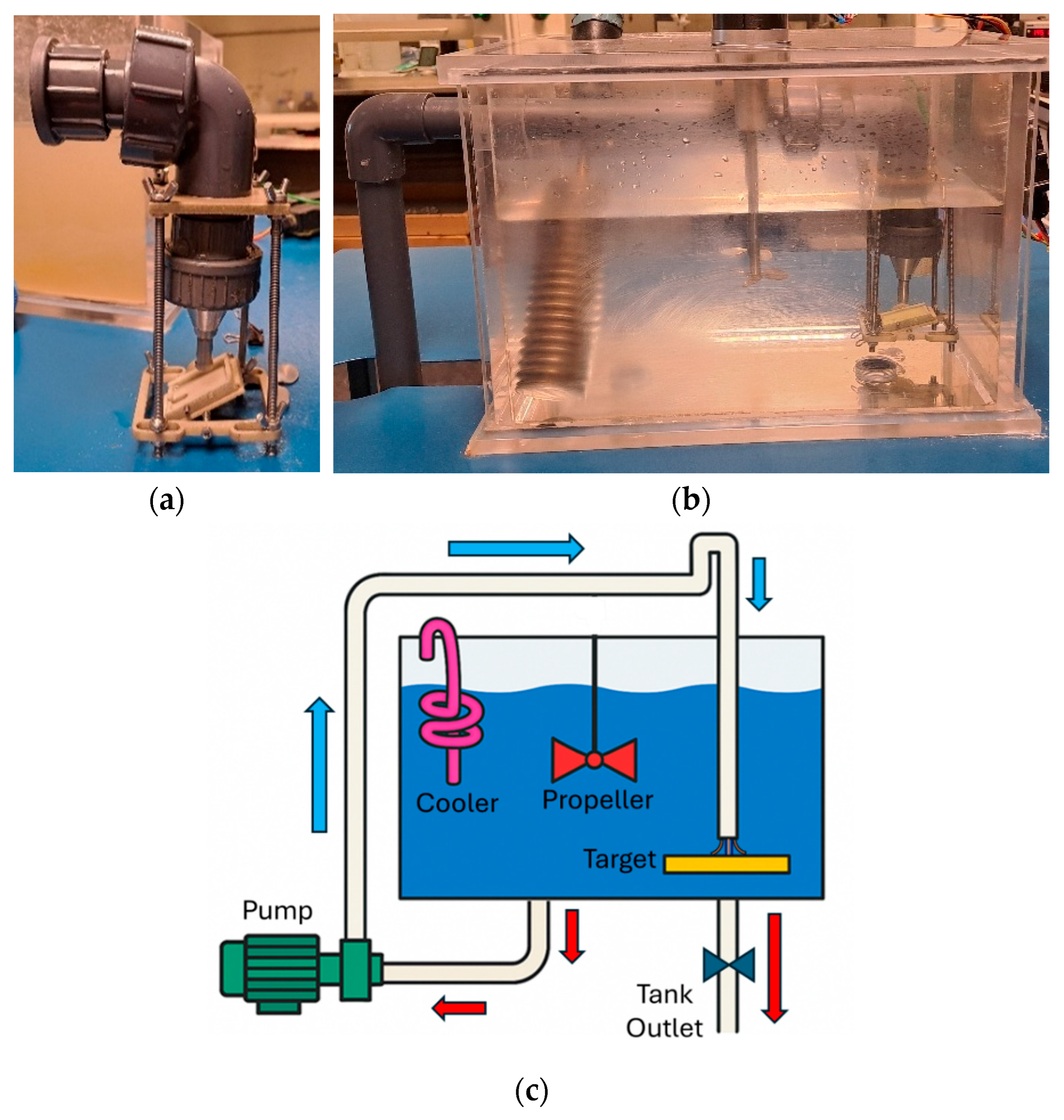
This study aims to address these gaps by experimentally calibrating the Oka erosion model for FR4 composite material under slurry impingement conditions that mimic sediment-laden tidal flows. A standard 90-degree impingement test was used, and erosion was measured in terms of total mass loss and radial topographic profiles, enabling localised erosion rate estimation. Simultaneously, CFD–DPM simulations were employed to extract impact velocity and angle distributions across the sample surface under identical conditions. These two datasets were then fused to calibrate the Oka model coefficients specific to FR4.
To the best of the authors’ knowledge, this is the first attempt to calibrate an empirical erosion model like Oka’s for a composite material using both experimental and CFD-derived data. To date, the Oka erosion model has been calibrated almost exclusively for metallic materials, primarily in oil and gas applications [
25]. Each of these calibrations is case-specific, with coefficients tuned to particular metals such as carbon steel, stainless steel, or Inconel [
4]. No prior studies have extended the model to fibre-reinforced composites, which differ fundamentally in their erosion response due to heterogeneous microstructures and anisotropic properties [
18]. The resulting erosion function is tailored to the material’s microstructural response and operating environment, thus providing a foundation for predictive erosion analysis in tidal turbine blades made from composite laminates. To date, the Oka erosion model has not been calibrated for fibre-reinforced composites such as GFRP, despite its widespread use in erosion prediction for metallic components in the oil and gas sector. This study addresses that gap by providing the first calibration of the Oka model for FR4 composites under slurry erosion conditions. The broader goal is to support erosion modelling and life prediction frameworks for tidal turbine blades, where progressive surface damage can compromise both structural integrity and hydrodynamic performance. This paper represents a key step in a broader research programme focused on erosion-induced degradation in composite-based renewable energy components.
3. Results and Discussion
This section presents the outcomes of the slurry erosion experiments and complementary CFD simulations, focusing on the erosion behaviour of the FR4 composite under 90° impingement at a slurry velocity of 12.5 m/s. The results are organised to reflect the experimental observations, including mass loss and surface topography, and their physical interpretation concerning composite erosion mechanisms. Together, these insights serve as a basis for calibrating the Oka erosion model in
Section 3.3.
3.1. Experimental Observations
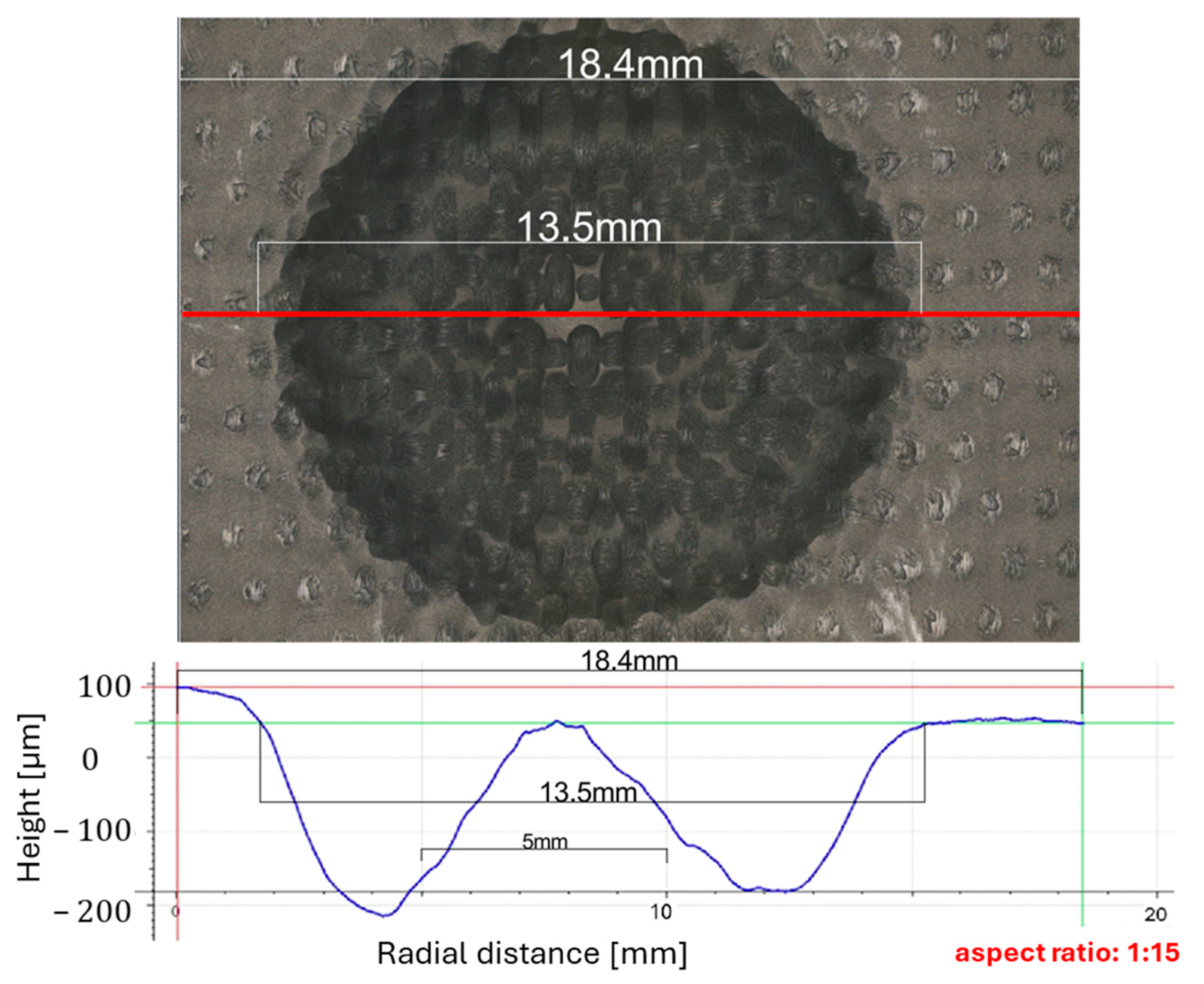
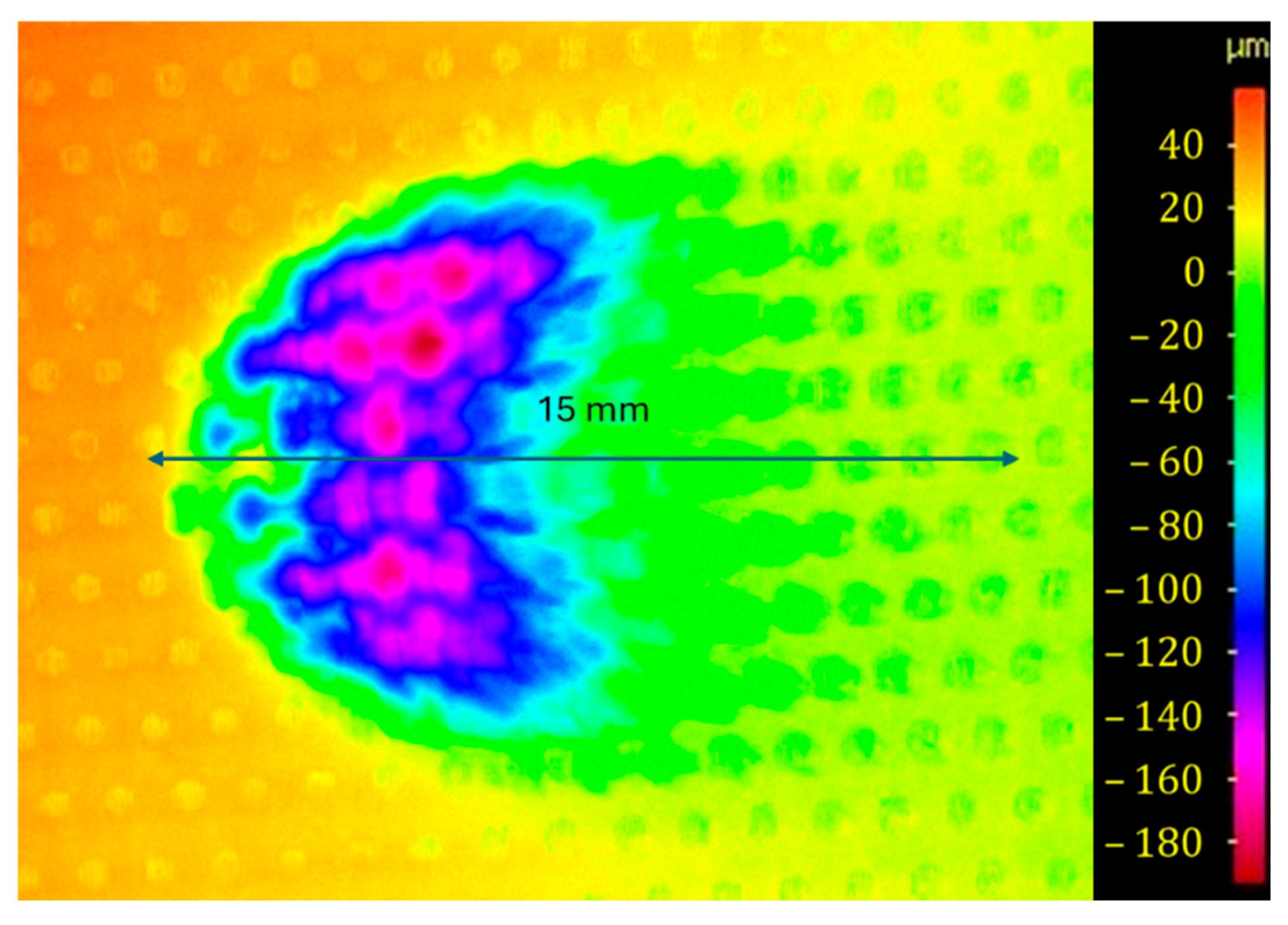
The experimental campaign provided both global and local insights into the erosion behaviour of FR4 composite under slurry impingement. Mass loss measurements quantified the overall material degradation, while high-resolution surface scans and microscopy revealed the spatial and morphological features of erosion. Together, these observations offer a comprehensive understanding of how the composite responds to high-velocity particle-laden flow, informing subsequent calibration of the empirical erosion model. In addition to bulk erosion rates, detailed inspection of the specimen surfaces revealed the spatial evolution of roughness features. The erosion morphology at 90° impingement consistently displayed a central stagnation zone flanked by two troughs of intensified material removal, forming a distinct W-shaped topographic profile. These troughs occurred approximately 3–6 mm from the centreline, aligning with the expected region of peak wall shear from radially decaying jet momentum. Profilometry confirmed the presence of surface disruption modes, including matrix fragmentation and fibre exposure, with damage severity increasing radially outward before tapering off. These observations indicate an angularly sensitive erosion regime, where both normal and oblique particle impacts jointly influence wear progression.
3.1.1. Mass Loss
Gravimetric analysis showed consistent and repeatable erosion across all tested durations. The measured erosion rates were 0.0192 g/h (30 min), 0.0272 g/h (60 min), and 0.0249 g/h (90 min), each representing the mean of three replicate specimens. These values indicate a stable erosion regime with no signs of saturation or nonlinear progression, supporting the assumption of steady-state wear under the applied slurry conditions. The 90 min erosion rate was selected for empirical model calibration, as this duration was deemed most representative of mature erosion behaviour, beyond the transient effects of surface conditioning and initial matrix wear. The erosion rate,
, was calculated using the following relation:
where Δm is the measured mass loss (g) and t is the erosion duration (h). The near-linear mass loss progression with time suggests that erosion kinetics in the tested FR4 composite are dominated by fibre–matrix detachment processes that stabilise after the early surface degradation phase. This further justifies using the 90 min data point as a robust basis for model fitting.
While the gravimetric erosion rates provide an overall measure of material loss, a more detailed view of erosion intensity as a function of radial position is presented in
Section 3.3. The spatial erosion profile confirms that mass loss is not uniformly distributed across the surface but peaks between 3 mm and 6 mm from the nozzle centre. This concentration of localised erosion supports the selection of the 90 min dataset as the most representative case for calibration, as it captures fully developed and spatially stabilised erosion patterns.
3.1.2. Surface Roughness and Topography
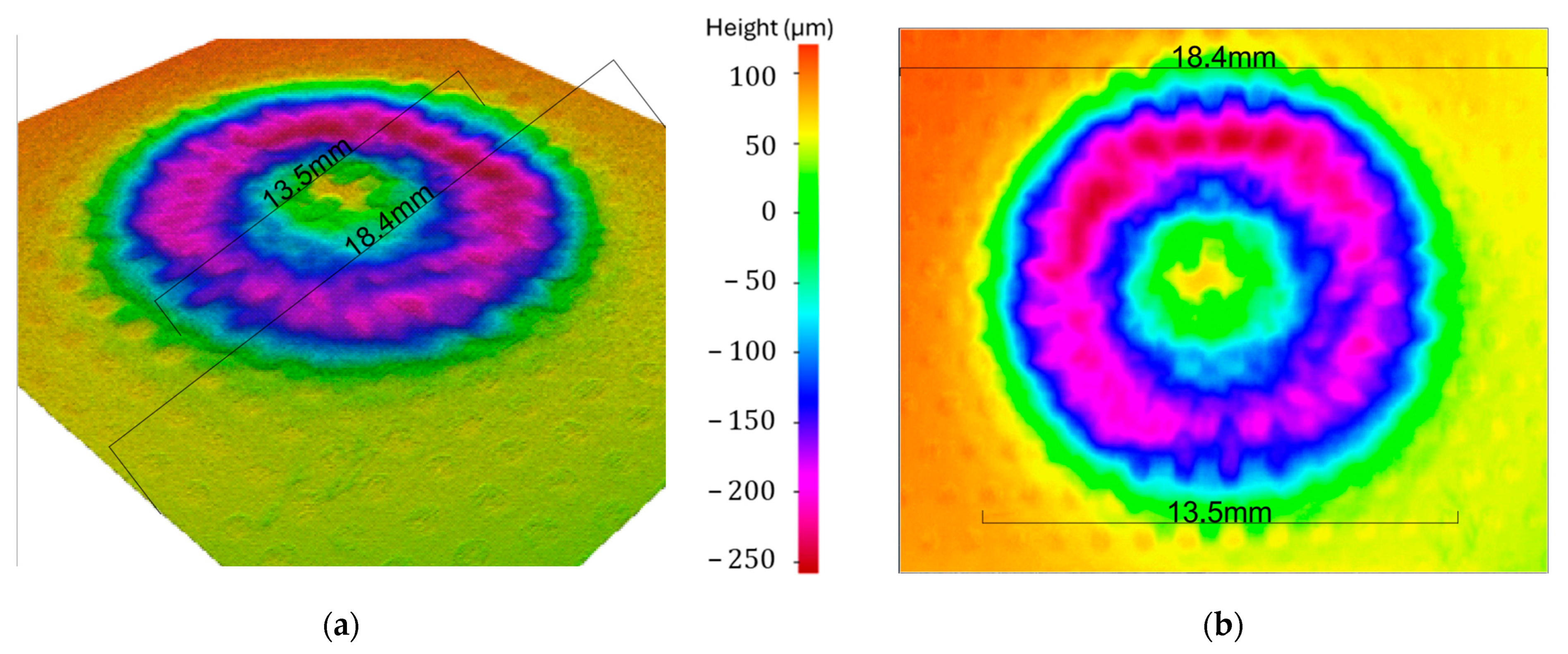
To spatially resolve the erosion morphology, surface profilometry was performed along the horizontal centreline of each specimen (
Figure 5). The resulting topographic scans revealed a characteristic W-shaped profile at 90° impingement, with minimal material loss at the stagnation point (
) and pronounced troughs occurring approximately
mm from the centreline (
Figure 6).
Figure 5 and
Figure 6 illustrate the same eroded region as captured by a high-resolution 3D laser scanner. These figures are not intended to display fibre or matrix details, but to highlight changes in surface elevation caused by particle erosion. The surrounding unscanned region shows the intact FR4 surface for comparison.
Figure 5 presents a 3D coloured height map of the same area, while
Figure 6 offers a top-down 2D view. This profilometric approach was selected to support future CFD simulations by providing spatially resolved surface roughness data, which complements the traditional mass loss metrics used to assess structural degradation. These off-centre peaks correspond to zones of visible fibre exposure and matrix fragmentation, indicating intensified material removal through combined cutting and micro-cracking mechanisms.
This morphology reflects the hydrodynamics of submerged jet erosion, where vortex formation and turbulent dispersion shift the zones of maximum wall shear stress and particle impact energy radially outward. The roughness distribution also suggests a transition in dominant damage mechanisms across the surface; near the centre, vertical impacts lead to matrix compression and limited removal, while in off-axis regions, high-energy oblique impacts promote fibre detachment, interfacial cracking, and matrix shearing.
These spatially heterogeneous roughness patterns highlight the need for erosion models that can accommodate localised surface damage rather than rely on global averages. This is particularly important for fibre-reinforced composites, where damage modes are highly sensitive to local impact orientation and energy. The extracted surface profiles serve as a critical reference for linking material response with localised flow and particle behaviour, forming the experimental foundation for the integrated modelling described in
Section 3.2 and
Section 3.3.
3.2. CFD Results
The CFD simulations provided high-resolution insight into the fluid dynamics and particle–surface interactions underpinning the observed erosion patterns. A 90° submerged jet impingement scenario was modelled in STAR-CCM+ using the Lagrangian Discrete Phase Model (DPM), with particle injection parameters matched to the experimental test conditions. This enabled the direct extraction of spatially resolved impact metrics, including velocity, angle, frequency, and residence time, over the target surface.
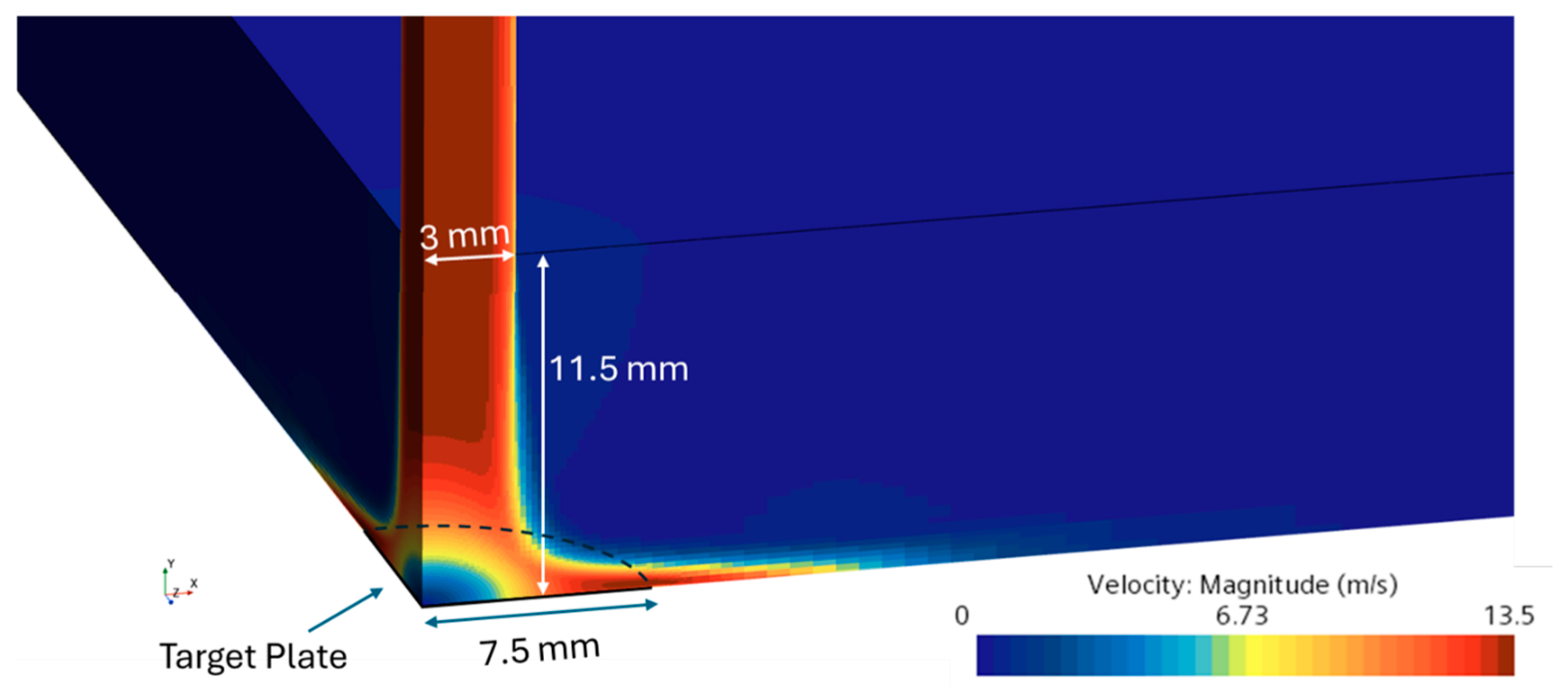
The velocity field exhibited a high-speed jet core along the central axis, terminating at a stagnation point located at
(
Figure 7). Upon impact, flow deceleration and a radial pressure gradient induced lateral dispersion across the plate, generating a radially spreading wall jet with declining core momentum. This behaviour is clearly seen in both planar (
Figure 7) and wall-adjacent (
Figure 8) velocity contours, while pressure distribution on the surface (
Figure 9) highlights the central peak associated with jet impingement.
Particle impact analysis revealed a non-uniform distribution of incident velocities and angles. Near the stagnation point, particles decelerated significantly and impacted the surface at nearly normal angles, resulting in minimal erosion due to low kinetic energy transfer. In contrast, particles striking the surface at radial distances between 3 and 6 mm retained higher velocities and encountered the surface at more oblique angles (
Figure 10). This zone coincided with the region of maximum experimentally measured erosion and is characterised by a synergistic interaction between normal impact damage and tangential shearing, which enhances matrix fragmentation and fibre exposure in FR4.
The angular and energetic conditions in this annular zone (50°–65°, 10–12 m/s) are particularly conducive to composite wear, which often arises from a combination of micro-cutting, fibre–matrix debonding, and progressive delamination, rather than purely brittle fracture as in metals. Beyond this region, both the velocity magnitude and impact frequency decreased due to particle dispersion and drag, thereby reducing the erosive potential.
Additionally, particle residence time analysis identified a ring between 5 mm and 7.5 mm from the centre with the longest contact durations (
Figure 10). These extended surface interactions may contribute to secondary wear modes such as surface fatigue or localised matrix degradation, even though they lie outside the primary erosion zone. The variation in residence time further emphasises the need for spatially resolved input in erosion modelling, especially for polymer matrix composites, where contact duration influences subsurface damage evolution.
Overall, the CFD data provided a comprehensive map of impact conditions, enabling informed segmentation of the experimental erosion surface for model calibration. The correlation between particle dynamics and erosion morphology is explored in detail in
Section 3.3.
3.3. Combined CFD and Experimental Outputs
To quantify spatial material loss, the eroded surface of the FR4 specimen was segmented into concentric radial rings at 0.1 mm intervals. The average surface height within each ring was used to estimate local volume loss. This analysis revealed that the erosion volume peaked prominently between 3 mm and 7 mm, with minimal loss occurring near the central stagnation zone and at the outer edges. These findings underscore the importance of spatially resolved erosion metrics for accurate model calibration, particularly for fibre-reinforced composites, where failure mechanisms such as matrix cracking, fibre pull-out, and interfacial delamination exhibit strong radial sensitivity.
CFD-based particle tracking revealed distinct radial variations in impact velocity and angle. Although the inlet jet velocity was 12.5 m/s directed vertically downward, the actual particle trajectories diverged due to jet expansion, flow turning, and inertial effects. At the specimen centre (r = 0 mm), particles impacted nearly perpendicularly to the surface, with angles approaching 90°, but with reduced velocities, attributed to stagnation and energy dissipation.
Radially outward, a distinct annular region formed where impact velocities rose sharply while impact angles declined. Between 3 mm and 6 mm, impact velocities reached 10–12 m/s, and impact angles fell to 50–60°, creating the ideal conditions for erosive wear. This region aligned precisely with the experimentally measured peak in erosion rate. Beyond 6 mm, both velocity and angle declined due to drag and flow dispersion, corresponding with the observed tapering in material loss.
Figure 11 illustrates these trends, with the top subplot showing LOWESS-smoothed profiles of impact velocity and angle based on CFD tracking. The bottom subplot overlays the experimental erosion rate (derived from mass loss measurements), revealing a strong correlation with the zone of high-velocity, oblique impacts. Shaded bands represent ±1 standard deviation around the means, reinforcing the robustness of the identified peak zone.
Notably, the radial variation in erosion severity is directly influenced by the spatial distribution of particle velocity, particularly the radial component, which governs the momentum transfer upon impact and intensifies surface damage in the 3–6 mm region. This 3–6 mm annular band represents the convergence of multiple erosive factors: increased kinetic energy, oblique incidence, and high impact frequency. These conditions result in maximum material removal and are consistent with the W-shaped erosion morphology observed experimentally. The agreement between CFD-derived impact dynamics and erosion test data validates the use of particle tracking as a predictive tool for erosion modelling.
In addition, particle impact frequency—determined by binning and normalising the number of hits per 0.1 mm band—confirmed a bell-shaped distribution, with the highest density of impacts occurring between r = 4.5 mm and 5.5 mm. This further supports the critical role of this radial zone in driving material loss.
Overall, the integration of CFD and experimental data confirms that a combination of dynamic flow parameters and local impact mechanics governs erosion in FR4 composites. The results justify the application of spatially resolved erosion modelling for composite calibration, as further detailed in
Section 3.4.
3.4. Calibration of the Oka Model for FR4
The main aim of this study was to calibrate the Oka erosion model for FR4, a composite material increasingly used in marine energy systems. Using erosion data from slurry impingement experiments and CFD-derived particle impact statistics, a tailored set of model coefficients was derived to enable predictive erosion assessment under representative tidal conditions. Calibration was performed through constrained nonlinear optimisation, with bounds imposed on the fitting parameters and a minimum R
2 threshold enforced to ensure predictive fidelity. The W-shaped erosion profile observed in our FR4 specimens contrasts sharply with the V-shaped scars typically predicted by Oka calibrations for metallic targets [
41]. This difference reflects the influence of composite-specific damage modes, such as fibre–matrix debonding, and reinforces the need for material-specific model calibration. This composite-specific formulation extends the applicability of the Oka model beyond metallic substrates, providing a practical tool for erosion evaluation in the design and analysis of tidal turbine blades.
The erosion rates derived from the experimental and CFD datasets were used to calibrate the Oka erosion model for the FR4 composite material, following the nonlinear optimisation procedure detailed in
Section 2.4. The objective was to minimise the mean squared error (MSE) between predicted and observed erosion rates while ensuring sufficient model accuracy through an R
2 constraint.
The calibrated parameter set, obtained using the SLSQP algorithm, yielded strong agreement between model predictions and experimental data, with
and
, despite the complex, angle-sensitive nature of composite erosion. The final optimised parameters give the calibrated Oka erosion equation for FR4 composites against sand slurry flow:
where
is 8.9058 × 10
−6 g/h, the measured Vickers hardness is 0.3786 GPa, and
and
are 12.5 m/s and
m, respectively.
These values suggest that erosion in FR4 is highly sensitive to velocity (via ) and particle diameter (via ) and features a sharply peaked angle dependence governed by . Notably, the extremely low value of reflects the fact that erosion is strongly localised around a narrow angular range, consistent with the off-axis erosion bands observed in the experimental topography.
Figure 12 presents the correlation between the measured and predicted erosion rates across all data points. The strong alignment along the ideal fit line confirms the predictive capability of the calibrated model. Minor deviations from the line are expected due to the heterogeneous microstructure of FR4, which introduces localised variability in response even under nominally identical impact conditions. Although the regression yielded an R
2 value of 0.844—slightly below the initially imposed threshold of 0.9—this is considered acceptable given the complex erosion mechanisms in composites, such as fibre bridging, resin cracking, and interfacial delamination. These mechanisms introduce nonlinearities and measurement noise that traditional erosion models do not fully capture. Importantly, the calibrated parameters remain physically interpretable, reinforcing confidence in their applicability to erosion prediction in marine environments.
This calibrated model now serves as the first empirical erosion function tailored to FR4 composite under slurry conditions, offering a basis for predictive erosion assessments in composite-based tidal turbine blades.
Overall, the calibrated Oka model offers a quantitatively reliable framework for predicting erosion in FR4 composites under slurry impingement, capturing the radial dependency of particle impacts with composite-specific response behaviour. While the model structure originates from studies of ductile metals, this adaptation for a fibre-reinforced polymer demonstrates promising alignment between simulation and physical erosion trends. Importantly, the model parameters obtained reflect the microstructural vulnerabilities of GFRP, including fibre–matrix debonding and resin cracking, which are critical for real-world deployments. These findings establish a foundational erosion prediction tool tailored for composite materials, directly impacting performance assessments in sediment-rich marine environments.
Although an threshold was initially set as a constraint during the calibration process, the final optimised parameters yielded an of 0.844 along with a very low mean squared error (). Given the heterogeneous nature of FR4 and its composite-specific damage mechanisms, perfect correlation is not always achievable. Attempts to further increase led to unphysical parameter values or overfitting. Importantly, the Oka model is inherently nonlinear with respect to its input variables and coefficients, and the fitting process, based on SLSQP nonlinear optimisation, already captures these relationships. The final model offers a physically interpretable and statistically robust representation of the erosion behaviour of FR4.
The W-shaped erosion profile observed across the target surface can be explained by the radial distribution of particle impact conditions derived from CFD. As shown in
Figure 11, near the nozzle centreline, particles exhibit low velocity and strike nearly normal to the surface, resulting in minimal erosion. As radial distance increases, impact velocity rises and impact angles become increasingly oblique, reaching a peak erosion zone around 3–6 mm from the centre. In this region, the radial velocity component of particle motion is especially significant and coincides with shallow impact angles—conditions that strongly exacerbate erosion in FR4. This reflects a semi-ductile erosion mechanism, where velocity plays a more dominant role than angle. Beyond this region, erosion decreases again due to further reduction in effective impact angle, despite continued high particle velocity.
The final calibrated Oka model yielded an
value of 0.844, slightly below the target threshold of 0.9. This modest deviation may be attributed to the inherent heterogeneity of FR4, which includes variations in fibre orientation, matrix composition, and local porosity. Furthermore, the empirical Oka model was originally developed for isotropic metallic materials and does not account for composite-specific features such as fibre–matrix bonding strength, anisotropic failure modes, or internal energy dissipation mechanisms. These differences are also reflected in the model parameters: the exceptionally low value of
and high
suggests that FR4 erosion is relatively insensitive to impact angle but highly responsive to radial velocity changes. For comparison, typical metallic values are
,
, and
[
4,
25]. In contrast, the current study found
, indicating a sharper particle-size dependence—consistent with brittle surface fragmentation mechanisms.
Together, these findings demonstrate that metal-calibrated models cannot be directly transferred to composites without introducing significant errors in both magnitude and spatial prediction. Future studies may explore multiscale or stochastic extensions of the current approach to incorporate microstructural variability and further enhance the robustness of erosion prediction in composite systems. To assess generality beyond the calibration condition, the calibrated FR4 coefficients were applied without re-tuning to an independent oblique impingement case at 45°, with results reported in
Section 3.6.
3.5. CFD Validation Against Particle Tracking Results
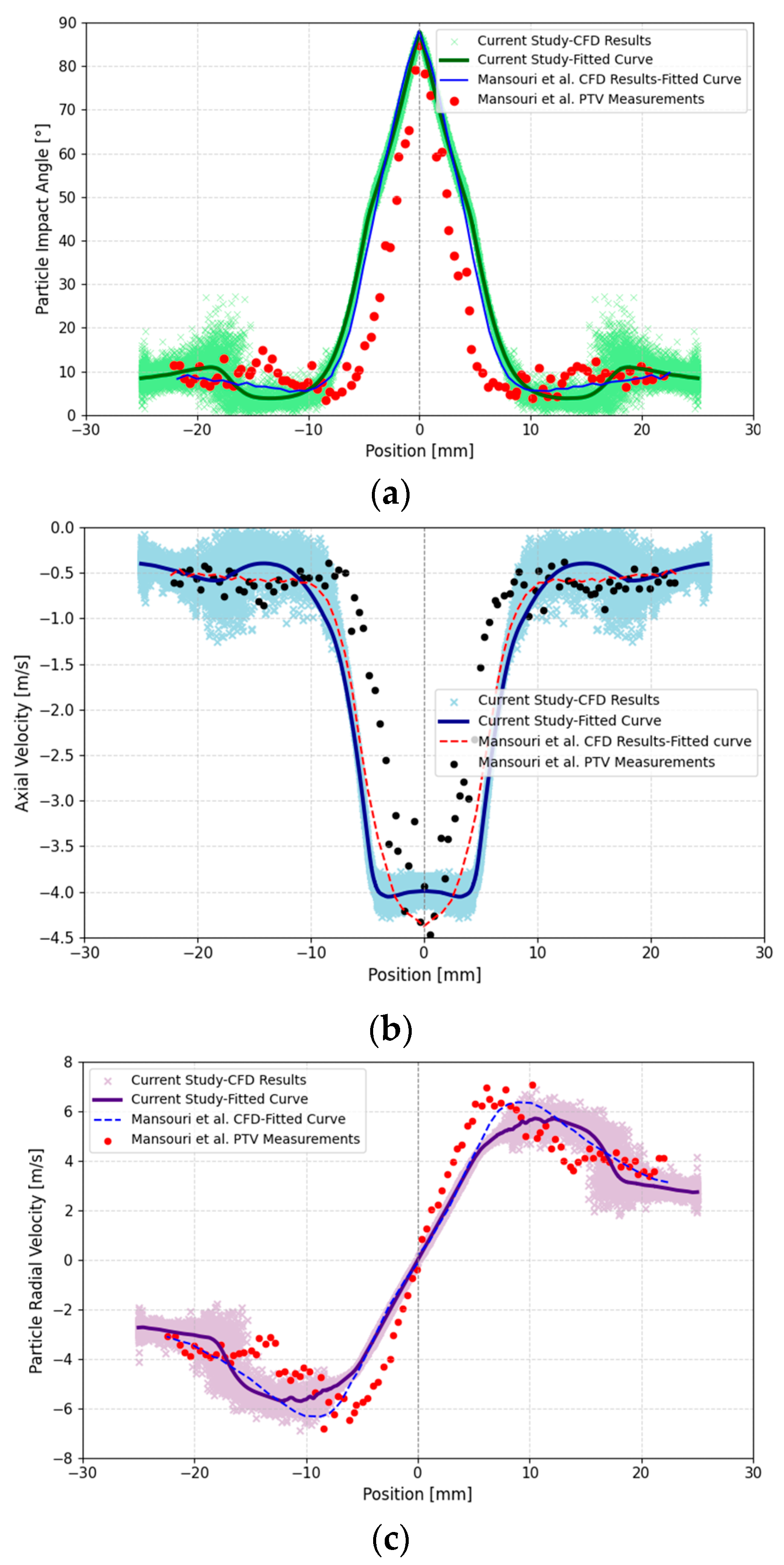
To verify the reliability of the CFD configuration used in this study, a dedicated validation was conducted against the slurry erosion particle tracking dataset reported by Mansouri et al. [
37]. Their work involved both CFD simulation and particle tracking velocimetry (PTV) to characterise the impact behaviour of 300 µm silica particles in a standard slurry jet impingement test. The reference test setup featured a nozzle–target distance of 12.7 mm and a nozzle inner diameter of 7.6 mm, with a mean jet velocity of 8.15 m/s. Although some dimensional details differ from the present study, the fundamental flow configuration and particle properties are sufficiently similar for comparative validation.
In this work, the CFD model was first used to simulate the same geometric and boundary conditions reported in, including the particle size and injection velocity. The resulting radial distributions of particle impact angle, axial velocity, and radial velocity were extracted and compared against both Mansouri et al.’s validated CFD results and their experimental PTV measurements. As shown in
Figure 13a–c, the agreement is strong across the entire impingement area (±22.5 mm radius), with our simulation closely replicating both the magnitude and trend of the reported profiles.
This validation confirms that the solver settings, meshing strategy, and Lagrangian particle tracking scheme adopted in the present CFD framework are capable of accurately capturing slurry particle–surface interaction dynamics. Accordingly, this validated configuration was then applied to the erosion test geometry used in our experiments to generate the impact conditions required for Oka model calibration.
3.6. Oka Erosion Model Validation Against Experiments (45° Case)
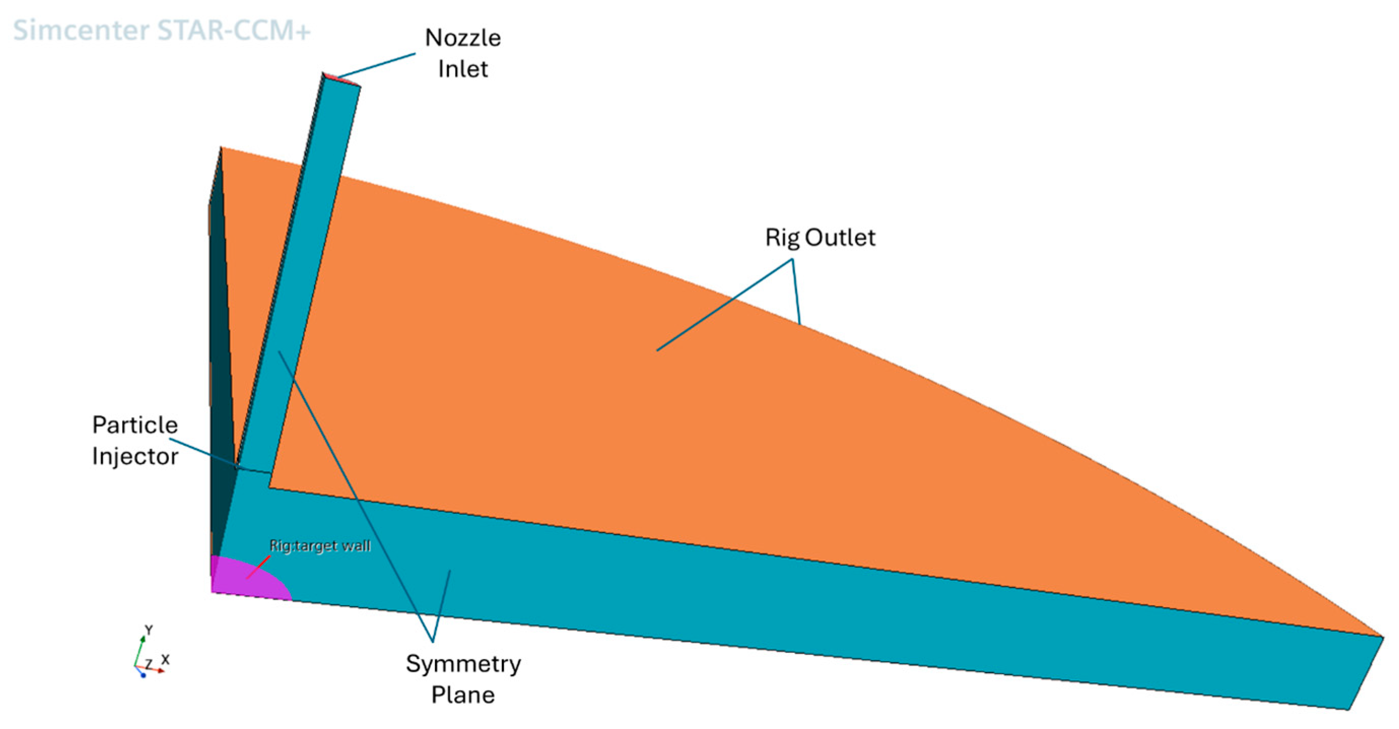
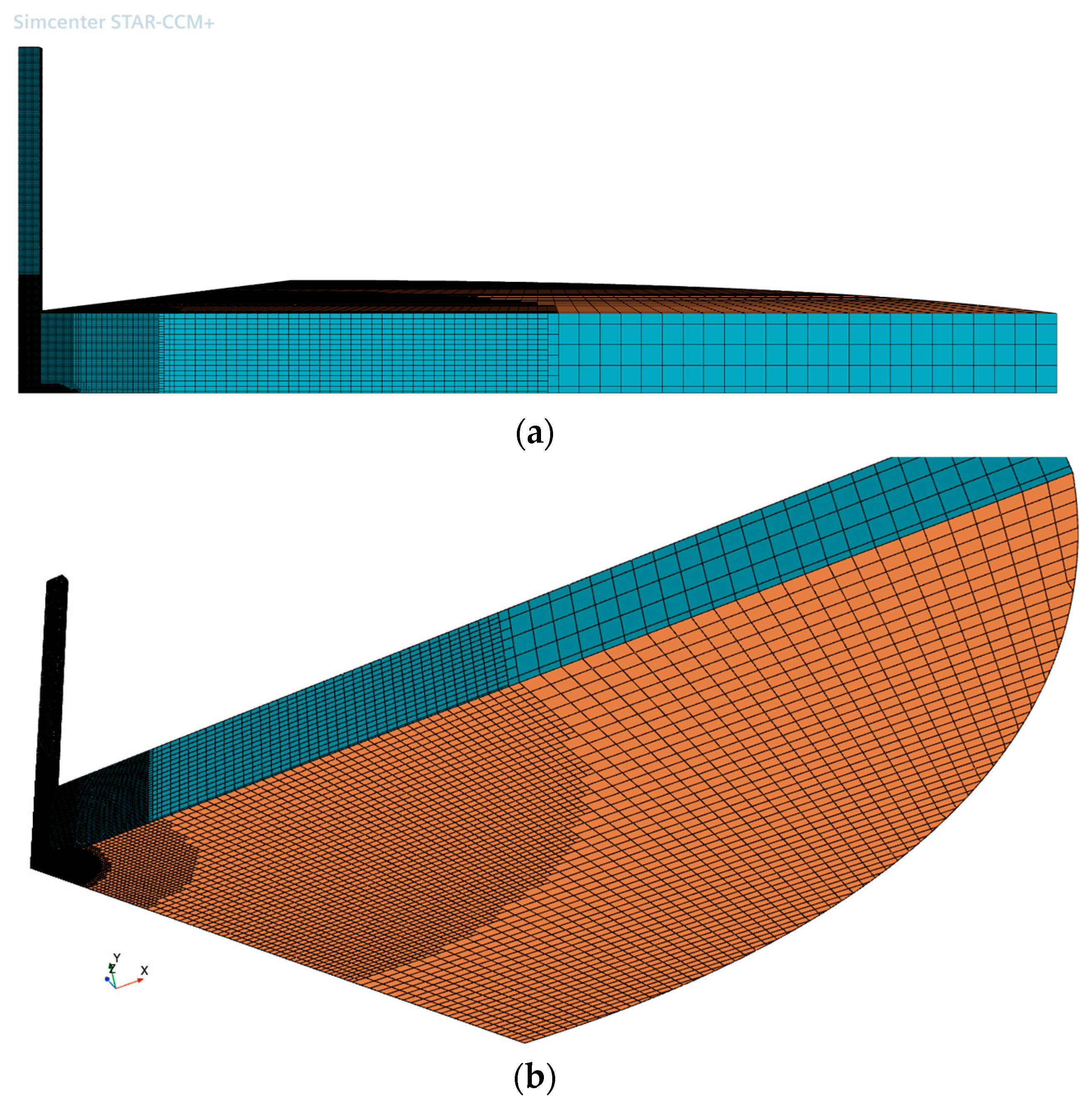
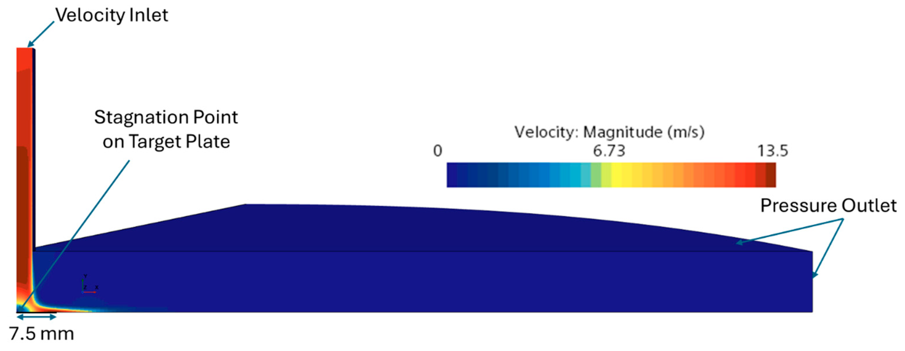
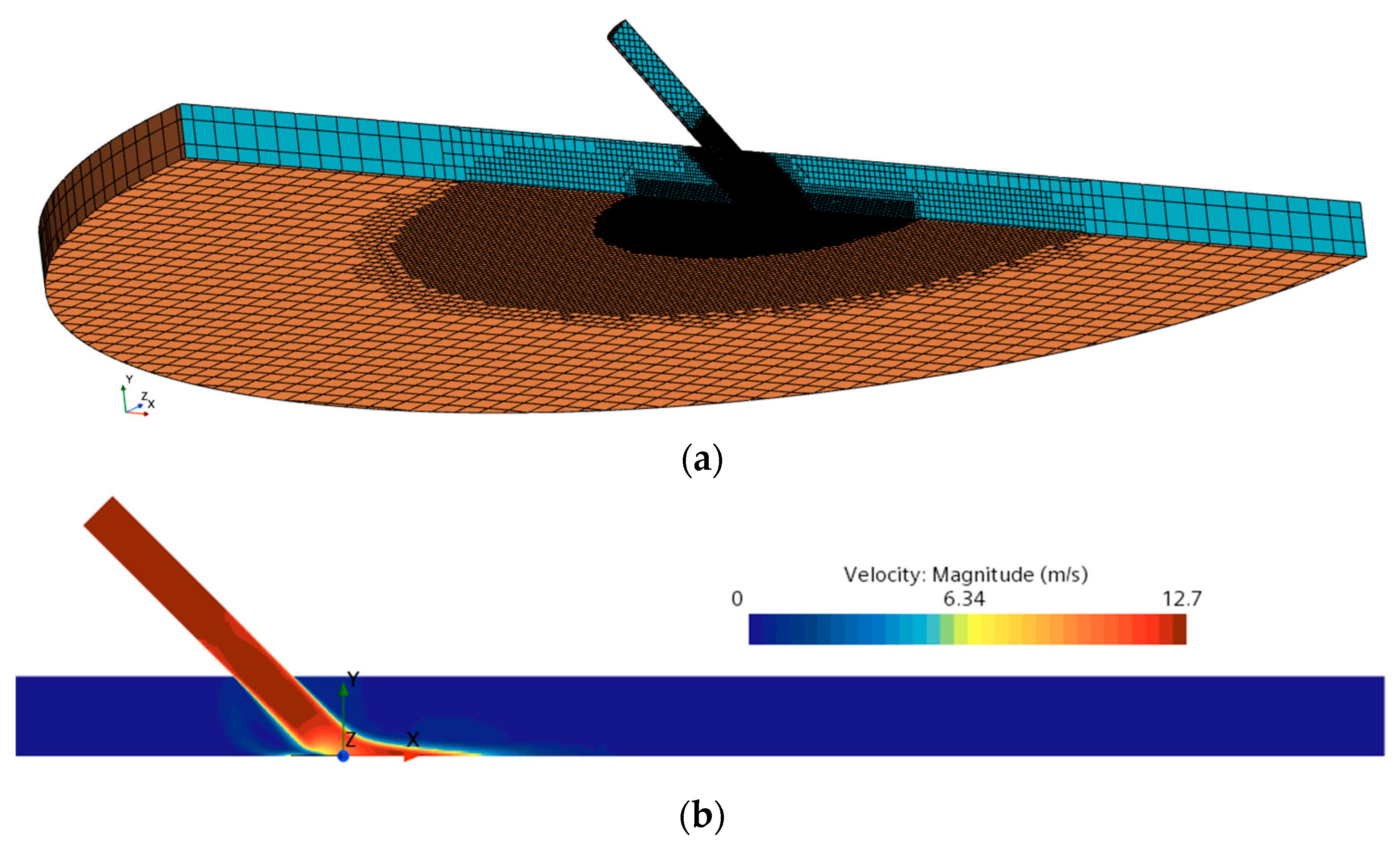
An additional CFD–erosion simulation was undertaken to replicate a laboratory slurry-impingement rig at a nominal 45° injection angle, using the same particle size (125 µm), injection velocity (12.5 m/s), volumetric flow rate, and standoff distance as the experiment, and applying the calibrated FR4 Oka coefficients without further tuning. To reduce computational cost while preserving the nominal symmetry of the configuration, the rig was modelled as a half-domain with a symmetry plane coincident with the jet mid-plane. The domain was discretised with an unstructured trimmer mesh incorporating near-wall prism layers and local refinement in the jet and impact regions, comprising 9.743 × 10⁶ cells.
The continuous phase was advanced to steady state within a RANS framework using the SST k–ω turbulence model with second-order convection and segregated pressure–velocity coupling accelerated by algebraic multigrid; particle trajectories were computed with a steady Lagrangian tracker for a monodisperse 125 µm phase, and wall erosion was evaluated using the calibrated Oka formulation. Boundary conditions comprised a velocity inlet at the nozzle, a pressure outlet downstream, no-slip walls on all solid surfaces (including the target plate), and a symmetry condition at the mid-plane; the particle volumetric flow at the inlet matched the experimental setting, and impacts were sampled on the target wall for post-processing.
Figure 14 summarises the computational setup and flow velocity magnitude in the symmetry mid-plane. The spatial distribution of the particle incident angle on the target and the Cartesian components of the impact velocity are reported in
Figure 15: (a) incident angle, (b)
, (c)
, and (d)
. The experimentally measured wear morphology under identical operating conditions is shown in
Figure 16.
Using these settings, the model predicted an area-integrated erosion rate of 0.0143 g/h, whereas the corresponding measured value for a 90 min 45° test on FR4 was 0.0124 g/h, yielding an absolute difference of 1.92 × 10
−3 g/h (15.5 per cent). This agreement, achieved without additional tuning, indicates that the calibrated Oka model generalises to oblique impacts and supports its predictive use for FR4 under operating conditions that differ from those used for calibration. The qualitative correspondence between the simulated incident angle/velocity fields (
Figure 15) and the measured wear footprint (
Figure 16) further supports the physical consistency of the coupled CFD–erosion framework.
4. Conclusions
This study presented a generalisable methodology for calibrating empirical erosion models for composite materials, based on the integration of controlled erosion experiments with CFD-derived particle impact characteristics. While the case study focused on FR4, a glass fibre-reinforced epoxy laminate, the framework is applicable to a broad range of composite systems in erosive flow environments. This approach is especially relevant to components such as tidal turbine blades and hydroturbines, where fibre-reinforced composites are increasingly adopted for their corrosion resistance and mechanical durability.
A slurry jet test at 12.5 m/s was conducted under a 90° normal injection to characterise radial erosion patterns, supported by high-resolution surface scans. Complementary CFD simulations provided detailed impact velocity and angle distributions using Eulerian–Lagrangian particle tracking. The Oka erosion model was calibrated using a constrained nonlinear optimisation scheme, achieving a strong correlation with experimental results () and accurately capturing the composite-specific erosion morphology and trends. Applying the calibrated coefficients to an independent 45° impingement case (without re-tuning) yielded 0.0143 g/h predicted versus 0.0124 g/h measured (15.5% error). This result demonstrates that the FR4-specific Oka calibration generalises beyond the 90° setup, supporting practical use for oblique impacts and complex component geometries.
Although a single axisymmetric test configuration was employed, the resulting radial variation in impact conditions covered a full spectrum of angles and velocities, allowing for robust parameter estimation. This variation reflects the diverse loading conditions typically experienced in operational systems and supports the model’s broader applicability.
The calibrated model can now be integrated into CFD platforms to predict erosion under complex flow conditions, including curved surfaces and multi-angle particle strikes, as encountered in tidal turbines. This capability enables the predictive assessment of erosion damage, offering practical value for optimising maintenance schedules and coating replacement strategies. While no quantified operational savings are presented in this study, the modelling framework establishes a foundation for future cost–benefit analyses linking surface degradation to performance loss and lifecycle costs.
