Article

Global Fixed-Time Target Enclosing Tracking Control for an Unmanned Surface Vehicle Under Unknown Velocity States and Actuator Saturation

by
Xinjie Han
1,*,
Guanglu Ma
1,
Yunsheng Fan
1,2,
Dongdong Mu
1,
Feng Sun
3,
Linlong Shi
4 and
Hongbiao Li
4
1
College of Marine Electrical Engineering, Dalian Maritime University, Dalian 116026, China
2
Key Laboratory of Technology and System for Intelligent Ships of Liaoning Province, Dalian 116026, China
3
COSCO Shipping Heavy Industry (Dalian) Co., Ltd., Dalian 116113, China
4
Shanghai KeLiang Information Technology Co., Ltd., Shanghai 200233, China
*
Author to whom correspondence should be addressed.
J. Mar. Sci. Eng. 2025, 13(11), 2094; https://doi.org/10.3390/jmse13112094
Submission received: 9 October 2025 / Revised: 24 October 2025 / Accepted: 29 October 2025 / Published: 3 November 2025
(This article belongs to the Special Issue New Technologies in Autonomous Ship Navigation)

Abstract

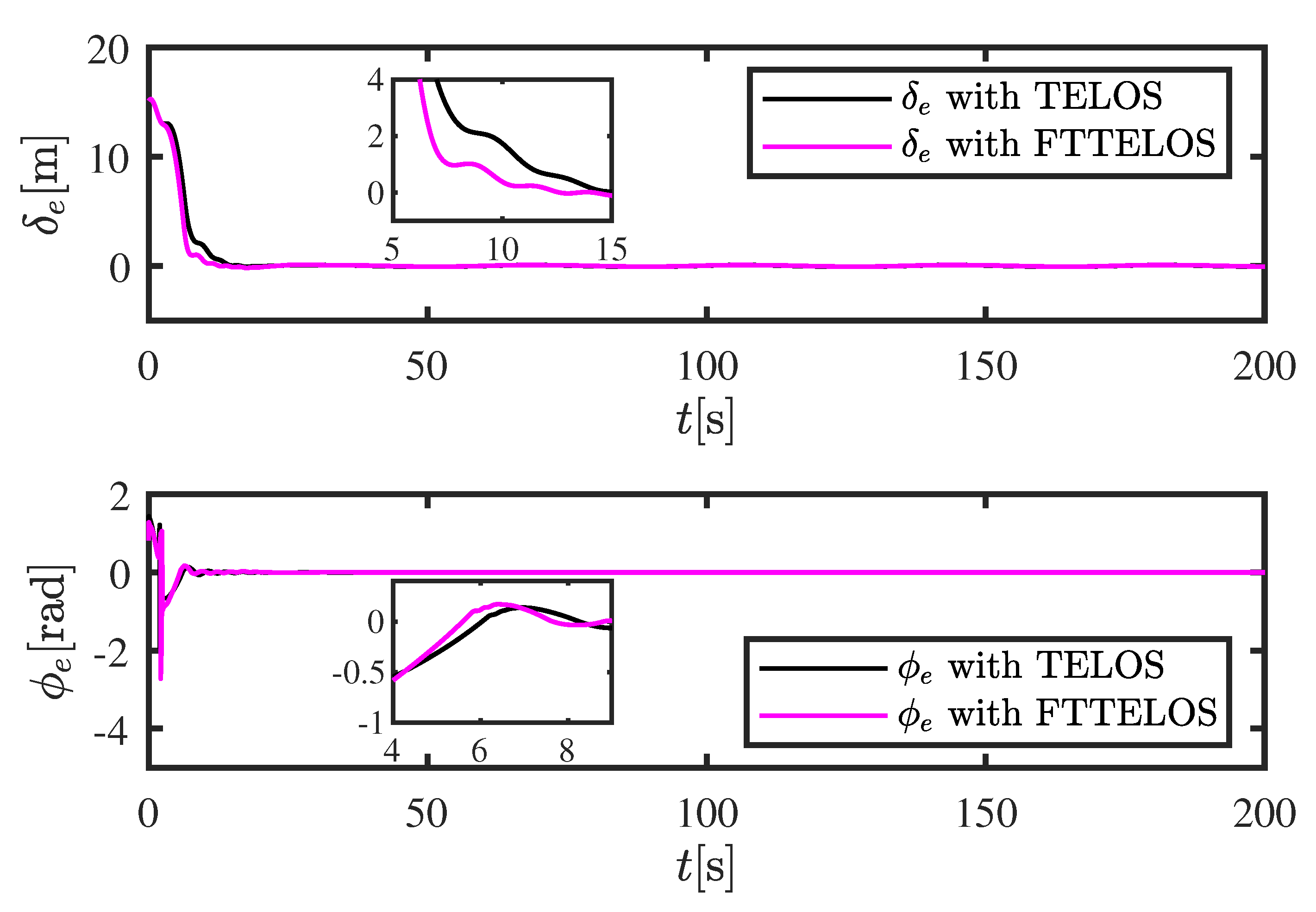
This paper presents a global fixed-time control framework to address the target circumnavigation tracking problem of underactuated unmanned surface vehicles (USV) under unknown velocity states, lumped uncertainties, and actuator saturation. At the core of this approach is a novel fixed-time target-enclosing line-of-sight (FTTELOS) guidance law, designed to generate the desired heading angle and surge velocity. To estimate unknown velocities, external disturbances, and unmeasured system states, a set of fixed-time observers is constructed, consisting of a velocity observer, a disturbance observer, and a high-dimensional extended state observer (HFTESO). Moreover, to enhance robustness and effectively tackle actuator saturation, the control scheme incorporates a fixed-time sliding mode controller, a dynamic auxiliary system, and a fixed-threshold event-triggered mechanism. Simulation results using SimuNPS demonstrate that the proposed method enables rapid and smooth target circumnavigation, with all system errors converging to an arbitrarily small neighborhood of the origin within a fixed time. Theoretical analysis and simulation studies confirm the effectiveness and robustness of both the FTTELOS guidance law and the integrated control strategy. Quantitatively, compared with the traditional target-enclosing line-of-sight (TELOS) method, the proposed FTTELOS reduces the convergence time of the distance error δ e from 13.64 s to 10.22 s and the angular error ϕ e from 10.46 s to 7.52 s, demonstrating a significant improvement in convergence speed and overall control performance.

1. Introduction

Unmanned surface vehicles (USV) have emerged as essential platforms for marine exploration and technological advancement, playing a pivotal role in maritime security, resource exploitation, environmental monitoring, and economic development. In the field of USV motion control, several key scenarios have been extensively explored, including path following [1,2,3,4,5], trajectory tracking [6,7,8], and target tracking [9,10]. Among these, target enclosing is a critical control task when a USV is required to maneuver around a target or a specific area in a circular pattern. This capability has practical applications in scenarios such as surveillance of non-cooperative objects, periodic scanning of fixed zones, and offshore infrastructure inspection.
Recently, increasing attention has been devoted to the development of target-enclosing control strategies for underactuated platforms such as unicycles and quadrotors. A cyclic pursuit algorithm that enables unicycles to achieve circular formations was presented in [11], while [12] introduced a two-stage hybrid control strategy specifically designed for enclosing tasks. In [13], a bearing-only sensing approach was proposed to enclose static or disk-shaped targets, and [14] employed a distance-based enclosing law to track slow-moving targets without requiring accurate velocity information. A vision-based guidance strategy was adopted in [15] for aerial vehicles to encircle maneuvering targets with unknown constant velocities, whereas [16] proposed a velocity-adaptive enclosing controller for quadrotors based on online velocity estimation. Additionally, ref. [17] developed a novel method for enclosing a moving target using unicycles without relying on direct distance measurements.
Due to their simplicity and ease of implementation, line-of-sight (LOS) guidance methods have been widely employed in USV motion control. These strategies emulate the behavior of a human helmsman by computing the desired heading angle based on geometric relationships, thereby facilitating smooth path following. In [18], an LOS controller utilizing the moving Frenet frame was developed to provide a unified framework for both fully actuated and underactuated USVs. To mitigate constant sideslip angles, an integral LOS approach was introduced in [19]. Furthermore, ref. [20] proposed an observer-enhanced LOS strategy capable of estimating and compensating for time-varying lateral drift. Addressing the problem of target enclosing under unknown sideslip effects, ref. [21] combined an LOS-based guidance law with a current estimator to improve tracking accuracy. However, the LOS-based target-enclosing approach in [21] focuses only on asymptotic convergence and does not consider fixed-time convergence performance. In contrast, this paper extends the LOS framework by introducing a fixed-time convergence mechanism, ensuring that both the enclosing distance and angular errors converge to a small neighborhood of the origin within a predefined time, thereby significantly improving convergence speed and tracking predictability.
To address modeling uncertainties and external disturbances, nonlinear disturbance observers (NDOs) have been widely adopted to estimate lumped perturbations, thereby enhancing system robustness and reducing tracking errors. In [22], a high-precision observer was developed to capture complex disturbances and improve trajectory tracking performance. A fixed-time extended state observer (FESO) was proposed in [23] to concurrently estimate unmeasured velocities and unknown disturbances, thus increasing system resilience. Under sensor fault conditions, ref. [24] introduced a deep learning-based tracking controller that integrates a dual deep neural network architecture with an improved LOS guidance law, achieving significant error reduction in simulation studies.In addition, this work extends previous fixed-time state observer designs by developing a high-dimensional fixed-time extended state observer (HFTESO) that is specifically tailored to the dynamics of the proposed USV system.
Considering the complexity of external environments, sliding mode control (SMC) has been extensively studied for USV motion control, owing to its strong robustness and fast dynamic response.In recent studies, the integration of learning-based models into marine control systems has also been explored to handle stochastic ocean disturbances and improve autonomy [25]. Various SMC-based algorithms have been developed in this field, including integral SMC [26], proportional–integral SMC [27], and terminal SMC (TSMC) [28]. In [29], a trajectory-following controller utilizing dual integral sliding surfaces was implemented and validated through full-scale experiments. However, due to theoretical constraints, the method proposed by Ashrafiuon et al. [29] was limited to tracking only specific classes of curves. To address this limitation, Yu et al. [30] refined the guidance strategy and developed an enhanced SMC-based controller, with its stability rigorously proven through Lyapunov analysis. Furthermore, ref. [31] introduced an adaptive SMC approach for nonlinear dynamic systems, which, unlike conventional TSMC designs, avoids singularity problems and does not require prior knowledge of bounds on lumped disturbances.
Event-triggered control (ETC) has garnered increasing attention in recent years due to its ability to reduce communication and computational burdens [32]. In contrast to conventional time-triggered schemes, ETC updates feedback signals only when specific triggering conditions are satisfied, thereby significantly lowering network bandwidth usage and reducing actuator wear. This paradigm has been effectively applied to linear systems [33], nonlinear systems [34], and multi-agent systems [35], and is now widely utilized in applications such as trajectory tracking [36], path following [37], and formation control [38]. By minimizing unnecessary signal transmissions, ETC offers notable advantages in resource-constrained environments, including reduced update frequency and extended actuator lifespan.
Despite the significant progress in target-enclosing and LOS-based guidance control for unmanned surface vehicles, most existing studies ensure only asymptotic or finite-time convergence, without providing a guaranteed global fixed-time convergence framework. Furthermore, few works simultaneously consider velocity unavailability, actuator saturation, and disturbance compensation within a unified design. In contrast, this paper develops an integrated fixed-time target-enclosing control scheme that systematically addresses these challenges and ensures rapid, robust convergence under complex marine environments.
Based on the above analysis, this paper develops a global fixed-time control strategy for target circumnavigation tracking of a USV, featuring the following key innovations:
(1)
In the design of the target enclosing task in this study, practical ocean navigation conditions are fully taken into account. To address the unknown velocity of the follower vessel and the unmeasurable relative velocity states of the target vessel, a fixed-time velocity observer is developed. In addition, a high-dimensional fixed-time extended state observer (HFTESO) is proposed to estimate the unknown state variables of the system. With the aid of this set of observers, the unknown system information can be accurately estimated within a fixed-time interval.
(2)
A novel FTTELOS guidance law is proposed in this paper. It ensures that both the enclosing distance error and angular error converge to an arbitrarily small neighborhood of the origin within a fixed time. The FTTELOS framework integrates guidance laws for both heading angle and surge velocity, resulting in accelerated convergence. Additionally, an adaptive update law for the look-ahead distance, driven by the enclosing distance error, is introduced to further enhance the convergence rate of the system.
(3)
A fixed-time saturated sliding mode controller under a fixed-threshold event-triggered mechanism is proposed in this paper to address two key challenges in target enclosing tasks: frequent actuator chattering and actuator saturation. To further enhance control performance, a Gaussian-function-based sliding mode reaching law is designed, which effectively suppresses chattering and ensures smoother control output.
The structure of this paper is organized as follows: Section 2 introduces the relevant preliminaries and problem formulation used in this study. Section 3 presents the design of the proposed observers and guidance law, along with a detailed stability analysis. Section 4 focuses on the design and analysis of the proposed controller. Section 5 provides simulation results to validate the effectiveness of the approach. Section 6 discusses limitations and practical deployment challenges. Section 7 outlines real-world implementation considerations and expectations. Finally, Section 8 summarizes the contributions and concludes the paper.
It is important to note that this paper primarily aims to make a methodological contribution by establishing a comprehensive fixed-time control framework for target-enclosing tasks. Although real-world validation has not yet been conducted, the proposed approach is designed with practical implementation feasibility in mind and serves as a foundation for future experimental deployment.

2. Preliminary and Problem Formation

2.1. Preliminary

Notation. The norm s i g α ( μ i ) is defined as s i g α ( μ i ) = μ i α sgn ( μ i ) , i = 1 , 2 , , n . sgn ( · ) denotes the signum.
The following system is considered:
x ˙ ( t ) = f ( x ( t ) ) , x ( 0 ) = 0 , f ( 0 ) = 0
where x ( t ) R n represent the state variables of the system. f ( · ) is a smooth nonlinear function.
Definition 1 
([39]). If (1) is Lyapunov stable, and there exists a finite time T s ( x 0 ) , x ( t ) = 0 holds on when t > T s . Furthermore, T s is independent of the system states. Then the system (1) is fixed-time stable.
Lemma 1. 
For system (1), if there exists δ 1 , δ 2 , α ( 0 , 1 ) , β ( 1 , + ) , and consider the Lyapunov candidate function (LCF) V ( x ( t ) ) satisfying
V ˙ ( x ( t ) ) δ 1 V α ( x ( t ) ) δ 2 V β ( x ( t ) )
Then the system is globally fixed-time stable and the setting time is expressed as
T T max : = 1 δ 1 ( 1 α ) + 1 δ 2 ( β 1 )
Lemma 2 
([40]). If there exists δ 1 , δ 2 , α , θ ( 0 , 1 ) , β ( 1 , + ) , ϑ ( 0 , + ) , and consider LCF V ( x ( t ) ) satisfying
V ˙ ( x ( t ) ) δ 1 V α ( x ( t ) ) δ 2 V β ( x ( t ) ) + ϑ
Then the system is practically fixed-time stable and the setting-time is expressed as
T T max : = 1 δ 1 θ ( 1 α ) + 1 δ 2 θ ( β 1 )
and
lim t T x | V ( x ) min δ 1 1 α ϑ 1 θ 1 α , δ 2 1 β ϑ 1 θ 1 β
Lemma 3. 
For any σ > 0 and any vector x R n , the following inequality holds:
0 x 2 x T tanh x σ n k p σ
where k p is a constant satisfying k p = e ( k p + 1 ) , i.e., k p = 0.2785 .
Lemma 4 
([41]). For any ω 1 R , ω 2 R , and any positive real number γ, the following inequality holds:
ω 1 ω 2 γ m m | ω 1 | m + 1 n γ n | ω 2 | n
where m > 1 , n > 1 , and ( m 1 ) ( n 1 ) = 1 .

2.2. USV Model

Due to the inherent complexity of the full six-degree-of-freedom (6-DOF) model for unmanned surface vehicles (USVs), it poses significant challenges for theoretical analysis and controller design. As a result, most existing studies on USV motion control simplify the model by neglecting the heave, pitch, and roll dynamics, and concentrate only on the surge, sway, and yaw motions. This leads to a reduced-order model, where the original 6-DOF system is approximated by a more tractable 3-DOF representation.
The mathematical model of 3-DOF underactuated USV is usually composed of kinematic and dynamic equations. The specific expressions of them are as follows:
η ˙ = R ( ψ ) v M v + C ( v ) v + D ( v ) v = τ + D ω
where η = [ x , y , ψ ] T and v = [ u , v , r ] T , with x, y, and ψ representing the global position and heading angle of the USV in the inertial coordinate frame. The elements u, v, and r correspond to the surge velocity, sway velocity, and yaw rate, respectively. The vector D ω = [ D u , D v , D r ] T represents the aggregated uncertainties acting on the USV, including time-varying unknown environmental disturbances and unmodeled dynamics. The disturbances include modeling uncertainties and parameter variations encountered during USV navigation. The control input is given by τ = [ τ u , 0 , τ r ] T , where τ u is the longitudinal thrust generated by the USV’s tail propeller, and τ r denotes the yaw moment applied by the rudder. The matrix R ( ψ ) is the rotation transformation matrix, M is the inertia matrix with added mass terms, C ( v ) denotes the Coriolis and centripetal force matrix, and D ( v ) is the linear damping matrix. Their explicit forms [42] are given as:
R ( ψ ) = cos ψ sin ψ 0 sin ψ cos ψ 0 0 0 1 , M = m 11 0 0 0 m 22 0 0 0 m 33 , C ( v ) = 0 0 m 22 v 0 0 m 11 u m 22 v m 11 u 0 , D ( v ) = d 11 0 0 0 d 22 0 0 0 d 33 .
Here, m 11 and m 22 represent the combined rigid-body and added mass in surge and sway directions, while m 33 corresponds to the inertia and added inertia in yaw. The coefficients d 11 , d 22 , and d 33 represent the linear damping terms in the respective 3-DOF channels.
x ˙ = u cos ψ v sin ψ y ˙ = u sin ψ + v cos ψ ψ ˙ = r
u ˙ = f u ( u , v , r ) + τ u m 11 + D u m 11 v ˙ = f v ( u , v , r ) + D v m 22 r ˙ = f r ( u , v , r ) + τ r m 33 + D r m 33
where
f u ( u , v , r ) = m 22 m 11 v r d 11 m 11 u f v ( u , v , r ) = m 11 m 22 u r d 22 m 22 v f r ( u , v , r ) = m 11 m 22 m 33 u v d 33 m 33 r
Equations (9)–(12) describe the three-degree-of-freedom (3-DOF) kinematic and dynamic model of an underactuated unmanned surface vehicle (USV) operating on the horizontal plane. Specifically, Equation (9) expresses the general form of the USV motion, where η = [ x , y , ψ ] T denotes the position and heading angle in the Earth-fixed frame, and v = [ u , v , r ] T represents the surge, sway, and yaw velocities in the body-fixed frame. Equation (10) expands the kinematic relationship, indicating how the surge and sway velocities ( u , v ) determine the translational motions ( x ˙ , y ˙ ) through the rotation matrix R ( ψ ) , while ψ ˙ = r defines the yaw dynamics. Equation (11) represents the dynamic behavior of the USV, where M, C ( v ) , and D ( v ) are the inertia (including added mass), Coriolis–centripetal, and damping matrices, respectively, τ = [ τ u , 0 , τ r ] T is the control input consisting of surge force and yaw moment generated by the twin propellers, and D ω denotes the external disturbance vector caused by wind, waves, and currents. Finally, Equation (12) provides the nonlinear coupling terms f u , f v , and f r , representing hydrodynamic interactions among surge, sway, and yaw. This reduced 3-DOF model captures the dominant horizontal-plane dynamics of the USV and reasonably neglects heave, pitch, and roll, a common simplification in surface vessel control.
Assumption 1. 
The lumped uncertainties D w = [ D u , D v , D r ] T is time-varying and bounded. Moreover, its time derivative is also bounded, that is, D ˙ w D ¯ w .
Remark 1. 
It should be noted that if Assumption 1 is temporarily violated due to sudden waves or external shocks, the boundedness of D w and its derivative may not hold, causing short-term estimation or tracking deviations. Nevertheless, the proposed fixed-time observer and controller are robust, enabling the system to quickly recover once the disturbance returns to normal levels, demonstrating strong resilience in non-ideal conditions.
Figure 1 illustrates the proposed target-enclosing control scheme.

2.3. Problem Formulation

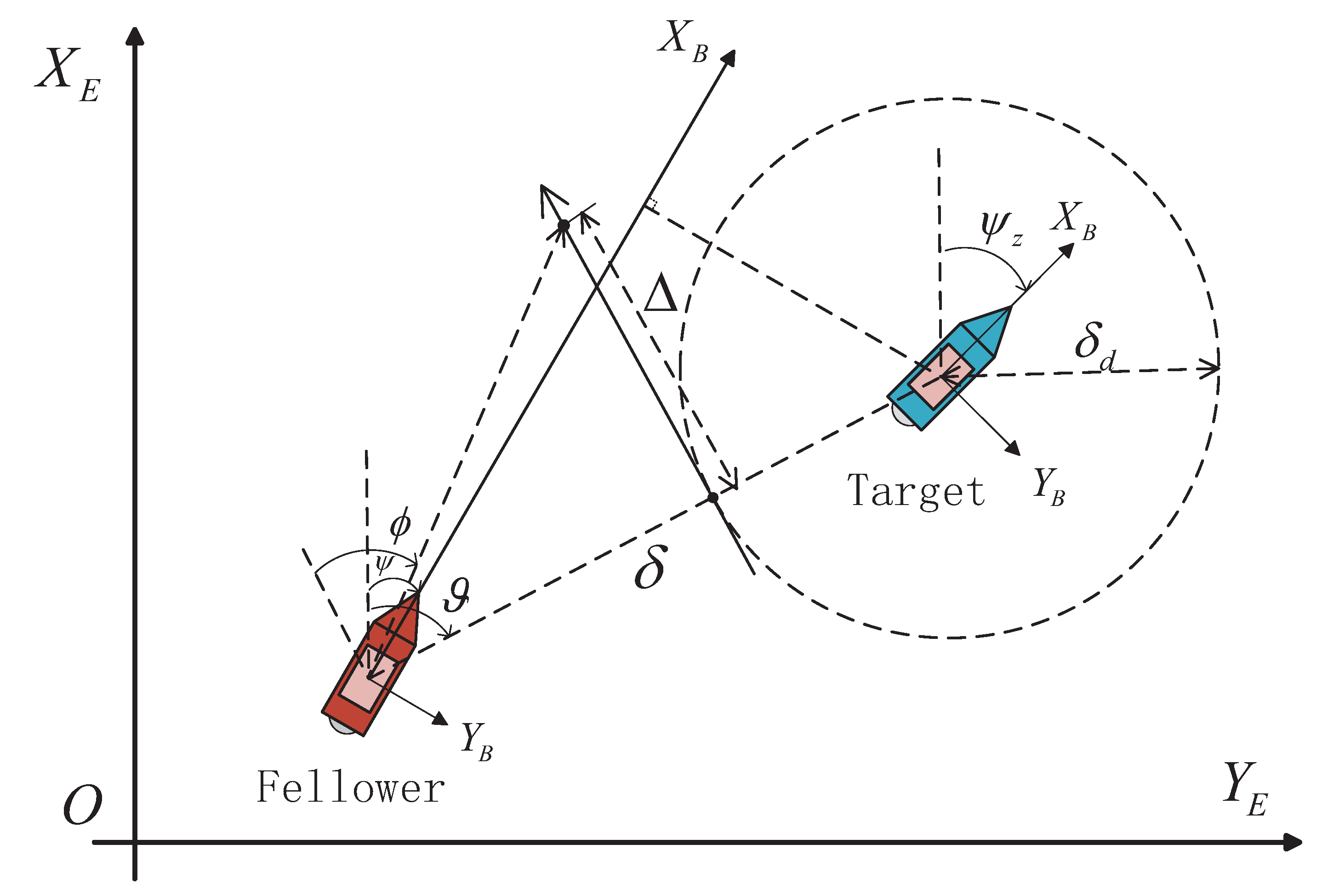
Consider an unmanned boat system consisting of an underdriven following USV and a target USV, which is shown in Figure 2. The kinematics of the target USV can be described as:
x ˙ c = u c cos ψ c v c sin ψ c y ˙ c = u c sin ψ c + v c cos ψ c ψ ˙ c = r c
The relative distance δ and the relative angle ϑ between the following USV and the target USV are defined as:
δ = ( x c x ) 2 + ( y c y ) 2 ϑ = atan 2 ( y c y , x c x )
The angle of encirclement ϕ is defined as the angle between the surge direction of the follower USV and the direction of the straight line connecting the two USVs. It is mapped into the interval ( π , π ] as:
ϕ = ψ ϑ + π 2 π
Taking the time derivatives of (10)–(15), the relative distance rate δ ˙ and relative angle rate ϑ ˙ can be expressed as:
δ ˙ = u z sin ϑ + v z cos ϑ ϑ ˙ = σ ϕ + r
where u z , v z and σ ϕ are defined as:
u z = u c cos ( ψ c ψ ) v c sin ( ψ c ψ ) u v z = u c sin ( ψ c ψ ) + v c cos ( ψ c ψ ) v σ ϕ = 1 δ u cos ϕ v sin ϕ u c cos ( ψ c ( ψ ϕ ) ) + v c sin ( ψ c ( ψ ϕ ) )
Note that u z and v z denote the linear velocities of the target USV relative to the following USV along the longitudinal and lateral directions, respectively, expressed in the body-fixed frame of the following USV. To realize the surround control of a single following USV around the target USV, the distance tracking error and surround angle error are defined as:
δ e = δ δ d ϕ e = ϕ ϕ d
where δ d is the desired surrounding distance, and ϕ d is the desired circling angle designed in the guidance law.
For the underactuated USV described by the kinematic Equation (10) and the dynamic Equation (11), a target encircling controller is designed to enable the follower USV to circle around the target USV at a given desired radius and direction. The control objective is to ensure the convergence of the distance tracking error and surround angle tracking error, such that
lim t δ e ε δ , lim t ϕ e ε ϕ
where ε δ and ε ϕ are small constants.

3. FTTELOS Guidance System Design

In this section, the design of the USV velocity, lumped unknown disturbances, and unknown state observer is presented. In addition, the FTTELOS guidance law proposed in this paper is introduced. It is further proved that both the observer and the proposed guidance subsystem possess fixed-time stability.

3.1. Observer Design

The kinematic equations of the follower unmanned surface vehicle (USV) are described as follows:
η ˙ = R ( ψ ) v
where η = [ x , y , ψ ] T is the position and heading vector in the inertial coordinate frame, v = [ u , v , r ] T is the velocity vector in the body-fixed frame, and R ( ψ ) is the rotation matrix defined by the heading angle ψ .
The following fixed-time velocity observer is designed:
v ^ ˙ = R 1 ( ψ ) μ 1 ε + μ 2 sig α v ( ε ) + μ 3 sig β v ( ε ) + μ 4 sign ( ε )
Let μ i R 3 × 3 ( i = 1 , 2 , 3 , 4 ) be positive definite matrices to be designed. The diagonal elements of μ 4 are chosen to be larger than the corresponding upper bounds of R ( ψ ) v . The constants α v and β v are positive and satisfy 0 < α v < 1 , β v > 1 . Let ε be an auxiliary variable, defined as:
ε = η ω ω ˙ = μ 1 ε + μ 2 sig α v ( ε ) + μ 3 sig β v ( ε ) + μ 4 sign ( ε )
Define the velocity observation error as v ˜ = v v ^ . Taking the derivative of the auxiliary variable ε , we obtain:
ε ˙ = R ( ψ ) v μ 1 ε μ 2 sig α v ( ε ) μ 3 sig β v ( ε ) μ 4 sign ( ε )
Theorem 1. 
Under the given parameter conditions, the observer designed in (21) can accurately estimate the velocity state of the USV within a fixed time. Moreover, the estimation error converges to zero.
Proof. 
Define the following Lyapunov function:
V 1 = 1 2 ε T ε
Taking the derivative of (24), we obtain:
V ˙ 1 = ε T ε ˙ = ε T R ( ψ ) v μ 1 ε μ 2 sig α v ( ε ) μ 3 sig β v ( ε ) μ 4 sign ( ε ) ε T μ 1 ε ε T μ 2 sig α v ( ε ) ε T μ 3 sig β v ( ε ) λ min ( μ 1 ) ε 2 λ min ( μ 2 ) ε 1 + α v λ min ( μ 3 ) ε 1 + β v λ min ( μ 2 ) ( 2 V 1 ) 1 + α v 2 λ min ( μ 3 ) ( 2 V 1 ) 1 + β v 2 = 2 1 + α v 2 λ min ( μ 2 ) V 1 1 + α v 2 2 1 + β v 2 λ min ( μ 3 ) V 1 1 + β v 2 = Ξ v 1 V 1 1 + α v 2 Ξ v 2 V 1 1 + β v 2
where Ξ v 1 = 2 1 + α v 2 λ min ( μ 2 ) and Ξ v 2 = 2 1 + β v 2 λ min ( μ 3 ) . Since 0 < α v < 1 , β v > 1 , it follows that 0 < 1 + α v 2 < 1 and 1 + β v 2 > 1 . □
According to Lemma 1, the auxiliary variable ε is fixed-time stable, and the convergence time T 1 satisfies:
T 1 T 1 max : = 2 Ξ v 1 ( 1 α v ) + 2 Ξ v 2 ( β v 1 )
From Equation (23), once ε converges to zero within a fixed time, the velocity estimation error v ˜ will also converge simultaneously. Based on the definition of V 1 , when t T 1 , we have ε 0 and ε ˙ 0 . Therefore, it follows that:
v ˜ = 0 , t T 1
Similar to the design principle of the velocity observer, a fixed-time lumped uncertainty observer is proposed. The dynamic equation of the USV (21) is rewritten as:
v ˙ = F + M 1 τ
The fixed-time lumped uncertainty observer is designed as:
F ^ = σ 1 ζ + σ 2 sig α f ( ζ ) + σ 3 sig β f ( ζ ) + σ 4 sign ( ζ )
where σ i R 3 × 3 ( i = 1 , 2 , 3 , 4 ) are positive definite gain matrices to be designed. The diagonal elements of σ 4 are chosen to be larger than the upper bounds of the corresponding elements in F . The constants α f and β f are positive and satisfy 0 < α f < 1 , β f > 1 . Let ζ be the auxiliary variable, defined as:
ζ = v ^ φ φ ˙ = σ 1 ζ + σ 2 sig α f ( ζ ) + σ 3 sig β f ( ζ ) + σ 4 sign ( ζ ) + M 1 τ
According to Theorem 1, when the system reaches t T 1 , v = v ^ . The lumped uncertainty observation error is defined as F ˜ = F F ^ . Taking the derivative of the auxiliary variable ζ yields:
ζ ˙ = F σ 1 ζ σ 2 sig α f ( ζ ) σ 3 sig β f ( ζ ) σ 4 sign ( ζ ) = F ˜
Theorem 2. 
Suppose the designed parameters satisfy certain conditions. Then, the observer in (29) guarantees that the lumped uncertainty information of the USV can be accurately estimated within a fixed time interval, and the estimation error converges to zero.
Proof. 
Define the following Lyapunov function:
V 2 = 1 2 ζ T ζ
Taking the derivative of (32), we obtain:
V ˙ 2 = ζ T ζ ˙ = ζ T F σ 1 ζ σ 2 sig α f ( ζ ) σ 3 sig β f ( ζ ) σ 4 sign ( ζ ) ζ T σ 1 ζ ζ T σ 2 sig α f ( ζ ) ζ T σ 3 sig β f ( ζ ) λ min ( σ 1 ) ζ 2 λ min ( σ 2 ) ζ 1 + α f λ min ( σ 3 ) ζ 1 + β f λ min ( σ 2 ) ( 2 V 2 ) 1 + α f 2 λ min ( σ 3 ) ( 2 V 2 ) 1 + β f 2 = 2 1 + α f 2 λ min ( σ 2 ) V 2 1 + α f 2 2 1 + β f 2 λ min ( σ 3 ) V 2 1 + β f 2 = Ξ F 1 V 2 1 + α f 2 Ξ F 2 V 2 1 + β f 2
where Ξ F 1 = 2 1 + α f 2 λ min ( σ 2 ) , Ξ F 2 = 2 1 + α f 2 λ min ( σ 3 ) . Based on Lemma 1, the auxiliary variable ζ converges in fixed time, and the convergence time T 2 satisfies:
T 2 T 2 max : = 2 Ξ F 1 ( 1 α f ) + 2 Ξ F 2 ( β f 1 )
Along (16)–(18) and (21), the derivatives of the distance error and the angular error are expressed by
δ ˙ e = U z sin ( ϕ + θ z ) ϕ ˙ e = σ ϕ + r ^ ϕ ˙ d
where
U z = u z 2 + v z 2 θ z = atan2 ( v z , u z )
The relative distance between the target and following vehicles is defined as:
δ u = δ cos ( β ψ ) δ v = δ sin ( β ψ )
According to (6) and (7), one has
δ ˙ u = u z + δ v r ^ δ ˙ v = v z δ u r ^ ϕ ˙ = σ ϕ + r ^
With the aid of the velocity observer in (21), (17) is reformulated as:
u z = u c cos ( ψ c ψ ) v c sin ( ψ c ψ ) u ^ v z = u c sin ( ψ c ψ ) + v c cos ( ψ c ψ ) v ^ σ ϕ = 1 δ u ^ cos ϕ v ^ sin ϕ u c cos ( ψ c ( ψ ϕ ) ) + v c sin ( ψ c ( ψ ϕ ) )
Since the energy to drive USV and the disturbances in the marine environment are limited, the following hypothesis is proposed:
Assumption 2. 
The derivatives of u z , v z , and σ ϕ in (39) are all bounded, meaning that there exists a constant σ ¯ z R + such that u ˙ z v ˙ z σ ˙ ϕ T σ ¯ z .
Design a set of fixed-time extended state observers to estimate the unknown kinematic states u z , v z , and σ ϕ of the unmanned boat using δ u , δ v , ϕ and r ^ .
δ ^ ˙ u = k 1 sig α ( z 1 ) k 2 sig β ( z 1 ) + u ^ z + δ v r ^ u ^ ˙ z = k 3 sig γ ( z 1 ) k 4 sig δ ( z 1 ) δ ^ ˙ v = k 5 sig α ( z 3 ) k 6 sig β ( z 3 ) + v ^ z δ u r ^ v ^ ˙ z = k 7 sig γ ( z 3 ) k 8 sig δ ( z 3 ) ϕ ^ ˙ = k 9 sig α ( z 5 ) k 10 sig β ( z 5 ) + σ ^ ϕ + r ^ σ ^ ˙ ϕ = k 11 sig γ ( z 5 ) k 12 sig δ ( z 5 )
Define the estimation errors as:
z 1 = δ ^ u δ u , z 2 = u ^ z u z , z 3 = δ ^ v δ v , z 4 = v ^ z v z , z 5 = ϕ ^ ϕ , z 6 = σ ^ ϕ σ ϕ .
Here, δ ^ u , δ ^ v , and ϕ ^ denote the estimates of the measurable states δ u , δ v , and ϕ , respectively, while u ^ z , v ^ z , and σ ^ ϕ represent the estimates of the unknown disturbances u z , v z , and σ ϕ . The observer gains satisfy k j R + for j = 1 , 2 , , 12 .
z ˙ 1 = δ ^ ˙ u δ ˙ u = κ 1 sig α ( z 1 ) κ 2 sig β ( z 1 ) + z 2 z ˙ 2 = u ^ ˙ z u ˙ z = κ 3 sig γ ( z 1 ) κ 4 sig δ ( z 1 ) u ˙ z z ˙ 3 = δ ^ ˙ v δ ˙ v = κ 5 sig α ( z 3 ) κ 6 sig β ( z 3 ) + z 4 z ˙ 4 = v ^ ˙ z v ˙ z = κ 7 sig γ ( z 3 ) κ 8 sig δ ( z 3 ) v ˙ z z ˙ 5 = ϕ ^ ˙ ϕ ˙ = κ 9 sig α ( z 5 ) κ 10 sig β ( z 5 ) + z 6 z ˙ 6 = σ ^ ˙ ϕ σ ˙ ϕ = κ 11 sig γ ( z 5 ) κ 12 sig δ ( z 5 ) σ ˙ ϕ
Theorem 3. 
Suppose the designed parameters satisfy certain conditions. Then, the HFTESO (40) can accurately estimate the unknown states of the system within a fixed time, and the estimation error converges to zero.
Proof. 
Define the following Lyapunov function:
V 3 = V f 1 + V f 2 + V f 3
where V f 1 = 1 2 ( z 1 2 + z 2 2 ) , V f 2 = 1 2 ( z 3 2 + z 4 2 ) , V f 3 = 1 2 ( z 5 2 + z 6 2 ) .
V ˙ f 1 = z 1 z ˙ 1 + z 2 z ˙ 2 = z 1 k 1 | z 1 | α sign ( z 1 ) k 2 | z 1 | β sign ( z 1 ) + z 2 + z 2 k 3 | z 1 | γ sign ( z 1 ) k 4 | z 1 | δ sign ( z 1 ) u ˙ z = k 1 | z 1 | α + 1 k 2 | z 1 | β + 1 + z 1 z 2 k 3 z 2 | z 1 | γ sign ( z 1 ) k 4 z 2 | z 1 | δ sign ( z 1 ) z 2 u ˙ z k 1 | z 1 | α + 1 k 2 | z 1 | β + 1 + | z 1 | | z 2 | k 3 | z 2 | | z 1 | γ k 4 | z 2 | | z 1 | δ + | z 2 | Δ u k 1 2 1 + α 2 V f 1 1 + α 2 k 2 2 1 + β 2 V f 1 1 + β 2 + V f 1 + Δ u 2 V f 1 1 2 = c 1 , 1 V f 1 1 + α 2 c 1 , 2 V f 1 1 + β 2 + ϵ f 1
Similar to V f 1 , define the second and third Lyapunov functions:
V ˙ f 2 = z 3 z ˙ 3 + z 4 z ˙ 4 c 2 , 1 V f 2 1 + α 2 c 2 , 2 V f 2 1 + β 2 + ϵ f 2
V ˙ f 3 = z 5 z ˙ 5 + z 6 z ˙ 6 c 3 , 1 V f 3 1 + α 2 c 3 , 2 V f 3 1 + β 2 + ϵ f 3
By summing the derivatives of the three individual Lyapunov functions, the total Lyapunov function V 3 = V f 1 + V f 2 + V f 3 satisfies:
V ˙ 3 = V ˙ f 1 + V ˙ f 2 + V ˙ f 3 a 1 V 3 1 + α 2 a 2 V 3 1 + β 2 + ϵ
where the decay coefficients are defined as
a 1 = min { c 1 , 1 , c 2 , 1 , c 3 , 1 } , a 2 = min { c 1 , 2 , c 2 , 2 , c 3 , 2 } , and ϵ = ϵ f 1 + ϵ f 2 + ϵ f 3 .
According to Lemma 2, z 2 , z 4 and z 6 will converge to zero in fixed time, and the convergence time T 3 satisfies:
T 3 T 3 max : = 2 a 1 θ ( 1 α ) + 2 a 2 θ ( β 1 )
where 0 < θ < 1 .
Moreover, the convergence set of V 3 ( x ) satisfies:
lim t T 3 x | V 3 ( x ) min a 1 1 α ϵ 1 θ 1 α , a 2 1 β ϵ 1 θ 1 β

3.2. FTTELOS Guidance Law Design

This part will give the designed FTTELOS guidance law, which includes heading angle guidance law and surge velocity guidance law. On the basis of FTTELOS guidance law, δ e , ϕ e can converge to a small neighborhood of the origin within a fixed-time interval, and Lyapunov stability analysis will be given in this part.
Using the estimator, (35) can be written as:
δ ˙ e = U ^ z sin ( ϕ + θ ^ z ) ϕ ˙ e = σ ^ ϕ + r ^ ϕ ˙ d
where
U ^ z = u ^ z 2 + v ^ z 2 θ ^ z = atan2 ( v ^ z , u ^ z )
The FTTELOS guidance law is formulated as follows:
r d = k r ϕ e σ ^ ϕ r ^ + ϕ ˙ d ξ g ϕ d = arctan δ e + ξ f Δ θ ^ z u d = k u 1 u d m i n 2 + k u 2 δ e 2
where r d and u d are the desired heading angle and surge velocity, ξ g and ξ f are the fixed-time auxiliary term, which is designed as ξ f = ( λ 1 sig m ( δ e ) + λ 2 sig n ( δ e ) δ e ) / cos ( ϕ e ) , ξ g = λ 3 sig m ( ϕ e ) + λ 4 sig n ( ϕ e ) k r ϕ e , and λ i ( i = 1 , 2 , 3 , 4 ) , k r , k u 1 , k u 2 are positive constants.
The objective of designing r d is to ensure the convergence of the distance tracking error δ e and the encircling angle tracking error ϕ e . Meanwhile, the control input u d is designed to accelerate the USV’s motion toward the desired encircling behavior. In (52), Δ represents the look-ahead distance. A larger value of Δ allows the USV to make more proactive heading adjustments and converge faster toward the target orbit, but it may also lead to overshoot or instability, especially near the target. Conversely, a smaller Δ improves local tracking accuracy but slows down the convergence speed. To balance this trade-off, a smooth adaptive update law for Δ is proposed in this paper, which adjusts its value dynamically based on the encircling error. The update law is given as follows:
Δ = Δ min + ( Δ max Δ min ) · | δ e | h | δ e | h + c h
where Δ min and Δ max define the minimum and maximum values of the look-ahead distance, c is the error balance factor that determines the threshold for significant change, and h adjusts the steepness of the curve.
According to (52), the dynamic equation of the encircling distance error δ e can be rewritten as:
δ ˙ e = U ^ z δ e 2 + Δ 2 ( sin ( ϕ e ) Δ + cos ( ϕ e ) ( δ e + ξ f ) ) = k δ δ e + H ( δ e , ϕ e ) ϕ e k δ cos ( ϕ e ) ξ f = k δ δ e + H ( δ e , ϕ e ) ϕ e k δ ( λ 1 sig m ( δ e ) + λ 2 sig n ( δ e ) δ e ) = H ( δ e , ϕ e ) ϕ e k δ ( λ 1 sig m ( δ e ) + λ 2 sig n ( δ e ) )
where H ( δ e , ϕ e ) = ( sin ( ϕ e ) ϕ e Δ δ e 2 + Δ 2 cos ( ϕ e ) 1 ϕ e δ e δ e 2 + Δ 2 ) U ^ z From sin ( ϕ e ) / ϕ e 1 and cos ( ϕ e ) 1 / ϕ e 0.73 , we get: H ( δ e , ϕ e ) H max 1.73 U ^ z and k δ = U ^ z / δ e 2 + Δ 2 .
The dynamic equation of the encircling angle error ϕ e can be rewritten as:
ϕ ˙ e = λ 3 sig m ( ϕ e ) λ 4 sig n ( ϕ e )
Theorem 4. 
Based on the FTTELOS guidance law presented in (52), both δ e and ϕ e converge to a small neighborhood around the origin within a fixed-time interval.
Proof. 
Define the following Lyapunov function:
V 4 = 1 2 δ e 2 + 1 2 ϕ e 2
By differentiating V 4 and substituting Equations (54) and (55), the following expression is obtained:
V ˙ 4 = δ e δ ˙ e + ϕ e ϕ ˙ e = δ e ( H ( δ e , ϕ e ) ϕ e k δ ( λ 1 sig m ( δ e ) + λ 2 sig n ( δ e ) ) ) + ϕ e ( λ 3 sig m ( ϕ e ) λ 4 sig n ( ϕ e ) ) = H ( δ e , ϕ e ) δ e ϕ e k δ λ 1 | δ e | m + 1 k δ λ 2 | δ e | n + 1 λ 3 | ϕ e | m + 1 λ 4 | ϕ e | n + 1 k δ λ 1 | δ e 2 | m + 1 2 λ 3 | ϕ e 2 | m + 1 2 k δ λ 2 | δ e 2 | n + 1 2 λ 4 | ϕ e 2 | n + 1 2 + 1.73 U ^ z δ e ϕ e k δ λ 1 2 m + 1 2 ( 1 2 δ e 2 ) m + 1 2 λ 3 2 m + 1 2 ( 1 2 ϕ e 2 ) m + 1 2 k δ λ 2 2 n + 1 2 ( 1 2 δ e 2 ) n + 1 2 λ 4 2 n + 1 2 ( 1 2 ϕ e 2 ) n + 1 2 + 1.73 U ^ z 2 δ e 2 + 1.73 U ^ z 2 ϕ e 2 μ 1 V 4 m + 1 2 μ 2 V 4 n + 1 2 + ϵ 1
where μ 1 = min { k δ λ 1 2 m + 1 2 , λ 3 2 m + 1 2 } , μ 2 = min { k δ λ 2 2 n + 1 2 , λ 4 2 n + 1 2 } , ϵ 1 = 1.73 U ^ z 2 δ e 2 + 1.73 U ^ z 2 ϕ e 2 .
According to Lemma 2, δ e and ϕ e will converge to zero in fixed time, and the convergence time T 4 satisfies:
T 4 T 4 max : = 2 μ 1 θ 1 ( 1 m ) + 2 μ 2 θ 1 ( n 1 )
where 0 < θ 1 < 1 .
Moreover, the convergence set of V 4 ( x ) satisfies:
lim t T 4 x ( t ) | V 4 ( x ) min μ 1 1 m ϵ 1 1 θ 1 1 m , μ 2 1 n ϵ 2 1 θ 1 1 n

4. Target Encircling Controller Design

The control subsystem plays a critical role in ensuring that the heading angle ψ and speed u of the Unmanned Surface Vehicle (USV) accurately track the reference values generated by the FTTELOS guidance law. To achieve precise target encircling, it is essential to design a highly robust controller. To this end, this paper proposes a fixed-time sliding mode controller with a fixed-threshold event-triggering mechanism, which integrates fixed-time sliding mode control theory, a fixed-time auxiliary saturation system, and a fixed-threshold event-triggering strategy. The detailed design and analysis are presented as follows.

4.1. Design of an FTSM-Based Surge Controller

The fixed-time sliding surface is designed as follows:
S u = e u + 0 t λ u 1 sig a s ( e u ( τ u ) ) + λ u 2 sig b s ( e u ( τ u ) ) d τ u
where λ u i ( i = 1 , 2 ) are the positive control parameters to be designed, with 0 < a s < 1 and 1 < b s . When the velocity error variables reach the sliding surface, S u = 0 we have:
e ˙ u = λ u 1 sig a s ( e u ) λ u 2 sig b s ( e u )
Taking the derivative of both sides of (60), we obtain:
S ˙ u = e ˙ u + λ u 1 sig a s ( e u ) + λ u 2 sig b s ( e u ) = F ^ u + ( τ u ) / m 11 u ˙ d + λ u 1 sig a u ( e u ) + λ u 2 sig b u ( e u )
To accelerate the convergence speed to the sliding surface and avoid chattering caused by conventional sliding mode control, a fixed-time sliding mode reaching law based on the Gaussian error function is designed as follows:
S ˙ u = 1 Ξ ( S u ) α u 1 sig n 1 ( S u ) + α u 2 sig n 1 / ( n 1 + 1 ) ( S u )
Ξ ( S u ) = ω 3 1 ω 1 erf ( ω 2 | S u | )
where α u 1 and α u 2 are positive design parameters, 0 < ω 1 , ω 2 < 1 , 1 < ω 3 .
In (64), the function Ξ ( S u ) is always a positive number, so it does not affect the stability of the system. When the value of | S u | is large, appropriate values of ω 1 and ω 2 can ensure that ω 1 erf ( ω 2 | S u | ) 1 , which leads to Ξ ( S u ) ω 3 > 1 , and hence 1 / Ξ ( S u ) < 1 , thus improving the convergence speed of the system under this reaching law. Conversely, when | S u | is small, suitable choices of ω 1 and ω 2 can ensure that ω 1 erf ( ω 2 | S u | ) 0 , yielding Ξ ( S u ) ω 3 > 1 and 1 / Ξ ( S u ) < 1 , which effectively suppresses control chattering.
The surge control law is designed as:
τ u = m 11 ( u ˙ d F ^ u λ u 1 sig a s ( e u ) λ u 2 sig b s ( e u ) ) m 11 ( α u 1 sig n 1 ( S u ) + α u 2 sig 1 / n 1 ( S u ) Ξ ( S u ) ) + κ u Φ u
The auxiliary saturation terms Φ u is introduced to eliminate the effects caused by input saturation. It defined as:
Φ ˙ u = S u Δ τ u m 11 + n 1 n 1 + 1 b u | Φ u | n 1 + 1 n 1 + | Δ τ u | n 1 + 1 n 1 Φ u Γ ( Φ u ) l u sig n 1 ( Φ u ) + Δ τ u
where Δ τ r = τ r τ c r .
The piecewise continuous smoothing function Γ ( · ) is defined as follows:
Γ ( Φ ) = 0 , | Φ | | Φ a | 1 cos ( π 2 sin ( π 2 Φ 2 Φ a 2 Φ b 2 Φ a 2 ) ) , | Φ a | < | Φ | < | Φ b | 1 , | Φ | | Φ b |
where Φ a and Φ b are two small positive constants satisfying Φ b > Φ a .

4.2. Design of an FTSM-Based Heading Controller

The fixed-time sliding surface is designed as follows:
S r = e r + 0 t λ r 1 sig a s ( e r ( τ r ) ) + λ r 2 sig b s ( e r ( τ r ) ) d τ r
where λ r i ( i = 1 , 2 ) are the positive control parameters to be designed, with 0 < a s < 1 and 1 < b s . When the velocity error variables reach the sliding surface, S r = 0 we have:
e ˙ u = λ r 1 sig a s ( e r ) λ r 2 sig b s ( e r )
Taking the derivative of both sides of (68), we obtain:
S ˙ r = e ˙ r + λ r 1 sig a s ( e r ) + λ r 2 sig b s ( e r ) = F ^ r + ( τ r / m 33 r ˙ d + λ r 1 sig a s ( e r ) + λ u 2 sig b s ( e r )
To accelerate the convergence speed to the sliding surface and avoid chattering caused by conventional sliding mode control, a fixed-time sliding mode reaching law based on the Gaussian error function is designed as follows:
S ˙ r = 1 Ξ ( S r ) α r 1 sig n 1 ( S r ) + α r 2 sig n 1 / ( n 1 + 1 ) ( S r )
Ξ ( S r ) = ω 3 1 ω 1 erf ( ω 2 | S r | )
where α r 1 and α r 2 are positive design parameters, 0 < ω 1 , ω 2 < 1 , 1 < ω 3 .
In (72), the function Ξ ( S r ) is always a positive number, so it does not affect the stability of the system. When the value of | S r | is large, appropriate values of ω 1 and ω 2 can ensure that ω 1 erf ( ω 2 | S r | ) 1 , which leads to Ξ ( S r ) ω 3 > 1 , and hence 1 / Ξ ( S r ) < 1 , thus improving the convergence speed of the system under this reaching law. Conversely, when | S r | is small, suitable choices of ω 1 and ω 2 can ensure that ω 1 erf ( ω 2 | S r | ) 0 , yielding Ξ ( S r ) ω 3 > 1 and 1 / Ξ ( S r ) < 1 , which effectively suppresses control chattering.
The heading control law is designed as:
τ r = m 33 ( r ˙ d F ^ r λ r 1 sig a s ( e r ) λ r 2 sig b s ( e r ) ) m 33 ( α r 1 sig n 1 ( S r ) + α r 2 sig 1 / n 1 ( S r ) Ξ ( S r ) ) + κ r Φ r
The auxiliary saturation terms Φ r is introduced to eliminate the effects caused by input saturation. It defined as:
Φ ˙ r = S r Δ τ r m 33 + n 1 n 1 + 1 b r | Φ r | n 1 + 1 n 1 + | Δ τ r | n 1 + 1 n 1 Φ r Γ ( Φ r ) l r s i g n 1 ( Φ r ) + Δ τ r
where Δ τ r = τ r τ c r .

4.3. Design of the Differentiator

In the process of designing the dynamic control law, it is necessary to obtain the first-order derivatives of ϕ d , u d , and r d . However, directly differentiating these signals may lead to the problem of “differentiation explosion,” which can adversely affect the control system. To avoid this, the following fixed-time differentiator is introduced:
z ˙ d d = z d f + k z 1 s i g p 1 ( z d z d d ) + K z 1 s i g q 1 ( z d z d d ) + ϕ 1 sign ( z d z d d ) z ˙ d f = k z 2 s i g p 2 ( z d z d d ) + K z 2 s i g q 2 ( z d z d d ) + ϕ 2 s i g n ( z d z d d )
where z 1 d = [ ϕ d , u d , r d ] T represents the desired signals generated by the guidance or virtual control law. z d d = [ ϕ d d , u d d , r d d ] T denotes the estimated values of the desired signals, and z d f = [ ϕ d f , u d f , r d f ] T represents the estimated first-order derivatives of these signals. The parameters are selected based on the following principles: 2 3 < p 1 < 1 , p 2 = 2 p 1 1 , q 1 = 1 p 1 , q 2 = p 1 + 1 p 1 1 . k z 1 , k z 2 , K z 1 , K z 2 , ϕ 1 , ϕ 2 R 3 × 3 are positive definite matrices to be designed.
Theorem 5. 
When the designed parameters satisfy the given conditions, the proposed fixed-time differentiator (75) can accurately estimate ϕ d , u d , and r d and their first-order derivatives within a fixed-time interval, and the estimation errors converge to zero.
Define the estimation errors as z ˜ d = z d z d d , z ˜ ˙ d = z ˙ d z d f , In this chapter, the convergence time of the differentiator estimation errors to zero is denoted as T z . The correctness of Theorem 5 has been proven in [43] and will not be repeated here
The (65) and (73) are rewritten by incorporating the differentiator as follows:
τ u = m 11 ( u d f F u λ u 1 sig a s ( e u ) λ u 2 sig b s ( e u ) ) m 11 ( α u 1 sig n 1 ( S u ) + α u 2 sig 1 / n 1 ( S u ) Ξ ( S u ) ) + κ u Φ u
τ r = m 33 ( r d f F r λ r 1 sig a s ( e r ) λ r 2 sig b s ( e r ) ) m 33 ( α r 1 sig n 1 ( S r ) + α r 2 sig 1 / n 1 ( S r ) Ξ ( S r ) ) + κ r Φ r

4.4. Design of a Fixed-Threshold Event-Triggered Controller

The fixed-threshold event-triggered controller is designed as follows:
τ c i ( t ) = ω i ( t k ) , t [ t k , t k + 1 ) t k + 1 = inf t R | e i 2 m i
Then, the measurement error is defined as:
e i 2 ( t ) = ω i ( t ) τ c i ( t ) , t [ t k , t k + 1 )
Here, t k represents the updating instant of the triggering mechanism, inf { · } denotes the infimum, and m i > 0 ( i = u , r ) is the designed fixed triggering threshold.
In the event-triggered control strategy, ω i ( t k ) represents the controller value at the previous triggering instant, and τ c i ( t ) keeps the value ω i ( t k ) via a zero-order holder during t [ t k , t k + 1 ) , until the next triggering instant t k + 1 .
The fixed-threshold triggering law ω i ( t k ) is defined as:
ω i ( t k ) = τ i m i tanh m i S i μ i
where μ i > 0 , i = u , r . when at the k-th triggering instant, t [ t k , t k + 1 ) , it follows from (78) that | ω i ( t ) τ c i ( t ) | m i .
Therefore, there exists a continuous time-varying parameter θ i ( t ) such that ω i ( t ) = τ c i ( t ) + θ i ( t ) m i , and the parameter θ i ( t ) satisfies: θ i ( t k ) = 0 , θ i ( t k + 1 ) = ± 1 , t [ t k , t k + 1 ) .
Thus, we have:
τ c i ( t ) = ω i ( t ) θ i ( t ) m i
According to Lemma 3, and combining (80) and (81), we obtain:
S i τ c i = S i τ i m i tanh m i S i μ i θ i ( t ) m i S i τ i + 0.2785 μ i

4.5. Stability Analysis

Theorem 6. 
Suppose the designed parameters satisfy the given conditions. Under the control laws (76) and (77), the system dynamic errors e u , e r and auxiliary variables Φ u , Φ r will converge within a fixed time interval, and the estimation errors will reach zero.
Remark 2. 
The global fixed-time stability established in Theorems 3–6 relies on the following assumptions: (i) the system states, disturbances, and their derivatives are bounded; (ii) the control gains, and the auxiliary parameters in the fixed-time observers satisfy the inequalities required by Lemma, which guarantee that the Lyapunov function derivative is strictly negative definite within a finite time. Under these conditions, all estimation and tracking errors converge to an arbitrarily small neighborhood of the origin within a fixed time, independent of the initial conditions.
Remark 3. 
The actuator saturation problem is effectively addressed by introducing a bounded auxiliary dynamic system and a fixed-threshold event-triggered mechanism. The auxiliary term Φ u (and Φ r ) dynamically compensates for excessive control effort, ensuring that the actual input τ remains within its physical limits.
Proof. 
Define the following Lyapunov function:
V 5 = 1 2 S u 2 + S r 2 + Φ u 2 + Φ r 2
The derivative of the above equation yields:
V ˙ 5 = S u S ˙ u + S r S ˙ r + Φ u Φ ˙ u + Φ r Φ ˙ r = S u ( F u + Δ τ u + τ c u m 11 u ˙ d + λ u 1 s i g a s ( e u ) + λ u 2 s i g b s ( e u ) ) + S r ( F r + Δ τ r + τ c r m 33 r ˙ d + λ r 1 s i g a s ( e r ) + λ r 2 s i g b s ( e r ) ) + Φ u Φ ˙ u + Φ r Φ ˙ r
Then we obtain:
V ˙ 5 S u ( F u F ^ u + u d f u ˙ d + Δ τ u m 11 α u 1 s i g n 1 ( S u ) + α u 2 s i g 1 / n 1 ( S u ) Ξ ( S u ) + κ u Φ u m 11 ) + S r ( F r F ^ r + r d f r ˙ d + Δ τ r m 33 α r 1 s i g n 1 ( S r ) + α r 2 s i g 1 / n 1 ( S r ) Ξ ( S r ) + κ r Φ r m 33 ) + 0.2785 m 11 μ u + 0.2785 m 33 μ r + Φ u Φ ˙ u + Φ r Φ ˙ r
According to (30) and (75), when t max { T 2 , T z } , it holds that i d f = i ˙ d , F i = F ^ r ( i = u , r ). The above equation can then be simplified as:
V ˙ 5 S u ( Δ τ u m 11 α u 1 s i g n 1 ( S u ) + α u 2 s i g 1 / n 1 ( S u ) Ξ ( S u ) + κ u Φ u m 11 ) + S r ( Δ τ r m 33 α r 1 s i g n 1 ( S r ) + α r 2 s i g 1 / n 1 ( S r ) Ξ ( S r ) + κ r Φ r m 33 ) + 0.2785 m 11 μ u + 0.2785 m 33 μ r + Φ u Φ ˙ u + Φ r Φ ˙ r
According to (66) and (74), we obtain:
V ˙ 5 α u 1 Ξ ( S u ) | S u | n 1 + 1 α u 2 Ξ ( S u ) | S u | n 1 + 1 n 1 + κ u m 11 S u Φ u α r 1 Ξ ( S r ) | S r | n 1 + 1 α r 2 Ξ ( S r ) | S r | n 1 + 1 n 1 + κ r m 33 S r Φ r n 1 n 1 + 1 ( b u | Φ u | n 1 + 1 n 1 + | Δ τ u | n 1 + 1 n 1 ) Γ ( Φ u ) n 1 n 1 + 1 ( b r | Φ r | n 1 + 1 n 1 + | Δ τ r | n 1 + 1 n 1 ) Γ ( Φ r ) l u | Φ u | n 1 + 1 + Δ τ u Φ u l r | Φ r | n 1 + 1 + Δ τ r Φ r + 0.2785 m 11 μ u + 0.2785 m 33 μ r
According to Lemma 4, it follows that:
Φ i Δ τ i 1 n 1 + 1 | Φ i | n 1 + 1 + 1 1 / n 1 + 1 | Δ τ i | 1 / n 1 + 1 S i Φ i 1 n 1 + 1 | S i | n 1 + 1 + 1 1 / n 1 + 1 | Φ i | 1 / n 1 + 1
where i = u , r . Combining (88), when Γ ( Φ i ) = 1 ( i = u , r ) , (87) can be simplified as:
V ˙ 5 ( α u 1 Ξ ( S u ) κ u m 11 1 n 1 + 1 ) | S u | n 1 + 1 α u 2 Ξ ( S u ) | S u | n 1 + 1 n 1 ( α r 1 Ξ ( S r ) κ r m 33 1 n 1 + 1 ) | S r | n 1 + 1 α r 2 Ξ ( S r ) | S r | n 1 + 1 n 1 ( n 1 b u n 1 + 1 κ u m 11 n 1 n 1 + 1 ) | Φ u | n 1 + 1 n 1 ( n 1 b r n 1 + 1 κ r m 33 n 1 n 1 + 1 ) | Φ r | n 1 + 1 n 1 ( l u 1 n 1 + 1 ) | Φ u | n 1 + 1 ( l r 1 n 1 + 1 ) | Φ r | n 1 + 1 + 0.2785 m 11 μ u + 0.2785 m 33 μ r
V ˙ 5 2 n 1 + 1 2 ( α u 1 Ξ ( S u ) κ u m 11 1 n 1 + 1 ) | 1 2 S u 2 | n 1 + 1 2 2 n 1 + 1 2 ( l u 1 n 1 + 1 ) | 1 2 Φ u 2 | n 1 + 1 2 2 n 1 + 1 2 ( α r 1 Ξ ( S r ) κ r m 33 1 n 1 + 1 ) | 1 2 S r 2 | n 1 + 1 2 2 n 1 + 1 2 ( l r 1 n 1 + 1 ) | 1 2 Φ r 2 | n 1 + 1 2 2 n 1 + 1 2 n 1 α u 2 Ξ ( S u ) | 1 2 S u 2 | n 1 + 1 2 n 1 2 n 1 + 1 2 n 1 α r 2 Ξ ( S r ) | 1 2 S r 2 | n 1 + 1 2 n 1 2 n 1 + 1 2 n 1 ( n 1 b u n 1 + 1 κ u m 11 n 1 n 1 + 1 ) | 1 2 Φ u 2 | n 1 + 1 2 n 1 + 0.2785 m 11 μ u 2 n 1 + 1 2 n 1 ( n 1 b r n 1 + 1 κ r m 33 n 1 n 1 + 1 ) | 1 2 Φ r 2 | n 1 + 1 2 n 1 + 0.2785 m 33 μ r χ 1 V 5 n 1 + 1 2 χ 2 V 5 n 1 + 1 2 n 1 + ϵ 2
where χ 1 = 2 n 1 + 1 2 min ( α u 1 Ξ ( S u ) κ u m 11 1 n 1 + 1 ) , ( α r 1 Ξ ( S r ) κ r m 33 1 n 1 + 1 ) , [ 1.5 m m ] ( l u 1 n 1 + 1 ) , ( l r 1 n 1 + 1 ) , χ 2 = 2 n 1 + 1 2 n 1 min α u 2 Ξ ( S u ) , α r 2 Ξ ( S r ) , ( n 1 b u n 1 + 1 κ u m 11 n 1 n 1 + 1 ) , ( n 1 b r n 1 + 1 κ r m 33 n 1 n 1 + 1 ) , ϵ 2 = 0.2785 m 11 μ u + 0.2785 m 33 μ r , b u m 11 > κ u , b r m 33 > κ r , l u 1 n 1 + 1 > 0 , l r 1 n 1 + 1 > 0 .
When Γ ( ϕ i ) ( 0 , 1 ) , the analysis is similar and thus omitted. According to Lemma 2, system V 5 will converge to zero in fixed time, and the convergence time T 5 satisfies:
T 5 T 5 max : = 2 χ 1 θ 2 ( n 1 1 ) + 2 n 1 χ 2 θ 2 ( n 1 1 )
where 0 < θ 2 < 1 .
Zeno Behavior Exclusion:To exclude Zeno behavior, it suffices to show that the time interval between any two consecutive triggering instants of the controller, denoted by { t k + 1 t k , k N } , is strictly greater than zero. This ensures that Zeno behavior cannot occur.
From (79), we obtain:
d d t | e i 2 | = sign ( e i 2 ) e ˙ i 2 | ϕ ˙ i ( t ) | .
According to (80), ω i ( t ) is a continuously differentiable function. Since all signals in the closed-loop system are bounded, there exists a constant H > 0 such that | ω i ( t ) | H for all t.
At the triggering instant t = t k , we have e i 2 ( t k ) = 0 . As t t k + 1 , it follows that lim t t k + 1 e i 2 ( t ) = m i .
Hence, the triggering interval must satisfy: { t k + 1 t k m i H } , k N , which implies that Zeno behavior is excluded. □

5. Simulation Results

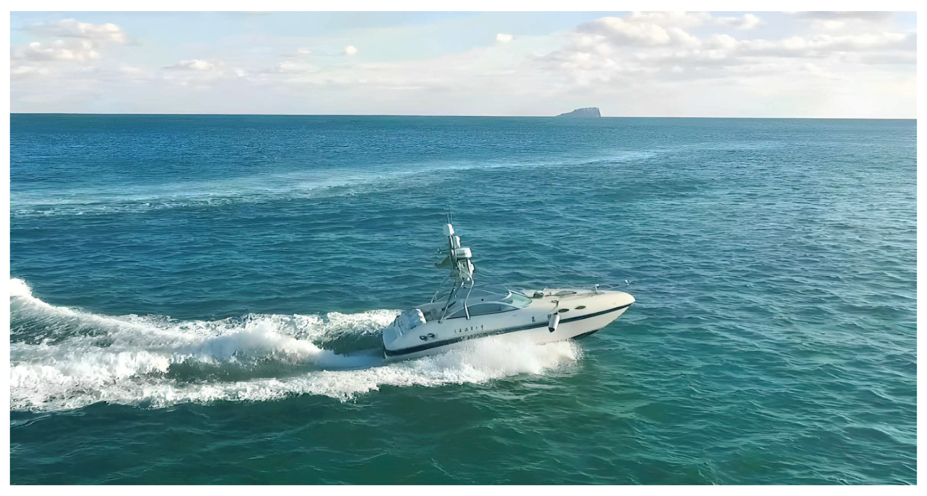
To verify the effectiveness and superiority of the FTDALOS and FTAFC control strategies, simulation studies using SimuNPS (https://www.keliangtek.com/) are conducted on the ‘LanXin’ unmanned surface vehicle (USV), as illustrated in Figure 3. The inertia parameters of the USV are listed as follows: m 11 = 2652.52 kg, m 22 = 2825.57 kg, m 33 = 4201.68 kg, d 11 = 848.13 kg/s, d 22 = 10,162.44 kg/s, d 33 = 22,721.63 kg/s.
The lumped uncertainties are assumed as follows:
D u = 400 ( sin ( 0.2 t + 0.3 π ) + cos ( 0.2 t + 0.3 π ) ) + 800 + 0.1 f u D v = 100 ( sin ( 0.1 t + 0.6 π ) + cos ( 0.1 t + 0.3 π ) ) + 800 + 0.1 f v D r = 400 ( sin ( 0.3 t + 0.6 π ) + cos ( 0.2 t + 0.5 π ) ) + 800 + 0.1 f r
The parameters of the target are set as follows: x c ( 0 ) = 30 m , y c ( 0 ) = 30 m , u c = 1 m / s , ψ c = 1 t / 200 rad / s . and the initial parameters of the follower USV are: x ( 0 ) = 5 m , y ( 0 ) = 3 m , u ( 0 ) = 0 m / s , v ( 0 ) = 0 m / s .
Remark 4. 
SimuNPS provides a modular simulation environment for modeling and testing unmanned surface vehicle (USV) dynamics under various environmental conditions. It allows the implementation of customized controllers, observer structures, and communication modules, enabling rapid verification of algorithmic performance in a controlled and repeatable manner. The platform supports multi-sensor integration, real-time data visualization, and flexible parameter adjustment, which significantly facilitates experimental validation of control schemes before field testing. However, SimuNPS remains a numerical simulator, and certain real-world effects such as sensor noise, actuator latency, and strong hydrodynamic coupling are simplified or omitted. Therefore, while it serves as an efficient tool for verifying theoretical feasibility and robustness, further validation through hardware-in-the-loop or field experiments is still required for practical deployment.
Remark 5. 
In the simulation studies, the error convergence time (or state stabilization time) is defined as the moment when the corresponding variable first enters the range of ±2% of the maximum error or the extreme value of the system state, and subsequently remains within this range without violating it.
Remark 6. 
The hyperparameters listed in Table 1 were determined through a combination of theoretical guidelines and simulation-based fine-tuning. Initially, the control gains were selected to satisfy the sufficient conditions for system stability derived from the Lyapunov analysis, ensuring that the closed-loop system satisfies fixed-time convergence. Subsequently, the observer and controller parameters were iteratively adjusted within a feasible range through numerical simulations in SimuNPS to achieve a desirable balance between convergence speed, chattering suppression, and control smoothness.
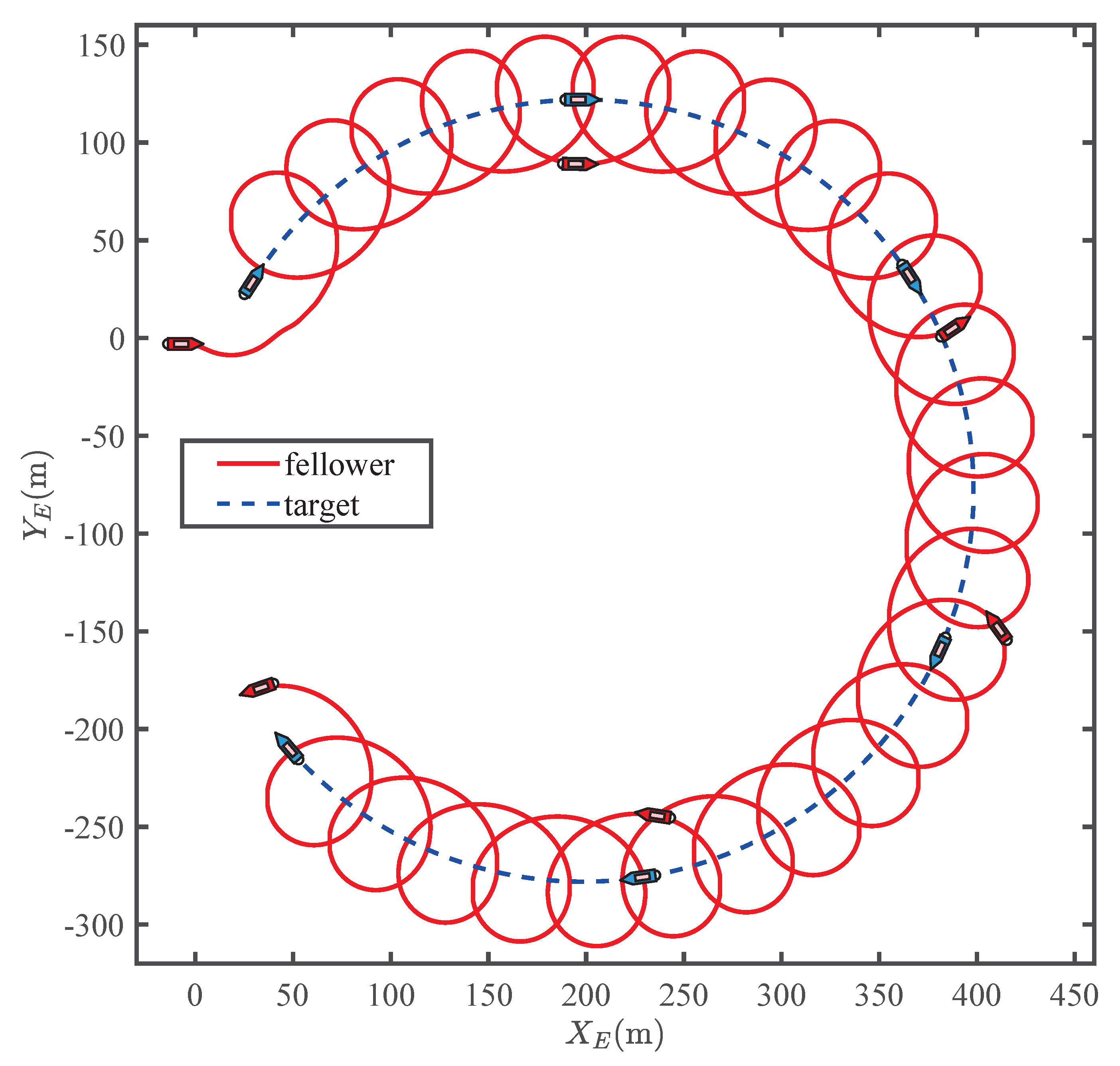
Table 1 lists the control parameters used in the simulation studies. Figure 4 illustrates the simulation results of the USV performing the target enclosing and tracking task using the proposed FTTELOS guidance law and the fixed-threshold event-triggered controller under fixed-time sliding mode control.
To validate the effectiveness and superiority of the proposed FTTELOS guidance law, different guidance laws are employed while keeping the control parameters consistent. Compared with the traditional TELOS guidance law, the FTTELOS demonstrates significantly improved performance in controlling variables δ e and ϕ e . Figure 5 illustrates the convergence performance comparison of δ e and ϕ e under two different guidance laws with the same initial condition. Table 2 lists the specific convergence times ( T c ) of variables δ e and ϕ e under different methods. The results indicate that the proposed FTTELOS guidance law achieves a faster system response compared to other methods.
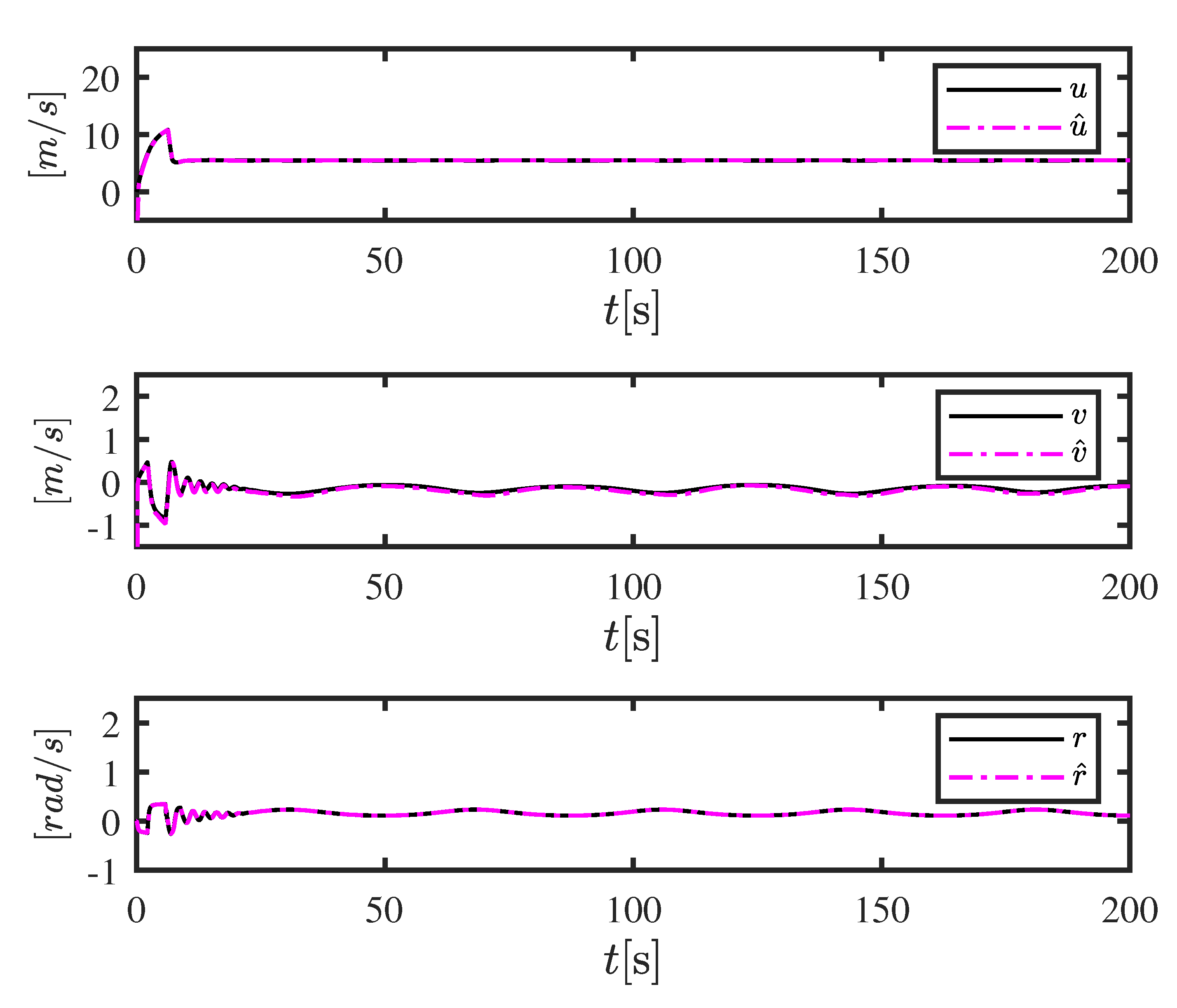
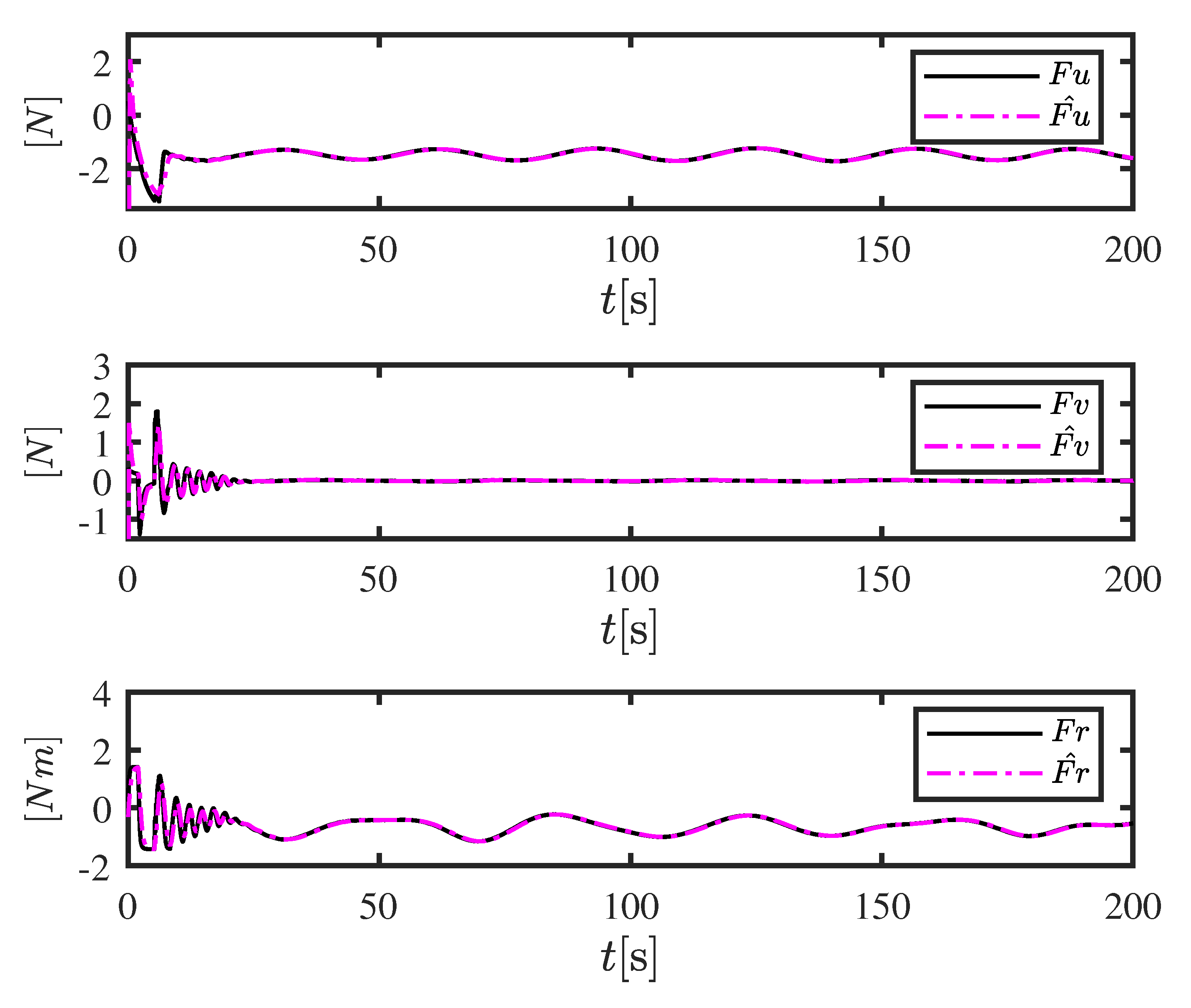
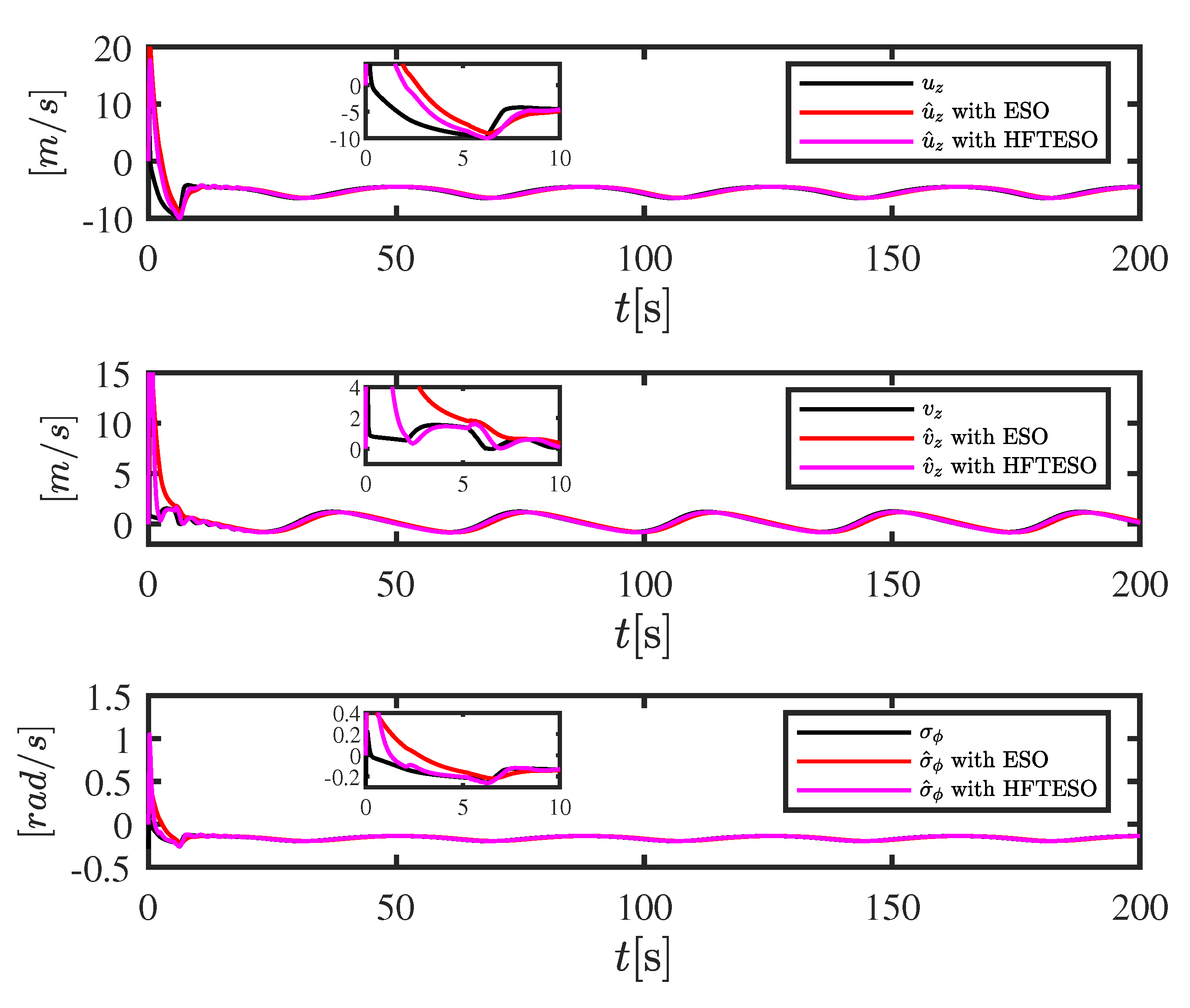
Figure 6, Figure 7 and Figure 8 illustrate the estimation performance of the proposed observer framework, which includes a velocity observer, a lumped disturbance observer, and a high-dimensional fixed-time extended state observer (HFTESO). Figure 6 compares the estimated and actual velocities of the follower USV, showing that the designed velocity observer can accurately reconstruct the unknown velocity states. Figure 7 presents the estimation results of lumped disturbances, indicating that the disturbance observer is effective in capturing the external unknown disturbances acting on the follower. Figure 8 shows the estimation results of unknown states under the same system conditions using two different observers. The results demonstrate that the proposed HFTESO achieves significantly faster estimation compared to the alternative method.
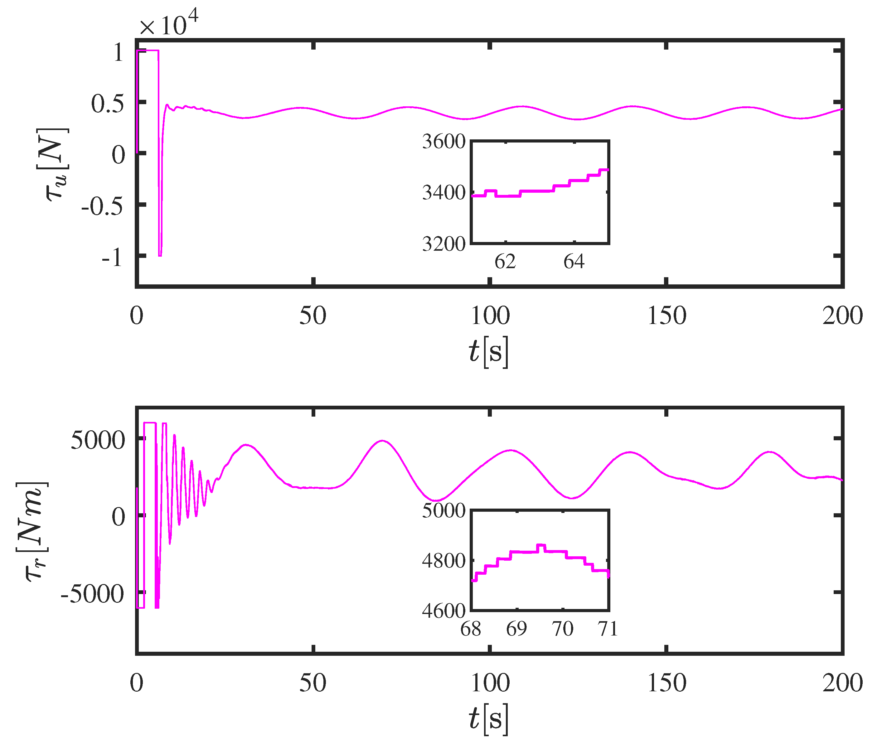
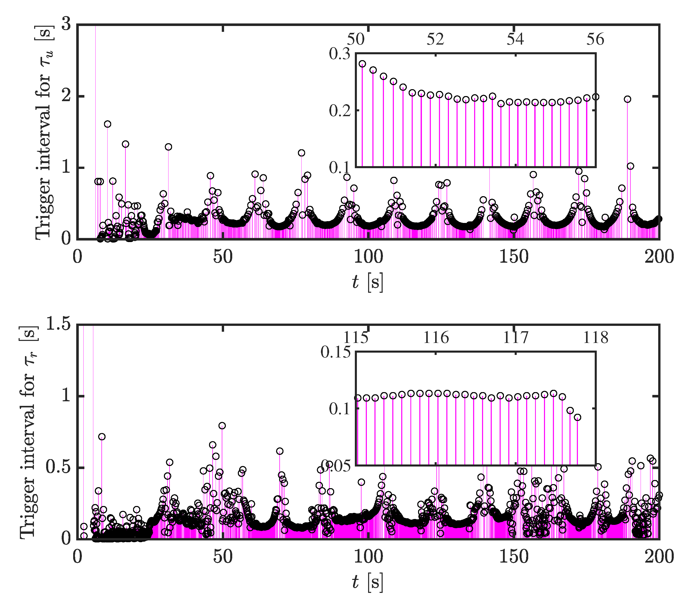
The effectiveness of the proposed fixed-threshold event-triggered controller is validated through Figure 9 and Figure 10 and Table 3. Figure 9 shows the control inputs τ u and τ r generated by the controller. Their stable ranges are consistent with the actual operational constraints of the ‘LanXin’ USV, confirming the practical feasibility of the proposed control strategy. Figure 10 illustrates the triggering instants and the corresponding inter-event intervals, providing insight into the temporal behavior of the event-triggering mechanism. Furthermore, Table 3 compares the total number of triggering events under the time-triggered and fixed-threshold strategies. It is evident that the fixed-threshold event-triggered approach significantly reduces the triggering frequency, thereby alleviating actuator wear and improving overall control efficiency.
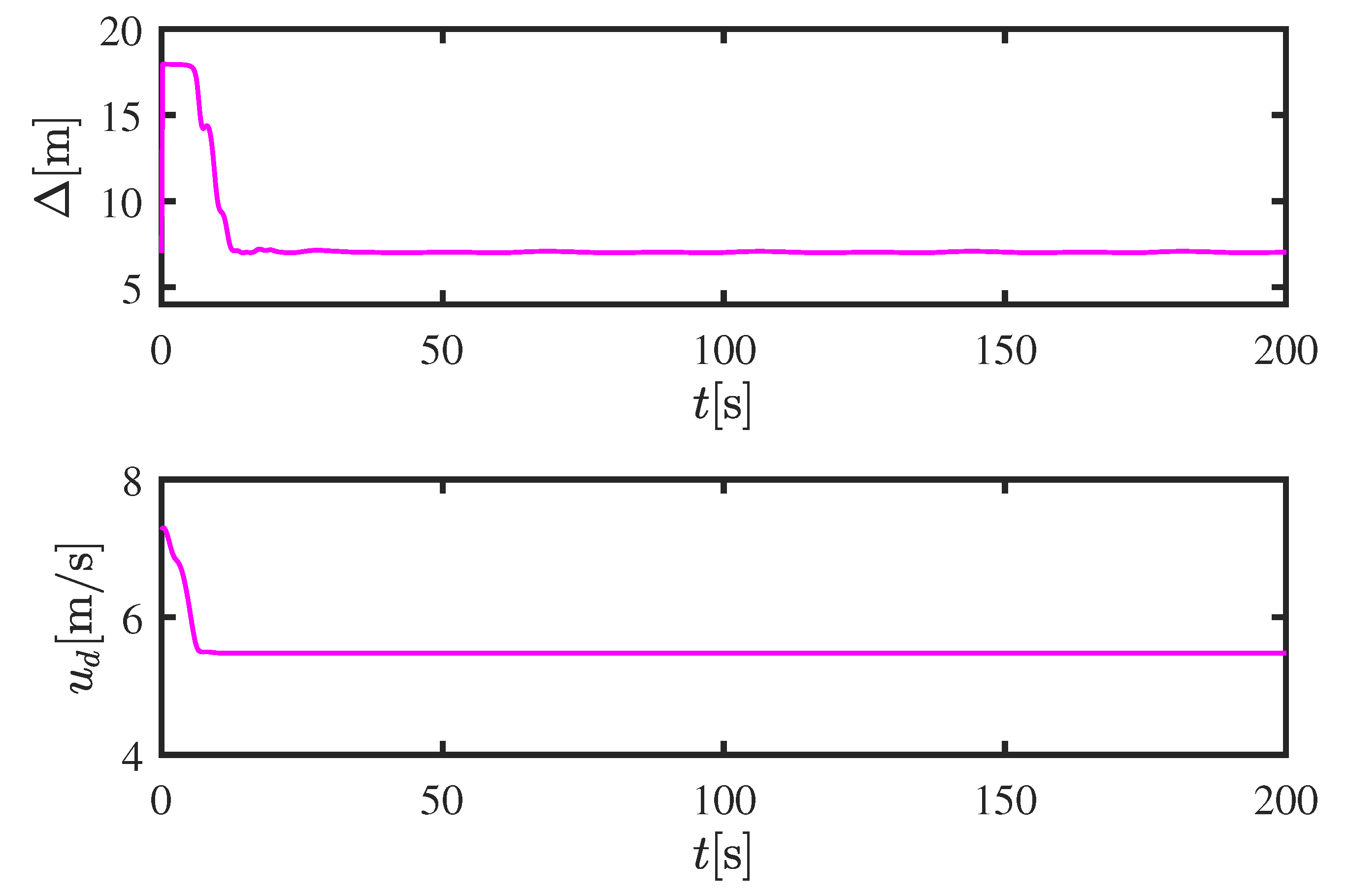
Figure 11 illustrates the variation of the look-ahead distance and the surge velocity of the follower. As shown in the figure, the designed adaptive look-ahead distance and adaptive surge velocity exhibit effective performance, validating the effectiveness of the proposed design.

6. Limitations and Practical Deployment Challenges

Although the proposed fixed-time target-enclosing control framework demonstrates strong theoretical guarantees and satisfactory simulation performance, several limitations should be acknowledged before practical deployment. First, the current study relies on an idealized 3-DOF kinematic model, which neglects complex hydrodynamic effects such as wave-induced forces, varying water currents, and nonlinear viscous damping. These factors may influence the accuracy of state estimation and control precision in real-world maritime environments. Second, the simulation environment (SimuNPS) simplifies sensor and actuator dynamics, including time delays, quantization errors, and power constraints. Such simplifications can lead to discrepancies between simulated and real-world behaviors. Third, while the proposed observers and controllers are designed to ensure fixed-time convergence, their parameter tuning may still require adaptation when implemented on physical platforms due to hardware limitations and environmental uncertainties. In future work, we plan to integrate the proposed framework into a hardware-in-the-loop (HIL) setup and validate its performance on an experimental USV platform. Additionally, the incorporation of adaptive learning-based components and disturbance estimation under stochastic ocean conditions will be explored to enhance real-world applicability and robustness.

7. Real-World Implementation and Expectations

The proposed control framework is designed with practical implementation in mind. In real-world applications, the algorithm can be embedded into an onboard control system that integrates real-time sensor feedback, communication modules, and propulsion control units. The fixed-time observer and event-triggered control structure are computationally efficient, making them suitable for low-latency embedded processors commonly used in USV systems. In the initial stage, the framework will be validated through hardware-in-the-loop (HIL) experiments to evaluate performance under realistic sensor and actuator conditions. Following this, implementation on an experimental unmanned surface vehicle will be carried out to assess its robustness in actual sea environments. It is expected that the proposed approach will significantly enhance the reliability, response speed, and autonomy of future USV operations.

8. Conclusions

In this paper, a novel global fixed-time target enclosing tracking control strategy has been proposed for unmanned surface vehicles (USVs). The proposed method guarantees that all closed-loop system errors converge to arbitrarily small neighborhoods of the origin within a fixed time, while ensuring that all system states remain bounded. To this end, a Fixed-Time Target Enclosing Line-of-Sight (FTTELOS) guidance law was developed to generate the desired heading angular velocity and surge velocity. Compared with the traditional TELOS method, FTTELOS offers greater flexibility and significantly accelerates the convergence of the enclosing distance and angle errors. Moreover, a High-order Fixed-Time Extended State Observer (HFTESO) was introduced to estimate unknown state variables in the system. Compared to the conventional ESO, the HFTESO provides faster and more accurate estimation performance. Finally, a control scheme combining fixed-time sliding mode control with a fixed-threshold event-triggered mechanism was designed to improve robustness while reducing control update frequency. This integrated strategy achieves fast fixed-time convergence of system state errors under lumped uncertainties and input saturation, while significantly reducing the number of controller activations, thereby relieving the burden on actuators and improving overall efficiency.
Future Work. In future research, we plan to extend the proposed control framework in several directions. First, hardware-in-the-loop (HIL) experiments and real-world sea trials will be conducted to further verify the framework’s feasibility and robustness under complex marine conditions. Second, adaptive and learning-based elements will be incorporated into the fixed-time observer and controller to improve performance in the presence of parameter uncertainties and stochastic disturbances. Third, communication constraints and cooperative behaviors among multiple USVs will be investigated to develop distributed fixed-time target-enclosing control strategies. These efforts will further enhance the practicality and scalability of the proposed approach for autonomous marine operations.

Author Contributions

G.M.: writing the manuscript, carrying out experiments, data analyzing; X.H., Y.F., D.M. and F.S.: conceptualization, methodology, supervision, data processing, editing figures; L.S. and H.L. provide the simulation software SimuNPS. All authors reviewed the manuscript. All authors have read and agreed to the published version of the manuscript.

Funding

This work was supported by National Key Research and Development Program of China (Grant number 2022YFB4301401), National Natural Science Foundation of China (Grant number 52301360, 61976033), Pilot Base Construction and Pilot Verification Plan Program of Liaoning Province of China (Grant number 2022JH24/10200029), China Transportation Education Research Association 2024-2026 Educational Science Research (Grant number JT2024YB097), Dalian Key Science and Technology Research and Development Plan (Grant number 2023YF11GX007), Program of Graduate Education and Teaching Reform (Grant number LNYJG2024142, YJG2024707), the Key Program for Basic Research of China (Grant number JCKY2023206B026). Dalian City Science and Technology Plan (Key) Project (Grant number 2024JB11PT007).

Data Availability Statement

The original contributions presented in this study are included in the article. Further inquiries can be directed to the corresponding author.

Conflicts of Interest

Author Feng Sun was employed by COSCO Shipping Heavy Industry (Dalian) Co., Ltd. Authors Hongbiao Li and Linlong Shi were employed by Shanghai KeLiang Information Technology Co., Ltd. The remaining authors declare that the research was conducted in the absence of any commercial or financial relationships that could be construed as a potential conflict of interest.

References

  1. Fan, Y.; Shi, Y.; Mu, D.; Liu, J.; Li, Z. Global fixed-time adaptive fuzzy path following control for unmanned surface vehicles subject to lumped uncertainties and actuator saturation. Ocean Eng. 2023, 286, 115533. [Google Scholar] [CrossRef]
  2. Peng, Z.; Wang, D.; Wang, W.; Liu, L. Containment control of networked autonomous underwater vehicles: A predictor-based neural DSC design. ISA Trans. 2015, 59, 160–171. [Google Scholar] [CrossRef]
  3. Zhang, G.; Zhang, X.; Zheng, Y. Adaptive neural path-following control for underactuated ships in fields of marine practice. Ocean Eng. 2015, 104, 558–567. [Google Scholar] [CrossRef]
  4. Shen, C.; Shi, Y.; Buckham, B. Integrated path planning and tracking control of an AUV: A unified receding horizon optimization approach. IEEE/ASME Trans. Mechatron. 2016, 22, 1163–1173. [Google Scholar] [CrossRef]
  5. Xiang, X.; Yu, C.; Zhang, Q. Robust fuzzy 3D path following for autonomous underwater vehicle subject to uncertainties. Comput. Oper. Res. 2017, 84, 165–177. [Google Scholar] [CrossRef]
  6. Cui, R.; Yang, C.; Li, Y.; Sharma, S. Adaptive neural network control of AUVs with control input nonlinearities using reinforcement learning. IEEE Trans. Syst. Man Cybern. Syst. 2017, 47, 1019–1029. [Google Scholar] [CrossRef]
  7. Shen, C.; Shi, Y.; Buckham, B. Trajectory tracking control of an autonomous underwater vehicle using Lyapunov-based model predictive control. IEEE Trans. Ind. Electron. 2017, 65, 5796–5805. [Google Scholar] [CrossRef]
  8. Yue, Y.; Ning, J.; Hu, X.; Li, W. Event-triggered anti-disturbance trajectory tracking for under-actuated surface vehicle under multiple constraints and input quantization. Ocean Eng. 2025, 329, 121111. [Google Scholar] [CrossRef]
  9. Liu, L.; Wang, D.; Peng, Z.; Chen, C.P.; Li, T. Bounded neural network control for target tracking of underactuated autonomous surface vehicles in the presence of uncertain target dynamics. IEEE Trans. Neural Netw. Learn. Syst. 2018, 30, 1241–1249. [Google Scholar] [CrossRef]
  10. Fan, Y.; Qiao, S.; Wang, G.; Chen, S.; Zhang, H. A modified adaptive Kalman filtering method for maneuvering target tracking of unmanned surface vehicles. Ocean Eng. 2022, 266, 112890. [Google Scholar] [CrossRef]
  11. Marshall, J.A.; Broucke, M.E.; Francis, B.A. Pursuit formations of unicycles. Automatica 2006, 42, 3–12. [Google Scholar] [CrossRef]
  12. Lan, Y.; Yan, G.; Lin, Z. Distributed control of cooperative target enclosing based on reachability and invariance analysis. Syst. Control Lett. 2010, 59, 381–389. [Google Scholar] [CrossRef]
  13. Zheng, R.; Liu, Y.; Sun, D. Enclosing a target by nonholonomic mobile robots with bearing-only measurements. Automatica 2015, 53, 400–407. [Google Scholar] [CrossRef]
  14. Shames, I.; Dasgupta, S.; Fidan, B.; Anderson, B.D. Circumnavigation using distance measurements under slow drift. IEEE Trans. Autom. Control 2011, 57, 889–903. [Google Scholar] [CrossRef]
  15. Ma, L.; Cao, C.; Hovakimyan, N.; Dobrokhodov, V.; Kaminer, I. Adaptive vision-based guidance law with guaranteed performance bounds. J. Guid. Control Dyn. 2010, 33, 834–852. [Google Scholar] [CrossRef]
  16. Ghommam, J.; Fethalla, N.; Saad, M. Quadrotor circumnavigation of an unknown moving target using camera vision-based measurements. IET Control Theory Appl. 2016, 10, 1874–1887. [Google Scholar] [CrossRef]
  17. Yu, X.; Liu, L.; Feng, G. Distributed circular formation control of nonholonomic vehicles without direct distance measurements. IEEE Trans. Autom. Control 2018, 63, 2730–2737. [Google Scholar] [CrossRef]
  18. Xiang, X.; Lapierre, L.; Jouvencel, B. Smooth transition of AUV motion control: From fully-actuated to under-actuated configuration. Robot. Auton. Syst. 2015, 67, 14–22. [Google Scholar] [CrossRef]
  19. Lekkas, A.M.; Fossen, T.I. Integral LOS path following for curved paths based on a monotone cubic Hermite spline parametrization. IEEE Trans. Control Syst. Technol. 2014, 22, 2287–2301. [Google Scholar] [CrossRef]
  20. Liu, L.; Wang, D.; Peng, Z. ESO-based line-of-sight guidance law for path following of underactuated marine surface vehicles with exact sideslip compensation. IEEE J. Ocean. Eng. 2016, 42, 477–487. [Google Scholar] [CrossRef]
  21. Jiang, Y.; Peng, Z.; Wang, D.; Chen, C.P. Line-of-sight target enclosing of an underactuated autonomous surface vehicle with experiment results. IEEE Trans. Ind. Inform. 2019, 16, 832–841. [Google Scholar] [CrossRef]
  22. Wang, N.; Lv, S.; Zhang, W.; Liu, Z.; Er, M.J. Finite-time observer based accurate tracking control of a marine vehicle with complex unknowns. Ocean Eng. 2017, 145, 406–415. [Google Scholar] [CrossRef]
  23. Zhang, J.; Yu, S.; Yan, Y. Fixed-time output feedback trajectory tracking control of marine surface vessels subject to unknown external disturbances and uncertainties. ISA Trans. 2019, 93, 145–155. [Google Scholar] [CrossRef] [PubMed]
  24. Sun, W.; Gao, X.; Yu, Y. Dual Deep Neural Networks for Improving Trajectory Tracking Control of Unmanned Surface Vehicle. In Proceedings of the 2020 Chinese Automation Congress (CAC), Shanghai, China, 6–8 November 2020; pp. 3441–3446. [Google Scholar]
  25. Majidiyan, H.; Enshaei, H.; Howe, D. A Concise Account for Challenges of Machine Learning in Seakeeping. Procedia Comput. Sci. 2025, 253, 2849–2858. [Google Scholar] [CrossRef]
  26. Yu, Y.; Guo, C.; Yu, H. Finite-time PLOS-based integral sliding-mode adaptive neural path following for unmanned surface vessels with unknown dynamics and disturbances. IEEE Trans. Autom. Sci. Eng. 2019, 16, 1500–1511. [Google Scholar] [CrossRef]
  27. Sun, Z.; Zhang, G.; Yi, B.; Zhang, W. Practical proportional integral sliding mode control for underactuated surface ships in the fields of marine practice. Ocean Eng. 2017, 142, 217–223. [Google Scholar] [CrossRef]
  28. Li, T.; Zhao, R.; Chen, C.P.; Fang, L.; Liu, C. Finite-time formation control of under-actuated ships using nonlinear sliding mode control. IEEE Trans. Cybern. 2018, 48, 3243–3253. [Google Scholar] [CrossRef]
  29. Ashrafiuon, H.; Muske, K.R.; McNinch, L.C.; Soltan, R.A. Sliding-mode tracking control of surface vessels. IEEE Trans. Ind. Electron. 2008, 55, 4004–4012. [Google Scholar] [CrossRef]
  30. Yu, R.; Zhu, Q.; Xia, G.; Liu, Z. Sliding mode tracking control of an underactuated surface vessel. IET Control Theory Appl. 2012, 6, 461–466. [Google Scholar] [CrossRef]
  31. Qiao, L.; Zhang, W. Adaptive non-singular integral terminal sliding mode tracking control for autonomous underwater vehicles. IET Control Theory Appl. 2017, 11, 1293–1306. [Google Scholar] [CrossRef]
  32. Ding, L.; Han, Q.L.; Ge, X.; Zhang, X.M. An overview of recent advances in event-triggered consensus of multiagent systems. IEEE Trans. Cybern. 2017, 48, 1110–1123. [Google Scholar] [CrossRef]
  33. Mazo Jr, M.; Anta, A.; Tabuada, P. An ISS self-triggered implementation of linear controllers. Automatica 2010, 46, 1310–1314. [Google Scholar] [CrossRef]
  34. Xing, L.; Wen, C.; Liu, Z.; Su, H.; Cai, J. Event-triggered adaptive control for a class of uncertain nonlinear systems. IEEE Trans. Autom. Control 2016, 62, 2071–2076. [Google Scholar] [CrossRef]
  35. Ge, X.; Han, Q.L.; Zhang, X.M. Achieving cluster formation of multi-agent systems under aperiodic sampling and communication delays. IEEE Trans. Ind. Electron. 2017, 65, 3417–3426. [Google Scholar] [CrossRef]
  36. Postoyan, R.; Bragagnolo, M.C.; Galbrun, E.; Daafouz, J.; Nešić, D.; Castelan, E.B. Event-triggered tracking control of unicycle mobile robots. Automatica 2015, 52, 302–308. [Google Scholar] [CrossRef]
  37. Jain, R.P.; Aguiar, A.P.; de Sousa, J.B. Cooperative path following of robotic vehicles using an event-based control and communication strategy. IEEE Robot. Autom. Lett. 2018, 3, 1941–1948. [Google Scholar] [CrossRef]
  38. Ge, X.; Han, Q.L. Distributed formation control of networked multi-agent systems using a dynamic event-triggered communication mechanism. IEEE Trans. Ind. Electron. 2017, 64, 8118–8127. [Google Scholar] [CrossRef]
  39. Polyakov, A. Nonlinear feedback design for fixed-time stabilization of linear control systems. IEEE Trans. Autom. Control 2011, 57, 2106–2110. [Google Scholar] [CrossRef]
  40. Chen, M.; Wang, H.; Liu, X. Adaptive fuzzy practical fixed-time tracking control of nonlinear systems. IEEE Trans. Fuzzy Syst. 2019, 29, 664–673. [Google Scholar] [CrossRef]
  41. Wang, S.; Sun, M.; Xu, Y.; Liu, J.; Sun, C. Predictor-based fixed-time LOS path following control of underactuated USV with unknown disturbances. IEEE Trans. Intell. Veh. 2023, 8, 2088–2096. [Google Scholar] [CrossRef]
  42. Zuo, Z.; Tian, B.; Defoort, M.; Ding, Z. Fixed-time consensus tracking for multiagent systems with high-order integrator dynamics. IEEE Trans. Autom. Control 2017, 63, 563–570. [Google Scholar] [CrossRef]
  43. Fan, Y.; Qiu, B.; Liu, L.; Yang, Y. Global fixed-time trajectory tracking control of underactuated USV based on fixed-time extended state observer. ISA Trans. 2023, 132, 267–277. [Google Scholar] [CrossRef] [PubMed]
Figure 1. Diagram of target enclosing control.
Jmse 13 02094 g001
Figure 2. Geometric sketch of USV target enclosing under LOS.
Jmse 13 02094 g002
Figure 3. ’LanXin’ USV.
Jmse 13 02094 g003
Figure 4. Target enclosing tracking control performance results.
Jmse 13 02094 g004
Figure 5. δ e and ϕ e .
Jmse 13 02094 g005
Figure 6. u, v and r of ‘LanXin’ USV.
Jmse 13 02094 g006
Figure 7. Lumped disturbance F u , F v and F r .
Jmse 13 02094 g007
Figure 8. Unknown state u z , v z and σ ϕ .
Jmse 13 02094 g008
Figure 9. Control input τ u and τ r .
Jmse 13 02094 g009
Figure 10. Triggering interval of the controller.
Jmse 13 02094 g010
Figure 11. Δ and u d .
Jmse 13 02094 g011
Table 1. Target enclosing tracking system parameters.
ParametersValueParametersValue
μ 1 (1, 1, 1) λ 1 0.45
μ 2 (5, 15, 6) λ 2 0.6
μ 3 (5, 5, 6) λ 3 2
μ 4 (5, 18, 6) λ 4 1
α v 6/7m6/7
β v 7/6n7/6
σ 1 (0.1, 0.1, 0.1) k r 1
σ 2 (0.01, 0.01, 0.01) k u 1 1
σ 3 (0.01, 0.01, 0.01) k u 2 0.1
σ 4 (3, 3, 3) u d m i n 30
α f 5/6 Δ min 7
β f 6/5 Δ max 18
k i ( 1 ,   2 ,   3 ,   4 ) (10, 10, 9, 1)c1
k i ( 5 ,   6 ,   7 ,   8 ) (3, 6, 9, 9)h2
k i ( 9 ,   10 ,   11 ,   12 ) (3, 10, 9, 9) λ u 1 1.4
α ,   γ 0.7 λ u 2 1
β ,   δ 1.2 λ r 1 0.3
k z i ( 1 ,   2 ,   3 ,   4 ) 0.1 λ r 2 0.2
ϕ i ( 1 ,   2 ) 0.01 a s 7/6
p 1 5/6 b s 6/7
p 2 2/3 n 1 5/4
q 1 6/5 α u 1 2.6
q 2 31/30 α u 2 0.46
ω 1 0.96 α r 1 0.6
ω 2 0.43 α r 2 0.4
ω 3 1.3 κ i ( u ,   r ) 1
b u 1 l i ( u ,   r ) 1
b r 1 μ i ( u ,   r ) 3
Φ a 0.01 m u 20
Φ b 0.02 m r 25
Table 2. Convergence time T c of δ e and ϕ e under TELOS and FTTELOS.
Method T c of δ e (s) T c of ϕ e (s)
TELOS13.6410.46
FTTELOS10.227.52
Table 3. Number of triggering events of the follower under different triggering strategies.
Method τ u τ r
Time triggered20,00020,000
Fixed threshold triggered12593344
Disclaimer/Publisher’s Note: The statements, opinions and data contained in all publications are solely those of the individual author(s) and contributor(s) and not of MDPI and/or the editor(s). MDPI and/or the editor(s) disclaim responsibility for any injury to people or property resulting from any ideas, methods, instructions or products referred to in the content.