Article

Development of New Jack-Up Substructure Supporting Offshore Wind Turbines in Multi-Layered Soils: Geotechnical Aspects

Department of Civil and Environmental Engineering, Kongju National University, 1223-24 Cheonan-daero, Seobuk-gu, Cheonan-si 31080, Republic of Korea
*
Author to whom correspondence should be addressed.
J. Mar. Sci. Eng. 2025, 13(11), 2060; https://doi.org/10.3390/jmse13112060
Submission received: 11 August 2025 / Revised: 15 September 2025 / Accepted: 17 October 2025 / Published: 28 October 2025
(This article belongs to the Special Issue Marine Geotechnical Applications in Marine Structures)

Abstract

Few studies have addressed jack-up substructures with spudcans for offshore wind turbines targeting multi-layer seabed conditions, which are frequently found in the Korean seabed. This study analyzed existing guidelines to establish geotechnical design procedures for a newly proposed jack-up substructure supported by tubular legs with spudcans, as well as to present design cases for a target site. This jack-up spudcan was designed for seabed conditions representative of the Korean southwestern offshore seabed, consisting of a sand–clay–sand layer. Analytical procedures from ISO and InSafeJIP guidelines were adopted to estimate the vertical bearing capacity of the spudcan. The yield envelope was determined based on this estimation, and the spudcan size was selected using structural reaction forces. Predictions from theoretical equations were compared with results from centrifuge tests for verification and discussion. Theoretical vertical capacities according to ISO match well with centrifuge results in sand-over-clay layers, while InSafeJIP shows a similar trend in intermediate clay layers. For clay-over-sand layers, only the vertical capacity formula for a single-sand layer case is available in the guidelines, which tends to overestimate the actual capacity for the underlying sand. However, by applying appropriately selected strength reduction factors, the actual foundation behavior can be reasonably predicted for design, but it is still overestimated, requiring further study.

1. Introduction

In previous decades, offshore wind turbines (OWTs) have become progressively larger with the growing demand for larger generation capacity, so the supporting substructures must also be scaled up. Due to budget constraints, new economic types of substructures and construction methods are under development and proposal.
Currently, proven types of fixed substructures for OWTs, including monopiles, gravity-based foundations, piled jackets, and jackets with suction buckets, have been investigated through experimental and numerical studies for Korean offshore soils [1,2,3,4]. The selection of an appropriate foundation type depends on site-specific seabed conditions and requires evaluating the load-bearing capacity of the substructure and the cost-effectiveness of its installation, considering environmental loads, soil stratigraphy, and particularly complex soil strength profiles.
The construction of fixed offshore wind foundations typically demands specialized wind turbine installation vessels (WTIVs), which facilitate the transportation, installation, and maintenance of OWTs and their substructures. However, such vessels have limited availability in certain regions, often resulting in substantial financial burdens and prolonged installation schedules, particularly in the Korean offshore area. To address these challenges, this study investigates a proposed novel jack-up substructure for OWTs [5,6], which has the potential to overcome the limitations of conventional fixed foundations and their reliance on WTIVs.
The assembly and installation of turbines, blades, towers, and substructures, which were traditionally carried out offshore, are instead performed onshore in a single operation, and the components are transported to the installation site using conventional harbor tugs, without the need for a WTIV. At the site, the foundation is installed into the seabed using a jacking system without drilling or driving. This jack-up capability allows easy relocation and reinstallation, enabling position adjustments in response to changing environmental conditions. Furthermore, since the foundation is not installed using grout or similar permanent methods, it can also be removed by jacking it up from the seabed.
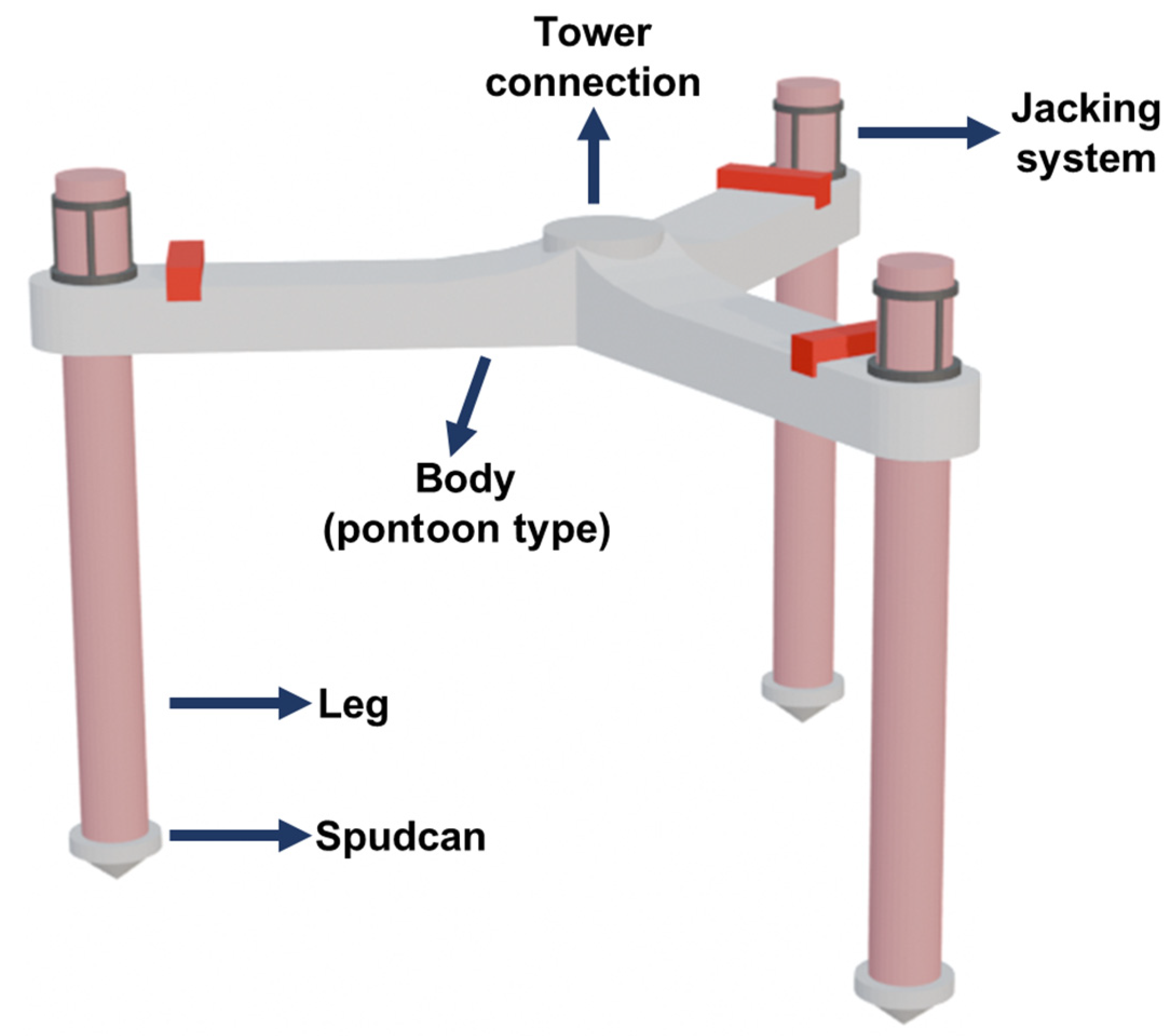
The jack-up substructure for offshore wind turbines is one of the substructures for offshore wind generators utilized by the U.S. Bureau of Ocean Energy Management (BOEM). These turbines are mounted on platforms, adopting a similar concept to a mobile jack-up unit, which can respond to various seabed surfaces, including complex soil conditions. The platform is supported by three or more legs equipped with spudcans that penetrate the seabed and secure the leg–spudcan system in the soil [7,8,9]. The jack-up type has a jacking system, improving the mobility of the jack-up substructure. The procedure for installing a jack-up foundation for OWTs is as follows: (i) The OWT platform, consisting of a pontoon, superstructure (comprising the tower and rotor nacelle), and foundation, is towed to the wind farm site by tugboats. (ii) When the wind turbine generator mounted on a jack-up substructure arrives at the site, preloading is performed to install the leg–spudcan system into the seabed. During the preloading stage, the self-weight of the jack-up substructure is increased by ballasting the pontoon with seawater, and then the leg is jacked into the soil to an appropriately designed depth for stabilization.
Recent research in Korean coastal regions has been continuously advancing. Kim et al. [10] analyzed five types of offshore wind turbine foundations and proposed methods for developing and applying suitable foundation types. Ali et al. [11] investigated the optimal layout of wind turbines with monopile foundations based on wind speed data from the Wido region of South Korea. Research on jacket substructures has also been conducted by Tran and Lee [12], focusing on the influence of jacket geometry and bracing systems on dynamic performance. Regarding spudcan foundations, Park et al. [13] proposed a procedure to evaluate the structural integrity of foundation systems for offshore wind turbine installation vessels, while Falcon et al. [14] examined the interaction mechanisms between spudcans and adjacent piles through centrifuge modeling. However, studies specifically addressed leg-type pile foundations and the determination of spudcan dimensions, so the results of these studies remain limited for the development of the substructure. Previous research has numerically and experimentally analyzed the penetration behavior of spudcan foundations in the Korean offshore seabed including silty sand and clays [6,9]. Lee et al. [6] analyzed the influence of soil conditions on the penetration behavior of spudcans through centrifuge model testing. Choo et al. [1], Kim et al. [3], and Baek et al. [15] tackled the geological challenges associated with multi-layered soils in the Korean seabed utilizing tripod bucket foundations and rock-socketed monopiles.
This study reviews the geotechnical design process of the new jack-up substructure for an offshore wind turbine installed on multi-layered soils through the International Organization for Standardization (ISO 19905-1:2023) [16], Guidelines for Site Specific Assessment of Mobile Jack-up units (SNAME) [17], and Improved Guidelines for the Prediction of Geotechnical Performance of Spudcan Foundations during Installation and Removal of Jack-up Units (InSafeJIP report) [18]. Moreover, the design check of leg–spudcan vertical resistance is verified with centrifuge model tests. The lateral loads are compared with failure envelopes of the spudcan to check the stability of the jack-up substructure against environmental loads for offshore wind turbines.
This study aims to examine existing guidelines for the multi-layered case. After the dimensions of the jack-up superstructure are determined, the specifications of an appropriate foundation structure must be selected to provide adequate supporting capacity. Accordingly, Section 2 reviews the theoretical approaches proposed by ISO [16] and InSafeJIP [18] for the design of jack-up spudcan foundations to check the applicability to the multi-layered seabed. Since the vertical bearing capacity of the spudcan is the most critical factor, both theories are utilized to assess the adequacy of the design, as described in Section 2.1. The failure envelope of the spudcan, which can be derived based on its vertical bearing capacity, is calculated using the ISO methodology, and the procedure adopted in this study is detailed in Section 2.2. Thus, the bearing capacity calculated from the theoretical formulation introduced in Section 2 is discussed in Section 3 with an example to determine the spudcan size and penetration depth that can provide stable support under the maximum available preload of the example prototype jack-up structure.

2. Theory

2.1. Vertical Bearing Capacity of Jack-Up Spudcan

2.1.1. ISO 19905-1:2023 [16] Method

There are suggestions for the bearing capacity of the jack-up foundation by the International Organization for Standardization (ISO 19905-1:2023) [16]. Three different foundation failure mechanisms are considered when predicting spudcan penetration in layered soils: general shear, squeezing, and punch-through. In the first mechanism, the soil strengths of subsequent layers are not significantly affected, and the bearing capacity can be calculated by considering that the spudcan is located in uniform soil. The second mechanism occurs when the upper layer is soft clay and the layer underneath is a hard stratum. On the other hand, the latter mechanism occurs when a spudcan penetrates a sand-over-clay or stiff-clay-over-soft-clay layer, which can be potentially dangerous during installation and can result in rapid leg penetration.
  • Squeezing of clay
Squeezing occurs when a significantly stronger layer is located under soft clay; it refers to a phenomenon in which the vertical bearing capacity increases due to the large bearing capacity of the lower hard layer at the upper soft clay layer adjacent to the hard soil. The gross ultimate vertical bearing capacity (Qv) [kN] of the spudcan in soft clay overlying hard soil can be calculated using Equation (1) [19,20], as shown in Figure 1a. The upper bound capacity in Equation (1) (for the case of the thickness of the weaker clay layer beneath the spudcan T [m] << spudcan diameter B [m]) is determined by the ultimate bearing capacity of the underlying strong soil layer. The lower bound capacity in Equation (1) is given by the general failure in the clay layer, which is the ultimate bearing capacity formula of uniform clay, and squeezing occurs at B ≥ 3.45T(1 + 1.025z/B) for z/B ≤ 2.5.
Q v = A a s + b s B T + 1.2 z B s u + p 0 A N c s c d c s u + p 0
where dc = 1 + 0.2z/B and the squeezing factor constants are as = 5.00 and bs = 0.33, which is referred from Brown and Meyerhof [19]. The value of Nc·sc should be taken as 6.0 following [21,22], where Nc, sc, and dc are bearing capacity factors. z [m] is the depth of foundation penetration, A [m2] is the spudcan bearing area, su [kPa] is the undrained shear strength of clay, and p′0 [kN/m2] is the effective overburden pressure at depth.
2.
Punch-through (sand overlying clay)
The bearing capacity of the spudcan on the sand-over-clay layer is calculated by considering the fictitious footing at the interface between the sand and clay layers by the load spread model, as shown in Figure 1b. The footing has an equivalent diameter (B′) by the soil plug under the footing bottom, and the weight of this soil plug (W) is considered. Thus, the vertical bearing capacity is calculated by subtracting the weight of the soil plug (W) from the ultimate bearing capacity of uniform clay (Qu,b) [kN], as shown in Equations (2)–(4). Qu,b in Equation (3) is the ultimate vertical foundation bearing capacity for the fictitious footing at the interface between the sand and clay layers with no backfill.
Q v = Q u , b W
Q u , b = A N c s c d c s u + p 0
W = 0.25 π B 2 H γ
where the equivalent diameter (B′) [m] is calculated as B + 2H/ns in Equation (4), and the applied load spread factor of ns is 3.0, as recommended by [23]. γ′ [kN/m3] is the effective unit weight. H is the distance from the spudcan maximum bearing area to the weaker layer below, as shown in Figure 1b. The vertical bearing capacity of the spudcan in single sand can be obtained using
Q v = A s u N c s c d c + p 0
where a dγ of 1.0 is applied as the depth factor on surcharge for drained soils; dq can be calculated by 1 + 2tanØ′(1 + sinØ′arctan(z/B) as the depth factor for drained soils; and Nγ and Nq are the bearing capacity factors [24].
Field observations indicate that measured footing penetrations were substantially greater than those predicted using friction angles (ϕ) [°] derived from Vesic’s and Brinch Hansen’s bearing capacity formulations [23,25]. Consistent with the findings of Graham [26], James [27], and Kimura [28], this discrepancy is attributed to scale effects, for which the adoption of reduced friction angles has been recommended. Accordingly, it is proposed that friction angles obtained from laboratory tri-axial tests be reduced by 5° when estimating penetration capacity in silica sands.

2.1.2. InSafeJIP [18] Method for Two-Layered System

It has been confirmed that the ISO method shows a large difference in predicting bearing capacity when calculating the capacity of the interface in multi-layered soils [6,29]. Thus, to complement this problem, the method in [18] is additionally utilized in this study. The InSafeJIP (Improved guidelines for the prediction of geotechnical performance of spudcan foundations during installation and removal of jack-up units) project, introduced by [18], was completed in response to the limitations of design methods for spudcan foundations used in jack-up offshore structures. It aimed to provide refined guidelines for evaluating the geotechnical performance of spudcans during both the installation and removal phases. In particular, the detailed depth-specific formula is provided for the punch-through and squeezing mechanisms passing through heterogeneous layer interfaces.
  • Soft over strong soils
When the lower stratum is considerably strong in Figure 2a, deformations are fully confined within the upper layer, with the soft soil predominantly displaced sideways due to the squeezing mechanism.
Q v = A N c + B n h l a y e r h 1 s u t o p + γ c l a y , t o p ( h A + V C V s o i l )
where A [m2] is the widest spudcan bearing area; B [m] is the spudcan diameter; n is the squeezing factor; hlayer [m] is the thickness from the ground surface to the shoulder top of the spudcan; h [m] is the spudcan penetration depth measured from the lowest depth of the maximum plan area; sutop [kPa] is the undrained shear strength of the upper clay; γ′clay,top [kN/m3] is the effective unit weight of the upper clay; VC [m3] is the volume of the spudcan full base; and Vsoil [m3] is the volume of the backfill sand above the spudcan shoulder.
Since the bearing capacity equation was not provided for the case of penetration through an overlying clay layer into an underlying sand layer, the capacity was estimated using the single-sand-condition formula:
Q v = A γ 0.5 B N γ ζ h γ + h N q ζ s q ζ h q + γ ( V C V s o i l )
where γ′ [kN/m3] is the effective unit weight of soils.
For bearing capacity, shape and depth factors ( N γ ,   N q ,   ζ h γ ,   ζ s q ,   ζ h q ) should be used, as recommended by [20]. In the bearing capacity analysis for sand, an additional stage is required to account for the mobilization factor (Fmob), which modifies the bearing capacity factors based on the degree of mobilized resistance. While this approach can be extended to clay, it is generally omitted due to its relatively minor influence on the bearing capacity in clay and the increased complexity it introduces. The reduction factor (Fmob) was recommended to be between 0.25 and 0.5, where the lower values of Fmob are generally applicable to more compressible materials, while higher values may be used for stiffer soils by the report database from the North Sea, Gulf of Mexico, and offshore Australia.
2.
Strong over soft soils (sand-over-clay)
For loose to medium dense sand (25° < ϕ′ < 35°) overlying the soft soils, the vertical bearing capacity of the spudcan can be calculated using Equation (8) considering soil backflow and spudcan buoyancy when the spudcan is penetrating the upper layer (h < hlayer). K s tan ϕ can be replaced with 2.5 s u γ s a n d × B 0.6 [30].
Q v = N c s u b s A + γ s a n d 2 h l a y e r 2 h 2 π B × K s tan ϕ + γ s a n d ( h A + V C V s o i l )
where su [kPa] is the undrained shear strength in clay; Nc is the bearing capacity factor; subs [kPa] is the undrained shear strength of the lower clay layer surface; γ′sand [kN/m3] is the effective unit weight of sand; Ks is the punching shear coefficient; and ϕ′ [°] is the friction angle.
The capacity is assessed as a foundation in single clay beyond the sand–clay interface with the upper sand layer contributing to the overburden stress. However, the sand from the upper layer may be trapped below the penetrating spudcan; thus, the bearing capacity increases by the sand plug (h > hlayer). This increase is primarily affected by side friction along the sand plug and the depth effect on the bearing capacity factor. The calculation method with consideration of the sand plug is given in Equation (9) for the h = hlayer condition and Equation (10) for the condition where h is deeper than hlayer (h > hlayer). hplug is recommended to have values ranging from 0.6 to 1.0 hlayer by [31,32,33]. A smaller hplug is expected for the loose to medium dense sand condition in layers.
For   h = h layer ,   Q v = A N c s u , p l u g b a s e + σ ν + 4 s u a h p l u g B γ V s o i l
For   h   >   h layer ,   Q v = A N c s u , p l u g b a s e + σ ν + 4 s u a ( h p l u g + h t ) B γ V s o i l
where su,plugbase is the undrained shear strength corresponding to the level of the sand plug base; σ′v [kN/m2] is the effective vertical stress; sua [kPa] is the undrained shear strength averaged over a prescribed distance; and hplug [m] is the sand plug height.

2.1.3. Evaluation of Methods

Table 1 compares the analytical approaches adopted from ISO and InSafeJIP. Both methods utilize soil strength parameters and the soil plug developed underneath the spudcan to estimate bearing capacity; however, differences in the applied factors and boundary conditions lead to discrepancies in the results. Moreover, regarding the squeezing mechanism, the methods provide procedures for assessing the bearing capacity of the overlying soft clay; yet, no formulation is specified for the underlying strong soil layer.

2.2. The Vertical–Horizontal–Moment Capacity Envelope

The yield interaction surface is needed to limit the combinations of vertical, horizontal, and moment loading of the soil at a designated foundation that can be sustained without becoming fully plastic. The spudcan geometry and the soil properties at the installed position are used to determine the maximum moment and axial capacities, which are the principal values that define the size of the yield interaction surface. Inside the yield surface, the foundation behavior is considered elastic for small strains, but it becomes increasingly inelastic approaching the yield surface. The foundation undergoes inelastic deformation with increased reaction beneath the spudcan on the yield surface.
When the foundation is designed as pinned, the yield surface degenerates to a vertical–horizontal load space. The yield surface shape is paraboloidal in the vertical–horizontal–moment interaction. The gross ultimate vertical bearing capacity (QV) is established by the preloading step in installation and is related to the maximum vertical reaction under a spudcan in the yield calculation. Using the vertical bearing capacity calculated using the equations summarized in Section 2.1, the capacity interaction function provided by the ISO standard [16] is determined.
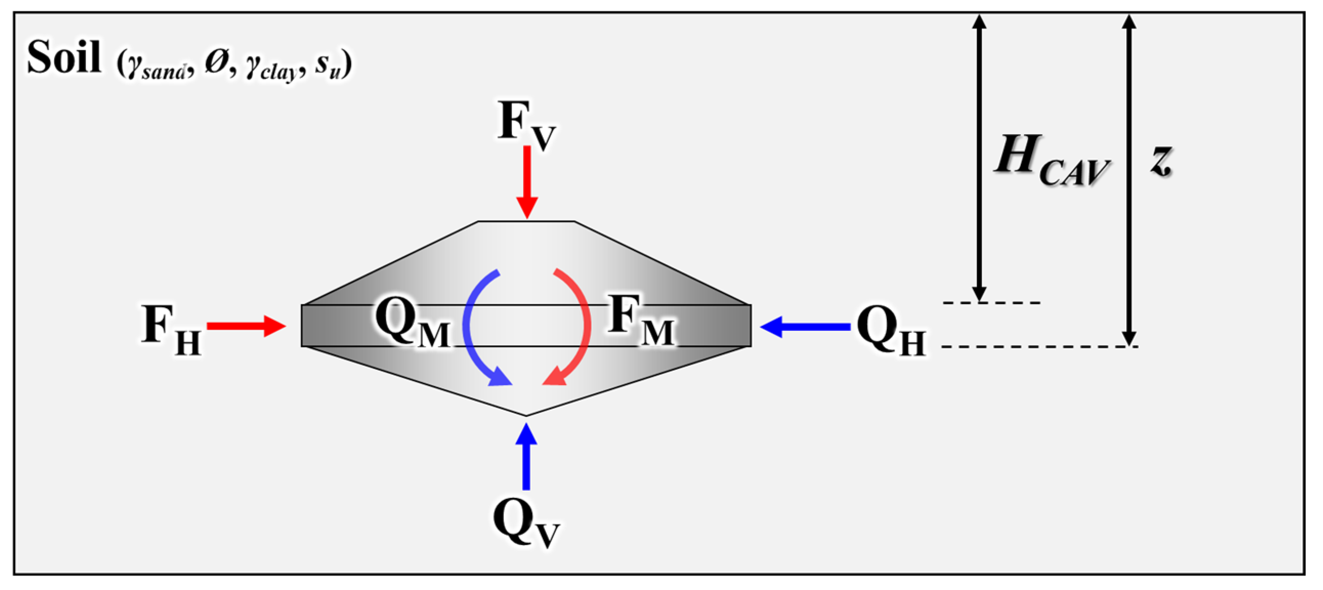
The horizontal force (FH), gross vertical force (FV), and moment (FM) acting on the spudcan, as shown in Figure 3 with capacities, are the forces transferred to the foundation by the jack-up under operational environmental conditions. If the force combination of FV, FH, and FM in Equation (11) is equal to zero for the interaction yield surface, then this combination lies on the yield surface. A force combination greater than zero lies outside the yield surface, whereas a force combination less than zero lies inside. This is a suitable non-yielding design condition.
F H Q H 2 + F M Q M 2 16 1 a F V Q V 2 1 F V Q V 2 4 a F V Q V 1 F V Q V
The horizontal and moment capacities (QH and QM) of the spudcan in clay or sand are calculated as a function of the net vertical bearing capacity (QVnet), as shown in Equations (12) and (13) for clay and Equations (14) and (15) for sand. The weight of the soil on the spudcan does not affect the horizontal and moment capacities in clay. Applying the net vertical bearing capacity in the sand layer is conservative because it neglects the increase in capacity due to the weight of any soil on the spudcan. However, it is proven to have a beneficial effect on the capacities.
Q H = 1 + s u a s u 0 0.11 + 0.39 A s A Q V , c l a y p 0 A
Q M = 0.1 + 0.05 a 1 + 0.5 z H C A V z B × Q V , c l a y p 0 A
where QV,clay is the ultimate vertical bearing capacity in clay. The depth interpolation parameter (a) is z/2.5B for z < 2.5B and 1.0 for z ≥ 2.5B. HCAV is the cavity depth that remains open above the spudcan and z is the penetration depth from the ground surface.
Q H = 0.12 × Q V , s a n d p 0 A
Q M = 0.075 B × Q V , s a n d p 0 A
where QV,sand is the ultimate vertical bearing capacity in sand.
When the jack-up spudcan is located in the sand layer, the value of a in Equation (11) is zero, as shown in Equation (16). According to Templeton et al. and Templeton [34,35], finite element analysis results indicate that negligible error is incurred by assuming a = 0 for embedment depths less than 0.3B and a = 1 for embedment depths greater than 1.7B.
F H Q H 2 + F M Q M 2 16 F V Q V 2 1 F V Q V 2 = 0
When calculating the yield envelope for vertical and horizontal bearing capacities, the moment bearing capacity is considered as 0. On the other hand, when calculating the yield envelope for vertical and moment bearing capacities, the horizontal bearing capacity is assumed as 0.

3. New Jack-Up Substructure Design Conditions

The prototype design of the new jack-up substructure investigated in this study is adopted from the previous work completed by a joint industry project, where the authors participated and are responsible for the geotechnical design of the jack-up structure including the spudcans published in [5,6]. The jack-up substructure of this study is illustrated and is supported by spudcan tips and cylindrical legs, as shown in Figure 4.
We considered a multi-layered soil condition consisting of combined sand and clay soils, as discussed in Section 3.1. Three diameters of spudcans were analyzed in order to select the size of the foundation suitable for the soil and environmental load conditions, and the details are discussed in Section 3.2.

3.1. Site Conditions

The prototype of the jack-up used in this study was designed for one of the Korean southwestern seabed conditions and is under development for offshore wind farms. It was deposited with multiple layers—top loose sand, clay, and dense sand—as summarized in Table 2. Thus, the soil model was designed with three layers—silty sand (loose condition)–clay–silty sand (dense condition) layers—as tabulated in Table 2.

3.2. Model Foundation Cases

The substructure is composed of tubular legs (similar to pile shape) and a tip of the spudcan-type foundation. Three spudcan sizes are analyzed in order to determine the size of the foundation suitable for the model conditions described in Section 3.1. The bearing capacity of the spudcan is examined for diameters of 4, 6, and 8 m. The applicable vertical load for preloading has a maximum value of 47.5 MN per spudcan foundation (i.e., design vertical load), which is calculated through structural stability analysis using the integrated load analysis (ILA) method of the upper superstructure, considering the self-weight of the substructure with the 10 MW turbine. The embedded length of the foundation located between the clay and the lower strong sand interface is 8.5 m, where the spigot of the spudcan footing is embedded in the lower sand and the shoulder of the spudcan is located at the interface. The total lengths of each foundation (spigot tip to the ground surface distance) are 9.24, 9.9, and 10.37 m. The spudcan diameter of 4 m did not consider backfill, since the spudcan shoulder and the pile diameter have the same value. All foundation types have a constant pile leg diameter of 4 m and embedded depth, as shown in Table 3 and Figure 5. The spigot of the spudcans has a constant angle of 76° and the angle from the shoulder to the spigot is 13° in all cases [13,36,37].

3.3. Experimental Verification for Vertical Capacity

3.3.1. Centrifuge Model Test

A centrifugal model test was conducted to validate the theoretical analysis method. Centrifuge modeling is an experimental technique used to replicate the in situ stress conditions of a prototype site by subjecting a scaled soil–structure model to high rotational speeds, thereby generating centrifugal forces. When a centrifugal acceleration of Ng is applied, the stress state at a given depth in a 1/N-scale centrifuge model becomes equivalent to that at the corresponding depth in the prototype. The scaling factors of the major physical quantities followed the scaling law of centrifuge modeling of [38].
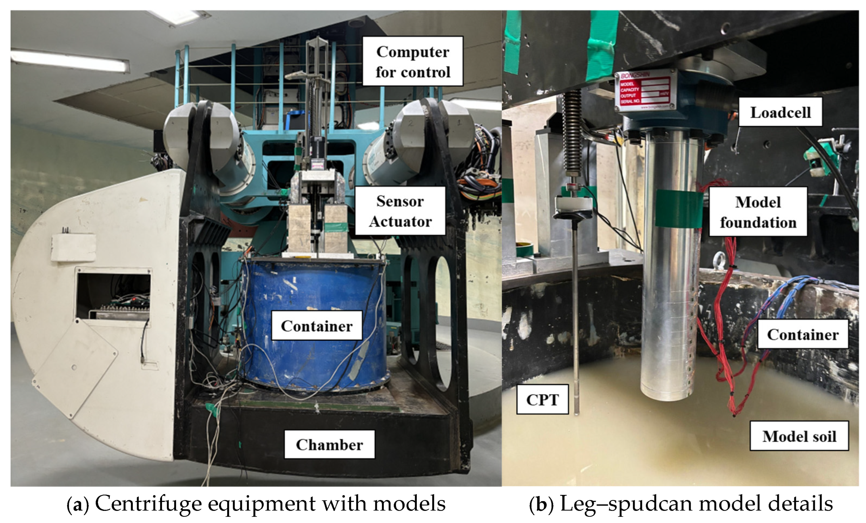
The test in this study was carried out at 50× g centrifugal acceleration (i.e., 1/50 scale used to prepare centrifuge models in this study) at the KOCED Geotechnical Centrifuge Testing Center, Korea Advanced Institute of Science & Technology (KAIST) in Daejeon, the Republic of Korea [39,40,41]. The facility includes a 5 m radius geotechnical centrifuge. The centrifuge equipment is driven by electric motors to create centrifugal acceleration, which is performed by the spinning speed of the equipment.
The platform where the soil model is mounted is located at the end of the centrifuge arm. The soil model is contained in a circular container, on which sensors with loading actuators are secured, as shown in Figure 6. The load generated when penetrating the spudcan in the vertical direction is measured by a TCLK-50KN loadcell installed between the head of the spudcan–leg model and the vertical actuator. The computer for measuring data is installed in a cabinet at the center of the centrifuge and is installed to rotate with the equipment; this computer is remotely controlled and communicated with using the Fiber Optic Rotary Joint (FORJ).

3.3.2. Test Condition

The experiments were designed to model the design site conditions introduced in Section 3.1. Details of the centrifuge modeling setup are referred from the previous paper [6]. The conditions of soil and foundation models are presented in Table 4 and Table 5, respectively. A scaling factor of 50 was applied to design the experiment. The jack-up substructure design is targeted for typical weak and complicated soil conditions in a Korean southwestern offshore seabed, which is deposited with multiple layers composed of top silty sand–clay–bottom silty sand.
The container used to form the soil models is cylindrically shaped and made of steel with an inner diameter of 895 mm and an inner height of 705 mm, large enough to avoid boundary effects [42]. The container contains a soil model simulating a prototype of the soil bed with a diameter of 44.75 m and a height of 35.25 m in the prototype scale at 50 g.
The silty sand in the first layer was prepared under loose conditions by underwater pluviation [43]. The sand layer was simulated with crushed silica sand (mean grain size, d50 = 0.151) and the grain size of sand and the model structure size were carefully selected to achieve a negligible effect of grain size by obtaining a small enough ratio of the grain size to structure diameter [44,45]. The second layer, consisting of kaolin clay, was formed by mixing water and kaolin clay at water contents (w) twice the liquid limit (LL), followed by consolidation until 800 kPa, of which LL is 78.15% and PI (plasticity index) is 46.33%. The bottom sand layer was prepared using dry pluviation to achieve a dense condition with a relative density over 92%, and after sand pluviation, water was gradually added to the soil to achieve 100% saturation.
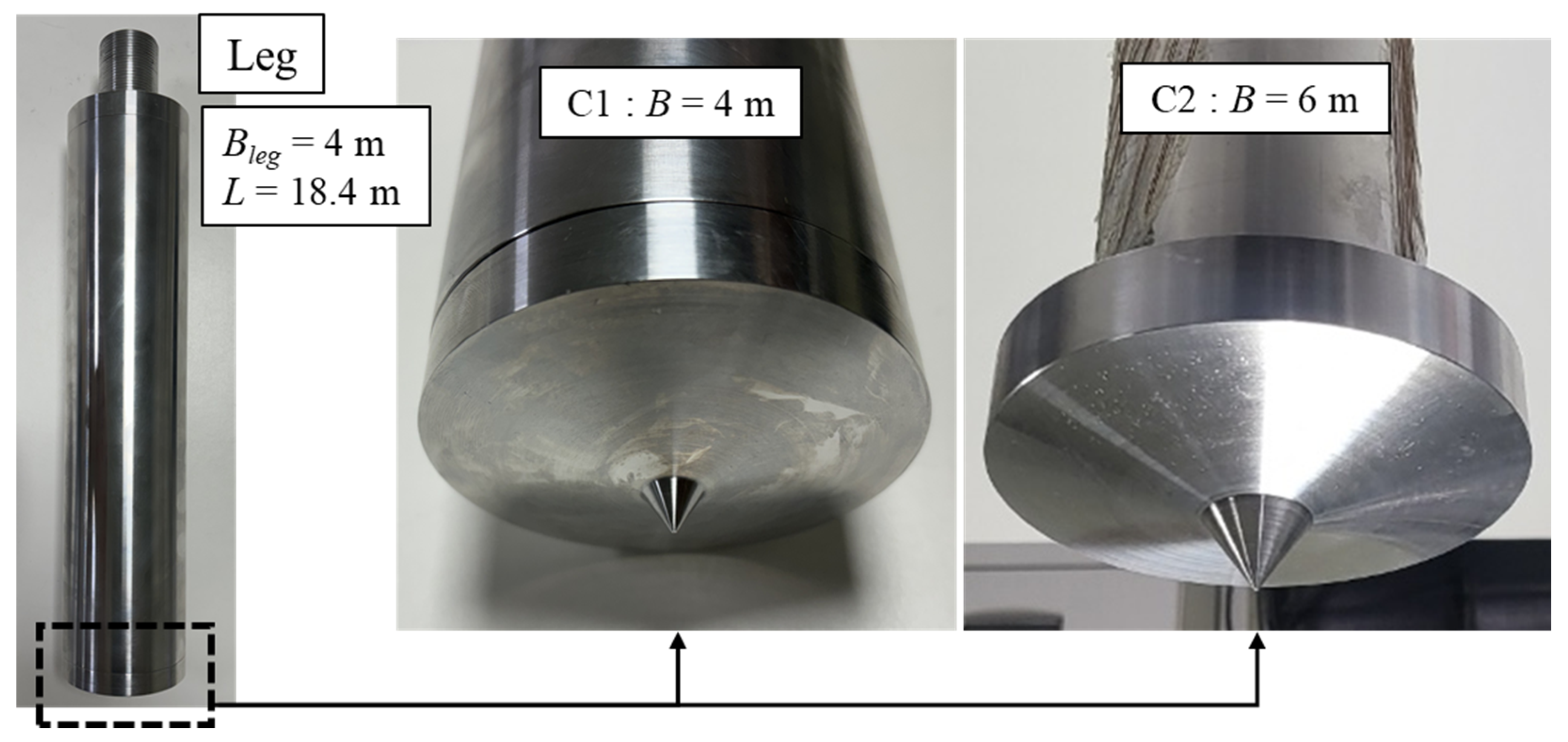
The model footings comprised a spudcan at the tip, with the pile-type leg in Figure 7. The C1 and C2 cases are for the same soil conditions, and differ only in the diameter of the spudcan. A scale model of a spudcan and leg was fabricated using an aluminum alloy with an equivalent EI of the prototype steel foundation. Each prototype dimension of the model foundations is similar to the 4 and 6 m diameter foundations in Figure 5.
The boundary effect, in terms of the distance from the foundation center to the container walls (LBD) relative to the spudcan diameter (B), was evaluated based on the findings of [46]. In the experiments conducted in this study, the boundary lengths were 5.625B for C1 and 3.75B for C2 with rigid wall chamber conditions. Compared with the recommendations of [46], which suggest a minimum boundary length of 1.5B for clay and 5B for sandy or composite soil conditions, C1 is expected to experience minimal boundary effects, whereas C2 may be influenced by boundary effects. However, since LBD/B is greater than 3, the boundary effect is estimated to remain within a 5% variation and is therefore unlikely to significantly affect the results.

4. Results

4.1. Vertical Capacities of Jack-Up Spudcans

Both the ISO and InSafeJIP methods were applied for the analysis of the foundation models, as summarized in Table 6. The vertical bearing capacity was evaluated by the models for theoretical analysis introduced in Section 2.1 up to the maximum penetration depth of the largest model, which had a diameter of 8 m. The same soil parameters and foundation dimensions were applied throughout.
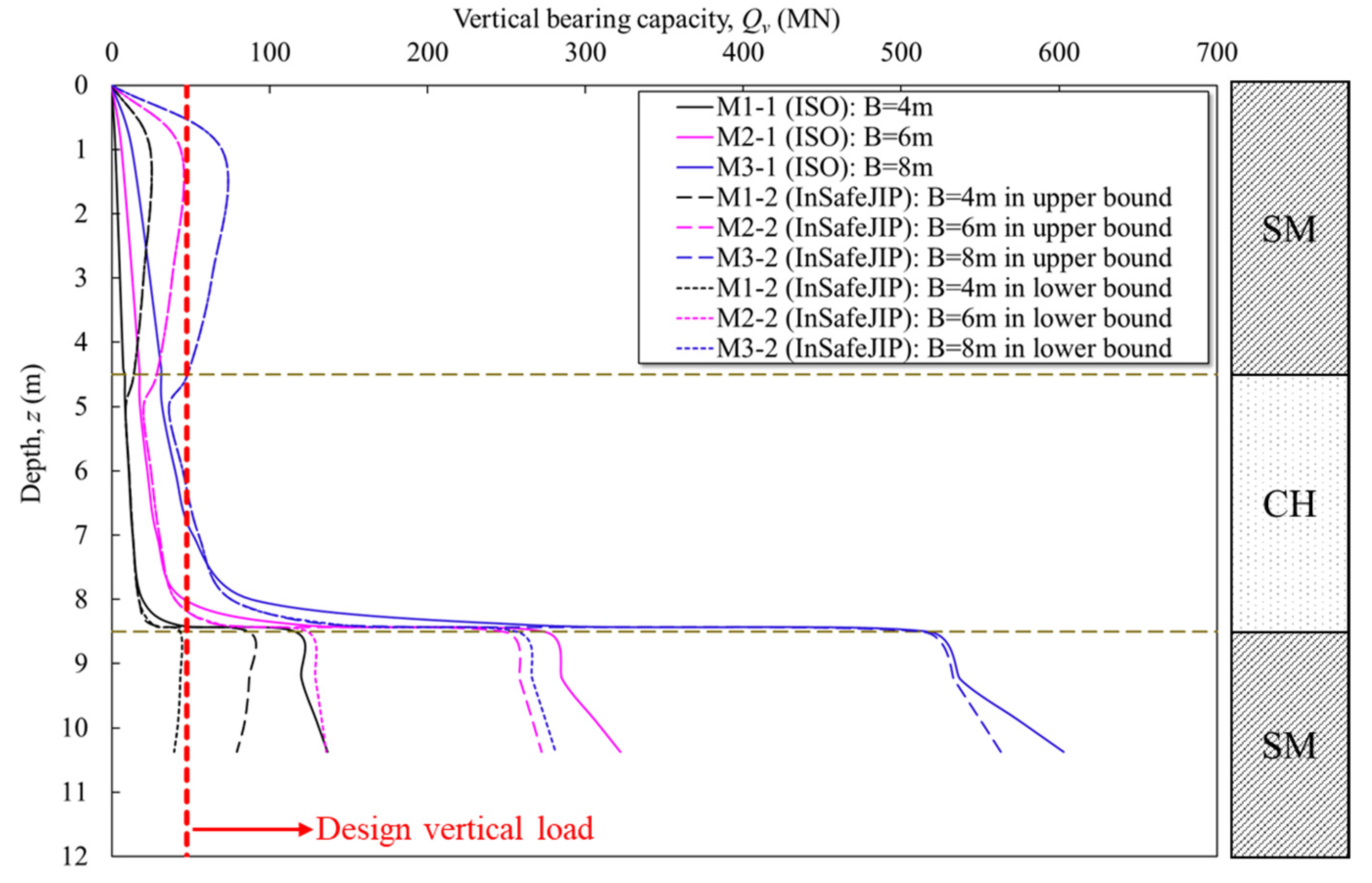
The expected vertical bearing capacity during installation is calculated using ISO and InSafeJIP methods (presented in Section 2) for three spudcans with diameters of 4, 6, and 8 m in layered soils, as shown in Figure 8. As described in Section 2, the calculations were carried out considering the squeezing and punch-through mechanisms formulae. In the cases of M1-2 to M3-2 by the InSafeJIP method, calculations were performed for both the lower bound (Fmob = 0.25) and upper bound (Fmob = 0.5) values of Fmob. In the cases of M1-1 to M3-1, Fmob was not applied. Instead, the vertical bearing capacity was calculated by reducing the friction angle (Ø) proposed by SNAME [17] by 5 degrees.
To estimate the penetrable depth of a jack-up system capable of mobilizing up to 47,502 kN (i.e., design vertical load in Figure 8) of vertical load during preloading, the depth for a spudcan with a diameter of 4 m was inferred to correspond to the interface between the intermediate clay and the underlying sand layer. To reproduce comparable penetration conditions for the theoretical validation using centrifuge model tests (Section 4.2), an embedment depth of 8.5 m was applied.
The spudcan’s shoulder is penetrated until the clay–sand interface is reached (z = 8.5 m) (strong sand surface with high strength), to prevent the foundation from settling down during the operation period of the substructure system. As a result, in the ISO method, the vertical bearing capacities at the tip increase as the diameter of the spudcan increases. At a depth of 8.5 m (i.e., spudcan bearing area position), M1-1 (B = 4 m) shows an ultimate vertical bearing capacity of 116,298 kN, that for M2-1 (B = 6 m) is 274,089 kN, and that for M3-1 (B = 8 m) is 517,351 kN. When the diameter of the spudcan increased from 4 to 6 m, the vertical capacity increased by about 2.4 times, and from 6 to 8 m, it increased by about 1.9 times. For all spudcan diameters, the capacity in the calculation using the single sand equation was smaller than those calculated by the squeezing mechanism.
Compared to the squeezing formula results, the ultimate vertical bearing capacity considering a single sand layer was lower by 59% in M1-1, 72% in M2-1, and 76% in M3-1. The rapid increase in capacity when considering squeezing in the clay bottom (near the clay–sand interface) is primarily attributed to the thickness of the weaker clay layer beneath the spudcan, denoted as T in Equation (1). In particular, the capacity increases significantly when T decreases below 1.0 m. Moreover, punch-through did not occur at the sand–clay interface (z = 4.5 m) using the ISO method with increasing spudcan diameter. However, the ultimate capacities increased rapidly as it penetrated into the strong sand layer at the bottom.
To address the limitations of the ISO method regarding interface boundary conditions, the InSafeJIP approach was added to evaluate the bearing capacity. The results showed good agreement in the intermediate clay layer, but significantly overestimated the potential for punch-through. In the dense sand layer, where the tip of the spudcan foundation was embedded, the predictions were within a reasonable range compared to those of the ISO method under lower bound conditions.

4.2. Experimental Validation of Vertical Capacity

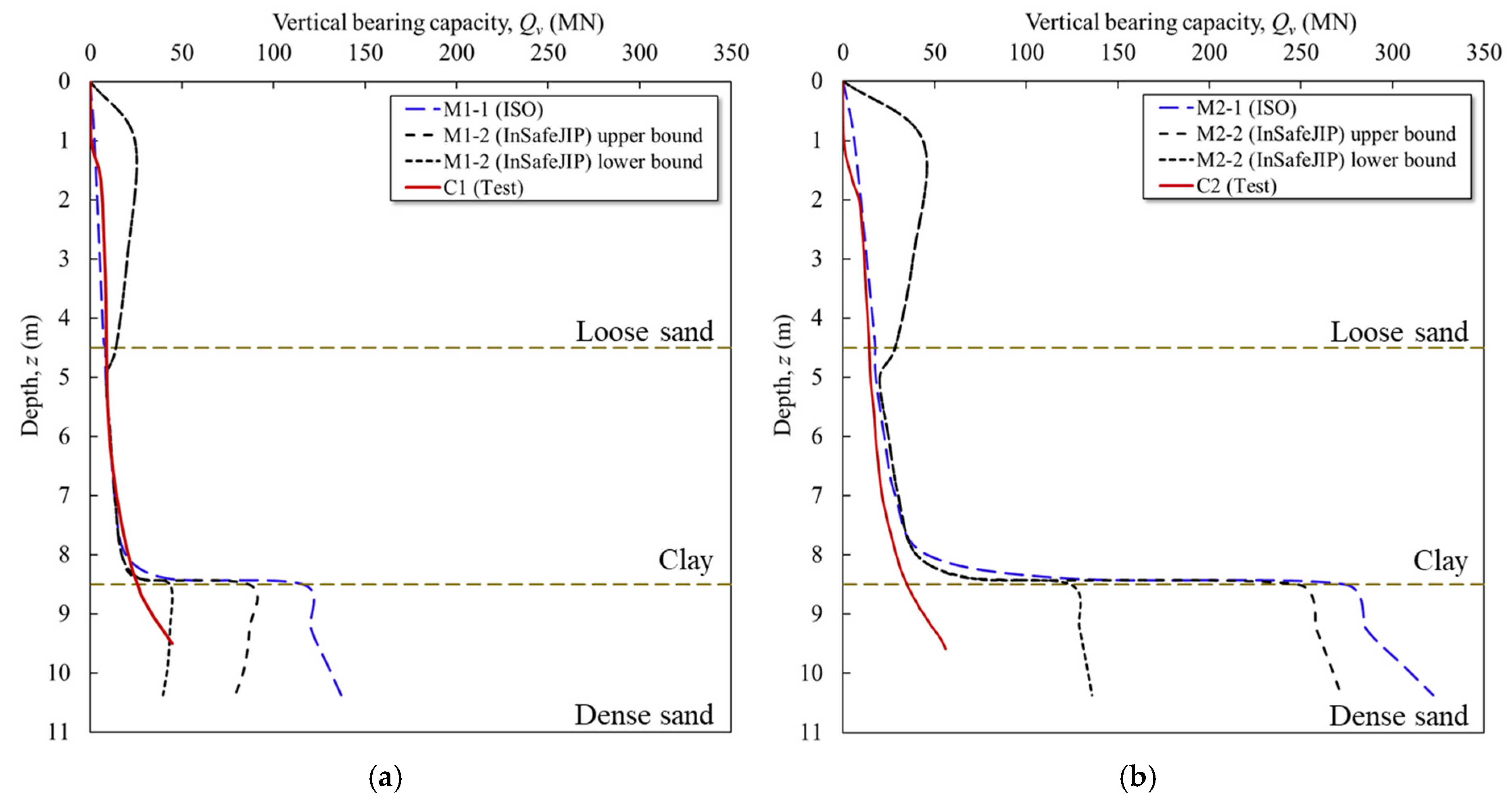
To evaluate the adequacy of the bearing capacity estimated using the proposed method, the results were compared from centrifuge model tests. The experimental results were compared with the theoretical calculations for the corresponding model cases in Figure 9. The soil and structure model properties applied in the experiment were identical to those used in the theoretical analysis.
When compared with the experimental results, the initial penetration behavior showed good agreement with the values calculated using the ISO method, particularly in predicting the bearing capacity when a clay layer was beneath the sand. Where clay overlay sand, both theoretical methods exhibited slight differences in the upper clay layer, but showed similar trends overall. In the lower sand layer, the ISO method using bearing capacity factors from [24] produced significantly higher capacities.
The InSafeJIP method, on the other hand, yielded results that closely matched the experimental data for a diameter of 4 m. Although some discrepancy was observed when the diameter increased to 6 m, the deviation was smaller than that observed with the ISO method. However, when the diameter exceeded the size of the leg (see Figure 9b), a greater deviation was observed between the results calculated using the theoretical formula and the experimental results. This is attributed first to a difference in the soil failure mechanisms during penetration of the spudcan foundation, caused by the effect of layered soil conditions formed during the experiment. Additionally, when sand raining the dense sand layer in the lowest layer, the depth near the base of the container for the centrifuge tests is limited to a high drop height during deposition, making it difficult to achieve dense compaction. Moreover, the influence of water injection leads to a looser state than initially designed compared to dry conditions.
The vertical bearing capacities used for yield surface determination corresponding to a penetration depth of 8.5 m were 43,468, 124,097, and 256,521 kN for spudcan diameters of 4, 6, and 8 m, respectively. These values, in the lower-bound cases of M1-2 to M3-2 by using the InSafeJIP method, were predicted to be 50~63% lower than those estimated by the ISO method.
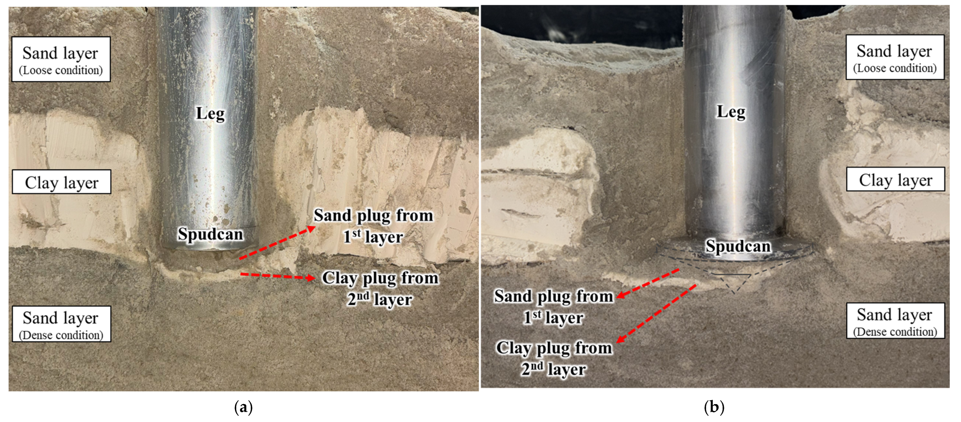
The soil behavior after model foundation penetration to a depth of 8.5 m (maximum depth achievable under the designed vertical load) is shown in Figure 10. The soil plug, formed during penetration through the first and second clay layers, was trapped between the sand layer at the base of the foundation and the cross-section of the spudcan. This phenomenon was observed for both the 4 and 6 m diameters of the spudcan. The size of the soil plug was smaller than that predicted by the theoretical formula, which appears to have resulted in lower vertical bearing capacity values measured in the experiments.
When a spudcan penetrates from the ground surface into a soil profile consisting of sand overlying clay, the sand beneath the spudcan is compressed against its underside, forming a sand plug. This plug leads to an increase in penetration resistance as the spudcan advances into the underlying clay. Additionally, in this study, the intermediate clay layer also resulted in the formation of a clay plug beneath the sand plug. Combined with the squeezing effect, this condition produced large penetration resistance when the spudcan reached the bottom hard sand layer. However, once the spudcan is fully embedded up to the intermediate clay, incorporating the effect of the soil plug in estimating the foundation tip resistance tends to overestimate the actual bearing capacity compared to the estimation of guidelines for pure single clay. Therefore, when evaluating the vertical bearing capacity of the foundation for its operation period in practice, the weight of the soil plug should also be excluded to consider punch-through failure. The soil plug weight effect should be appropriately accounted for using the concept of an equivalent diameter, as expressed in Equation (2).

4.3. Capacity Yield Envelopes for Combined Horizontal Load and Moment

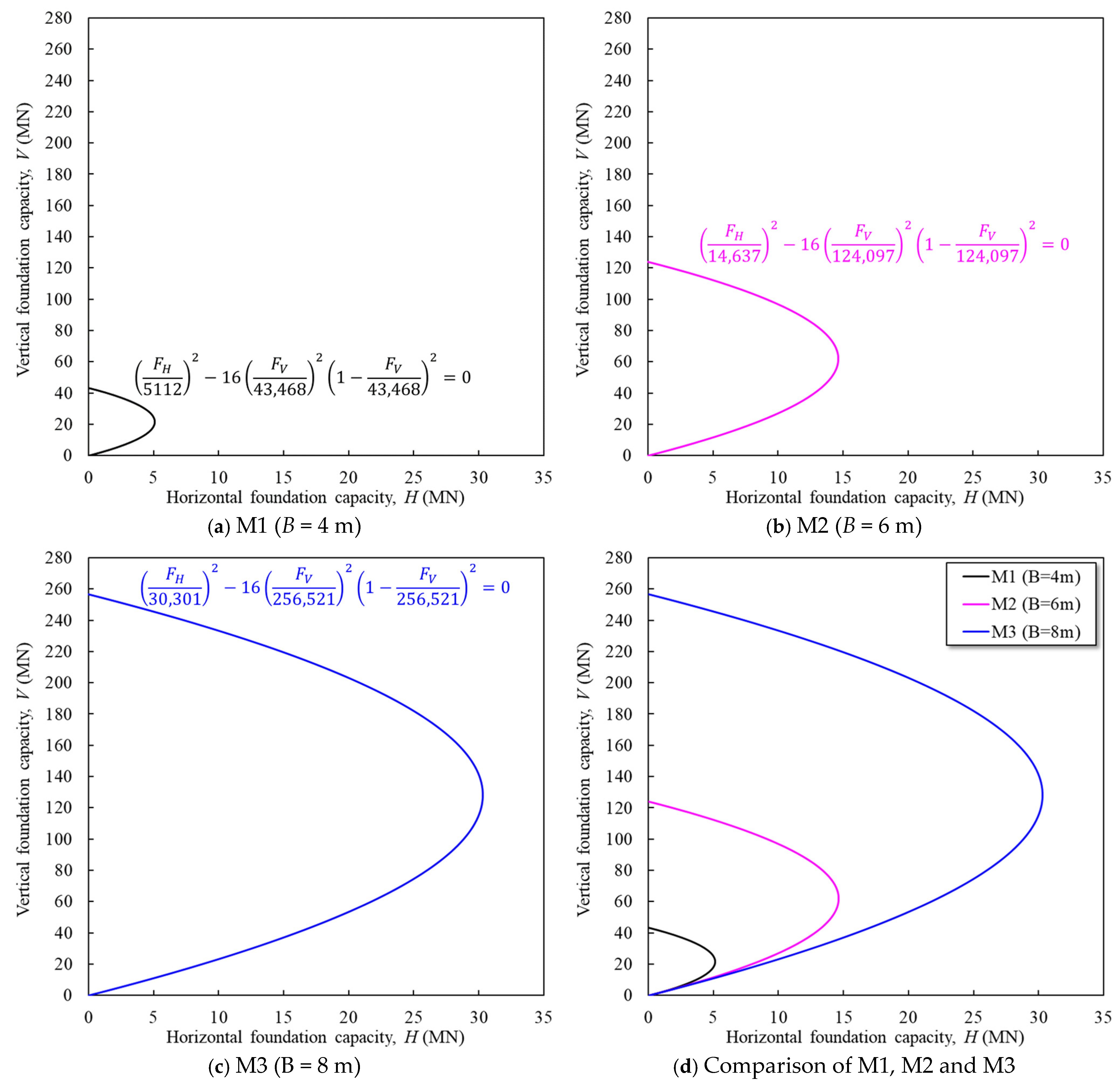
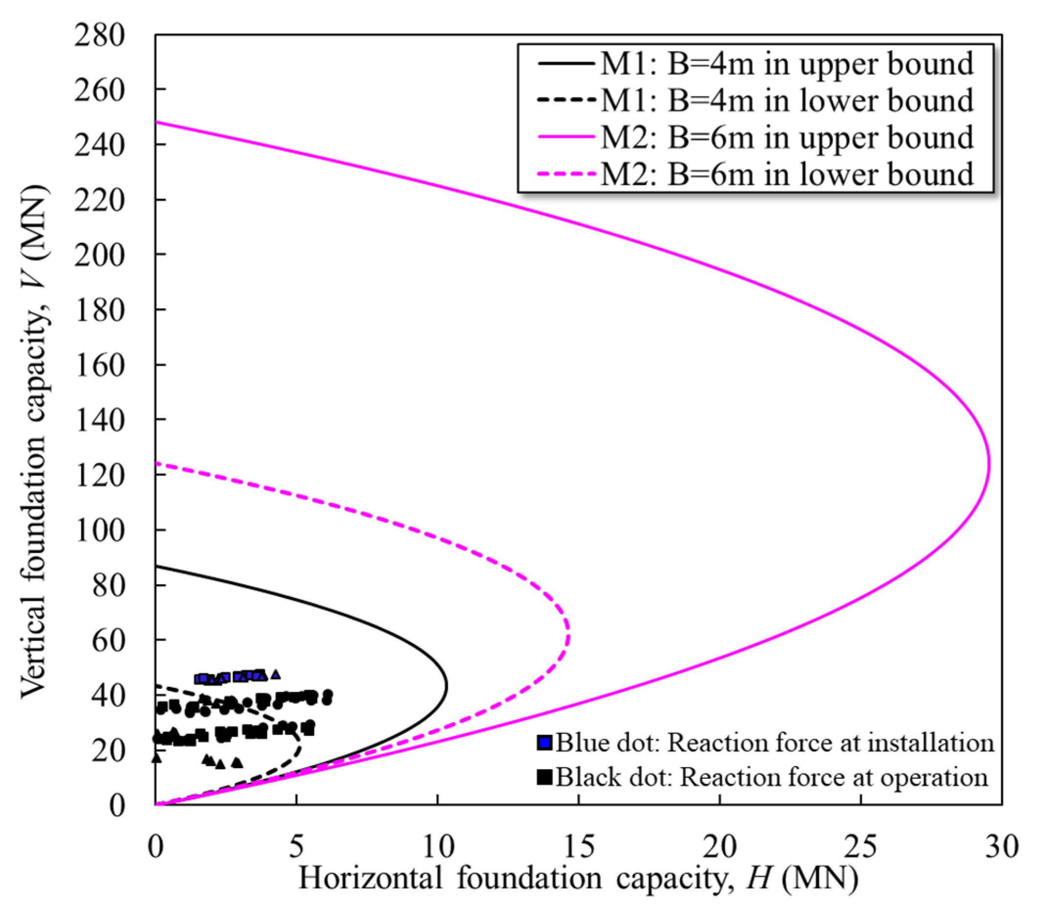
The ultimate horizontal and moment bearing capacities were derived using the previously estimated ultimate vertical bearing capacity. These were then applied to Equation (16) to formulate the yield surface expressions, as summarized in Table 7, with an assumption that the spudcan’s shoulder is penetrated until the clay–sand interface is reached (z = 8.5 m).
The vertical–horizontal foundation capacity failure envelopes used in the foundation capacity step of the ISO guideline acceptance check are plotted in Figure 11. Load combinations lying within the respective yield surfaces of M1, M2, and M3 are deemed to represent stable design conditions. An increase in spudcan diameter results in a corresponding enlargement in the yield surface.
The reaction forces extracted from ILA for the 10 MW OWT are shown in Figure 12. In the case of a spudcan with a diameter of 4 m, the reaction forces exceeded the yield surface under the lower bound condition, as illustrated in Figure 10, indicating that a stable support cannot be ensured. Thus, the spudcan diameter was increased to 6 m, allowing for stable bearing performance. However, if the actual soil conditions correspond to a stiff ground and the upper bound condition with Fmob = 0.5 is applied, sufficient support can be achieved for a spudcan diameter of 4 m.

5. Discussion and Recommendation for Practice

In the design of jack-up spudcan foundations, acceptance checks are a critical requirement. The ultimate bearing capacity is assessed to ensure it can resist vertical loads resulting from preloading of the leeward and windward legs, as discussed earlier. The vertical–horizontal foundation capacity and the sliding check against spudcan reaction forces should be assessed using vertical–horizontal capacity envelopes. It is essential to perform displacement checks, since exceeding the yield surface may lead to settlement or sliding, particularly under conditions susceptible to punch-through.
In this study, the applicability of jack-up foundation design was assessed for one of the typical Korean offshore seabed conditions. The stratigraphy of the target site consists of a weak sand layer overlying clay, underlain by strong sand. The analysis was conducted using a model in which the shoulder of the spudcan is positioned at the interface of the clay–bottom sand stratum.
Among the current design guidelines, the ISO method shows good agreement, especially in the vertical capacity calculation under the sand-over-clay and clay conditions with the experimental results, and is therefore considered appropriate to use in design. However, when analyzing the behavior of spudcan foundations in sandy soils, the design equations predicted high vertical capacity. It appears appropriate to adopt coefficients or methodologies, such as the mobilization factor proposed in the InSafeJIP guidelines, to account for strength reduction similar to real offshore soil behavior.
The vertical–horizontal capacity envelopes of the spudcan foundation, considered the most critical aspect of the acceptance check procedure, was evaluated. It was observed that the surface of the yield envelope increases with increasing spudcan diameter. As the spudcan diameter increases, the bearing area of the foundation tip also increases, resulting in a significant increase in vertical bearing capacity. Additionally, the formation of backfill on the spudcan shoulder, and the formation of sand or stiff clay plugs, leads to an additional increase in vertical bearing capacity, especially when reaching the hard sand layer. Since this may lead to an overestimation of the tip resistance, the soil plug weight should be excluded, and its effect should be considered through the equivalent diameter concept (Equation (2)) or experiments replicating in situ stress conditions.
The suitability of the spudcan model proposed in this study was evaluated using the estimated foundation reaction forces derived from ILA. For an offshore wind turbine with a rated capacity of 10 MW, the spudcan was designed with a diameter of 6 m and a leg diameter of 4 m. Consequently, this approach can be used to define the foundation dimensions for offshore wind turbine support structures.

6. Conclusions

The conclusions of this study are summarized as follows:
  • This study evaluated the applicability of a jack-up spudcan foundation design for typical Korean offshore seabed conditions consisting of a weak sand layer over clay, underlain by dense sand.
  • The ISO design method showed good agreement with the experimental results for sand-over-clay and clay conditions; however, it tended to overestimate vertical capacity in sandy soils. Thus, considering strength reduction factors, such as the mobilization factor from the InSafeJIP method, is recommended to better predict the actual offshore soil behavior to design the foundation.
  • Vertical–horizontal capacity envelopes expanded with spudcan diameter due to the larger bearing area and the formation of backfill on the spudcan shoulder.
  • Finally, this study examines the influence of spudcan foundation size and the effects of multi-layered ground conditions, provides a foundation design based on integrated load analysis, and investigates a methodology for selecting an appropriate foundation for a 10 MW offshore wind turbine substructure.
  • The current study aims to establish design procedures for an offshore three-leg jack-up substructure equipped with a spudcan installed in multiple layers for short-term performance. The result of the current work is limited to the short-term loading condition. Thus, further study is necessary to verify the long-term performance under cyclic loading.

Author Contributions

Conceptualization, Y.W.C.; methodology, M.J.L.; software, M.J.L.; validation, M.J.L. and Y.W.C.; formal analysis, M.J.L.; investigation, M.J.L.; resources, M.J.L.; data curation, M.J.L.; writing—original draft preparation, M.J.L.; writing—review and editing, Y.W.C.; visualization, Y.W.C.; supervision, Y.W.C.; project administration, Y.W.C.; funding acquisition, Y.W.C. All authors have read and agreed to the published version of the manuscript.

Funding

This work was supported by the Korea Institute of Energy Technology Evaluation and Planning (KETEP) and the Ministry of Trade, Industry & Energy (MOTIE) of the Republic of Korea (No. RS-2022-KP002820).

Data Availability Statement

The original contributions presented in this study are included in the article. Further inquiries can be directed towards the corresponding author.

Conflicts of Interest

The authors declare no conflicts of interest.

References

  1. Choo, Y.W.; Kim, D.; Park, J.H.; Kwak, K.; Kim, J.H.; Kim, D.S. Lateral Response of Large-diameter Monopiles for Offshore Wind Turbines from Centrifuge Model Tests. Geotech. Test. J. 2014, 37, 107–120. [Google Scholar] [CrossRef]
  2. Kim, D.; Choo, Y.W.; Kwak, K. Comparison of Lateral Behavior of Rock-socketed Large-diameter Offshore Monopiles in Sands with Different Relative Densities. Int. J. Offshore Polar Eng. 2015, 25, 156–160. [Google Scholar] [CrossRef]
  3. Kim, D.J.; Choo, Y.W.; Kim, J.H.; Kim, S.; Kim, D.S. Investigation of Monotonic and Cyclic Behavior of Tripod Suction Bucket Foundations for Offshore Wind Towers Using Centrifuge Modeling. J. Geotech. Geoenviron. Eng. 2014, 140, 04014008. [Google Scholar] [CrossRef]
  4. Choo, Y.W.; Seo, J.H.; Kim, Y.N.; Goo, J.M.; Kim, Y.H. Numerical Studies on Piled Gravity Base Foundation for Offshore Wind Turbine. Mar. Georesour. Geotechnol. 2016, 34, 729–740. [Google Scholar] [CrossRef]
  5. Shin, M.Y.; Sung, J.Y.; Park, C.I.; Kim, H.K. Introduction to 10 MW Jack-up Type Fixed Offshore Wind Power Design (K-WIND). In Proceedings of the 2023 Fall Conference of the Korea Society of Ocean Engineers, Gyeongju, Republic of Korea, 25–27 October 2023; pp. 162–163. [Google Scholar]
  6. Lee, M.J.; Choo, Y.W. Penetration Behavior of Jack-up Leg with Spudcan for Offshore Wind Turbine to Multi-layered Soils Using Centrifuge Tests. J. Ocean Eng. Technol. 2024, 38, 30–42. [Google Scholar] [CrossRef]
  7. Howarth, S.; Hassrick, J.; Grismala, R.; Diller, E.; Kerbs, J.; Manhard, R. Comparison of Environmental Effects from Different Offshore Wind Turbine Foundations. In Report No. OCS Study BOEM 2020-041; U.S. Department of the Interior: Sterling, VA, USA, 2020. [Google Scholar]
  8. Choo, Y.W.; Lee, M.J.; Hong, I.B. Technical Consideration on Jackup-spudcan Structures for Offshore Wind Substructure. In Proceedings of the 2023 Fall Conference of the Korea Society of Ocean Engineers, Gyeongju, Republic of Korea, 25–27 October 2023; pp. 156–157. [Google Scholar]
  9. Gilo, A.; Lee, M.J.; Choo, Y.W. Numerical Analysis of the Effect of an Inverted Cone Angle on the Penetration Behavior of the Jack-Up Leg Foundation for Offshore Wind Turbines in Uniform Clay. J. Ocean Eng. Technol. 2024, 38, 438–448. [Google Scholar] [CrossRef]
  10. Kim, Y.J.; Choe, J.W.; Lim, J.; Choi, S.W. Foundation types of fixed offshore wind turbine. J. Ocean Eng. Technol. 2024, 38, 74–85. [Google Scholar] [CrossRef]
  11. Ali, S.; Park, H.; Lee, D. Multi-Criteria Optimization of Wind Turbines in an Offshore Wind Farm with Monopile Foundation Considering Structural Integrity and Energy Generation. J. Mar. Sci. Eng. 2024, 12, 2313. [Google Scholar] [CrossRef]
  12. Tran, T.T.; Lee, D. Development of jacket substructure systems supporting 3MW offshore wind turbine for deep water sites in South Korea. Int. J. Nav. Archit. Ocean Eng. 2022, 14, 100451. [Google Scholar] [CrossRef]
  13. Park, J.S.; Lee, D.H.; Yi, M.S. Structural Analysis Procedure and Applicability Review of Spudcan Considering Soil Types. J. Mar. Sci. Eng. 2023, 11, 1833. [Google Scholar] [CrossRef]
  14. Falcon, S.S.D.; Choo, Y.W.; Leung, C.F. Spudcan–pile interaction in sand-over-clay: Centrifuge modelling. Géotechnique 2023, 73, 480–494. [Google Scholar] [CrossRef]
  15. Baek, S.H.; Choi, C.; Cho, J.; Chung, C.K. Assessment of py Behaviors of a Cyclic Laterally Loaded Pile in Saturated Dense Silty Sand. J. Korean Geotech. Soc. 2019, 35, 97–110. [Google Scholar]
  16. ISO 19905-1:2023; Petroleum and Natural Gas Industries: Site Specific Assessment of Mobile Offshore Unit—Part 1: Jack-Ups Elevated at a Site. International Organization for Standardization (ISO): Geneva, Switzerland, 2023.
  17. The Society of Naval Architects and Marine Engineers (SNAME). Guidelines for Site Specific Assessment of Mobile Jack-Up Units; Technical & Reasearch Bulletin 5-5A; SNAME: Alexandria, VA, USA, 2008. [Google Scholar]
  18. Osborne, J.J.; Teh, K.L.; Houlsby, G.T.; Cassidy, M.J.; Bienen, B.; Leung, C.F. Improved Guidelines for the Prediction of Geotechnical Performance of Spudcan Foundations during Installation and Removal of Jack-up nits. In Offshore Technology Development; InSafeJIP; RPS Engergy: Abingdon, UK, 2011. [Google Scholar]
  19. Brown, J.D.; Meyerhof, G.G. Experimental Study of Bearing Capacity in Layered Clays. In Proceedings of the 7th International Conference on Soil Mechanics and Foundation Engineering, Mexico City, Mexico, 25–29 August 1969. [Google Scholar]
  20. Vesic, A.S. Bearing Capacity of Shallow Foundations, Winterkorn. In Foundation Engineering Handbook; Winterkorn, H.F., Fang, H.Y., Eds.; Van Nostrand: Scarborough, ON, Canada, 1975; pp. 121–147. [Google Scholar]
  21. Young, A.G.; Remmes, B.; Meyer, B. Foundation Performance of Offshore Jack-UP Drilling Rigs. J. Geotech. Eng. Geotech. 2012, 42, 89–97. [Google Scholar] [CrossRef]
  22. Houlsby, G.T.; Martin, C.T. Undrained Bearing Capacity Factors for Conical Footings on Clay. Geotechnique 2003, 5, 513–520. [Google Scholar] [CrossRef]
  23. Young, A.G.; Focht, J.A. Subsurface Hazards Affect Mobile Jack-up Rig Operations. Sounding 1981, 3, 4–9. [Google Scholar]
  24. Martine, C.M. User Guide for ABC—Analysis of Bearing Capacity; Department of Engineering Science, University of Oxford: Oxford, UK, 2004. [Google Scholar]
  25. Brinch Hansen, J. Revised and Extended Formula for Bearing Capacity; Bulletin in Danish Geotechnical Institute: Copenhagen, Denmark, 1970; Volume 28. [Google Scholar]
  26. Graham, J.; Stuart, J.G. Scale and Boundary Effects in Foundation Analysis. J. Soil Mech. Found. Div. 1971, 97, 1533–1548. [Google Scholar] [CrossRef]
  27. James, R.G.; Tanaka, H. An Investigation of the Bearing Capacity of footings under Eccentric and Inclined Loading in Sand in a Geotechnical Centrifuge. In Proceedings of the Symposium Recent Advances in Geotechnical Centrifuge Modelling, Davis, CA, USA, 18–20 July 1984; pp. 88–115. [Google Scholar]
  28. Kimura, T.; Kusakabe, O.; Saitoh, K. Geotechnical Model Tests of Bearing Capacity Problems in Centrifuge. Geotechnique 1985, 35, 33–45. [Google Scholar] [CrossRef]
  29. Lee, M.J.; Gilo, A.; Choo, Y.W. Geotechnical Analysis of Jack-Up Leg Mounted on Spudcan for Offshore Wind Turbines Considering Installation and Operation. In Proceedings of the International Conference on Offshore Mechanics and Arctic Engineering, Singapore, 9–14 June 2024; American Society of Mechanical Engineers: New York, NY, USA, 2024; p. V008T10A008. [Google Scholar]
  30. Meyerhof, G.G.; Hanna, A.M. Ultimate Bearing Capacity of Foundations on Layered Soils under Inclined Load. Can. Geotech. J. 1978, 15, 565–572. [Google Scholar] [CrossRef]
  31. Craig, W.H.; Chua, K. Deep Penetration of Spudcan Foundations on Sand and Clay. Géotechnique 1990, 40, 541–556. [Google Scholar] [CrossRef]
  32. Teh, K.L. Punch-Through of Spudcan Foundation in Sand Overlying Clay. Ph.D Thesis, National University of Singapore, Singapore, 2007. [Google Scholar]
  33. Lee, K.K. Investigation of Potential Spudcan Punch-Through Failure on Sand Overlying Clay Soils. PhD. Thesis, The University of Western Australia, Perth, Australia, 2009. [Google Scholar]
  34. Templeton, J.S.; Brekke, J.N.; Lewis, D.R. Spudcan Fixity in Clay, Final Findings of an IADC Study. In Proceedings of the 10th International Conference on Jack-Up Platform Design, Construction & Operation, London, UK, 13–14 September 2005. [Google Scholar]
  35. Templeton, J.S. Jackup Foundation Performance in Clay. In Proceedings of the 38th Offshore Technology Conference, OTC 18367, Huston, TX, USA, 1–4 May 2006. [Google Scholar]
  36. Falcon, S.S.D.; Choo, Y.W.; Leung, C.F. Pile Behavior due to Adjacent Jack-up Spudcan Penetration. Int. J. Offshore Polar Eng. 2021, 31, 472–479. [Google Scholar] [CrossRef]
  37. Falcon, S.S.D.; Sespene, S.M.; Choo, Y.W.; Leung, C.F. Model Study on Spudcan-pile Interaction in Uniform Clay and Sand-over-clay. In Proceedings of the 29th International Ocean Polar Engineering Conference, Honolulu, HI, USA, 16–21 June 2019; Volume 2, pp. 2042–2048. [Google Scholar]
  38. Schofield, A.N. Cambridge geotechnical centrifuge operations. Géotechnique 1980, 30, 227–268. [Google Scholar] [CrossRef]
  39. Kim, D.S.; Lee, S.H.; Choo, Y.W.; Perdriat, J. Self-balanced Earthquake Simulator on Centrifuge and Dynamic Performance Verification. KSCE J. Civ. Eng. 2013, 17, 651–661. [Google Scholar] [CrossRef]
  40. Yun, J.W.; Han, J.T. Dynamic Behavior of Pile-supported Wharves by Slope Failure during Earthquake via Centrifuge Tests. Int. J. Geo-Eng. 2021, 12, 33. [Google Scholar] [CrossRef]
  41. Yun, J.S.; Park, S.J.; Falcon, S.S.; Han, J.T.; Kim, D.; Choo, Y.W. Seismic Response of Braced Excavation Wall Supporting Deep Sand Layer Using Dynamic Centrifuge Tests. Soil Dyn. Earthq. Eng. 2024, 183, 108782. [Google Scholar] [CrossRef]
  42. Sakr, M.; Nasr, A.; Khaffaf, M.; Basha, A. Behavior of Under-reamed Piles under Inclined Uplift Loads in Sand. Int. J. Geo-Eng. 2025, 16, 9. [Google Scholar] [CrossRef]
  43. Raju, K.V.S.B.; Lakshmi, V. Pullout and Oblique Pullout Resistance of Enlarged Base Piles in Geogrid Reinforced Sand. Int. J. Geo-Eng. 2025, 16, 12. [Google Scholar] [CrossRef]
  44. Basha, A.M.; Eldisouky, E.A. Effect of Eccentric Loads on the Behavior of Circular Footing With/without Skirts Resting on Sand Soil. Int. J. Geo-Eng. 2023, 14, 13. [Google Scholar] [CrossRef]
  45. Park, S.; Kim, G.Y.; Chang, I. Experimental Study on the Effect of Surface-projected Conditions on the Mechanical Behavior of Pile Embedded in Sand. Int. J. Geo-Eng. 2024, 15, 22. [Google Scholar] [CrossRef]
  46. Ullah, S.N.; Hu, Y.; Stanier, S.; White, D. Lateral boundary effects in centrifuge foundation tests. Int. J. Phys. Model. Geotech. 2017, 17, 144–160. [Google Scholar] [CrossRef]
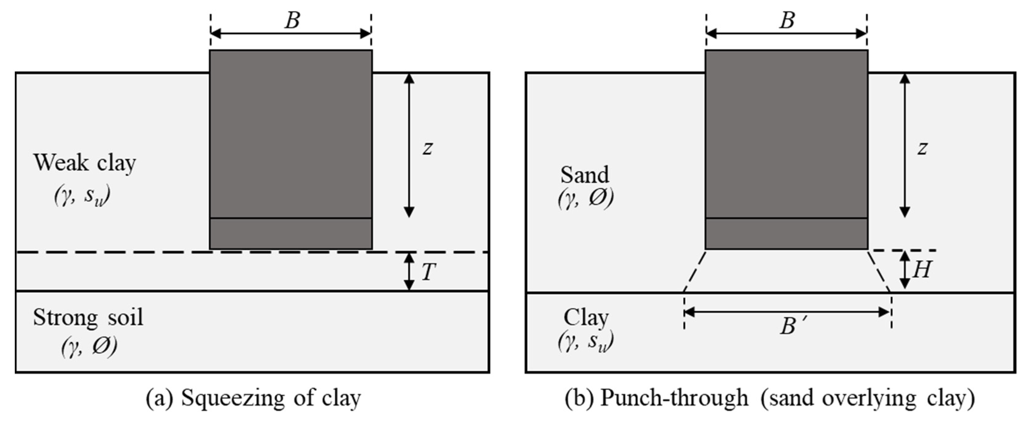
Figure 1. Spudcan foundation penetration in layered soil of ISO method.
Jmse 13 02060 g001
Figure 2. Nomenclature of spudcan penetration of two-layered soil in InSafeJIP method.
Jmse 13 02060 g002
Figure 3. The bearing capacities and forces in the spudcan.
Jmse 13 02060 g003
Figure 4. New jack-up substructure design.
Jmse 13 02060 g004
Figure 5. Dimensions of spudcans.
Jmse 13 02060 g005
Figure 6. Centrifuge model test.
Jmse 13 02060 g006
Figure 7. Model foundations of spudcan–leg type (dimension-prototype scale).
Jmse 13 02060 g007
Figure 8. Comparison of vertical bearing capacities of spudcans estimated by ISO and InSafeJIP formula.
Jmse 13 02060 g008
Figure 9. Comparison of the vertical capacity from the centrifuge tests, ISO, and InSafeJIP. (a) Vertical capacity of 4 m diameter spudcan. (b) Vertical capacity of 6 m diameter spudcan.
Jmse 13 02060 g009
Figure 10. Soil behavior after model foundation penetration in each case. (a) Soil behavior in C1 (B = 4 m). (b) Soil behavior in C2 (B = 6 m).
Jmse 13 02060 g010
Figure 11. Vertical–horizontal spudcan foundation capacity envelopes.
Jmse 13 02060 g011
Figure 12. Yield envelope assessment.
Jmse 13 02060 g012
Table 1. Comparison between ISO and InSafeJIP methods.
Conditions ISO MethodInSafeJIP Method
Punch-through mechanismUpper sand
Q v = Q u , b ( c l a y ) W ( s a n d )
Sand plug effect: W (weight of sand)
Loose to medium dense sand (25° < ϕ′ < 35°)>
Spudcan buoyancy effect: γ s a n d 2 h l a y e r 2 h 2 π B × K s tan ϕ
Lower clay
No calculation method is presented
Sand plug effect: 4 s u a h p l u g B
Squeezing mechanismUpper weak soil
Q v ( s q u e e z i n g )   >   Q v ( s i n g l e c l a y )
Boundary condition: B ≥ 3.45T(1 + 1.025z/B) for z/B ≤ 2.5
Determined based on the clay strength properties
Lower strong soil
No calculation method is presented
Assumed to be stiff clay
Reduction factorSand
Reduction in friction angle: Ø- 5° = Ø′
The mobilization factor (Fmob) = 0.25–0.5
Clay
No effect
No effect
Table 2. Prototype of soil condition.
Soil LayersDepth (m)Thickness (m)N-Value
Silty sand0~4.54.51~6/30
Clayey soil4.5~8.54.010~31/30
Silty sand8.5~10.72.246~50/30
Table 3. The properties of foundations.
ItemsFootingsLeg
TypeSpudcanPile
MaterialStainless steel (E 1 = 210 GPa)
Diameter, B (m)4, 6, 84 (all cases)
Embedded length, L (m)Full penetration8.5 from the spudcan shoulder
1 Young′s modulus of the materials.
Table 4. Soil conditions in centrifuge test (prototype scale).
Items1st Layer2nd Layer3rd Layer
Soil typeSilty sandClaySilty sand
Depth, z (m)0~4.54.5~8.58.5~10.7
Thickness (m)4.54.02.2
Relative density, Dr (%) -
Submerged unit weight, γ′ (kN/m3)8.2786.2079.395
Undrained shear strength, su (kPa)-85.175~161.514-
Friction angle, ϕ (°)28-42
Table 5. Dimensions of foundation testing model.
ModelsC1C2
(Scales)ModelPrototypeModelPrototype
Spudcan diameter, B (mm)8040001206000
Leg diameter, Bleg (mm)804000804000
Embedded length of foundation, Lem (mm)17085001708500
Table 6. Models for theoretical analysis.
Model NameSpudcan Diameter, B (m)Analysis Methodology
M1-14.0ISO method
for the vertical capacities
M2-16.0
M3-18.0
M1-24.0InSafeJIP method
for the vertical capacities
M2-26.0
M3-28.0
M14.0ISO method for vertical/horizontal/rotational capacity interaction function
M26.0
M38.0
Table 7. The yield envelope formula.
FoundationsThe Yield Interaction Formula
M1 (B = 4 m) F H 5112 2 + F M 12,780 2 16 F V 43,468 2 1 F V 43,468 2 = 0
M2 (B = 6 m) F H 14,637 2 + F M 54,887 2 16 F V 124,097 2 1 F V 124,097 2 = 0
M3 (B = 8 m) F H 30,301 2 + F M 151,507 2 16 F V 256,521 2 1 F V 256,521 2 = 0
Disclaimer/Publisher’s Note: The statements, opinions and data contained in all publications are solely those of the individual author(s) and contributor(s) and not of MDPI and/or the editor(s). MDPI and/or the editor(s) disclaim responsibility for any injury to people or property resulting from any ideas, methods, instructions or products referred to in the content.