Article

Effect of Hydrogen-Containing Fuel on the Mechanical Properties of an Aluminum Alloy ICE Piston

by
Jelena Škamat
1,
Olegas Černašėjus
2,
Saugirdas Pukalskas
3,* and
Raimonda Černašėjienė
2
1
Laboratory of Composite Materials, Vilnius Gediminas Technical University, Saulėtekio al. 11, LT-10223 Vilnius, Lithuania
2
Department of Mechanical and Materials Engineering, Vilnius Gediminas Technical University, Plytinės St. 25, LT-10105 Vilnius, Lithuania
3
Department of Automobile Engineering, Faculty of Transport Engineering, Vilnius Gediminas Technical University, Plytinės St. 25, LT-10105 Vilnius, Lithuania
*
Author to whom correspondence should be addressed.
J. Mar. Sci. Eng. 2025, 13(10), 1889; https://doi.org/10.3390/jmse13101889
Submission received: 31 August 2025 / Revised: 22 September 2025 / Accepted: 26 September 2025 / Published: 2 October 2025
(This article belongs to the Special Issue Ship Performance and Emission Prediction)

Abstract

The transition to cleaner, hydrogen-containing fuels is critical for reducing the environmental impact of marine infrastructure, yet their potential effects on the durability and mechanical reliability of engine components remain a significant engineering challenge. Although aluminum alloys are generally regarded as less susceptible to hydrogen-induced degradation and are widely applied in internal combustion engine components, experimental data obtained under real operating conditions with hydrogen-containing fuel mixtures remain insufficient to fully assess all potential risks. In the present study, two identical low-power gasoline engine–generators were operated for 220 h on fuels with and without hydrogen. Post-test analysis included mechanical testing and microstructural characterization of aluminum alloy pistons for comparative assessment. The measured values of ultimate tensile strength, elongation and deflection, maximum bending force, and effective stress concentration factor revealed pronounced property degradation in the piston operated on the gasoline–hydrogen mixture compared to both the new piston and the one run on pure gasoline. Microstructural analysis provided a plausible explanation for this degradation. The results of this preliminary study provide insights into the effects of hydrogen-containing fuel on the mechanical performance of engine component alloys, contributing to the development of safer and more reliable marine energy systems.

1. Introduction

The use of nonrenewable energy sources in the marine environment exerts a complex and long-term impact on ecosystems, increasing their vulnerability and reducing their capacity for recovery, as emissions from power plants and vessels contribute to ocean acidification, oxygen depletion, and habitat degradation [1,2,3]. This underscores the need for a gradual transition away from fossil fuels toward environmentally safer energy solutions that minimize harm to the marine environment [1,2].
Modern shipbuilding and marine engineering increasingly focus on energy efficiency and autonomy, with generators playing a central role in supplying electricity to ships, offshore platforms, and other marine facilities. Traditionally, generators power navigation, communication, automation, lighting, and auxiliary systems, and on remote offshore platforms, they often serve as the sole energy source. Recently, interest has grown in renewable-powered generators and hybrid systems [4,5] combining conventional and renewable energy sources, offering a promising approach to reducing emissions and minimizing environmental impacts [6].
Hydrogen and hydrogen-based fuel blends have emerged as promising alternatives to conventional hydrocarbon fuels for internal combustion engines (ICEs), offering the potential to significantly reduce greenhouse gas emissions and pollutant formation [7,8]. Due to its high energy content per unit mass and clean combustion characteristics, hydrogen can enable nearly zero carbon dioxide emissions when produced from renewable sources [9]. When used in ICEs, hydrogen can be supplied either as a pure fuel or blended with conventional fuels, such as gasoline or natural gas, allowing gradual adaptation of existing engine technologies [10].
However, the adoption of hydrogen or hydrogen blends presents challenges, including modifications to fuel injection systems, ignition timing, and material compatibility due to hydrogen’s unique chemical and physical properties, often associated with hydrogen-induced embrittlement in metals [11,12].
Hydrogen uptake and embrittlement in aluminum alloys is a well-documented phenomenon that leads to the degradation of mechanical properties such as ductility, yield strength, and ultimate tensile strength, involving mechanisms such as hydrogen-induced local plasticity, decohesion, and hydride formation [13,14,15,16,17]. Moreover, it has been shown [13] that while hydrogen uptake does not readily occur in dry hydrogen gas, it can take place in the presence of water or water vapor, which is typically generated during fuel combustion. In general, however, aluminum alloys are considered much less susceptible to hydrogen embrittlement compared to steels or nickel alloys, making them suitable candidates for systems utilizing hydrogen.
On the other hand, aluminum alloys intended for use in ICEs are typically Al–Si hypereutectic alloys whose properties and stability are largely determined by the intermetallic phases present, which in turn are defined by the alloying system and thermal history [18,19,20]. The kinetics of structural and property degradation at elevated temperatures or during prolonged thermal exposure have been investigated in a number of studies [20,21,22,23], demonstrating that coarsening of primary Si, incipient melting, and precipitation of intermetallic phases along grain boundaries lead to reductions in strength, ductility, and overall performance.
The addition of hydrogen or oxyhydrogen to the fuel mixture may alter the conditions within the combustion chamber, including increases in pressure and local temperature peaks, in addition to the direct presence of hydrogen [24,25]. Hypereutectic Al-based alloys represent an important class of materials used in engines and other power generation systems, yet their stability under hydrogen-fueled conditions has not been adequately studied. Moreover, studies specifically addressing Al–Si–Cu–Mg–Fe–Mn alloys with high silicon content (18–20 wt.%) remain scarce.
Therefore, the aim of the present study was to obtain experimental data on the evolution of the structure and properties of Al–Si–Cu–Mg–Fe–Mn alloys, in order to improve our understanding of how critical the altered conditions in the combustion chamber may be for the structural and property stability of typical alloys intended for engine pistons.

2. Materials and Methods

2.1. Experiment Description

To investigate the potential effects of the addition of oxyhydrogen gas to the fuel mixture on the microstructure and mechanical properties of an ICE piston alloy, a test stand was assembled and commissioned with two identical low-power gasoline engine–generators using different fuel mixtures (with and without oxyhydrogen) (Figure 1). The total duration of the experiment (engine operation) was 220 h. The following mixtures were used during the experiment: (1) gasoline (E5), (2) a mixture of gasoline (E5), and Brown’s gas with a gasoline-to-hydrogen ratio of approximately 120:1 by mass.
The tests were conducted outdoors from April to June. Each experimental session involved starting the engines at the beginning of the working day and shutting them down at the end, with continuous operation for exactly 8 h per day without intermediate stops. During operation, the engine–generator (1) (Figure 1) powers a device (load bank) with a load of 2.5 kW. The other engine–generator (8) is loaded with the same power as the first engine, namely 2.5 kW, provided by an adjustable power supply unit (7) that delivers electricity to the electrolyzer (3), which, using KOH electrolyte from the tank (6), splits water into H2 and O2 (Brown’s gas). The resulting gases enter the collection tank (2), where they are stabilized (flashback protection) and then routed to the engine–generator (8), which uses this mixture together with gasoline. The control engine–generator (1) operates on gasoline only. A multimeter (4) enables monitoring of the electrolyzer’s operating parameters. Both engines operate at a constant speed of 3700 rpm, delivering approximately 80% of their maximum power output (peak power 3.2 kW, nominal power 2.8 kW).
Processes occurring during electrolysis [26]:
Electrolyte        2H2O → 2H+ + 2OH
Cathode        2H+ + 2e → H2
Anode        2OH → H2O + 1/2O2 + 2e
Amount        H2O → H2 + 1/2O2        ΔHr = 240 kJ/mol
ΔHr represents the reaction enthalpy—the amount of energy theoretically required to produce one mole (2 g) of hydrogen.
Under standard conditions (0.1 MPa pressure and 25 °C temperature), the electrolysis process requires a potential difference of 1.23 V between the anode and cathode. When using a potassium hydroxide (KOH) electrolyte solution, the voltage between the electrodes can reach 2.0–2.5 V at a current density of 2000 A/m2 and an electrolyte temperature of 80 °C [27].
The amount of Brown’s gas can be controlled in two ways, as follows.
  • Modulating the electric current. Using a current modulator while maintaining a constant voltage and pulse period, the pulse width of the current is adjusted, thereby changing the current supplied to the gas generator and the amount of HHO gas produced.
  • Varying the number of sections of the Brown’s gas generator powered by electric current.
During the experiments, by varying the number of sections in the Brown’s gas generator with a 4% KOH electrolyte solution, we determined that producing the required amount of Brown’s gas for the study required five generator sections powered at 70 V. The gas output QHHO can then be adjusted by controlling the electric current I according to a linear relationship:
QHHO = 0.3818·I − 0.6147
Commercially available pistons were used in the present study (Figure 2). The chemical composition of the alloy from which the pistons are manufactured was 77.41–78.30% Al, 19.09–19.50% Si, 1.13–1.50% Cu, 0.71–0.76% Mg, 0.22–0.28% Fe, 0.19–0.21% Mn, and others <0.4% in total (determined by laser-induced breakdown spectroscopy using a Hitachi Vulcan Expert+ spectrometer (Hitachi High-Tech Analytical Science Corporation, Oxford, UK)).
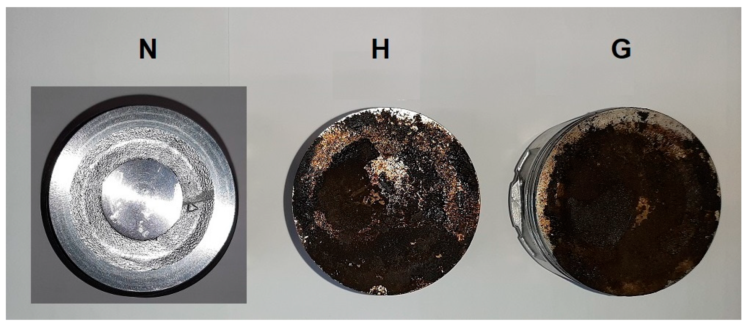
During the experiment, engines were stopped after the first 20 h and then after further 100 h to replace motor oil. Then, after second 100 h (that is, after 220 h of stand operation in total) the experiment was ended and the pistons were extracted from engines. A visual examination of the piston surfaces and the combustion chamber showed a significantly lower accumulation of combustion products when using a mixture of gasoline (E5) and Brown’s gas (Figure 3), indicating more complete combustion of fuel.

2.2. Evaluation of the Conditions in a Combustion Chamber

During the generator test bench experiments, the concentrations of CO, CO2, HC, and NOₓ in the exhaust gases, as well as their temperature, were analyzed for both gasoline and a gasoline–oxyhydrogen fuel mixture. Measurements were carried out using a standard AVL DiCom 4000 exhaust gas analyzer. The results (Table 1) showed that when operating on the gasoline–oxyhydrogen mixture, the CO2 concentration decreased by a factor of 1.11, while the HC content remained almost unchanged. In contrast, the CO and NOx concentrations increased by factors of 1.13 and 2.20, respectively, whereas the exhaust gas temperature decreased by a factor of 1.1.
The most significant change was established for NOx concentration. As is known, thermal NOx formation is highly sensitive to peak flame temperature (Zeldovich mechanism) [28,29,30,31]. Therefore, increased NOx emissions can be attributed to a higher temperature reached during fuel combustion. On the other hand, reduced exhaust gas temperature shows that average combustion chamber temperature is reduced. In the case of using oxyhydrogen gas, this can be due to enhanced cooling losses due to the high burning velocity of hydrogen and short quenching distance [32,33,34]. Hydrogen is characterized by an exceptionally high combustion speed, causing the fuel–air mixture to burn more rapidly than with conventional hydrocarbons, while the energy release shifts to earlier stages of the cycle. As a result, the temperature during the later phases of the expansion stroke is already lower. Therefore, together this can indicate that localized high-temperature zones (NOx formation) coexist with lower average chamber temperature, because local reaction rates are high, but overall chamber heat is lost rapidly to walls [33,35].
The decrease in CO2 can be attributed to the lower carbon content in hydrogen compared to conventional hydrocarbon fuels. Hydrogen combustion produces water vapor instead of CO2 [36,37]. The reduction in HC emissions indicates the more complete combustion of hydrocarbons [36,38,39], while slight increases in CO emissions may result from incomplete combustion in certain regions of the combustion chamber: hydrogen can cause flame quenching and incomplete oxidation of CO to CO2, especially under rich or stoichiometric conditions [36,39,40].
When hydrogen is used as a fuel in internal combustion engines, one of the critical issues is the increased likelihood of water (H2O) formation during combustion. This can adversely affect the durability of metallic components: both surface and internal material. In this study, the probability of higher water formation was evaluated indirectly through the analysis of lubricating oil. Water vapor formed during combustion may condense and enter the engine oil, particularly when the engine operates frequently at low temperatures or undergoes frequent start–stop cycles. Once water enters the oil, emulsification occurs—typical indicators include a milky appearance and foaming. Water accelerates lubricant oxidation, depletes antioxidant additives, and promotes the formation of acidic compounds, which may cause corrosion of metallic surfaces. Moisture contamination also reduces both the kinematic and dynamic viscosity of engine oils. A thinner oil film increases metal-to-metal contact, friction, heat generation, and mechanical wear, especially in highly loaded components such as bearings and piston rings. Consequently, a higher concentration of metallic elements in the oil may be observed, confirming intensified wear processes. To further assess changes in combustion chamber conditions, three parameters of oil were analyzed: oil appearance, chemical composition, and mass loss after drying. Shell Helix Ultra 5W-40 fully synthetic motor oil was used in the experiments.
Visual inspection of engine oils after 20, 120, and 220 h of operation with gasoline (G) and the mixture containing oxyhydrogen (H) did not reveal any signs of oil emulsification. Visually, the oil used in the gasoline engine did not differ from the oil used in the oxyhydrogen engine.
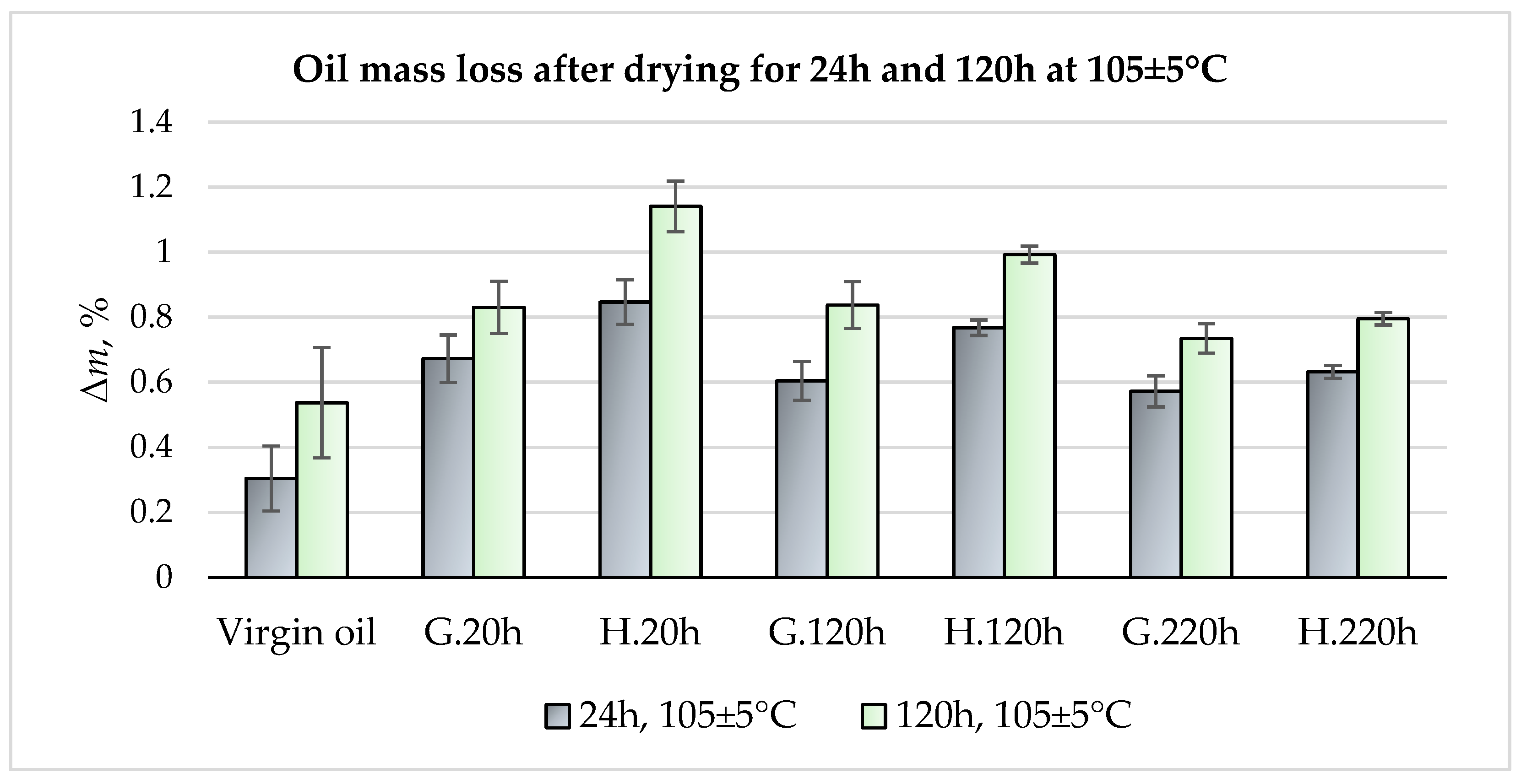
Drying tests were performed by keeping ~10 g of oil in a ceramic crucible in an electric oven at 105 ± 5 °C for 24 h and 120 h. Empty crucibles and crucibles containing oil were weighed before and after drying using a KERN PLS 360-3 analytical balance with an accuracy of 0.001 g. For each batch, three samples were dried and measured. Arithmetical means are reported together with standard deviation values, calculated as STDEVp in Excel, in Figure 4. The drying experiments showed that the mass loss of virgin oil after 24 h at 105 ± 5 °C was ~0.30%. Prolonged drying (120 h) increased the loss to ~0.54%. In contrast, oils taken from engines after first 20 h exhibited significantly higher mass losses: ~1.6–2.2 times greater after gasoline operation and ~2.1–2.8 times greater after hydrogen operation compared with unused oil. Thus, when hydrogen was used as fuel, oil mass loss increased by ~26–37% relative to gasoline. After 120 h of drying, these trends remained consistent. For oil samples extracted after 220 h of engine operation, the difference between G and H was not so significant, but the trend remained. These findings confirmed that the use of oxyhydrogen gas resulted in greater moisture saturation of the oil.
The elemental composition of the oil was analyzed using wavelength-dispersive X-ray fluorescence spectrometer ZSX Primus IV (Rigaku, Tokyo, Japan; Rh anode, 4 kW). Operating parameters were 60 kV and 150 mA. A higher sulfur concentration was observed—~39% after gasoline operation and 2.43 times greater with hydrogen (Table 2). Sulfur originates from additives, and its accumulation is attributed to oil evaporation and thermal degradation during engine operation. The higher sulfur level with hydrogen suggests elevated combustion temperatures. Traces of Al, Si, and Fe were also detected in the oil, with lower concentrations after gasoline and higher after hydrogen operation. These elements stem from wear of metallic components in contact with the lubricant. Their increased presence under hydrogen points to intensified surface degradation, likely due to combined effects of moisture saturation, higher combustion temperature, and resulting changes in oil properties and frictional conditions.
The analysis of exhaust gases, combined with engine oil testing, indicated that the use of a gasoline–oxyhydrogen mixture resulted in localized increases in combustion chamber temperatures and higher moisture content in the engine oil. To evaluate the effect of these altered operating conditions on the mechanical properties of the aluminum alloy components, mechanical testing and microstructural analysis were performed on samples extracted from the pistons. The results are presented in Section 3.

2.3. Testing Methods

The hardness and microhardness of the alloy were determined using the Vickers indentation method on ground and polished cross sections cut perpendicularly to the piston crown surface (samples Nr. 1 and Nr. 2). Hardness was measured with a Vickers hardness tester HV-100 (Mitutoyo, Japan) under a load of 5 kgf and a duration time of 10 s. The average Vickers hardness values were calculated as the arithmetic mean of 10–12 individual measurements. The standard deviation of the average hardness was calculated using the STDEV.P function in Microsoft Excel. The microhardness of the piston alloy, as well as its depth distribution, was assessed using a microhardness tester Zwick Roell ZHµ (ZwickRoellGmbH&Co. KG, Ulm, Germany) under a load of 50 g and a duration of 15 s. To evaluate the microhardness distribution in the normal direction to the piston crown surface, measurements were conducted with a 75 μm indentation step. The average microhardness values were calculated as the arithmetic mean of 5–6 individual measurements.
The strength and plastic properties of the piston alloy were determined through static tensile and three-point bending tests. The experiments were carried out using a TIRA test 2300 testing machine (TIRA GmbH, Schalkau, Germany) equipped with a CATMAN data acquisition system. The test parameters were selected in accordance with ISO 6892-1: the loading rate in the elastic region was approximately 11.5 MPa/s, the strain gauge base length was 20 mm, and the sensitivity was 0.00001 mm [41].
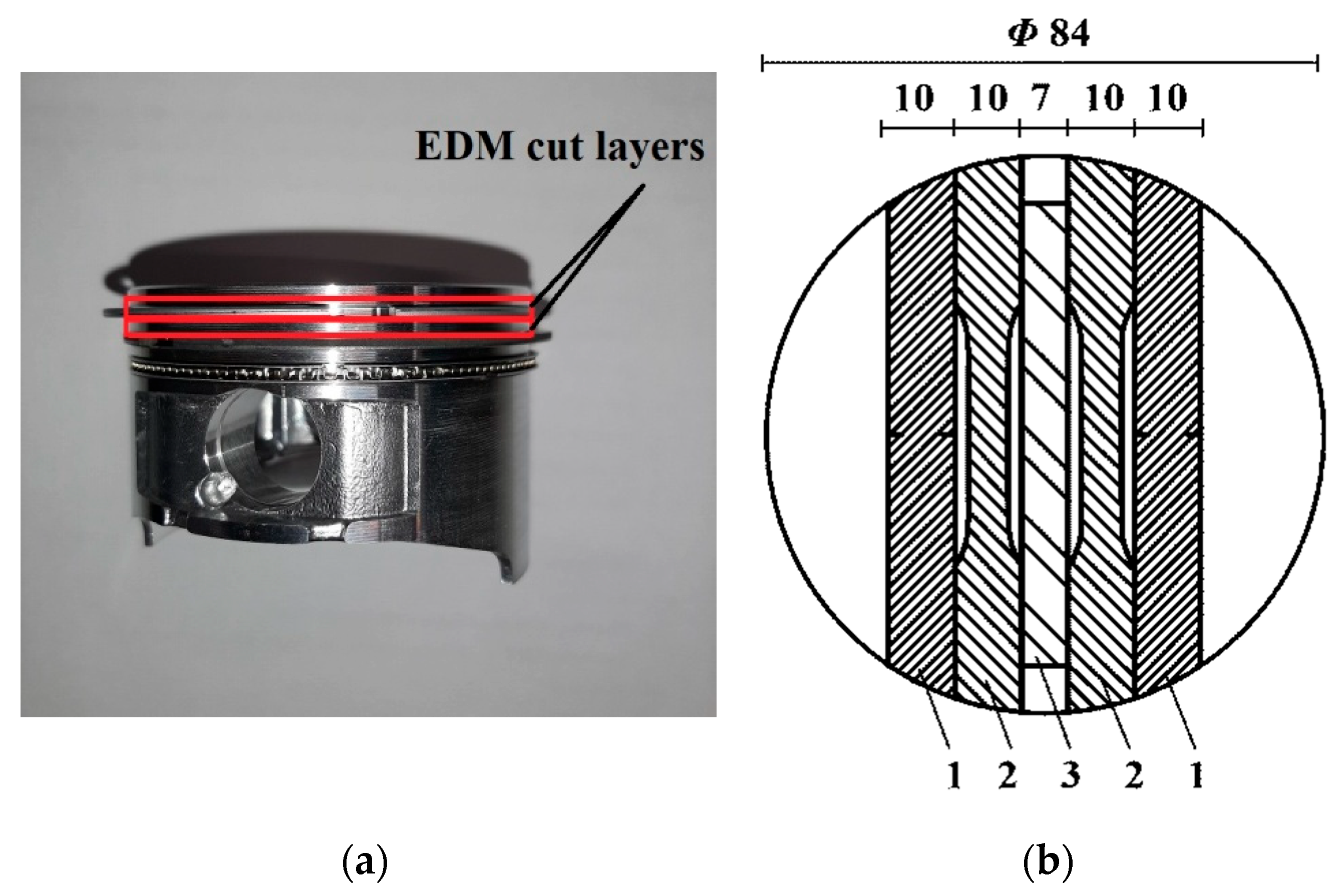
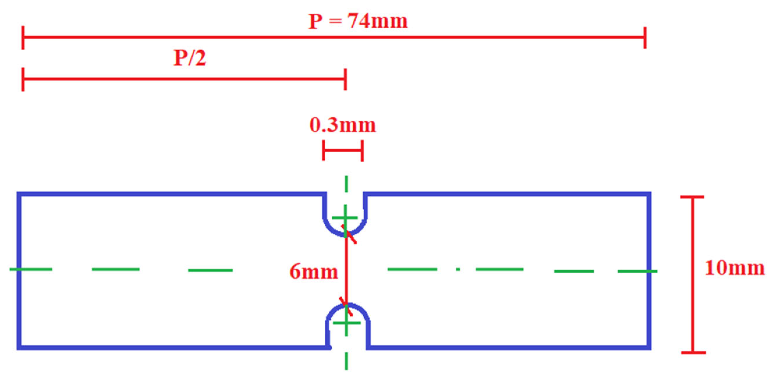
Rectangular cross-section specimens were prepared from the upper part (crown) of the pistons (new and operated), cut parallel to the crown surface of piston using an electrical discharge cutting machine (EDM) (Figure 5). At the beginning, from the upper part of the piston, two plates with a thickness of 2 mm each were cut out, and from each plate, two standard tensile specimens, two non-standard with notch specimens, and one bending specimen were prepared. During the mechanical properties tests of the piston alloy, four standard tensile specimens, four non-standard with notch specimens, and two bending specimens were cut out from each piston (N, H, G). For the static tensile tests, both standard specimens (in accordance with DIN 50125:2016) and non-standard rectangular specimens were used. Non-standard tensile test specimens were modified with notches in order to assess the material’s behavior under localized stress concentration (Figure 6). Such specimens are often used to analyze aspects of brittleness, crack initiation, or vulnerability, which are not revealed when testing standard specimens. The initial cross-sectional area of the fracture zone was the same for both standard and non-standard type specimens, measuring 12 mm2. For the three-point bending tests, rectangular specimens (70 × 10 × 2 mm) were used. The loading rate was approximately 0.012 mm/s, the gap between the support was 30 mm, the loading support radius was less than 1 mm, and the loading nose radius was 2 mm.
To verify the statistical significance in differences in strength, t -tests of non-equal variance for unpaired samples of the statistical hypotheses were performed: H 0 : μ i = μ j against H 1 : μ i > μ j , where i , j { N , G , H } , j i , μ i and μ j stand for the means of the samples’ corresponding properties without and with additives, respectively. The null hypothesis H 0 is rejected when p -value p > 0.05 is less than the level of significance 0.05 . The statistical analysis showed that the following alternatives were accepted: μ N > μ G , μ N > μ H , μ G > μ H , and μ H > μ H c . μ N c = μ G c was accepted and μ N c > μ G c rejected ( p = 0.4669 ). It should be noted also that the p -values for H 0 : μ i = μ j against H 1 : μ i > μ j when i , j { N , G , H } , j i were much smaller in comparison to the p -values of H 0 : μ i = μ j against H 1 : μ i > μ j when i , j { N c , G c , H c } , j i . Since for the majority cases, H 0 was rejected and the alternative H 1 accepted and the obtained p -values of the t -tests were much less than the significance level of 0.05, we can conclude that the additive decreases the strength of the aluminium and the difference is statistically significant.
A field-emission scanning electron microscope (SEM) Quattro S (ThermoFisher Scientific, Brno, Czech Republic) equipped with an EDS UltraDry 129 eV 30 energy-dispersive spectrometer was used for microstructural study of samples and X-ray micro-analysis of phases. SEM/EDS analysis was performed on cross sections after polishing and after etching using secondary (ETD detector) and backscattered (CBS detector) electron signals. Samples for analysis were cut from the same area of the piston crown for all the studied pistons. The following notation is used in this paper: samples “G”—cut from the piston, which was operated using gasoline as fuel; samples “H”—cut from the piston operated using a mixture of gasoline and oxyhydrogen (Brown’s) gas. As a reference, the samples cut from the virgin (new unused) piston and marked “N” were used. Keller’s etchant was used for etching.
Phase composition of piston crown surface was investigated by X-ray diffraction analysis using a Dron-7 diffractometer equipped with a copper anode and a nickel filter. The anode voltage was 30 kV, anode current 15 mA, scanning step 0.02°, exposure duration per step 1 s, and 2-theta interval from 25° to 80°. Two zones were analyzed, and two XRD patterns are presented in this paper for each piston. Peak identification on the XRD curve was conducted using the ICDD database.

3. Results

3.1. Analysis of Mechanical Properties

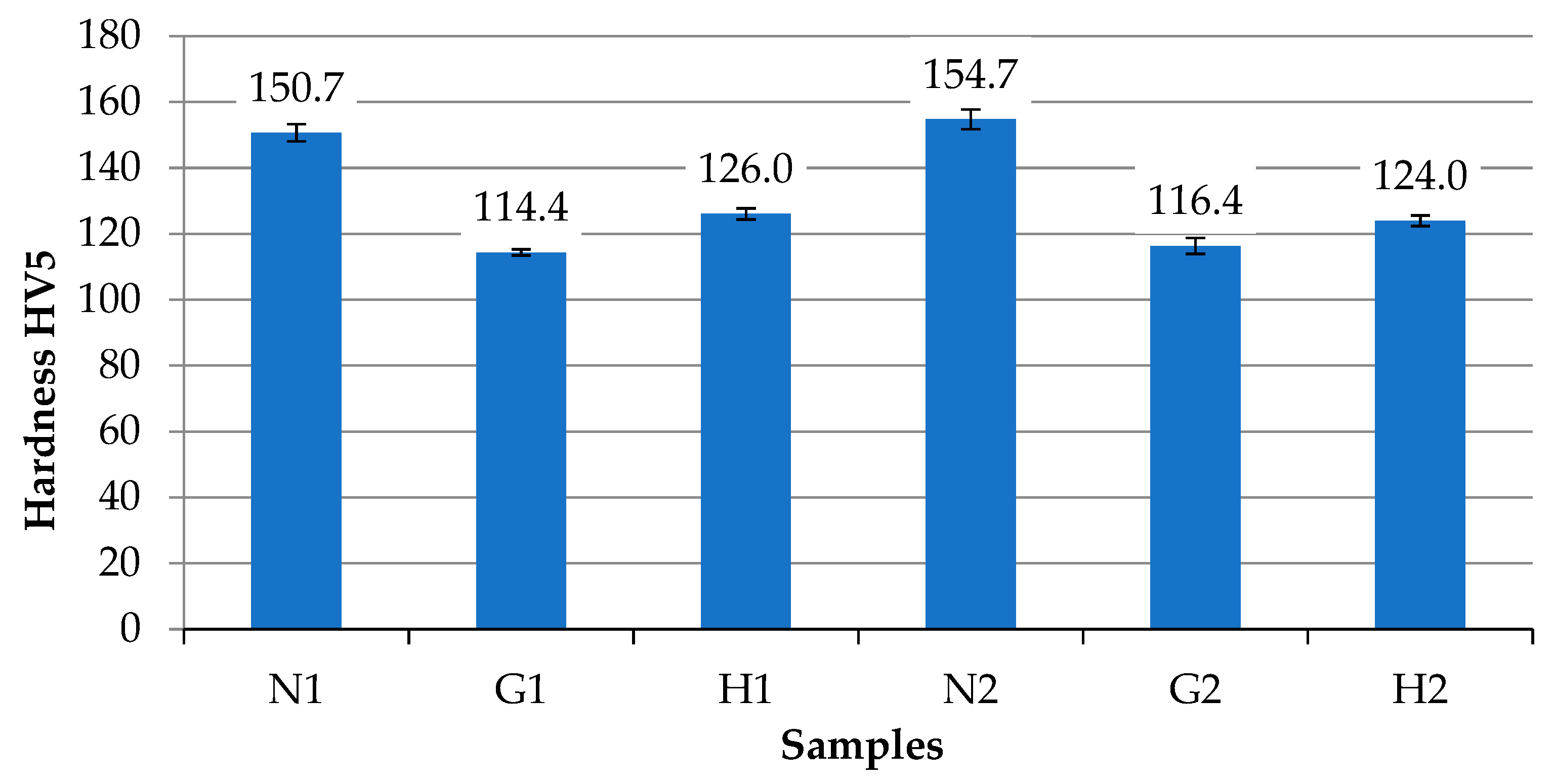
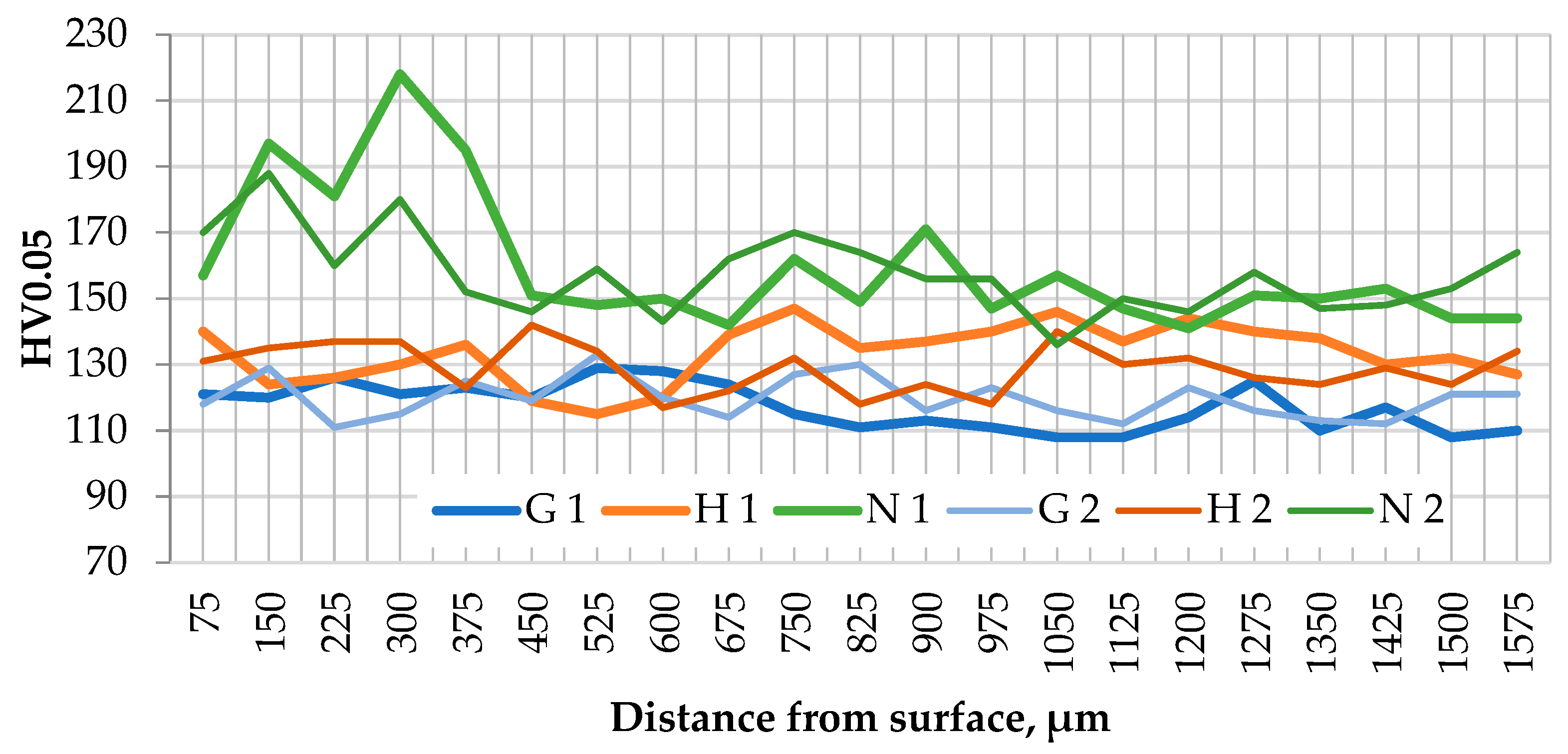
The results of the hardness and microhardness measurements (Figure 7 and Figure 8) revealed that the hardness of the piston alloy depends on the operating conditions and the type of fuel used. The hardness of the virgin piston alloy (samples N1 and N2) was the highest, with an average value of approximately 153 HV5. Operation with gasoline (samples G1 and G2) resulted in a reduction of the alloy hardness to 114–116 HV5, indicating structural changes in the metal during service time to temperature and cyclic loading effects. The samples operated with the gasoline–oxyhydrogen gas mixture (H1 and H2) exhibited a hardness about 1.2–1.3 times lower compared to the virgin samples, while in comparison with the gasoline operated pistons, their hardness values were slightly higher.
Figure 8 presents the microhardness distribution profiles of the piston alloy as a function of fuel type and operating conditions. It can be seen that the non-operated samples (N1 and N2) exhibit the highest microhardness values (up to 218 HV0.05) in the surface zone of the piston crown, which gradually decrease to 142–162 HV0.05 with increasing distance from the surface. This indicates that during piston machining processes (such as milling, etc.), the primary microstructure of the cast alloy grains in the thin surface layer was deformed, which resulted in surface layer hardening.
The G and H samples did not exhibit increased microhardness in the surface layer of the piston crown. This confirms that during their operation, the thermal cycle temperature exceeded the recrystallization temperature of the aluminum alloy (for hypereutectic aluminum alloys, 340–400 °C). The dependence of the investigated samples’ microhardness on operating conditions revealed a trend similar to that observed for alloy hardness: the operated samples exhibited up to 1.3 times lower microhardness values and no deformation-hardening zone.
During the study, static tensile tests were performed both on standard specimens (N, G, H) and on modified specimens with notches (Nc, Gc, Hc), which simulated stress concentration conditions. As shown in Figure 9, the highest tensile strength was obtained for the non-operated specimens N and Nc, reaching 283.0 MPa and 121.7 MPa, respectively. These values only slightly exceeded the tensile strength of the gasoline-operated piston specimens G and Gc. Therefore, it can be stated that operation with gasoline alone did not have a significant effect on the strength characteristics. In contrast, specimens H and Hc, operated with the gasoline–oxyhydrogen gas mixture, exhibited lower strength, which decreased by factors of 1.13 and 1.23, respectively, indicating the influence of this mixture on the mechanical properties of the material.
The use of modified specimens demonstrated that notches (stress concentrators) significantly reduced the strength of the material due to the effect of stress concentration, regardless of the operating conditions.
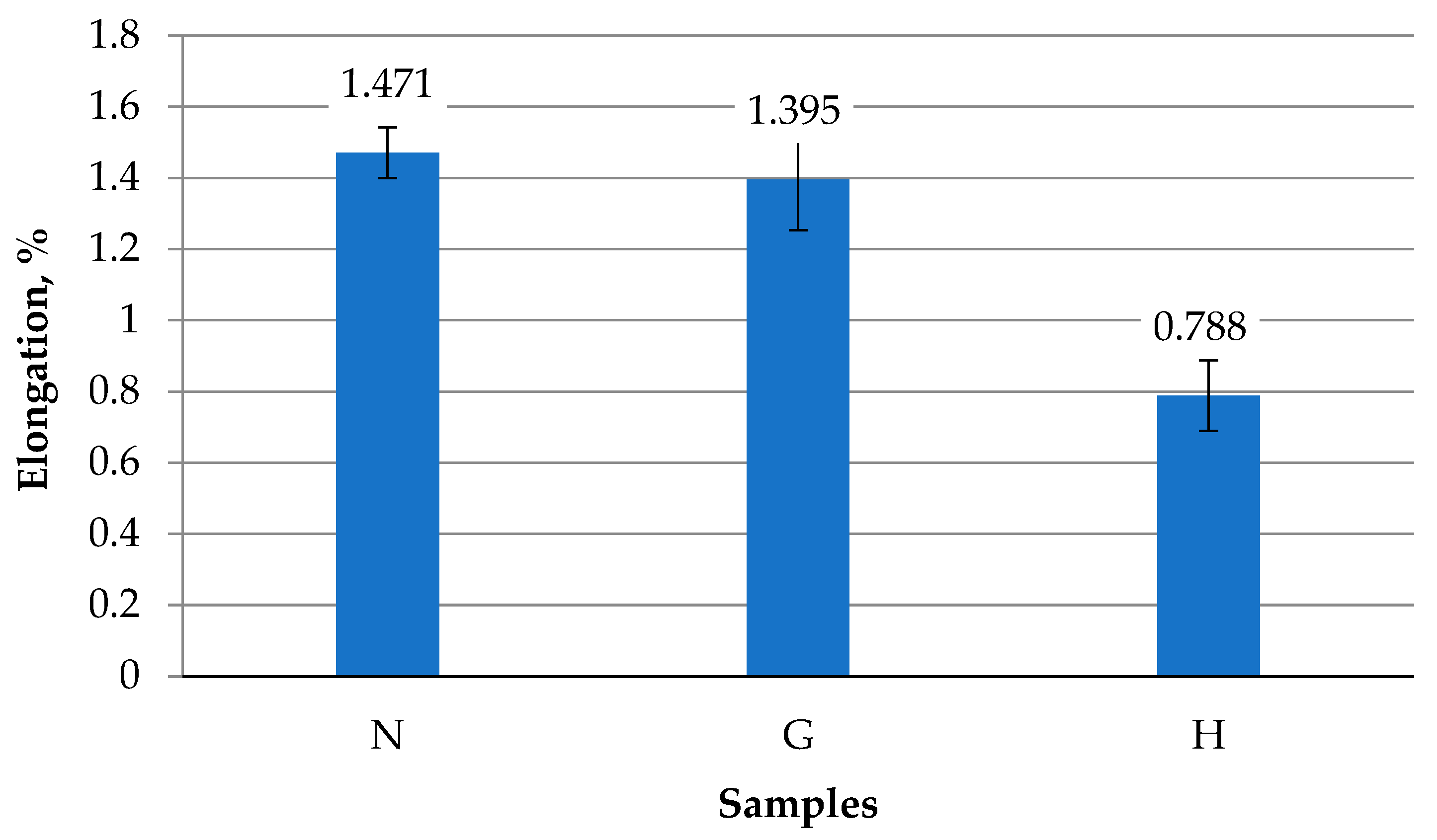
During the static tensile test, changes in the plastic properties of the piston alloy were also evaluated. As shown in Figure 10, the highest relative elongation was obtained for the non-operated specimen N, with a value of 1.471%, which is characteristic of this type of cast aluminum alloy. A very similar result (1.395%) was obtained for the specimens operated with gasoline G. This indicates that the plastic properties of the piston alloy, like its strength properties, remained practically unchanged during operation with gasoline for 220 h. The operation of specimens with the gasoline–oxyhydrogen gas mixture H significantly reduced the relative elongation of the metal—by up to 1.87 times compared to the N sample and up to 1.77 times compared to the G sample. This means that operation with a gasoline–oxyhydrogen gas mixture leads to increased brittleness of the material, which may have a negative impact on piston durability and resistance to crack formation.
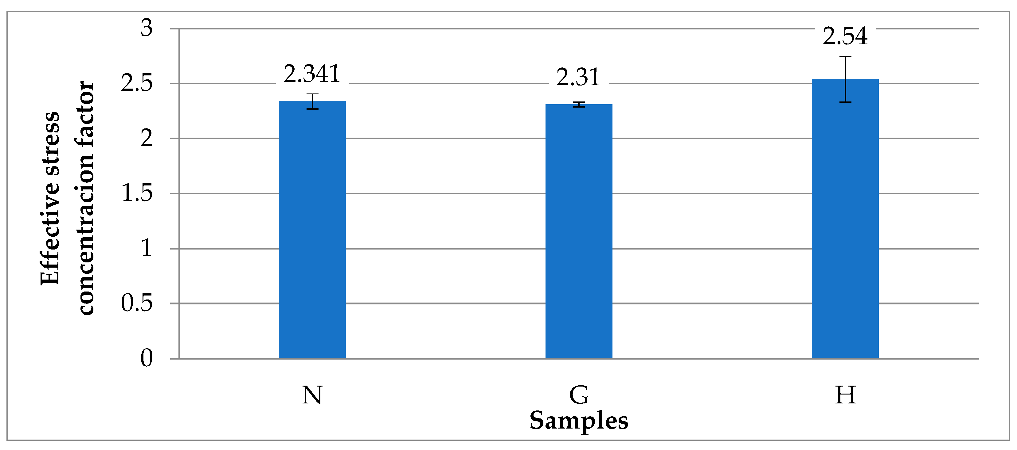
In order to evaluate the sensitivity of the investigated alloy to stress concentration, the effective stress concentration factor was calculated, defined as the ratio between the strength limits of the standard and the notched specimens. As shown in Figure 11, the sensitivity to stress concentration of the N and G specimens was identical. In contrast, piston operation with the gasoline–oxyhydrogen gas mixture increased the effective stress concentration factor values by about 1.1 times compared to the N and G specimens. Therefore, it can be stated that the oxyhydrogen admixture in the combustion process enhances the influence of stress concentrators in the piston, which may lead to accelerated initiation and growth of fatigue cracks in the metal, especially under thermal and mechanical loading cycles during operation.
The three-point bending test is one of the primary methods used to evaluate a material’s resistance to bending, its stiffness, and its brittle or plastic behavior; therefore, a bending test was carried out in this study (Figure 12).
The study revealed that piston operation with an oxyhydrogen gas admixture in the fuel mixture deteriorates the alloy’s strength properties under bending conditions: the maximum bending force decreased by approximately 1.07 times, while the maximum specimen deflection at fracture increased by about 1.59 times (Figure 13 and Figure 14). These results demonstrate that the presence of oxyhydrogen gas in the combustion process has a negative effect on the mechanical properties of the piston, reducing the stiffness of the specimens under bending loads.

3.2. Microstructural Study and Phase Analysis

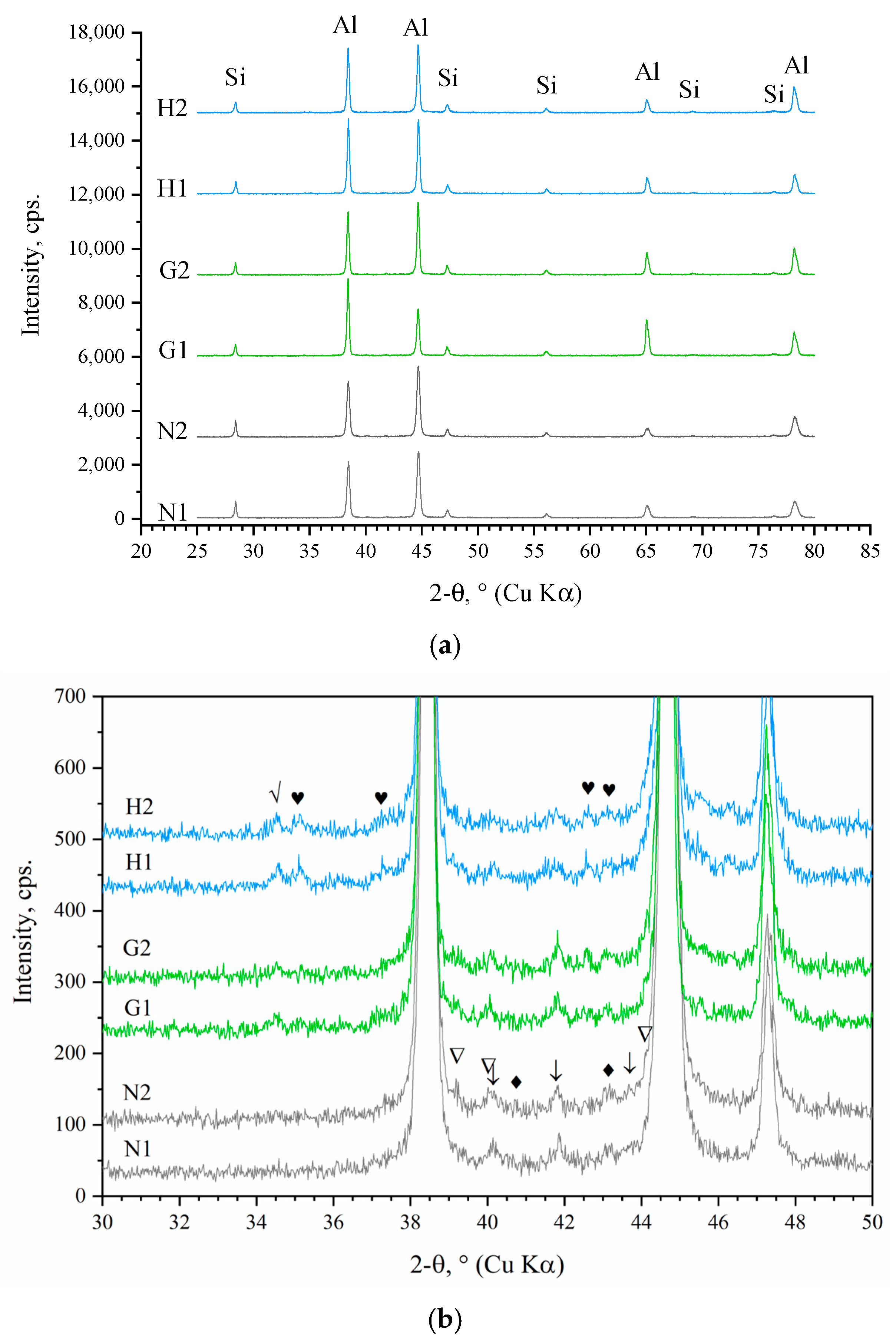
The XRD patterns of piston crown surfaces mainly revealed peaks corresponding to face-centered cubic (fcc) α-Al and metallic fcc Si (Figure 15a), which are consistent with the chemical composition of the investigated alloy and result from X-ray penetration into the deeper layers beneath the surface oxide film.
Besides major peaks, which did not reveal any differences between the surfaces of unused piston crowns and piston crowns after operation, minor peaks were observed as well (Figure 15b). The intensity of these peaks is relatively low, which makes it more difficult for identification; however, they show certain changes in the phase composition of sample surfaces. Thus, for N samples, peaks between ~39° and ~45° fit well to such compounds as Al–Si (Al2O3∙SiO2, 3Al2O3∙2SiO2) and alumina hydrates. After operation with gasoline (G1, G2), additional peaks near 2θ ≈ 34.5° and 35.1° were observed. As further SEM-EDS analysis showed, the formed surface layers of samples G and H consisted of Al, Si, O, and C. Taking this into account, these peaks were compared with the most intensive peaks of various Al–Si–O–C–H compounds, and it was found that they fit well to Al2O3∙2SiO2∙2H2O and α-Al2O3 (corundum), respectively. Hydrate formation can be attributed to the impact of water vapor produced during combustion, while α-Al2O3 is the only thermodynamically stable crystalline form of aluminum oxide, which may form at high temperatures through either the transformation of an amorphous alumina film into the crystalline state or additional surface oxidation. Under hydrogen-containing fuel operation (H1 and H2), the intensity of these peaks further increased, indicating possible higher concentrations of alumina and hydrates on the surface, caused by both greater water vapor release and elevated combustion temperatures.
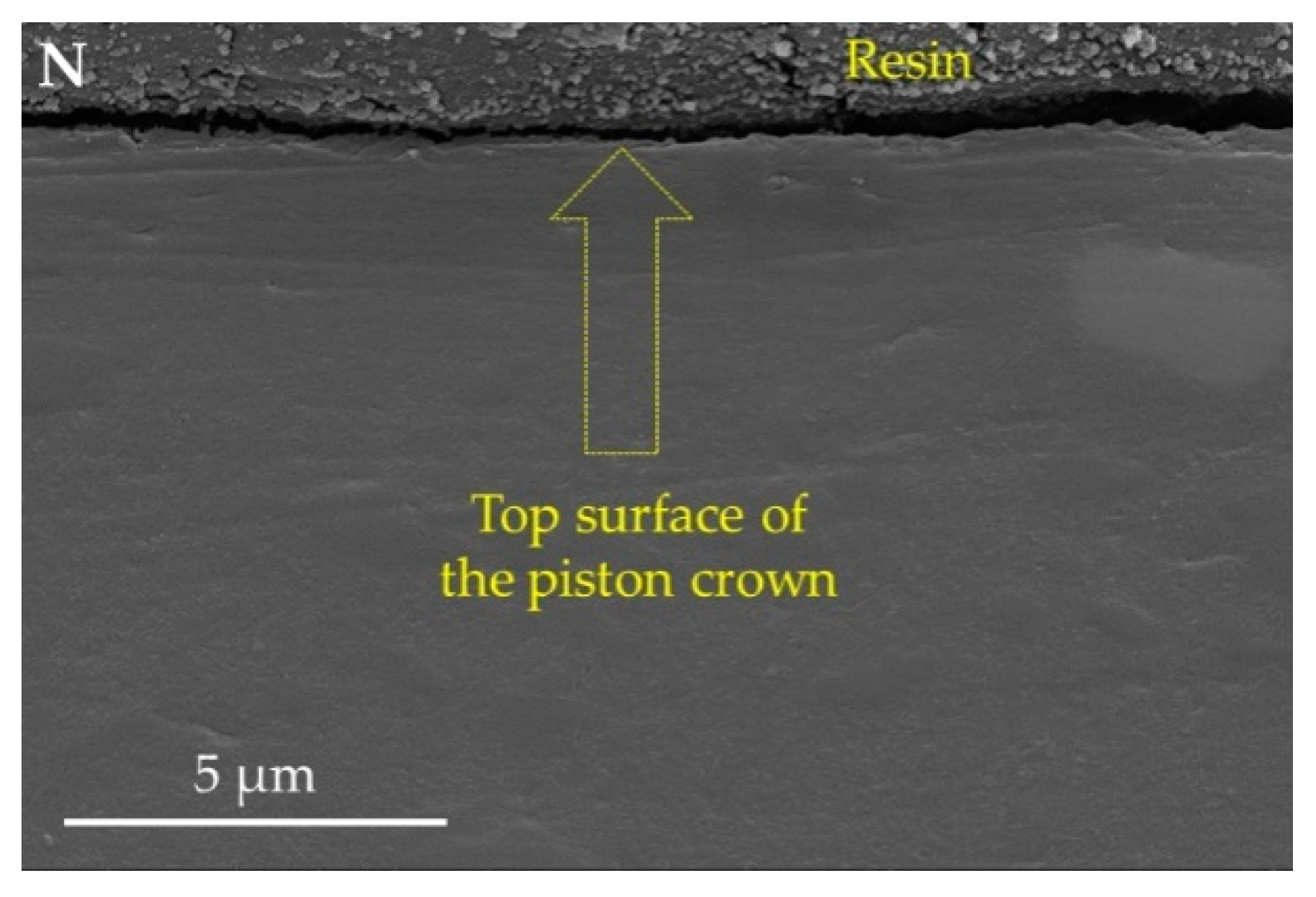
Microscopic analysis of the polished cross sections of samples revealed the presence of a very thin oxide layer at the crown top surface of the unused piston and a quite compact material structure without observable defects such as cracks, pores, or cavities near the surface (Figure 16).
The effect of hydrogen on the microstructure and properties of metals is primarily associated with the diffusion of H atoms through the metal, their accumulation—preferably in regions of stress concentration—leading to reduced cohesion and crack initiation [42,43]. Under load, this often leads to the development of cracks, which can be observed during microscopic analysis [44]. After 220 h of operation, neither the gasoline- nor the oxyhydrogen-operated pistons showed cracks or other material discontinuities (such as cavities or porosity) associated with hydrogen impact; however, both exhibited a formed surface layer clearly visible in the SEM micrographs (Figure 17a,c). Thick oxide films impede hydrogen uptake [45,46]; however, zones were observed where this layer was delaminated and fractured, indicating its brittle nature, which negatively influences the service life of the pistons (Figure 17b,d). EDS analysis revealed mainly increased concentrations of oxygen and carbon. Since hydrogen cannot be detected by EDS, EDS results in general are consistent with the results of XRD analysis and also show that carbon-containing compounds may also have formed at the surfaces during operation. Based on the 20 measurements made in different areas of sample surface, the thickness of this formed layer was 2.51 ± 0.29 µm and 3.35 ± 0.61 µm for the G and H samples, respectively, showing a tendency for this layer to be slightly thicker on the H samples. This also correlates well with the XRD results and suggests that more rapid degradation of the piston crown surface, associated with the delamination of oxidized layers, can be expected when oxyhydrogen is added to the fuel mixture.
Further SEM/EDS investigations revealed that the microstructure of the studied alloy was predominantly composed of eutectic, consisting of an aluminum matrix with inclusions of fine silicon crystals (Sieutec) and larger particles of primary silicon (Siprim) (Figure 18a). Based on the results of EDS mapping, four types of intermetallic inclusions were identified, containing various combinations of elements: Al + Cu, Al + Si + Mg + Cu, Al + Si + Mg + Fe, and Al + Si + Fe + Mn. EDS point analysis indicated compositions close to Al2Cu (the so-called θ phase), Al5Cu2Mg8Si6 (Q), Al8FeMg3Si (π), and Al15(Fe,Mn)3Si2 (α-Fe or α). These results are in good agreement with data reported by other authors on the structure of Al–Si alloys containing Cu, Mg, Fe, and Mn [20,47,48,49].
Defects are mainly represented by micropores and microcracks (generalizing as “porosity”) localized in regions enriched with intermetallic phases, which is typical for such alloys. This behavior is associated with the high hardness and limited plasticity of these phases, differences in thermal expansion coefficients, the lower crystallization temperature of possible eutectic phases, and the presence of tensile thermal stresses during cooling [50,51,52].
SEM/EDS analysis of samples G and H showed that they contained essentially the same intermetallic phases; however, more pronounced formation of intermetallics at α-Al grain boundaries was observed (Figure 18c,e). Hypereutectic Al–Si–Cu–Mg–Fe–Mn alloys represent a complex system whose structure strongly depends on the melting method, processing parameters, and subsequent thermal history, and are therefore temperature-dependent.
The presence of mainly thin films and isolated particles along the α-Al grain boundaries in sample “B” most likely indicates the initial stages of aging [53,54]. In sample “H,” more developed eutectic structures can be observed, whose formation may be indicative of a more advanced stage of service-induced aging. Moreover, visual comparison of the microstructures (Figure 18b,d,f) clearly shows that the fraction of the area occupied by intermetallic inclusions is greater in sample “H.” Quantitative assessment based on the processing of three SEM images per sample batch using Scion Image software revealed that intermetallics occupied ~3.06% ± 0.44%, 3.50% ± 0.56%, and 7.43% ± 1.65% of the cross-sectional area for the unused (N) piston and for pistons after operation with gasoline (G) and with a gasoline–oxyhydrogen mixture (H), respectively (Figure 19). Since the most critical factors influencing aging/degradation processes are duration and temperature regime and given that the exposure time during testing was identical, it can be reasonably assumed that the cause of these structural changes in the case of “H” was higher temperature.
One can also see that the precipitated intermetallic phases formed a dual-scale net-like structure: at the microscale, they surround the α-Al grains, while at the mesoscale, the Al–Si eutectic islands are surrounded by a “network” of α-Al grains with intermetallics precipitated along their boundaries (Figure 18f). Since intermetallics possess limited plasticity, such a dual-scale network acts as a brittle matrix, weakening the cohesion both between the aluminum grains and between the Al–Si islands and restricting the overall plastic deformation of material. This in turn can explain the deterioration in plasticity and toughness observed in sample H.
The results of the conducted microstructural investigations indicate that the piston materials G and H underwent processes of so-called service-induced aging caused by thermal exposure. Microhardness measurements revealed reduced values for both G and H samples compared to the unused reference sample, confirming structural changes. As studies show, the development of microhardness during aging can be complex and is determined by the combined effects of multiple processes. Short-term thermal exposure can increase hardness and strength due to precipitate formation, phase rearrangement, and spheroidization [55,56,57], whereas prolonged thermal exposure inevitably leads to property degradation [56,58,59]. Despite this, the difference between G and H was not significant—approximately 115 HV versus 125 HV, respectively. The oxyhydrogen-operated sample (H) exhibited visibly reduced strength, ductility, and toughness. The results of this preliminary study suggest that this was mainly attributable to microstructural factors such as the formation of a dual-scale brittle matrix due to formation of local high-temperature zones in a combustion chamber when oxyhydrogen gas was added to gasoline fuel. Further investigations are needed to verify whether hydrogen uptake took place and contributed to embrittlement in addition to the factor of thermal exposure.

4. Conclusions

In this work, a preliminary study was carried out to determine whether changes in the conditions inside the combustion chamber caused by the addition of a hydrogen-containing gas (in this case, Brown’s gas) can induce noticeable alterations in the structure and properties of hypereutectic aluminum alloys intended for use in internal combustion engines. The results obtained show the following.
-
The mechanical properties of the internal combustion engine piston alloy are strongly dependent on operating conditions and fuel type. Operation with gasoline alone for 220 h did not significantly affect hardness, tensile strength, stiffness, or ductility, and the alloy’s sensitivity to stress concentrators remains similar to the virgin material. In contrast, operation with a gasoline–oxyhydrogen mixture led to deterioration of mechanical properties: tensile strength decreased by 1.12–1.22 times, elongation at fracture by up to 1.77 times, and maximum bending force by 1.07 times, while maximum deflection at fracture increased by 1.59 times, indicating reduced bending resistance and stiffness.
-
Exhaust gas monitoring revealed that oxyhydrogen addition lowered the average combustion chamber temperature, but induced local temperature spikes, accelerating operational aging. This was manifested as intermetallic precipitation along α-A grain boundaries and formation of a dual-scale net-like structure, which acted as a brittle matrix, weakening cohesion between aluminum grains and Al–Si islands and restricting overall plastic deformation. The increased temperature and humidity in the chamber due to oxyhydrogen addition also accelerated the degradation of the piston crown surface.
This preliminary study demonstrates that even a small addition of Brown’s gas can lead to measurable degradation of the surface, structure, and properties of hypereutectic Al-based alloys after relatively short operation (220 h), with elevated combustion temperatures playing a key role. The findings highlight the critical importance of investigating degradation kinetics under different fueling and loading conditions. Further research is also needed to assess potential direct effects of hydrogen, particularly on steel components more susceptible to hydrogen embrittlement. Medium- and long-term engine tests with hydrogen-enriched mixtures will be essential for accurately evaluating the durability of components in hydrogen-assisted fuel systems.

Author Contributions

Conceptualization, S.P., J.Š., and O.Č.; methodology, O.Č.; formal analysis, S.P., J.Š., and R.Č.; investigation, J.Š. and O.Č.; resources, S.P.; writing—original draft preparation, J.Š., O.Č., and R.Č.; writing—review and editing, O.Č. and J.Š.; supervision, O.Č.; funding acquisition, S.P. All authors have read and agreed to the published version of the manuscript.

Funding

This research was conducted as part of the execution of the project “Mission-driven Implementation of Science and Innovation Programmes” (02-002-P-0001), funded by the Economic Revitalization and Resilience Enhancement Plan “New Generation Lithuania”.

Data Availability Statement

Data are contained within the article.

Conflicts of Interest

The authors declare no conflicts of interest.

Abbreviations

The following abbreviations are used in this manuscript.
Nunused piston
Gpiston operated with gasoline
Hpiston operated with a mixture of gasoline and oxyhydrogen
ICEinternal combustion engine
SEMscanning electron microscopy
EDSenergy-dispersive spectroscopy

References

  1. Harfoot, M.B.J.; Tittensor, D.P.; Knight, S.; Arnell, A.P.; Blyth, S.; Brooks, S.; Butchart, S.H.M.; Hutton, J.; Jones, M.I.; Kapos, V.; et al. Present and Future Biodiversity Risks from Fossil Fuel Exploitation. Conserv. Lett. 2018, 11, e12448. [Google Scholar] [CrossRef]
  2. Gattuso, J.-P.; Magnan, A.K.; Bopp, L.; Cheung, W.W.L.; Duarte, C.M.; Hinkel, J.; Mcleod, E.; Micheli, F.; Oschlies, A.; Williamson, P.; et al. Ocean Solutions to Address Climate Change and Its Effects on Marine Ecosystems. Front. Mar. Sci. 2018, 5, 337. [Google Scholar] [CrossRef]
  3. Campagne, C.S.; Roy, L.-A.; Langridge, J.; Claudet, J.; Mongruel, R.; Beillouin, D.; Thiébaut, É. Existing Evidence on the Impact of Changes in Marine Ecosystem Structure and Functioning on Ecosystem Service Delivery: A Systematic Map. Environ. Evid. 2023, 13, 1–29. [Google Scholar] [CrossRef]
  4. Roslan, S.B.; Konovessis, D.; Tay, Z.Y. Sustainable Hybrid Marine Power Systems for Power Management Optimisation: A Review. Energies 2022, 15, 29622. [Google Scholar] [CrossRef]
  5. Radica, G.; Vidović, T.; Šimunović, J.; Jurić, Z. Overview of Hybrid Marine Energy System Configurations and System Component Modelling Approaches. Energies 2025, 18, 1189. [Google Scholar] [CrossRef]
  6. Foretich, A.; Zaimes, G.G.; Hawkins, T.R.; Newes, E. Challenges and Opportunities for Alternative Fuels in the Maritime Sector. Marit. Transp. Res. 2021, 2, 100033. [Google Scholar] [CrossRef]
  7. Verhelst, S.; Wallner, T. Hydrogen-Fueled Internal Combustion Engines. Prog. Energy Combust. Sci. 2009, 35, 490–527. [Google Scholar] [CrossRef]
  8. Ihsan Shahid, M.; Rao, A.; Farhan, M.; Liu, Y.; Ahmad Salam, H.; Chen, T.; Ma, F. Hydrogen Production Techniques and Use of Hydrogen in Internal Combustion Engine: A Comprehensive Review. Fuel 2024, 378, 132769. [Google Scholar] [CrossRef]
  9. Shadidi, B.; Najafi, G.; Yusaf, T. A Review of Hydrogen as a Fuel in Internal Combustion Engines. Energies 2021, 14, 6209. [Google Scholar] [CrossRef]
  10. Turner, J.W.G. Future Technological Directions for Hydrogen Internal Combustion Engines in Transport Applications. Appl. Energy Combust. Sci. 2025, 21, 100302. [Google Scholar] [CrossRef]
  11. Goyal, H.; Jones, P.; Bajwa, A.; Parsons, D.; Akehurst, S.; Davy, M.H.; Leach, F.C.; Esposito, S. Design Trends and Challenges in Hydrogen Direct Injection (H2DI) Internal Combustion Engines—A Review. Int. J. Hydrogen Energy 2024, 86, 1179–1194. [Google Scholar] [CrossRef]
  12. Rimkus, A.; Žaglinskis, J. Study of the Combustion Characteristics of a Compression Ignition Engine Fueled with a Biogas–Hydrogen Mixture and Biodiesel. J. Mar. Sci. Eng. 2024, 12, 2192. [Google Scholar] [CrossRef]
  13. Włodarczyk, P.P.; Włodarczyk, B. Deterioration of Property of Aluminum Alloys (EN AW-1050A, EN AW-5754 and EN AW-6060) by Absorbed Hydrogen. Appl. Sci. 2022, 12, 1392. [Google Scholar] [CrossRef]
  14. Papantoniou, I.G.; Karmiris-Obratański, P.; Leszczyńska-Madej, B.; Manolakos, D.E. Investigating the Impact of Friction Stir Processing on the Hydrogen Embrittlement in AA6082-T6 Heat-Treatable Aluminum Alloy. Met. Mater. Int. 2024, 30, 2668–2684. [Google Scholar] [CrossRef]
  15. Shin, D.-H.; Kim, S.-J. Effects of Hard Anodizing and Plasma Ion-Nitriding on Al Alloy for Hydrogen Embrittlement Portection. Corros. Sci. Technol. 2023, 22, 221–231. [Google Scholar] [CrossRef]
  16. Havazadeh, M.; Raeissi, K. The Effect of Hydrogen on Mechanical Properties of 7075-T6 Al at Elevated Temperatures for High-Duty Compressor Applications. J. Mater. Eng. Perform. 2025, 1–9. [Google Scholar] [CrossRef]
  17. Li, H.; Yang, Z.; Zhang, C.; Peng, W.; Ma, K.; Oleksandr, M. Effects of hydrogen on the dynamic mechanical properties and microstructure of 7055 and 7A52 aluminum alloys. Mater. Charact. 2023, 203, 113151. [Google Scholar] [CrossRef]
  18. Gong, C.; Tu, H.; Wu, C.; Wang, J.; Su, X. Study on Microstructure and Mechanical Properties of Hypereutectic Al–18Si Alloy Modified with Al–3B. Materials 2018, 11, 456. [Google Scholar] [CrossRef]
  19. Xia, F.; Dong, X.; Wang, J.; Duan, H.; Ma, Z.; Liang, M. Microstructural Evolution and Tensile Properties of Al-Si Piston Alloys during Long-Term Thermal Exposure. Metals 2024, 14, 535. [Google Scholar] [CrossRef]
  20. Lin, B.; Li, H.; Xu, R.; Zhao, Y.; Xiao, H.; Tang, Z.; Li, S. Thermal exposure of Al-Si-Cu-Mn-Fe alloys and its contribution to high temperature mechanical properties. J. Mater. Res. Technol. 2020, 9, 1856–1865. [Google Scholar] [CrossRef]
  21. Liu, Y.; Bian, Z.; Chen, Z.; Wang, M.; Chen, D.; Wang, H. Effect of Mn on the elevated temperature mechanical properties of Al-La alloys. Mater. Character. 2019, 155, 109821. [Google Scholar] [CrossRef]
  22. Chen, F.; Liu, C.; Zuo, L.; Wu, Z.; He, Y.; Dong, K.; Li, G.; He, W. Effect of Thermal Exposure on Mechanical Properties of Al-Si-Cu-Ni-Mg Aluminum Alloy. Crystals 2023, 13, 236. [Google Scholar] [CrossRef]
  23. Zhang, M.; Tian, Y.; Zheng, X.; Zhang, Y.; Chen, L.; Wang, J. Research Progress on Multi-Component Alloying and Heat Treatment of High Strength and Toughness Al–Si–Cu–Mg Cast Aluminum Alloys. Materials 2023, 16, 1065. [Google Scholar] [CrossRef]
  24. Liu, H.; Zeng, Z.-X.; Guo, K.-F. Effect of Equivalence Ratio on H2/Air Combustion Characteristics of Micro Gas Turbine. J. Eng. Therm. Energy Power 2022, 37, 72–78. [Google Scholar] [CrossRef]
  25. Wang, S.; Ji, C.; Zhang, B.; Zhou, X. Analysis on combustion of a hydrogen-blended gasoline engine at high loads and lean conditions. Energy Procedia 2014, 61, 323–326. [Google Scholar] [CrossRef]
  26. Romański, L. Wodór Nośnikiem Energii; Wydawnictwo Uniwersytetu Przyrodniczego: Wrocław, Poland, 2007; ISBN 978-83-60574-12-6. [Google Scholar]
  27. Henkensmeier, D.; Cho, W.-C.; Jannasch, P.; Stojadinovic, J.; Li, Q.; Aili, D.; Jensen, J.O. Separators and Membranes for Advanced Alkaline Water Electrolysis. Chem. Rev. 2024, 124, 6393–6443. [Google Scholar] [CrossRef]
  28. Hodzic, N.; Kazagic, A.; Kadic, K. Qualitative Analysis of the Structure of NOx Emissions during Combustion of Pulverized Coal and Biomass and Staged Air Supply Conditions in Furnace. In New Technologies, Development and Application VI; Lecture Notes in Networks and Systems; Springer: Cham, Switzerland, 2023; Volume 707. [Google Scholar] [CrossRef]
  29. Studzinski, W.M.; Liiva, P.M.; Choate, P.J.; Brezinsky, K. A Computational and Experimental Study of Combustion Chamber Deposit Effects on NOx Emissions; SAE Technical Paper; SAE International: Warrendale, PA, USA, 1993. [Google Scholar] [CrossRef]
  30. Ma, T.; Feng, W.; Sun, X.; Jing, G. Numerical Study of NOx Formation Mechanism in Ammonia-Hydrogen Compound Fuel Marine Engines under Varying Conditions. Int. J. Hydrogen Energy 2024, 19, 1422–1434. [Google Scholar] [CrossRef]
  31. Pan, P.; Wen, Y.; Su, Z.; Li, Z. Effects of Temperature, Reducing Agent Concentration and Water Vapor on NO Emission of Hydrogen Fuel Engines Using NOx Storage and Reduction Technology. J. Xi’an Jiaotong Univ. 2023, 57, 82–90. [Google Scholar] [CrossRef]
  32. Shudo, T.; Oka, H. Thermophysical Properties of Working Fluid and Heat Transfer in a Hydrogen Combustion Engine. Trans. Jpn. Soc. Mech. Eng. B 2005, 71, 730–736. [Google Scholar] [CrossRef]
  33. Shudo, T.; Nabetani, S. Analysis of Degree of Constant Volume and Cooling Loss in a Hydrogen Fuelled SI Engine; SAE Technical Paper; SAE International: Warrendale, PA, USA, 2001. [Google Scholar] [CrossRef]
  34. Shudo, T.; Nabetani, S.; Nakajima, Y. Analysis of the Degree of Constant Volume and Cooling Loss in a Spark Ignition Engine Fuelled with Hydrogen. Int. J. Engine Res. 2001, 2, 81–92. [Google Scholar] [CrossRef]
  35. Younkins, M.; Wooldridge, M.S.; Boyer, B.A. Port Injection of Water into a Di Hydrogen Engine; SAE Technical Paper; SAE International: Warrendale, PA, USA, 2015. [Google Scholar] [CrossRef]
  36. Choi, G.H.; Han, S.B. Performance and Exhaust Emissions Test Results from a Liquid Propane Injected Engine with Hydrogen Enrichment. Proc. Inst. Mech. Eng. Part D J. Automob. Eng. 2004, 218, 1135–1140. [Google Scholar] [CrossRef]
  37. Huang, Q.; Miao, H.-Y.; Huang, Z.-H.; Jiang, D.-M.; Zeng, K. Effects of CO2 from EGR on Laminar Combustion Characteristics of Hydrogen. J. Combust. Sci. Technol. 2009, 15, 361–367. [Google Scholar]
  38. Morovatiyan, M.; Shahsavan, M.; Baghirzade, M.; Mack, J.H. Effect of Hydrogen and Carbon Monoxide Addition to Methane on Laminar Burning Velocity. In Proceedings of the Internal Combustion Engine Division Fall Technical Conference, Chicago, IL, USA, 20–23 October 2019; ASME: Chicago, IL, USA, 2019; p. V001T02A006. [Google Scholar] [CrossRef]
  39. Du, Y.; Yu, X.; Liu, L.; Li, R.; Zuo, X.; Sun, Y. Effect of Addition of Hydrogen and Exhaust Gas Recirculation on Characteristics of Hydrogen Gasoline Engine. Int. J. Hydrogen Energy 2017, 42, 8288–8298. [Google Scholar] [CrossRef]
  40. Piqueras, P.; Morena, J.D.l.; Sanchis, E.J.; Pitarch, R. Impact of Exhaust Gas Recirculation on Gaseous Emissions of Turbocharged Spark-Ignition Engines. Appl. Sci. 2020, 10, 7634. [Google Scholar] [CrossRef]
  41. ISO 6892-1:2019(En); Metallic Materials—Tensile Testing—Part 1: Method of Test at Room Temperature. ISO: Geneva, Switzerland. Available online: https://www.iso.org/obp/ui/en/#iso:std:iso:6892:-1:ed-3:v1:en (accessed on 25 September 2025).
  42. Chen, Y.-S.; Huang, C.; Liu, P.-Y.; Yen, H.-W.; Niu, R.; Burr, P.; Moore, K.L.; Martínez-Pañeda, E.; Atrens, A.; Cairney, J.M. Hydrogen Trapping and Embrittlement in Metals—A Review. Int. J. Hydrogen Energy 2025, 136, 789–821. [Google Scholar] [CrossRef]
  43. Campari, A.; Ustolin, F.; Alvaro, A.; Paltrinieri, N. A Review on Hydrogen Embrittlement and Risk-Based Inspection of Hydrogen Technologies. Int. J. Hydrogen Energy 2023, 48, 35316–35346. [Google Scholar] [CrossRef]
  44. Luo, X.; Bian, B.; Zhang, K.; Tian, D.; Pan, M.; Chen, X.; Zhao, H. Investigation of Hydrogen Embrittlement in 12Cr2Mo1R(H) Steel. J. Mater. Res. 2018, 33, 3501–3511. [Google Scholar] [CrossRef]
  45. Scully, J.R.; Young, G.A.; Smith, S.W. Hydrogen Embrittlement of Aluminum and Aluminum-Based Alloys. In Gaseous Hydrogen Embrittlement of Materials in Energy Technologies; Elsevier: Amsterdam, The Netherlands, 2012. [Google Scholar] [CrossRef]
  46. Umeda, H.; Itoh, G.; Kato, Y. Hydrogen Absorption Behavior in Al-Mg Alloys Exposed to an SO2 Atmosphere During Subsequent Annealing. J. Jpn. Inst. Light Met. 2007, 57, 203–209. [Google Scholar] [CrossRef]
  47. Lasa, L.; Rodriguez-Ibabe, J.M. Evolution of the Main Intermetallic Phases in Al-Si-Cu-Mg Casting Alloys during Solution Treatment. J. Mater. Sci. 2004, 39, 1343–1355. [Google Scholar] [CrossRef]
  48. Zhu, X.; Dong, X.; Blake, P.; Ji, S. Improvement in As-Cast Strength of High Pressure Die-Cast Al–Si–Cu–Mg Alloys by Synergistic Effect of Q-Al5Cu2Mg8Si6 and θ-Al2Cu Phases. Mater. Sci. Eng. A 2021, 802, 140612. [Google Scholar] [CrossRef]
  49. Cáceres, C.H.; Djurdjevic, M.B.; Stockwell, T.J.; Sokolowski, J.H. The Effect of Cu Content on the Level of Microporosity in Al-Si-Cu-Mg Casting Alloys. Scripta Mater. 1999, 40, 631–637. [Google Scholar] [CrossRef]
  50. Tupaj, M.; Orłowicz, A.W.; Mróz, M.; Trytek, A.; Dolata, A.J.; Dziedzic, A. A Study on Material Properties of Intermetallic Phases in a Multicomponent Hypereutectic Al-Si Alloy with the Use of Nanoindentation Testing. Materials 2020, 13, 5612. [Google Scholar] [CrossRef]
  51. Mohamed, A.M.A.; Samuel, E.; Zedan, Y.; Samuel, A.M.; Doty, H.W.; Samuel, F.H. Intermetallics Formation during Solidification of Al-Si-Cu-Mg Cast Alloys. Materials 2022, 15, 1335. [Google Scholar] [CrossRef]
  52. Bogdanof, T. The Effect of Microstructural Features, Defects and Surface Quality on the Fatigue Performance in Al-Si-Mg Cast Alloys. Ph.D. Thesis, School of Engineering, Jönköping University, Jönköping, Sweden, 2023. Available online: https://www.diva-portal.org/smash/get/diva2:1813756/FULLTEXT01.pdf (accessed on 20 August 2025).
  53. Zhao, H.; De Geuser, F.; Kwiatkowski da Silva, A.; Szczepaniak, A.; Gault, B.; Ponge, D.; Raabe, D. Segregation Assisted Grain Boundary Precipitation in a Model Al-Zn-Mg-Cu Alloy. Acta Mater. 2018, 156, 318–329. [Google Scholar] [CrossRef]
  54. Foley, D.L.; Leff, A.C.; Lang, A.C.; Taheri, M.L. Evolution of β-Phase Precipitates in an Aluminum-Magnesium Alloy at the Nanoscale. Acta Mater. 2020, 185, 279–286. [Google Scholar] [CrossRef]
  55. Xia, F.; Li, J.-P.; Guo, Y.-C.; Yang, Z. Microstructure Evolution and Mechanical Properties of an Al-Si-Cu-Mg-Ni Aluminium Alloy after Thermal Exposure. Mater. Sci. Forum 2013, 765, 486–490. [Google Scholar] [CrossRef]
  56. An, M.; Wang, C.; Li, F.; Yan, R. Effects of Fe and Ni Additions and Thermal Exposure on the Microstructure and Mechanical Properties of Hypereutectic Al–Si–Cu–Mg Alloy. Int. J. Metalcast. 2025, 1–14. [Google Scholar] [CrossRef]
  57. Nagesh Kumar, R.; Prabhu, T.R.; Siddaraju, C. Effect of Thermal Exposure on Mechanical Properties Hypoeutectic Aerospace Grade Aluminium-Silicon Alloy. In IOP Conference Series: Materials Science and Engineering; IOP Publishing: Bristol, UK, 2016. [Google Scholar] [CrossRef]
  58. Fadl, M.; Khalifa, W.; El-Hadad, S. Effect of Soaking Treatment on the Microstructure and Wear Behavior of the Ultrasonic Melt-Treated B390 Hypereutectic Al-Si Alloy. TMS Light. Met. 2016, 2016, 821–825. [Google Scholar] [CrossRef]
  59. Lee, J.C.; Lee, S.; Lee, D.Y.; Kim, N.J. On the Embrittlement of a Rapidly Solidified Al-Fe-V-Si Alloy After High-Temperature Exposure. Metall. Trans. A 1991, 22, 853–858. [Google Scholar] [CrossRef]
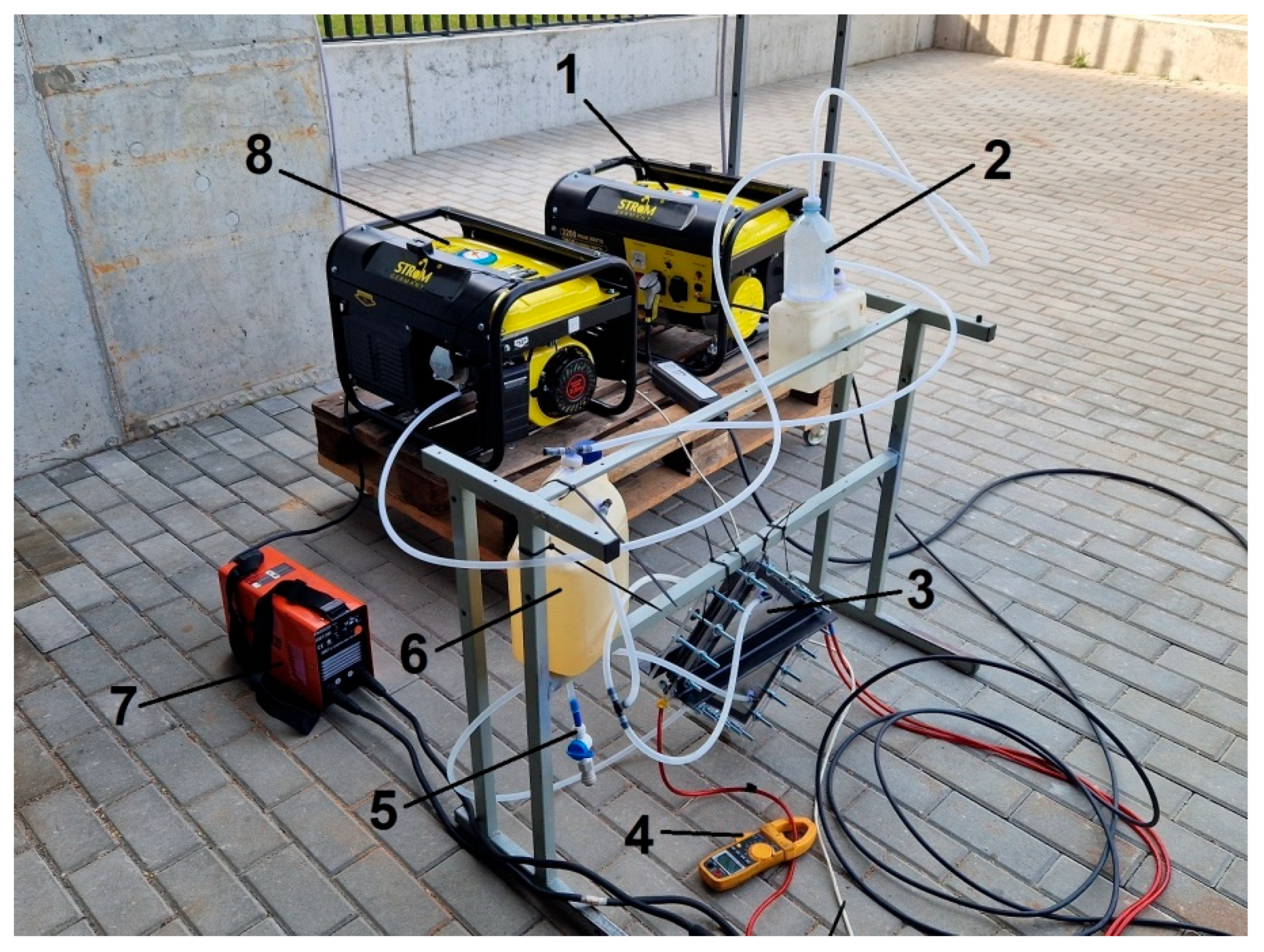
Figure 1. General view of stand: 1—engine–generator powered by gasoline; 2—HHO gas collection tank; 3—electrolyzer; 4—multimeter; 5—drain valve; 6—KOH tank (KOH = potassium hydroxide); 7—power supply; 8—engine–generator powered by a gasoline–HHO mixture.
Jmse 13 01889 g001
Figure 2. General view of the studied unused piston.
Jmse 13 01889 g002
Figure 3. General view of the studied pistons after operating for 220 h: N—virgin piston; G—operated with gasoline; H—operated with a mixture of gasoline and oxyhydrogen gas.
Jmse 13 01889 g003
Figure 4. Mass losses of oil after drying.
Jmse 13 01889 g004
Figure 5. Scheme of cutting specimens for tensile and bending tests (all sizes in mm): (a) EDM cutting scheme of piston; (b) scheme of cutting samples from the piston layer: 1—non-standard specimens modified with notches for tensile test; 2—standard specimens for tensile test; 3—specimen for bending test.
Jmse 13 01889 g005
Figure 6. Non-standard specimens modified with notches for tensile test: blue color—outline of the specimen; red color—dimensions of the specimen; green color—axis of symmetry.
Jmse 13 01889 g006
Figure 7. Hardness of pistons (samples Nr. 1 and Nr. 2) alloy: N—virgin piston; G—operated with gasoline; H—operated with a mixture of gasoline and oxyhydrogen gas.
Jmse 13 01889 g007
Figure 8. Microhardness distribution profiles in depth for piston crowns: N—virgin piston; G—operated with gasoline; H—operated with a mixture of gasoline and oxyhydrogen gas.
Jmse 13 01889 g008
Figure 9. Ultimate tensile strength of studied samples N (non-used), G (gasoline), and H (mixture of gasoline and oxyhydrogen gas): N, G, H—tests performed using standard tensile test specimens. Nc, Gc, Hc—tests performed using non-standard tensile test specimens modified with notches.
Jmse 13 01889 g009
Figure 10. Elongation of studied samples: N (non-used), G (gasoline), and H (mixture of gasoline and oxyhydrogen gas).
Jmse 13 01889 g010
Figure 11. Effective stress concentration factor of studied samples: N (non-used), G (gasoline), and H (mixture of gasoline and oxyhydrogen gas).
Jmse 13 01889 g011
Figure 12. Graph of three-point bending tests of studied samples: N (non-used), G (gasoline), and H (mixture of gasoline and oxyhydrogen gas).
Jmse 13 01889 g012
Figure 13. Maximum bending force at failure of studied samples: N (non-used), G (gasoline), and H (mixture of gasoline and oxyhydrogen gas).
Jmse 13 01889 g013
Figure 14. Maximum bending deflection at failure of studied samples: N (non-used), G (gasoline), and H (mixture of gasoline and oxyhydrogen gas).
Jmse 13 01889 g014
Figure 15. XRD patterns of surfaces of pistons crown for unused (N1 and N2) piston and pistons extracted after 220 h operation from engines using gasoline (G1 and G2) and a mixture of gasoline and oxyhydrogen gas (H1 and H2): (a) full-scale XRD patterns; (b) enlarged minor peaks. ↓—Al2O3∙SiO2; ♦—3Al2O3∙2SiO2; ∇—Al2O3∙2H2O; ♥—α-Al2O3; √—Al2O3∙2SiO2∙2H2O.
Jmse 13 01889 g015
Figure 16. SEM micrograph of the polished cross section of the sample cut from unused piston (N).
Jmse 13 01889 g016
Figure 17. SEM micrographs of the polished cross sections of the sample cut from gasoline (G) (a,b)-and mixture with oxyhydrogen (H) (c,d)-operated pistons: (a,c) changed layer at the combustion-facing surface of the pistons; (b,d) delaminated part of the changed surface layer.
Jmse 13 01889 g017
Figure 18. Microstructure (SEM; backscattered electrons) of studied samples N (non-used) (a,b), G (gasoline) (c,d), and H (mixture of gasoline and oxyhydrogen gas) (e,f). Siprim—primary silicon particle; Sieutec—eutectic silicon particles; α-Al—aluminum solid solution; α—Al15(Fe,Mn)3Si2; Q—Al5Cu2Mg8Si6; θ—Al2Cu; π—Al8FeMg3Si.
Jmse 13 01889 g018
Figure 19. Processed SEM micrographs of typical microstructures for the unused (N) piston (a) and pistons after operation with gasoline (G) (b) and a gasoline–oxyhydrogen mixture (H) (c), converted into binary images and showing black intermetallic phases for area quantification.
Jmse 13 01889 g019
Table 1. Parameters of exhaust gas.
FuelExhaust Gas Parameter
CO, %CO2, %HC, ppmNOx, ppmTemperature, °C
Gasoline (G)2.23 ± 0.0937.72 ± 0.042211 ± 1.94153 ± 2.57235 ± 3.15
Mixture of gasoline and oxyhydrogen gas (H)2.52 ± 0.0806.93 ± 0.048204 ± 1.18337 ± 6.85214 ± 3.86
Table 2. Elemental composition of oil (XRF, wt. % or ppm).
ElementVirgin OilG (100 h)H (100 h)
C8.11%7.58%8.60%
O91.9%92.4%91.4%
Mg1.16 ppm0.912 ppm1.68 ppm
Al-0.150 ppm0.719 ppm
Si-2.43 ppm3.71 ppm
P1.52 ppm1.39 ppm1.44 ppm
S3.95 ppm5.49 ppm9.60 ppm
Cl-0.436 ppm0.252 ppm
Ca4.05 ppm3.92 ppm3.90 ppm
Fe-0.0813 ppm0.195 ppm
Zn1.67 ppm1.44 ppm1.38 ppm
Mo0.113 ppm0.0924 ppm0.0833 ppm
Disclaimer/Publisher’s Note: The statements, opinions and data contained in all publications are solely those of the individual author(s) and contributor(s) and not of MDPI and/or the editor(s). MDPI and/or the editor(s) disclaim responsibility for any injury to people or property resulting from any ideas, methods, instructions or products referred to in the content.