Article

Optimizing AUV Navigation Using Factor Graphs with Side-Scan Sonar Integration

College of Intelligent Systems Science and Engineering, Harbin Engineering University, Harbin 150001, China
*
Author to whom correspondence should be addressed.
J. Mar. Sci. Eng. 2024, 12(2), 313; https://doi.org/10.3390/jmse12020313
Submission received: 5 January 2024 / Revised: 8 February 2024 / Accepted: 8 February 2024 / Published: 10 February 2024
(This article belongs to the Special Issue Motion Control and Path Planning of Marine Vehicles—2nd Edition)

Abstract

:
For seabed mapping, the prevalence of autonomous underwater vehicles (AUVs) employing side-scan sonar (SSS) necessitates robust navigation solutions. However, the positioning errors of traditional strapdown inertial navigation system (SINS) and Doppler velocity log (DVL) systems accumulated significantly, further exacerbated by DVL’s susceptibility to failure in complex underwater conditions. This research proposes an integrated navigation approach that utilizes factor graph optimization (FGO) along with an improved pre-integration technique integrating SSS-derived position measurements. Firstly, the reliability of SSS image registration in the presence of strong noise and feature-poor environments is improved by replacing the feature-based methods with a Fourier-based method. Moreover, the high-precision inertial measurement unit (IMU) pre-integration method could correct the heading errors of SINS significantly by considering the Earth’s rotation. Finally, the AUV’s marine experimental results demonstrated that the proposed integration method not only offers improved SSS image registration and corrects initial heading discrepancies but also delivers greater system stability, particularly in instances of DVL data loss.

1. Introduction

Seabed mapping is crucial for the high-speed and safe development of the ocean. Currently, the side-scan sonar (SSS) carried by autonomous underwater vehicles (AUVs) is widely used for seafloor mapping. However, the position information of mapping images is typically determined by the navigation system of AUVs, which is a dead reckoning (DR) navigation system by integrating an inertial navigation system (INS) and a Doppler velocity log (DVL), the navigation errors would accumulate in the system and challenge the reliability of mission execution when external position measurements are lacking. Therefore, applying the measurements of the SSS as position updates to assist the AUV’s integrated navigation clearly benefits the AUV’s mapping tasks. Similar approaches can also be applied to other seafloor mapping tasks with overlapping routes.
The integration of the strapdown INS (SINS) and the DVL constitutes the predominant method for AUVs or remote-operated vehicle (ROV) navigation [1,2]. The SINS supports attitude determination while the DVL provides body-frame-fixed velocity measurements; by integrating the attitude-refined velocity, the position can be updated. This navigation method is also referred to as dead-reckoning (DR) navigation.
The commonly adopted data fusion algorithms are based on nonlinear filtering methods to process the nonlinear state model of SINS, including the extended Kalman filter (EKF), particle filter (PF), and unscented Kalman filter (UKF) [3].
The DVL’s measurement, however, may produce outliers and invalid measurements, significantly influencing the accuracy and stability of navigation. Researchers introduced the robust Kalman filter that uses a Student-T distribution to replace the classical Gaussian distribution [4,5], reducing the influence of measurement outliers. The tightly-coupled algorithm is also proposed to reduce the influences of velocity measurement failure [6,7]. However, these methods cannot address the challenge of long-term invalid DVL measurements, which may occur when the distance between the AUV and the seafloor is long or if the DVL is not directed straight toward the seafloor. In addition, the position of DR navigation would also drift over time when the absolute position measurements are absent, such as the ultra-short baseline (USBL) system [8,9].
Fortunately, a good solution is to introduce external measurements, which both constraint position drift and reduce the influence of invalid DVL measurements. In recent years, image processing and simultaneous localization and mapping (SLAM) technology have seen widespread application in the field of navigation, including underwater sonar images. The most commonly used sonar system in AUVs is the SSS [10], which can scan the seafloor and generate acoustic images. When the AUV zigzags, the acoustic image will overlap in the same region; thus, the same object will be observed by the SSS in different positions of the AUV. Therefore, position constraint measurements can be obtained from the SSS acoustic image pairs.
Integrating the SSS measurement brings two new challenges. The first challenge pertains to the feature-based nature of existing SSS image registration methods, which are prone to failure due to acoustic noise. The existing acoustic image-aided navigation uses feature-based registration methods, which require complex terrains to provide feature points [11,12]. However, the seabed generally lacks complex terrains, which often results in the easy failure of feature-based registration methods. Therefore, the application of acoustic image-aided underwater navigation was greatly restricted. The second challenge is that the existing factor graph optimization (FGO) method usually ignores the influence of Earth’s rotation. This limitation prevents the FGO from using the Earth’s rotation to correct attitude, ultimately leading to heading errors and distorted trajectory estimates.
The filter-based method cannot handle the “loop closure” problem [13]. However, the time interval for detecting the same position on the seabed with SSS could be as long as half an hour. Hence, due to the challenge filters face in handling historical data with long time intervals, the widely used filter-based data fusion method for multi-beam sonar-assisted navigation, as referenced in [14,15], is not suitable for this purpose. Additionally, without multiple iterations, EKF is unable to determine the most suitable linearization point, thereby limiting the overall accuracy [13]. Moreover, past attitude accuracy from SINS also affects the positional outcomes in the DR navigation. This highlights the necessity for improved historical attitude estimation. Some studies solely focus on rectifying position errors without addressing heading errors [11,14,15], thus limiting the accuracy of navigation.
The batch estimator FGO, which is usually utilized in state estimation of SLAM and tightly-coupled Lidar inertial odometry (LIO) via smoothing and mapping [16,17], is capable of smoothing and optimizing past states [18]. It is suitable for optimizing the entire historical attitude and integrating SSS relative position measurements in SINS/DVL integrated navigation. FGO utilizes IMU pre-integration to incorporate IMU data [19]. However, common pre-integration methods only utilize simplified models that do not consider the effects of the Earth’s rotation. This prevents systems from utilizing the Earth’s rotation to correct their own attitude, ultimately hindering the performance of the system. Especially in order to cope with the DR navigation environment, the AUV is mostly equipped with high-precision inertial sensors such as fiber optic gyroscope (FOG), but the traditional IMU pre-integration method cannot fully exert their performance.
To address the first challenge, considering the susceptibility of the feature-based approach to noise, a more robust SSS image registration method based on Fourier transform preprocessing is proposed, which uses the whole image information rather than several feature points. Furthermore, for the second challenge, the existing IMU pre-integration method in FGO is improved by considering the Earth’s rotation. The AUV’s attitude is corrected to enhance the long-term stability of the system, especially in the event of DVL failures.
The principal contribution of this paper is shown as follows:
(1)
In light of the dim underwater environment and significant noise, which may compromise feature-based registration methods, a Fourier transform preprocessing approach for image registration is introduced. This method directly compares the complete information of all the images to acquire the relative position of SSS image pairs. When compared with established feature-based methods, the improved approach demonstrates increased resilience in SSS image registration and delivers consistent results for relative position.
(2)
Conventional FGO fails to consider Earth’s rotation and thus inhibits utilizing Earth’s rotation for the AUV’s attitude correction. To address this issue, a high-accuracy FGO pre-integration approach that takes into account Earth’s rotation is proposed, ensuring attitude correction and significantly enhancing the heading accuracy.
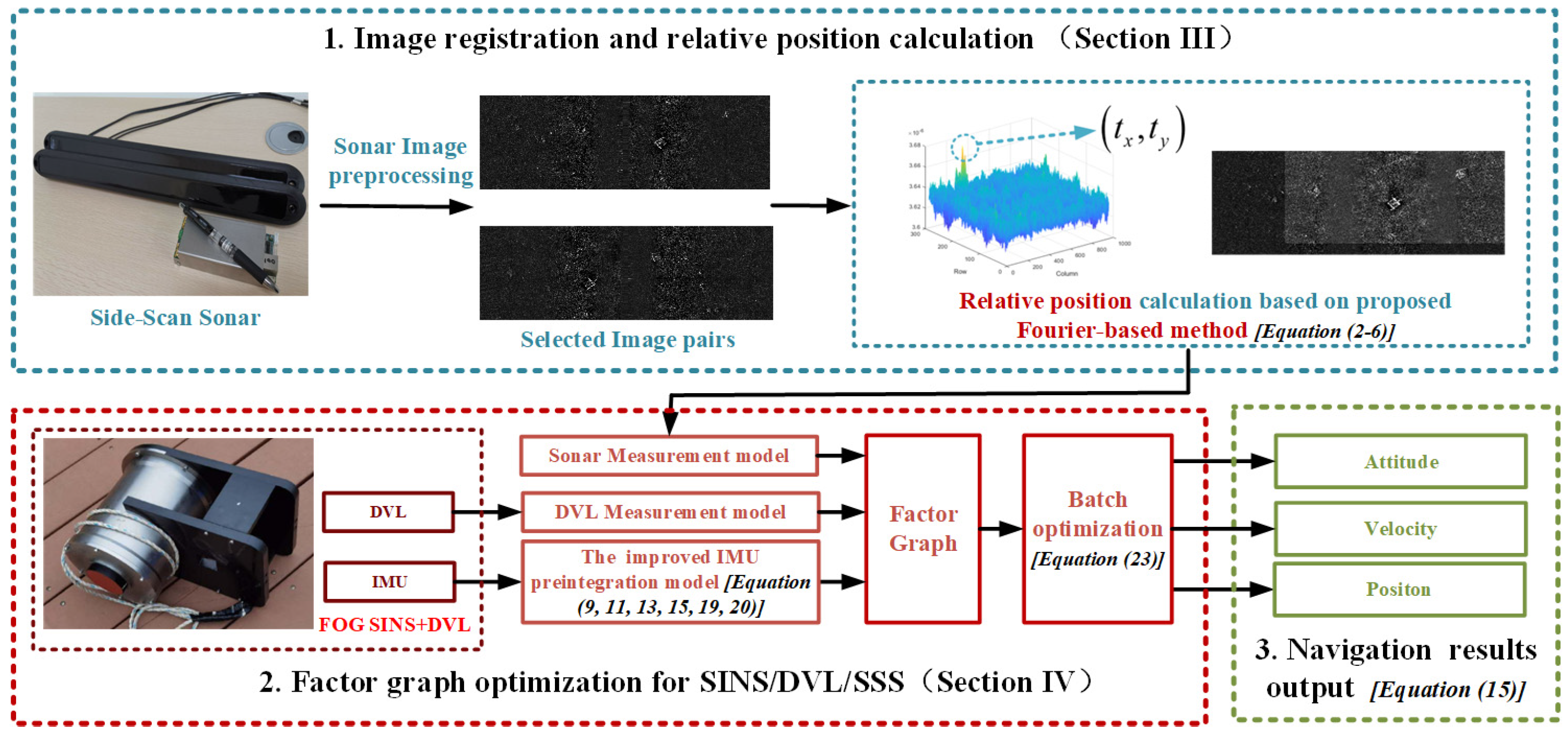
2. Overview

The proposed approach is outlined in Figure 1 and comprises three primary components.
(1)
Registration of side-scan sonar images
Including SSS image pair selection, image pair preprocessing, and Fourier-based registration, aiming to establish the spatial relationship between the SSS images. This will be demonstrated with details in Section 3.
(2)
Factor graph optimization
Based on the improved high-accuracy pre-integration model and DVL/SSS measurement residuals, as shown in Section 4, the state of the entire trajectory will be batch-optimized through FGO. The specifics of the FGO formulation are provided in Section 4.1. The improved IMU pre-integration model will be presented in Section 4.2. The residuals and Jacobian matrix will be demonstrated in Section 4.3 and Section 4.4.
(3)
Information output
After the states are estimated using FGO, the navigational information for the trajectory can be generated.

3. Fourier-Based Image Registration of SSS

This section provides a detailed account of the preprocessing of SSS imagery, along with an illustration of the Fourier-based registration.

3.1. Processing SSS Imagery

SSS images with similar positions are selected as SSS image pairs. The preprocessing of the SSS image, including the integration of the proposed brightness equalization, is essential before the calculation of AUV’s relative position.

3.1.1. Distortion Correction

SSS outputs a grayscale image arranged based on sound signal intensity over time. Therefore, the original SSS image exhibits distortion: features near the stitching line are compressed, while those further away are stretched. Additionally, the images of the seabed measured on the left and right sides are separated by the water column. Removing image distortion is the premise of obtaining relative position by using images.
The seabed lacking features is typically flat, and this flatness is often a contributing factor to the lack of features on the seabed. Assuming the seabed is flat, then Equation (1) holds true for the horizontal separation L f e a t u r e between a point and the stitching line.
L f e a t u r e = L s l o p e 2 H 2
L f e a t u r e represents the actual distance from a specific point on the seabed to the stitching line. L s l o p e represents the slant distance from the point to the SSS transducer. H represents the AUV’s vertical distance from the seabed provided by DVL.
The AUV’s elevation from the seabed can be obtained from the DVL or the water column, and the L s l o p e can be extracted from the original SSS image. Consequently, an image proportional to the seabed can be generated by processing the original SSS image. Additionally, correcting the longitudinal error in the SSS image is crucial, and this can be achieved by utilizing the forward DVL velocity data.

3.1.2. Brightness Correction

Even after distortion correction, SSS images may still exhibit prominent bright areas parallel to the AUV’s course, which is caused by the characteristics of SSS. The brightness of pixels in the SSS image is positively correlated with the intensity of the echo, which means that the place closer to the center baseline produces stronger echo and brighter pixels because of the smaller incident angle of the sound waves.
The original pixels in SSS imagery can adversely affect image matching due to their brightness. Consequently, it is crucial to mitigate the uneven brightness in the images.
The average brightness of the entire image, as well as the average brightness of individual columns, can be calculated. By doing so, we can ascertain the variance between them. Adjusting the pixel values of each column based on these deviations will ensure consistent brightness across the image.

3.2. Fourier-Based SSS Image Registration

When the AUV sailed to a similar position in zigzag for the second time, registration was employed to derive the positional relationship from SSS image pairs.
A Fourier-based method instead of traditional image registration algorithms is utilized, as it provides enhanced robustness against underwater noise disturbances. For two images from SSS, denoted as g x , y and f x , y , assuming a 2-dimension translation t x ,   t y between them, as shown in Equation (2).
f x , y = g x t x , y t y
Fourier transform to the both sides of the Equation (2), the result F u , v   G u , v is shown as (3)
F u , v = G u , v e i u t x + v t y
The normalized cross-power spectrum is illustrated in Equation (4). The robustness of Fourier-based registration to noise is attributed to the process normalized process in Equation (4), which can be viewed as a pre-whitening step.
C u , v = F u , v G * u , v F u , v G * u , v = e i u t x + v t y
Subsequently, through the inverse Fourier transform, the phase correlation matrix (PCM) can be obtained as shown in (5):
P u , v = F 1 C u , v
Finally, the position relationship is determined in Equation (6), which is the relative position measurement correct by sonar image pairs.
t x , t y = argmax u , v P u , v

4. SSS-Added Integrated Navigation System Based on FGO

An analysis of the error model and measurement model of the SSS-added integrated navigation system is presented. The frame nomenclature is in Table 1.

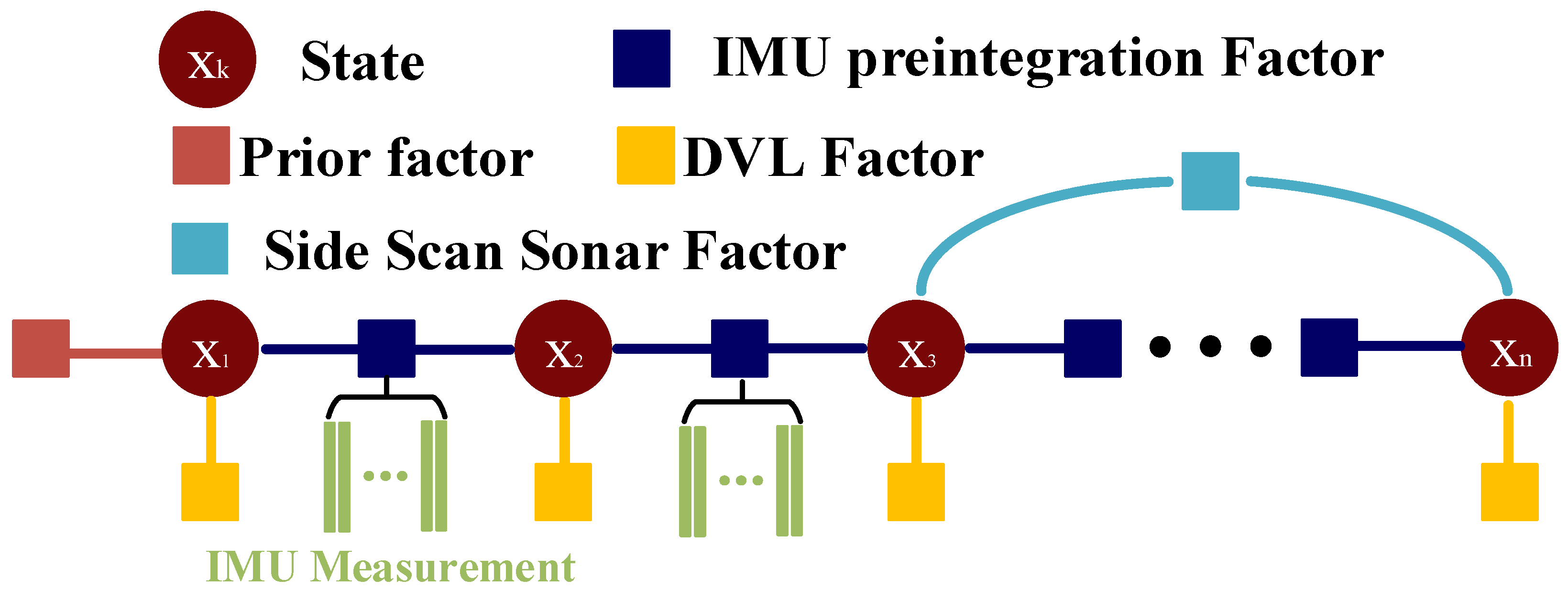
4.1. Formulation of FGO

In Figure 2, the structure of the proposed factor graph is depicted, using circles to represent the states x k , and squares to represent the factors or the residuals. The corresponding factor is explicitly defined in the subsequent sections.
At time step k, the state x k is defined as Equation (7),
x k = C b n k v k p k ε k k
where C b n k represent the attitude Direction Cosine Matrix (DCM), δ v k is velocity error, δ p k is the position error, and ε k , k are the bias of gyros and accelerators, respectively.
The state encompassing each time step in the factor graph can be expressed as (8).
X = x 1 x 2 x 3 x n 1 x n

4.2. The Improved IMU Pre-Integration Model

The existing pre-integration methods are generally applied to low-precision IMUs and usually do not take into account the Earth’s rotation, which decreases the performance of high-precision IMUs. In this section, an improved pre-integration model that takes into account the Earth’s rotation is proposed. The IMU pre-integration in this research includes attitude pre-integration, velocity pre-integration, and position pre-integration, which are illustrated as follows.

4.2.1. Attitude Updating and Attitude Pre-Integration

In the improved pre-integration model that considers the Earth’s rotation, the form of attitude pre-integration is consistent with that of conventional attitude pre-integration. The attitude pre-integration from time instant i to time instant j is defined as (9), where the Exp . transforms the rotation vector to DCM.
Δ R ˜ i j = ˙ k = i j 1 Exp ( ( ω ˜ k b g , k η g d , k ) Δ t )
The existing attitude updating method for FGO neglected the rotation of the n frame, which is expressed as (10).
C b j n j = C b i n i Δ R ˜ i j
However, taking into account the variation of the n frame over time, the attitude updating with the pre-integration is
C b j n j = C n i n j C b i n i Δ R ˜ i j
where the C n i n j is the DCM of the n frame from time i to time j.

4.2.2. Velocity Updating and Velocity Pre-Integration

The existing velocity pre-integration for FGO is expressed as (12), Δ v k which is the integral of the relative force in the b frame.
Δ v ˜ i j = k = i j 1 C b ( i ) n ( i ) C b ( k ) b ( i ) Δ v k
The improved method, defined as (13), differs significantly from conventional velocity pre-integration. Both the contribution of Earth’s rotation C n ( i ) n ( k ) and the compensation for paddle errors Δ v scul ( k ) b ( k 1 ) are considered to enhance performance. The consideration of the Earth’s rotation contributes to the heading convergence through the Earth’s rotation, which is not achievable with the traditional method (12).
Δ v ˜ i j = k = i j 1 C n ( i ) n ( k ) C b ( i ) n ( i ) C b ( k ) b ( i ) Δ v k + Δ v rot ( k ) b ( k 1 ) + Δ v scul ( k ) b ( k 1 )
Δ v rot ( k ) b ( k 1 ) is the compensation value for rotational velocity error, which is caused by the rotation of the specific force during the time interval. It is defined as Δ v rot ( k ) b ( k 1 ) = 1 2 Δ θ k ^ Δ v k , where Δ θ k is the integration of gyroscope sampling, ^ is the skew operator. Δ t is the time gap between time i and time j. Δ v scul ( k ) b ( k 1 ) will be given in the formula below, we used a 2-subsample paddle error compensation in the proposed method, which is
Δ v scul ( m ) b ( m 1 ) = 2 3 ( Δ θ m 1 ^ Δ v m 2 + Δ v m 1 ^ Δ θ m 2 )
where Δ θ m i represents the i-th subsample from the gyroscope; Δ v m i represents the sampling velocity increment of the i-th accelerometer subsample. The velocity update formula using pre-integration is as follows:
v e n j n j = Δ v ˜ i j + k = i j 1 g n Δ t + v e n i n i

4.2.3. Position Updating and Position Pre-Integration

The general position updating equation is as follows:
p ( m ) = p ( m 1 ) + M p v v e n ( m 1 ) n ( m 1 ) Δ t
where p = L λ h T represents the position of the vehicle, including Longitude, Latitude, and Depth; v e n ( m 1 ) n ( m 1 ) is the projection of the velocity of the vehicle to the Earth’s surface in the n frame at the time ( m 1 ) . And M p v is a matrix consisting of parameters related to the vehicular position on the Earth, and it is defined as (17):
M p v = 0 1 / R M + h 0 sec L / R N + h 0 0 0 0 1
where, R M = R N 1 e 2 1 e 2 sin 2 L , R N = R e 1 e 2 sin 2 L , e = R e 2 R p 2 R e . R e and R p are the short and long axis radius of the Earth, respectively. e represents the eccentricity of the Earth. Assuming that the motion area of the AUV remains relatively constant, it can be considered that M p v remains constant during each pre-integration. Therefore,
p j = p i + M p v k = i j 1 v e n ( k ) n ( k ) Δ t
So, the improved position pre-integration is defined as
Δ p ˜ i j = ˙ 1 M p v p j p i v e n ( i ) n ( i ) Δ T = k = i j 1 Δ v i k Δ t
And the position update formula using pre-integration is as follows:
p j = p i + M p v Δ p ˜ i j + v e n ( i ) n ( i ) Δ T + 1 2 g n Δ T 2
So far, the definition of the improved IMU pre-integration has been listed in Formulas (9), (13) and (19), respectively. The navigation information update equation using improved pre-integration can be found in Equations (11), (15) and (20).

4.3. Residuals and Jacobian Matrix of SINS/DVL/SSS Integration

The INS residuals r Δ I N S = r Δ R i j r Δ v i j r Δ p i j r b g r b a T can be expressed as (21), the r Δ R i j   r Δ v i j   r Δ p i j   r b g   r b a represent the attitude, velocity, position, accelerometers, and gyroscopes residuals, respectively.
r Δ R i j = L o g Δ R ˜ i j T C n i n j C b i n i 1 C b j n j r Δ v i j = v e n j n j v e n i n i g n Δ T Δ v ˜ i j r Δ p i j = 1 M p v p j p i v e n ( i ) n ( i ) Δ T 1 2 g n Δ T 2 Δ p ˜ i j r b g = b g , j b g , i r b a = b a , j b a , i
The DVL measurement residuals r v D V L and the SSS measurement residuals can be expressed as (22), the Δ p ˜ S S S a b indicates the relative position error calculated by (6)
r v D V L = v i C b ( i ) n ( i ) v D V L r Δ p S S S a b = 1 M p v p b p a Δ p ˜ S S S a b
Finally, the whole state can be optimally estimated by the following expression,
X * = arg min k r Δ I N S k I N S 2 + r v D V L k D V L 2 + r Δ p S S S i j k S S S 2 + r P R I O R k P R I O R 2
where k I N S   k D V L   k S S S   k P R I O R are all convince matrixes. k I N S is the weight of the INS residuals, determined by the accuracy of the IMU, while k D V L and k S S S are the weight of the DVL measurement residuals and SSS measurement residuals, determined by the measurement noise of the DVL and the matching noise of the SSS, separately. And P R I O R can be obtained through marginalization or set directly.

4.4. Jacobian Matrix

The Jacobian matrix of the pre-integration factor for each state is as follows:
J I M U _ P R E = J r 1 r Δ R ˜ i j C b j n j 1 I T ( ω i n n ^ ) C b ( i ) n ( i ) 0 3 × 3 0 3 × 3 J r 1 r Δ R ˜ i j Δ R ˜ i j T I T ( ω i n n ^ ) C b i n i 1 J r Δ R ˜ i j b g , i 0 3 × 3 J r 1 r Δ R ˜ i j 0 3 × 3 0 3 × 3 0 3 × 3 0 3 × 3 Δ v ˜ i j C b i n i I 3 × 3 0 3 × 3 Δ v ˜ i j b g , i Δ v ˜ i j b a , i 0 3 × 3 I 3 × 3 0 3 × 3 0 3 × 3 0 3 × 3 Δ p ˜ i j C b i n i Δ T I 3 × 3 Δ p ˜ i j b g , i Δ p ˜ i j b a , i 0 3 × 3 0 3 × 3 I 3 × 3 0 3 × 3 0 3 × 3 0 3 × 3 0 3 × 3 0 3 × 3 I 3 × 3 0 3 × 3 0 3 × 3 0 3 × 3 0 3 × 3 I 3 × 3 0 3 × 3 0 3 × 3 0 3 × 3 0 3 × 3 0 3 × 3 I 3 × 3 0 3 × 3 0 3 × 3 0 3 × 3 0 3 × 3 I 3 × 3
where the   Δ v ˜ i j C b i n i   , Δ p ˜ i j C b i n i   , Δ R ˜ i j b g , i , Δ v ˜ i j b g , i , Δ p ˜ i j b g , i , Δ v ˜ i j b a , i , Δ p ˜ i j b a , i need to be obtained from recursion, as follows:
Δ v ˜ i j C b i n i = k = i j 1 C n ( i ) n ( k ) C b ( i ) n ( i ) C b ( k ) b ( i ) Δ v k + Δ v rot ( k ) b ( k 1 ) + Δ v scul ( k ) b ( k 1 ) ^ Δ p ˜ i j C b i n i = k = i j 1 Δ v ˜ i k C b i n i Δ t Δ R ˜ i j b g , i = k = i j 1 Δ R ˜ k + 1 , j J r , k Δ t Δ v ˜ i j b g , i = k = i j 1 C n ( i ) n ( k ) C b ( i ) n ( i ) Δ R ˜ i k Δ v k ^ Δ R ˜ i k b g , i Δ t Δ p ˜ i j b g , i = k = i j 1 Δ v ˜ i k b g , i Δ t Δ v ˜ i j b a , i = k = i j 1 C n ( i ) n ( k ) C b ( i ) n ( i ) Δ R ˜ i k Δ t Δ p ˜ i j b a , i = k = i j 1 Δ v ˜ i k b a , i Δ t

5. AUV Marine Experiment

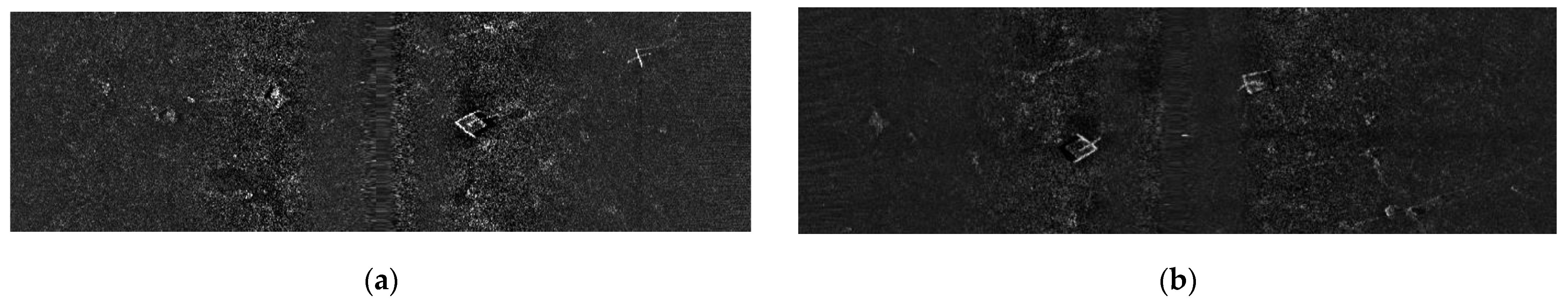
5.1. Experimental Outcomes of Image Registration

In this section, the performance of the feature-based method and the proposed method are contrasted by testing them on a simple pair of SSS images shown in Figure 3. Figure 4 shows the result of the feature-based method. It demonstrated that the extracted features only partially matched, and the matches were clearly incorrect, as the differing perspectives and the acoustic noise underwater altered the appearance of individual features. Therefore, the determination of the relative position failed. This result, which is common in most of the seabed, clearly demonstrates that the registration method based on features is not effective for underwater conditions.
The same pair of SSS images underwent Fourier-based registration, and Figure 5 displays the result after the inverse Fourier transform. The coordinates of the maximum value in Figure 5a represent the displacement pixel quantities of the two images, and the unique and clear peak indicates that the Fourier-based method is not prone to large displacement errors, even in this dull environment. After the displacement of the overlapping image, shown in Figure 5b, it is demonstrated that the stone pedestal features are well aligned. Therefore, the accuracy of the Fourier-based registration method is affirmed.
Altogether, two conclusions are drawn from the experimental results on the marine AUV’s side-scan sonar images:
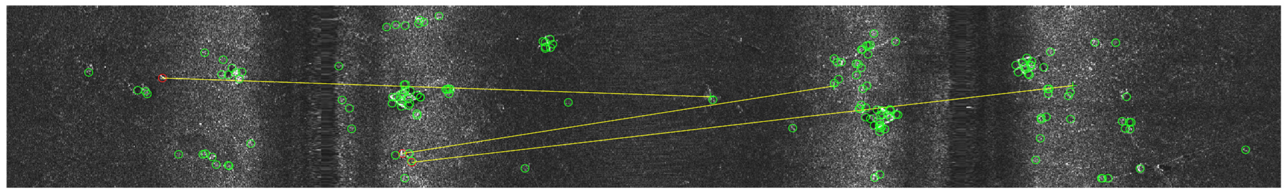
  • Due to the underwater acoustic noise, the conventional registration method based on features is unable to accomplish the task.
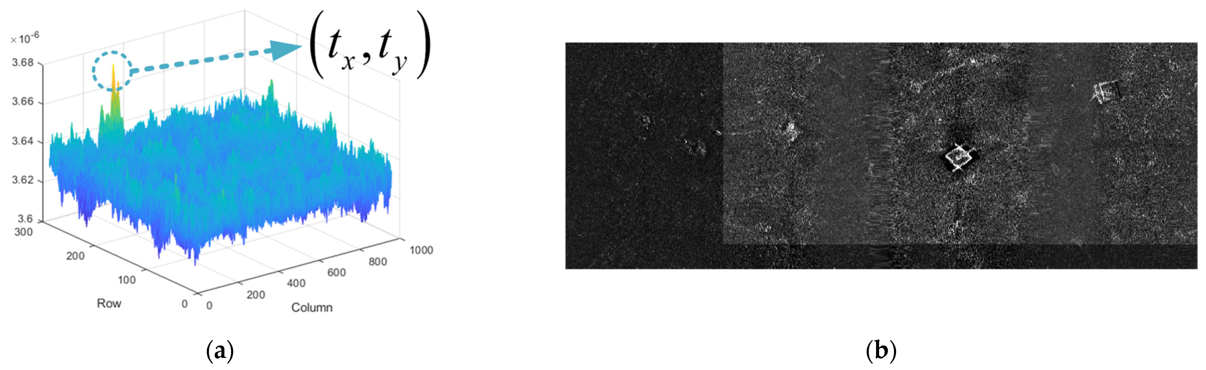
  • At the same time, by employing a Fourier-based registration method, the AUV’s relative position measurement at two passes through the same location can be obtained from paired SSS images.

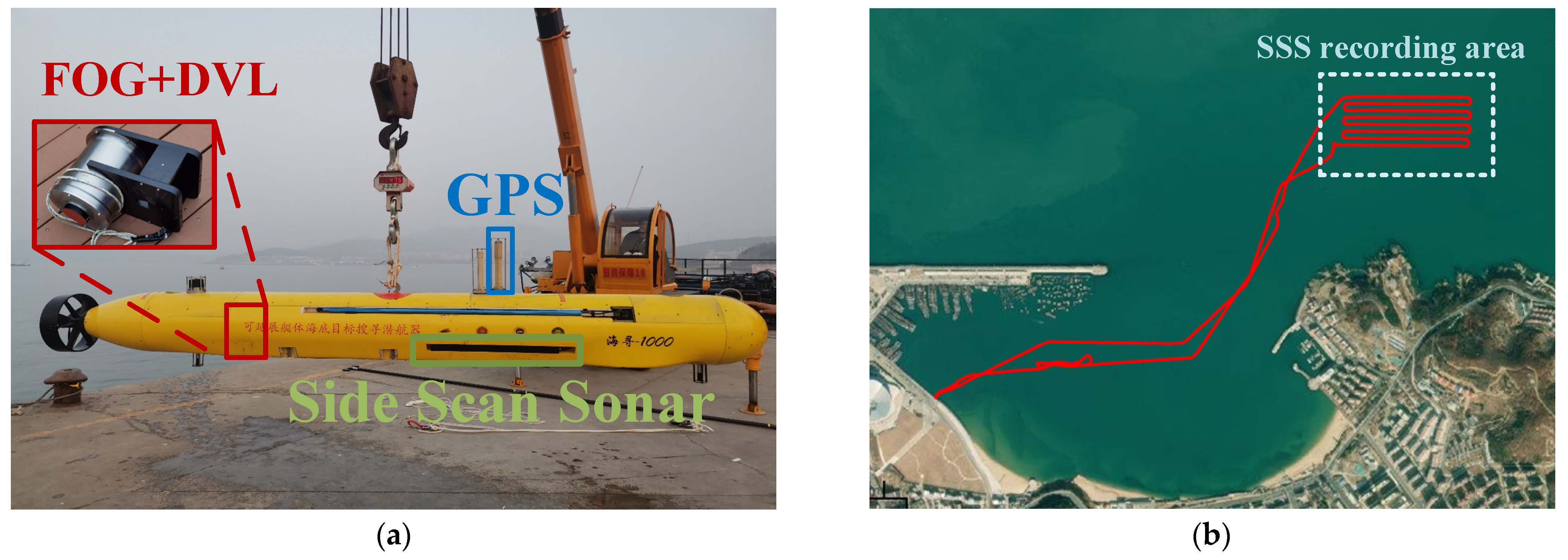
5.2. Setup for AUV’s Marine Experiments

The physical experiment takes place in Weihai, Shandong, and is set up on an AUV, where compensation has been made for the misalignment angle between the FOG SINS and DVL, as well as the lever-arm between the FOG SINS and SSS.
Table 2 displays the parameters of the sensors. Figure 6 illustrates the AUV setup and its trajectory during the experiment.
When the AUV is on the water surface, GPS measurements are considered as the true position. The FOG SINS provides the starting attitude, and the reference for the underwater trajectory is the smoothing result of the FOG-SINS/DVL/GPS measurements, which includes the entire voyage from submersion to resurfacing. Given that GPS provides position information at the beginning and end of the voyage, the underwater trajectory derived from this smoothing process can be considered reliable.
The algorithm verification data used for subsequent validation only encompasses the AUV’s activities on the water surface, diving, and zigzag maneuvers, deliberately excluding the surfaced portion of the AUV, thus simulating the absence of underwater position measurement.

5.3. Experimental Results of FGO-Based Navigation

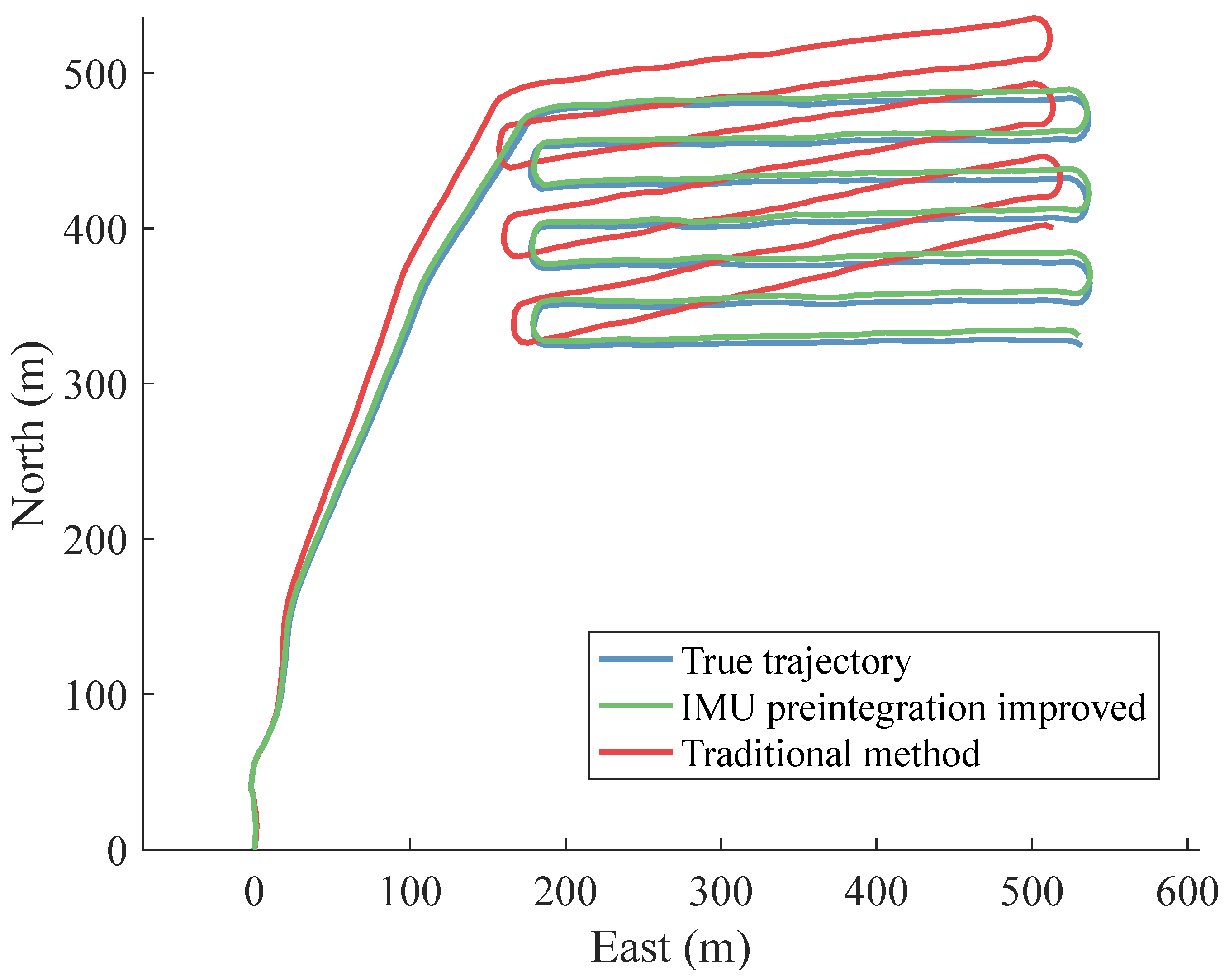
5.3.1. The Verification of the Improved Pre-Integration Method

In SINS/DVL integrated navigation, the lack of position measurement can lead to the accumulation of heading errors in AUVs, which is a primary source of positioning inaccuracies. To verify the error correction capability of the proposed pre-integration method on the AUV’s attitude, we introduced an additional 3 degrees of initial heading error to the initial attitude. There are two methods tested in the two situations, respectively:
  • The traditional FGO-based SINS/DVL integration navigation method, with an additional 3 degrees of initial heading error;
  • The proposed IMU pre-integration improved the FGO-based SINS/DVL method, also with an additional 3 degrees of initial heading error.
The trajectory comparison is in Figure 7. The blue line represents the actual trajectory, while the green line depicts the trajectory obtained through FGO-based SINS/DVL integrated navigation using the improved IMU pre-integration method. It is noteworthy that this trajectory closely aligns with the actual trajectory and remains unaffected by the extra initial heading error. In contrast, the red line demonstrates the outcome of traditional FGO-based SINS/DVL integrated navigation, which is significantly disrupted by the initial heading error. Notably, the improved IMU pre-integration method effectively rectifies the initial heading error, resulting in more precise position outcomes. Thus, it is more stable and requires less initial attitude accuracy.
Figure 7 illustrates that the traditional pre-integration method fails to account for the Earth’s rotational angular rate, resulting in an inability to compensate for attitude errors during SINS/DVL integration. Consequently, this leads to a progressive increase in position error over time. On the other hand, the proposed improved IMU pre-integration method effectively addresses the attitude error and demonstrates greater robustness.

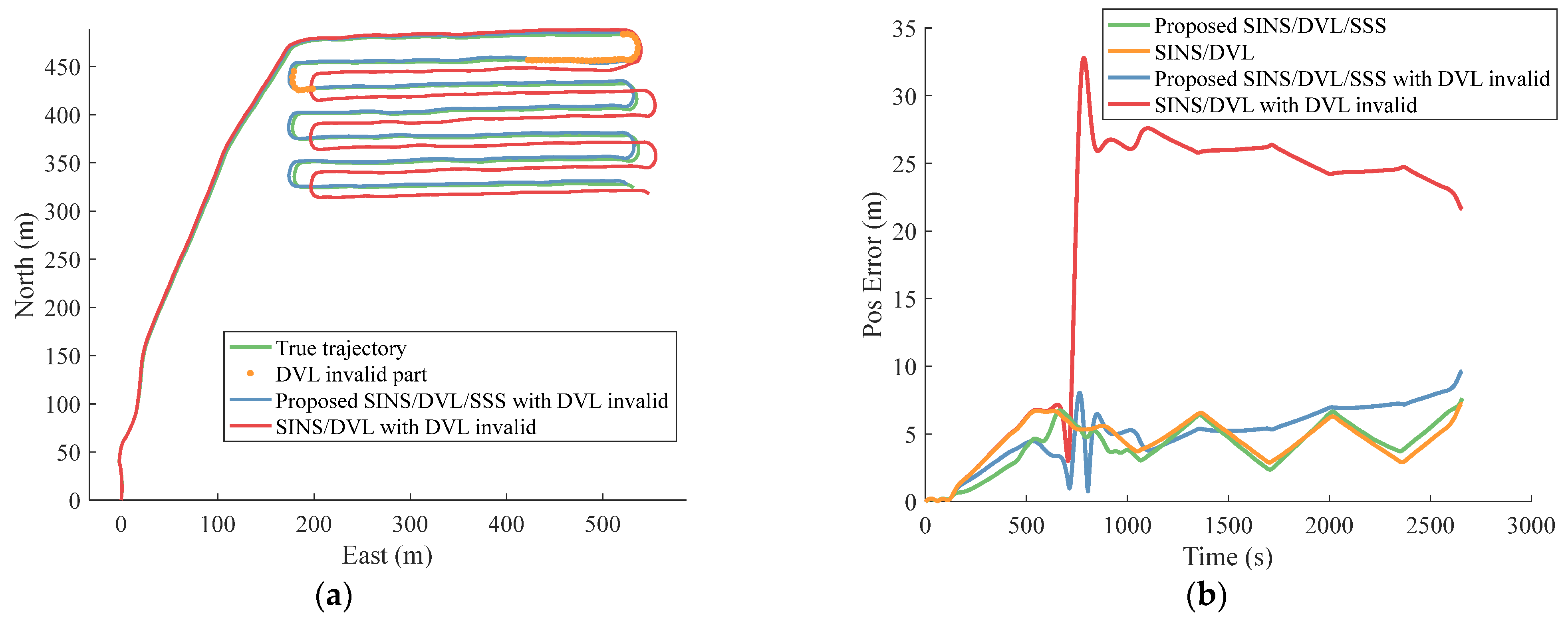
5.3.2. The Verification of the SSS Integrated Navigation Method

The significant errors in SINS/DVL integrated navigation primarily stem from DVL noise or failure. During the AUV seabed scans, the complex underwater environment can result in DVL measurements with substantial noise or even failure due to exceeding the DVL’s operational range or encountering diverse substrates.
Therefore, to verify the enhanced stability of the SINS/DVL system with the addition of integrated SSS, simulations were conducted using both the original data and simulated SINS/DVL data with partial DVL failure.
The method with SSS relative position compensation was implemented. After every 50 m of straight-line movement, the system will match the sonar image captured during this 50 m voyage with the image captured during the voyage before. This process provides relative position measurements. At the same time, a comparison was made using FGO-based SINS/DVL integrated navigation without added SSS measurements.
In all, there are two methods tested in the two situations, respectively.
  • Proposed SINS/DVL/SSS FGO-based method tested on original data.
  • SINS/DVL FGO based method tested on original data.
  • Proposed SINS/DVL/SSS FGO-based method tested with partial DVL failure.
  • SINS/DVL FGO based method tested with partial DVL failure.
The comparison trajectory with DVL partially invalidated is shown in Figure 8a, and the positioning error comparison is shown in Figure 8b. The average position error of the method is shown in Table 3.
Figure 8a shows the comparison of trajectory estimation under partial DVL failure. The green line is the true value of trajectory, and the orange dot above represents that the DVL here has lost its effective output. The trajectory output by the FGO-based SINS/DVL integrated navigation system is represented by the red line, while the proposed output trajectory incorporates relative position information from the SSS images, denoted by the blue line.
It is evident from Figure 8a that the normal integrated navigation method, without an SSS image, experiences position errors in the event of DVL failure. The accumulated error persists due to the absence of position measurements. In contrast, the proposed SINS/DVL/SSS integrated navigation is capable of maintaining a stable and complete trajectory. This is attributed to the relative position measurements provided by SSS and the utilization of batch processing characteristics of FGO.
Figure 8b shows the comparison of positioning errors of all four methods. In Figure 8b, the green and yellow lines depict the time-varying position errors of the navigation information output by the proposed SINS/DVL/SSS integrated navigation method and the SINS/DVL integrated navigation method, respectively. Meanwhile, the blue and red lines, respectively illustrate the position error of navigation information output by the proposed SINS/DVL/SSS method and the error output by the ordinary SINS/DVL method in the event of partial DVL failure.
Analysis of Figure 8b reveals that both the SINS/DVL method and the SINS/DVL/SSS method demonstrate accurate AUV trajectory calculations under normal DVL operation conditions. However, when faced with partial DVL failure, significant positioning errors were observed with the SINS/DVL method. In contrast, our proposed method, although initially affected by DVL failure, effectively mitigates position error divergence with the aid of the SSS’s relative position measurements. As a result, it yields only a slightly worse position error than that observed under fully effective DVL conditions.
Table 3 presents the average positioning errors of the two methods in two environments. The findings indicate that the proposed SINS/DVL/SSS integrated navigation method closely aligns with the traditional SINS/DVL method when the DVL is fully functional. However, in instances of partial DVL invalidity, the proposed method significantly mitigates the adverse effects stemming from DVL failure. Though the proposed method cannot completely eliminate the effects of DVL failure, which is because the position measurements provided by the SSS are not absolute but relative to the previous trajectory, it is clear that the integration of SSS can make navigation more robust against DVL failure.
In all, two conclusions can be drawn from the experimental results of the FGO-based navigation.
  • Unlike the traditional pre-integration methods, the improved IMU pre-integration method considered the Earth’s rotation and thus can utilize the Coriolis effect to correct heading errors, making the system more stable against initial heading errors.
  • Compared to traditional FGO-based SINS/DVL integrated navigation, the proposed integrated navigation with the addition of SSS position measurements could reduce the system’s divergence rate, particularly when the DVL data is partially unavailable, thereby enhancing the system’s robustness.

6. Conclusions

In this research, an FGO-based SINS/DVL/SSS integration algorithm is proposed, including a Fourier-based SSS image matching method and a high-precision inertial navigation pre-integration method. The Fourier-based SSS image-matching method could provide position measurements in a rigid underwater environment, ensuring long-term stability for AUVs. Meanwhile, the high-precision inertial navigation pre-integration method, considering the influence of the Earth’s rotation, allows a high-precision IMU to correct the attitude errors of the vehicle continuously by using the Earth’s rotation.
First, a Fourier-based method is proposed for obtaining relative positions from the SSS images, followed by the illustration of the integrated navigation method of SINS/DVL/SSS. A high-precision IMU pre-integration method considering the Earth’s rotation is proposed, and the corresponding FGO residual and Jacobian matrix forms are given. After that, the experiment of SSS image registration is carried out, and the experiment of the improved FGO-based integrated navigation method is also conducted under both normal and invalid DVL conditions.
Here are three principal conclusions:
  • Due to the dullness of underwater acoustic images and the influence of observation angles, traditional feature-based image registration methods cannot obtain relative positions. The Fourier-based registration method is not limited to isolated features but uses information from the entire image for registration, achieving better results and successfully extracting relative positional information in most cases.
  • Compared to the commonly used IMU pre-integration method, the high-accuracy IMU pre-integration proposed in the paper can better utilize the IMU with low bias instability to correct the attitude errors with the Earth’s rotation.
  • The method proposed to incorporate SSS as a position reference into the SINS/DVL navigation system not only supplements the position measurements for long-term underwater navigation of AUVs but also maintains the stability of the system’s position estimation in the event of DVL failure, thus improving the stability of the navigation system.

Author Contributions

Conceptualization, L.Z. and L.G.; Data curation, L.Z.; Formal analysis, L.Z.; Funding acquisition, Y.G.; Investigation, L.Z.; Methodology, L.Z.; Project administration, L.G.; Resources, L.Z.; Supervision, Y.G.; Visualization, L.G.; Writing—original draft, L.Z.; Writing—review & editing, L.G. All authors have read and agreed to the published version of the manuscript.

Funding

This research was funded by the Natural Science Foundation of China, grant number 61803118, and the Department of Science and Technology of Heilongjiang Province, grant number 2023ZX01A21.

Institutional Review Board Statement

Not applicable.

Informed Consent Statement

Not applicable.

Data Availability Statement

The data that support the findings of this study are available from the corresponding author upon reasonable request.

Conflicts of Interest

The funders had no role in the design of the study, in the collection, analyses, or interpretation of data, in the writing of the manuscript, or in the decision to publish the results.

References

  1. Ånonsen, K.B.; Mandt, M. Water Referenced Doppler Velocity Aiding for AUV Navigation. In Proceedings of the OCEANS 2022, Hampton Roads, VA, USA, 17–20 October 2022; pp. 1–8. [Google Scholar]
  2. Snyder, J. Doppler Velocity Log (DVL) Navigation for Observation-Class ROVs. In Proceedings of the OCEANS 2010 MTS/IEEE SEATTLE, Seattle, VA, USA, 20–23 September 2010; pp. 1–9. [Google Scholar]
  3. Zhang, B.; Ji, D.; Liu, S.; Zhu, X.; Xu, W. Autonomous Underwater Vehicle Navigation: A Review. Ocean Eng. 2023, 273, 113861. [Google Scholar] [CrossRef]
  4. Xu, X.; Gui, J.; Sun, Y.; Yao, Y.; Zhang, T. A Robust In-Motion Alignment Method With Inertial Sensors and Doppler Velocity Log. IEEE Trans. Instrum. Meas. 2021, 70, 1–13. [Google Scholar] [CrossRef]
  5. Huang, Y.; Zhang, Y.; Li, N.; Wu, Z.; Chambers, J.A. A Novel Robust Student’s t-Based Kalman Filter. IEEE Trans. Aerosp. Electron. Syst. 2017, 53, 1545–1554. [Google Scholar] [CrossRef]
  6. Yao, Y.; Xu, X.; Xu, X.; Klein, I. Virtual Beam Aided SINS/DVL Tightly Coupled Integration Method With Partial DVL Measurements. IEEE Trans. Veh. Technol. 2023, 72, 418–427. [Google Scholar] [CrossRef]
  7. Wang, D.; Xu, X.; Yao, Y.; Zhang, T.; Zhu, Y. A Novel SINS/DVL Tightly Integrated Navigation Method for Complex Environment. IEEE Trans. Instrum. Meas. 2020, 69, 5183–5196. [Google Scholar] [CrossRef]
  8. Rypkema, N.R.; Fischel, E.M.; Schmidt, H. Closed-Loop Single-Beacon Passive Acoustic Navigation for Low-Cost Autonomous Underwater Vehicles. In Proceedings of the 2018 IEEE/RSJ International Conference on Intelligent Robots and Systems (IROS), Madrid, Spain, 1–5 October 2018; pp. 641–648. [Google Scholar]
  9. Melo, J.; Matos, A. Survey on Advances on Terrain Based Navigation for Autonomous Underwater Vehicles. Ocean. Eng. 2017, 139, 250–264. [Google Scholar] [CrossRef]
  10. Rajani, H.; Gracias, N.; Garcia, R. A Convolutional Vision Transformer for Semantic Segmentation of Side-Scan Sonar Data. Ocean Eng. 2023, 286, 115647. [Google Scholar] [CrossRef]
  11. Tang, Z.; Luo, Z.; Jiang, L.; Ma, G. A Novel High Precision Mosaic Method for Sonar Video Sequence. Multimed. Tools Appl. 2021, 80, 14429–14458. [Google Scholar] [CrossRef]
  12. Zhang, W.; Zhou, T.; Xu, C.; Liu, M. A SIFT-Like Feature Detector and Descriptor for Multibeam Sonar Imaging. J. Sens. 2021, 2021, 8845814. [Google Scholar] [CrossRef]
  13. Barfoot, T.D. State Estimation for Robotics, 1st ed.; Cambridge University Press: Cambridge, UK, 2017; ISBN 978-1-107-15939-6. [Google Scholar]
  14. Xu, Y.; Zheng, R.; Zhang, S.; Liu, M. Robust Inertial-Aided Underwater Localization Based on Imaging Sonar Keyframes. IEEE Trans. Instrum. Meas. 2022, 71, 1–12. [Google Scholar] [CrossRef]
  15. Franchi, M.; Ridolfi, A.; Pagliai, M. A Forward-Looking SONAR and Dynamic Model-Based AUV Navigation Strategy: Preliminary Validation with FeelHippo AUV. Ocean Eng. 2020, 196, 106770. [Google Scholar] [CrossRef]
  16. Qin, T.; Li, P.; Shen, S. VINS-Mono: A Robust and Versatile Monocular Visual-Inertial State Estimator. IEEE Trans. Robot. 2018, 34, 1004–1020. [Google Scholar] [CrossRef]
  17. Shan, T.; Englot, B.; Meyers, D.; Wang, W.; Ratti, C.; Rus, D. LIO-SAM: Tightly-Coupled Lidar Inertial Odometry via Smoothing and Mapping. In Proceedings of the 2020 IEEE/RSJ International Conference on Intelligent Robots and Systems (IROS), Las Vegas, NV, USA, 24 October 2020; pp. 5135–5142. [Google Scholar]
  18. Zhou, H.; Ye, X. A Unified Initial Alignment Method of SINS Based on FGO. IEEE Trans. Ind. Electron. 2023, 70, 11795–11803. [Google Scholar] [CrossRef]
  19. Forster, C.; Carlone, L.; Dellaert, F.; Scaramuzza, D. On-Manifold Preintegration for Real-Time Visual-Inertial Odometry. IEEE Trans. Robot. 2017, 33, 1–21. [Google Scholar] [CrossRef]
Figure 1. The framework of the proposed method.
Jmse 12 00313 g001
Figure 2. Factor graph structure of the proposed method.
Jmse 12 00313 g002
Figure 3. (a) Original SSS result 1; (b) Original SSS result 2.
Jmse 12 00313 g003
Figure 4. The feature-based method did not produce successful registration results.
Jmse 12 00313 g004
Figure 5. The result of the proposed Fourier-based registration method. (a) The phase collection results on SSS images; (b) Overlapping the original SSS image 1 and SSS image 2.
Jmse 12 00313 g005
Figure 6. Physical experiment setup. (a) The sensors equipped on the AUV; (b) The experiment trajectory (the red line) and the SSS recording area.
Jmse 12 00313 g006
Figure 7. Trajectory comparison.
Jmse 12 00313 g007
Figure 8. (a) The trajectory comparison with partial DVL failure; (b) The positioning error comparison.
Jmse 12 00313 g008
Table 1. Nomenclature.
Symbol Description
nIdeal local level navigation frame
bBody frame
eEarth frame
iNonrotating inertial frame
Table 2. Parameters of the initial sensors and DVL.
ParametersGyro Bias
Stability
Gyro Random WalkGyro Scale Factor AccuracyAccelerator Monthly Bias
Repeatability
DVL Long Term
Accuracy
Value<0.01°/h<0.001°/√h<10 ppm<20 μg0.5% ± 0.1 cm/s
Table 3. The comparison of average positioning error.
Condition\MethodAverage Positioning Error
of SINS/DVL (m)
Average Positioning Error
of SINS/DVL/SSS (m)
DVL all valid4.49384.1521
DVL partially invalid19.50695.0280
Disclaimer/Publisher’s Note: The statements, opinions and data contained in all publications are solely those of the individual author(s) and contributor(s) and not of MDPI and/or the editor(s). MDPI and/or the editor(s) disclaim responsibility for any injury to people or property resulting from any ideas, methods, instructions or products referred to in the content.

