1. Introduction
Due to the advantages of lower cost and better durability, the wide-shallow concrete bucket foundation has a great potential in coastal and ocean engineering, and it can be used as the foundation of an offshore deep-water wharf, breakwater, or offshore wind turbine. Normally, the rigidity of the wide-shallow concrete bucket foundation is relatively small due to its large diameter and shallow penetration depth. However, by adding the inner bucket and cruciform skirts, both the bearing capacity and rigidity of the bucket foundation will increase significantly [
1]. A typical application of such a configuration is a deep-water wharf, as shown in
Figure 1.
The inner bucket and cruciform skirt significantly increase the total area of the bottom and skirt; therefore, the foundation will be subjected to larger penetration resistance during its installation process. In addition, soil heaving will occur in each compartment separated by the inner bucket and cruciform skirt, which may prevent the foundation from reaching the designed installation depth and affect its post-installation bearing capacity. However, current research on the installation of bucket foundations mainly focuses on the ones with no compartment. The bucket foundation was first applied in an actual engineering project in 1994, and Tjelta [
2], through research on the measured data, found that installation methods, including self-weight penetration, pressing penetration, and suction-assisted penetration, have a significant impact on the soil flow mechanism. Iskander et al. [
3] conducted 1g indoor experiments on the penetration and extraction behavior of suction bucket foundations in clay and sand and explained the variation of penetration resistance and soil heaving. Chen et al. [
4] focused on the influence of different installation methods on the penetration process and installation effect of bucket foundations, studying the impact of different installation methods on the penetration process. Zhai et al. [
5] also analyzed how to reduce penetration resistance through indoor experiments. Wang et al. [
6] used the arbitrary Lagrangian–Eulerian (ALE) method to simulate the installation process of suction buckets and compared the difference in penetration resistance and soil heaving under different installation methods. Xiao et al. [
7] studied the changes in penetration resistance and soil flow mechanism during the penetration process of a single bucket foundation, considering the strain softening and rate effect of soil using the coupled Eulerian–Lagrangian (CEL) method. The adverse effects of bucket penetration-induced soil heaving and softening on the ultimate bearing capacity were also studied [
8]. Jin et al. [
9] used the smoothed particle hydrodynamics (SPH) method to simulate the penetration process of bucket foundations in sand.
There have been few studies on bucket foundations with multiple compartments, mostly focusing on on-site or indoor experiments. Liu et al. [
10] studied a new type of seven-compartment suction bucket shallow foundation (CBSF) used in a wind farm project in Jiangsu, China. Zhang et al. [
11] conducted a large-scale model study on the installation speed, penetration resistance, and levelness of the foundation in typical saturated silty clay for the seven-compartment suction bucket.
However, overall, there is still a lack of relevant research using three-dimensional large deformation numerical simulation methods to simulate the penetration process of bucket foundations with internal buckets and cruciform skirts in soil and analyze the penetration resistance and soil flow characteristics with consideration of soil softening properties.
When the ratio of the diameter of the inner bucket to that of the outer bucket changes, the height of soil heave inside each compartment during the installation process may vary accordingly. As the foundation cover contacts the heaved soil inside the compartment, sinking of the foundation will be halted. In such case, the soils within some compartments are still not in contact with the foundation cover after installation, which will obviously reduce the post-installation vertical bearing capacity of the foundation. Therefore, it is necessary to study soil heaving and penetration resistance during the installation of a bucket foundation with inner bucket and cruciform skirts in clay considering soil remolding under different ratios of the diameter of the inner bucket to that of the outer bucket. The bucket foundation with inner bucket and cruciform skirts has the optimal ratio of the diameter of the inner bucket to that of the outer bucket when the height of the soil heaving in the inner and outer compartments is almost equal after installation.
Large deformation numerical analysis is required to model the installation of the bucket foundation with inner bucket and cruciform skirts in clay. In the literature, there are three large deformation numerical methods by which to simulate the installation of the bucket foundation in clay; these include the ALE method [
7], the remeshing and interpolation technique by small strain (RITSS) [
8], and the CEL method [
7]. For the ALE method, a new mesh is created when the elements have obvious distortion. Then, the variables are mapped from the old mesh to the new mesh, which can accurately define material boundaries and complex contact interactions. However, it is mostly applied to solve plane strain or axisymmetric problems due to the limitation of computational efficiency. The RITSS method falls into the category of the ALE method in nature [
12], but the topological relationship between its old mesh and new mesh can be changed. Nevertheless, it requires the user to write a program to implement the entire calculation process, and the realization of the interpolation of the variables from the old mesh to the new mesh is challenging. The CEL method is a new finite element analysis method for large deformations, which combines the Eulerian analysis method and Lagrangian analysis method. As the CEL method can better simulate the deformation of the material in the Eulerian mesh, it can effectively solve the large deformation problems such as mesh and element distortions in the traditional Lagrangian domain [
13].
In this study, a three-dimensional large deformation finite element model incorporating the effect of soil remolding was established to model the installation of a bucket foundation with inner bucket and cruciform skirt in clay using the CEL method. The influences of the inner bucket and cruciform skirts on the soil heaving and penetration resistance during the installation of the bucket foundation in clay were analyzed and discussed. Meanwhile, the evolution of soil remolding at different penetration depths was demonstrated. The contribution of the resistance from each component of the foundation to the total penetration resistance was analyzed. The optimal ratio of the diameter of the inner bucket to that of the outer bucket was proposed based on theoretical analysis and validated by the numerical results. Key findings were obtained and discussed from the numerical results, and recommendations were made.
3. Numerical Results
3.1. Soil Flow and Heaving in Each Compartment
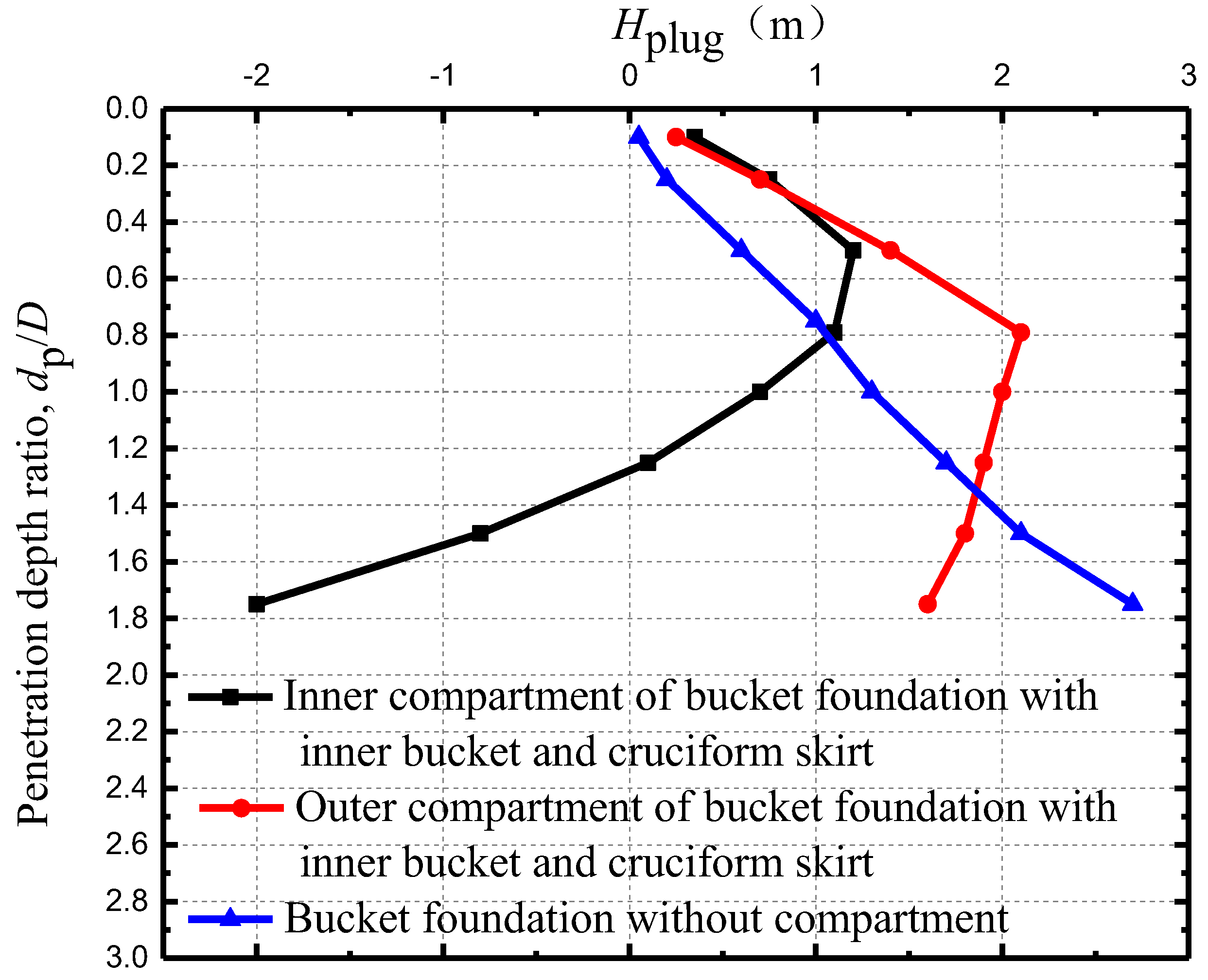
During the penetration of the bucket foundation, the soil will be squeezed by the skirts; therefore, the height of the soil surface inside the bucket will vary. If soil heaving happens inside the bucket, the foundation cannot be installed to the predetermined design depth. As a consequence, the actual bearing capacity will be less than the design bearing capacity.
The average height of the soil surface inside the bucket foundation relative to the original mud surface is defined as
Hplug. If it is positive, it indicates that the soil surface inside the bucket is higher than the original mud surface. Otherwise, the soil inside the bucket settles. Take the base case (
Din =
D/2) as an example; the comparison of
Hplug in the inner or outer compartment of the bucket foundation with and without inner bucket and cruciform skirts at different penetration depth ratio (
dp/
D) is shown in
Figure 4.
It can be seen from
Figure 4 that the height of the soil surface in the bucket foundation without compartment continuously increases with the penetration depth ratio. With the increase of the penetration depth ratio, the soils displaced by the skirt are inclined to flow into the bucket. This is because the earth pressure within the bucket decreases with the increase of the penetration depth ratio due to the increase of the soil strength with depth. For the foundation with inner bucket and cruciform skirts during the shallow penetration, the
Hplug is significantly higher than that of the bucket foundation without compartment. This is due to the added inner bucket and cruciform skirts squeezed more soil during the penetration, which gradually flowed into the inner or outer compartment. As the penetration depth ratio increases (i.e.,
dp/
D > 0.5 for the inner compartment and
dp/
D > 0.8 for the outer compartment), the
Hplug decreases with the increase of the penetration depth ratio. The main reason lies in the larger friction resistance caused by the inner bucket and cruciform skirt, which prevents the soil from flowing into the inner or outer compartment.
Meanwhile, it can be seen from
Figure 4 that with further penetration, the difference of the
Hplug between the inner and outer compartment becomes greater. Take
dp/
D = 1.5 as an example; the
Hplug in the outer compartment is about 1.7 m, which prevents the bucket foundation to penetrate into the predetermined depth and correspondingly its post-installation bearing capacity reduces. The
Hplug in the outer compartment is about 1.0 m lower than the original mud surface, which greatly decreases the vertical bearing capacity of the foundation due to non-contact between the lid of the bucket and the soil.
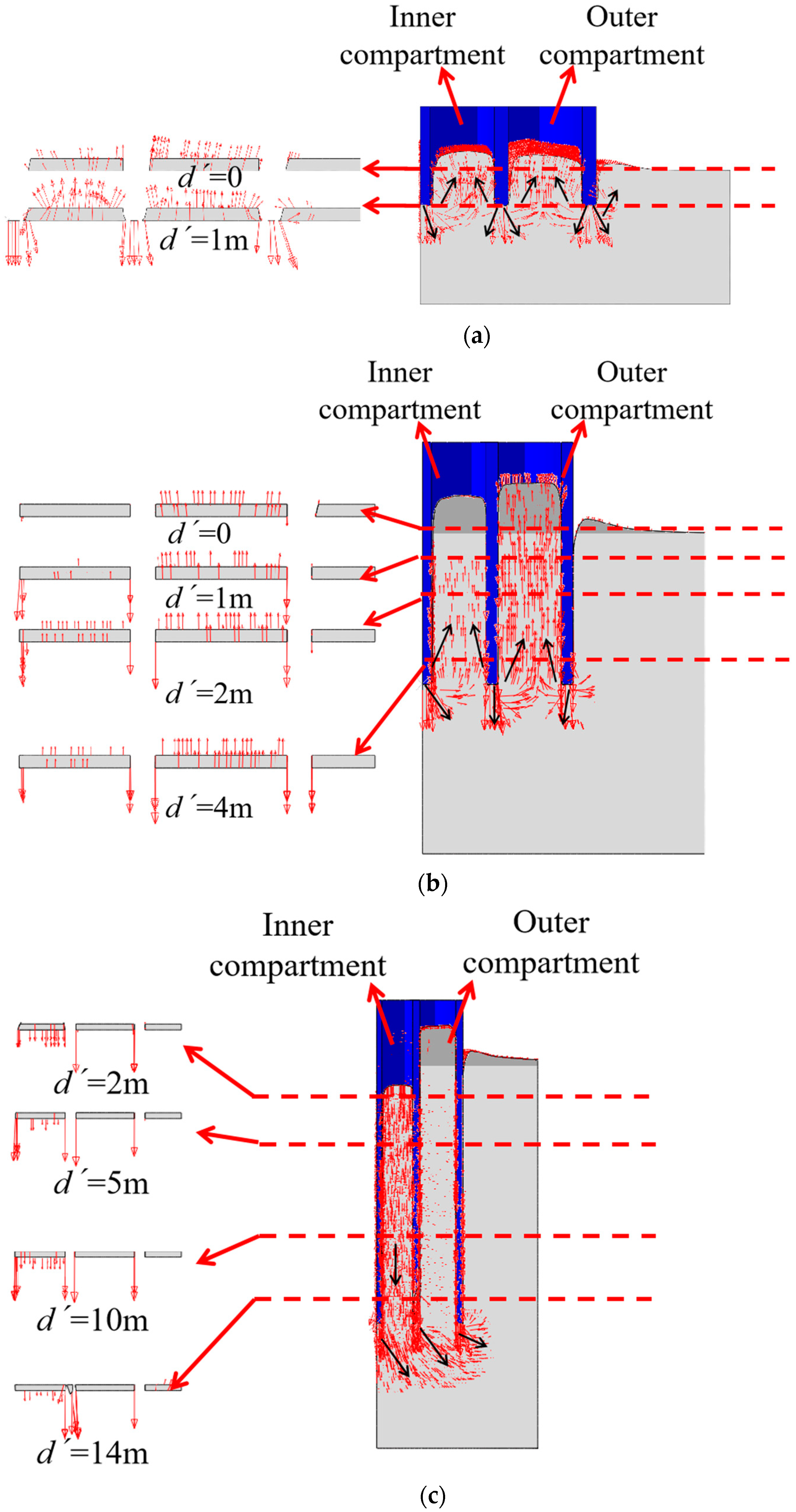
The evolution of the soil surface height in each compartment has correlation with the soil flow.
Figure 5 is the section view of the soil flow velocity vector at different positions and penetration depths (i.e., the section view is the soil flow along the section 1-1’ in
Figure 2b).
Figure 5a reflects the trend of soil flow during shallow penetration (
d/
D = 0.1). It can be seen that the soil around each skirt flows downwards and then evenly flows to both sides. As the penetration depth increases to
d/
D = 0.5 in
Figure 5b, and since the outer boundary of the bucket is closer to the semi-infinite space and the inner boundary of the bucket is limited, the passive earth pressure inside the bucket is lower than that of the outside. The soil is more inclined to flow in the compartment. When the penetration depth further increases to
d/
D = 1.5 in
Figure 5c, the contact area between the skirt and the soil also increases. The influence of side friction during the penetration of the foundation cannot be ignored. The larger frictional resistance in the inner and outer compartments not only hinders the upward flow of the soil (such as that in the outer compartment), but also pushes a large amount of soil to move downward together (such as that in the inner compartment).
3.2. Penetration Resistance
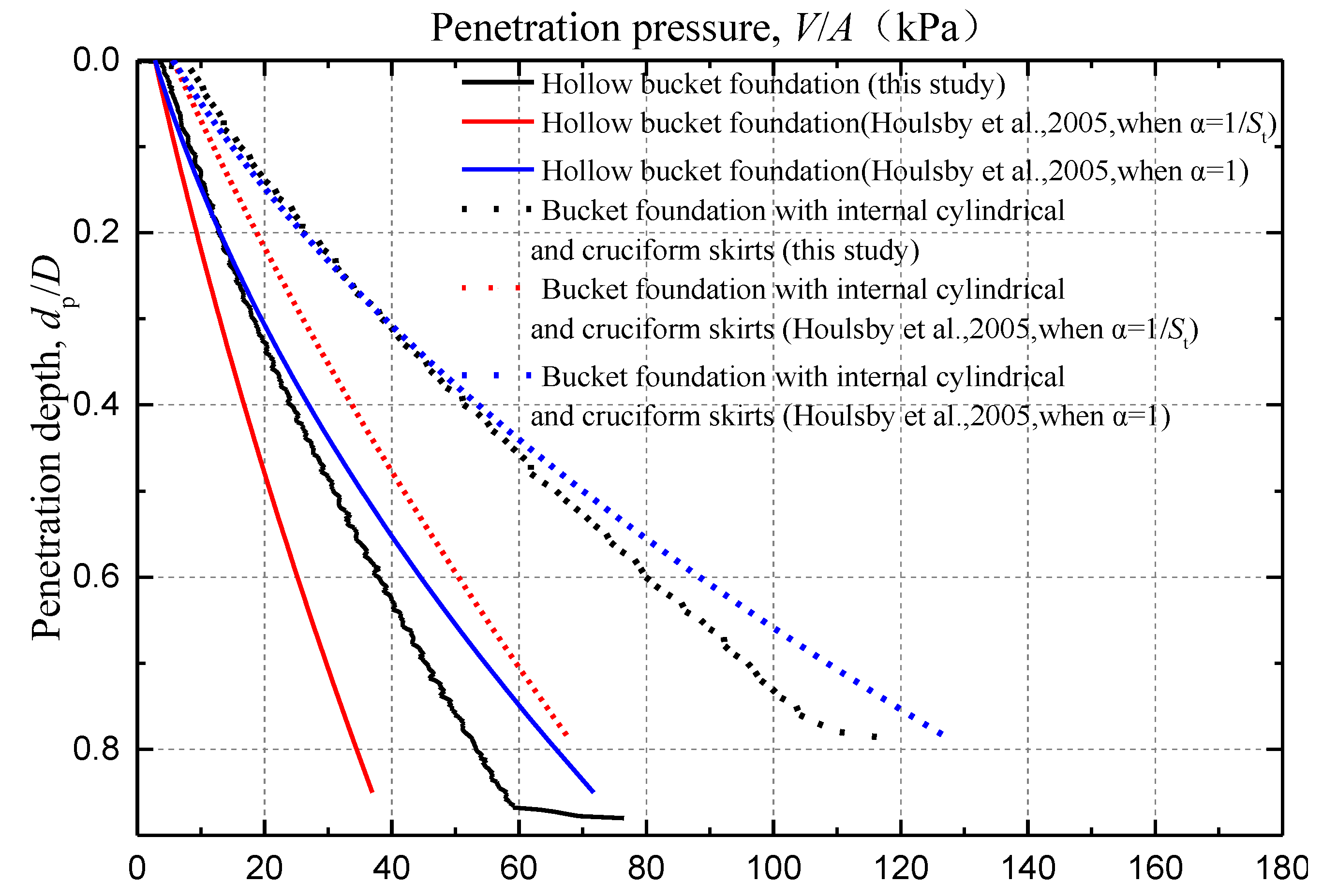
Take
d/
D = 1 as an example, the total penetration resistances of the bucket foundation with inner bucket and cruciform skirts and those of the hollow bucket foundation calculated by the CEL model in this study and the method in Houlsby and Byrne (2005) are shown in
Figure 6. Due to the inclusion of the internal cylindrical and the cruciform skirts, the bucket foundation has a significantly higher penetration resistance than the hollow bucket foundation.
When the foundation was installed to a certain depth, it can be seen from the CEL results in
Figure 6 that the penetration resistance suddenly changed, which is due to the soil heave inside the compartment. When the soils inside the bucket started to contact the bucket lid, the installation resistance suddenly increased, which affects the subsequent penetration of the bucket. As the bucket cannot be installed into the design depth, the in-place stability of the bucket foundation will be affected.
Houlsby and Byrne [
24] studied the penetration resistance of hollow bucket foundations based on the theory of limit equilibrium, for which the penetration resistance is equal to the sum of the side friction resistance and the end bearing capacity at the bottom of the skirts. The theoretical calculation expression of the penetration resistance for the bucket foundation was proposed as:
where
V′ is the total penetration resistance of the foundation;
Di and
D′ are the internal diameter of the bucket and the average diameter of the bucket; hence,
πD′
t is approximately equal to the area of the foundation bottom;
d is the penetration depth;
α0 and
αi are the adhesion coefficients of the frictional resistance on the outer skin and inner skin of the bucket, respectively;
su0,av is the soil average intact undrained shear strength over the penetration depth, while
su0,tip is the soil intact undrained shear strength at the skirt tip level; and
Nc is the end bearing capacity coefficient of the deep strip foundation in the clay [
25]. For undrained soft soil,
Nq = 1. The predicted results obtained from the equation proposed by Houlsby and Byrne [
24] are shown in
Figure 6. The results obtained from the formula proposed by Houlsby and Byrne [
24] when
α0 =
αi = 1/
St are smaller than the CEL results, which is mainly because the soil is considered as the fully-remolded soil after the penetration of the bucket foundation. When no strain softening is considered for the soil, i.e., when
α0 =
αi = 1, the results calculated by the equation proposed by Houlsby and Byrne [
24] are larger than the finite element results in this study. However, a portion of soils should be considered as in a partially-remolded condition. Therefore, the penetration resistance of the bucket foundation in clay accounting for a partially-remolded condition in this study is more reasonable.
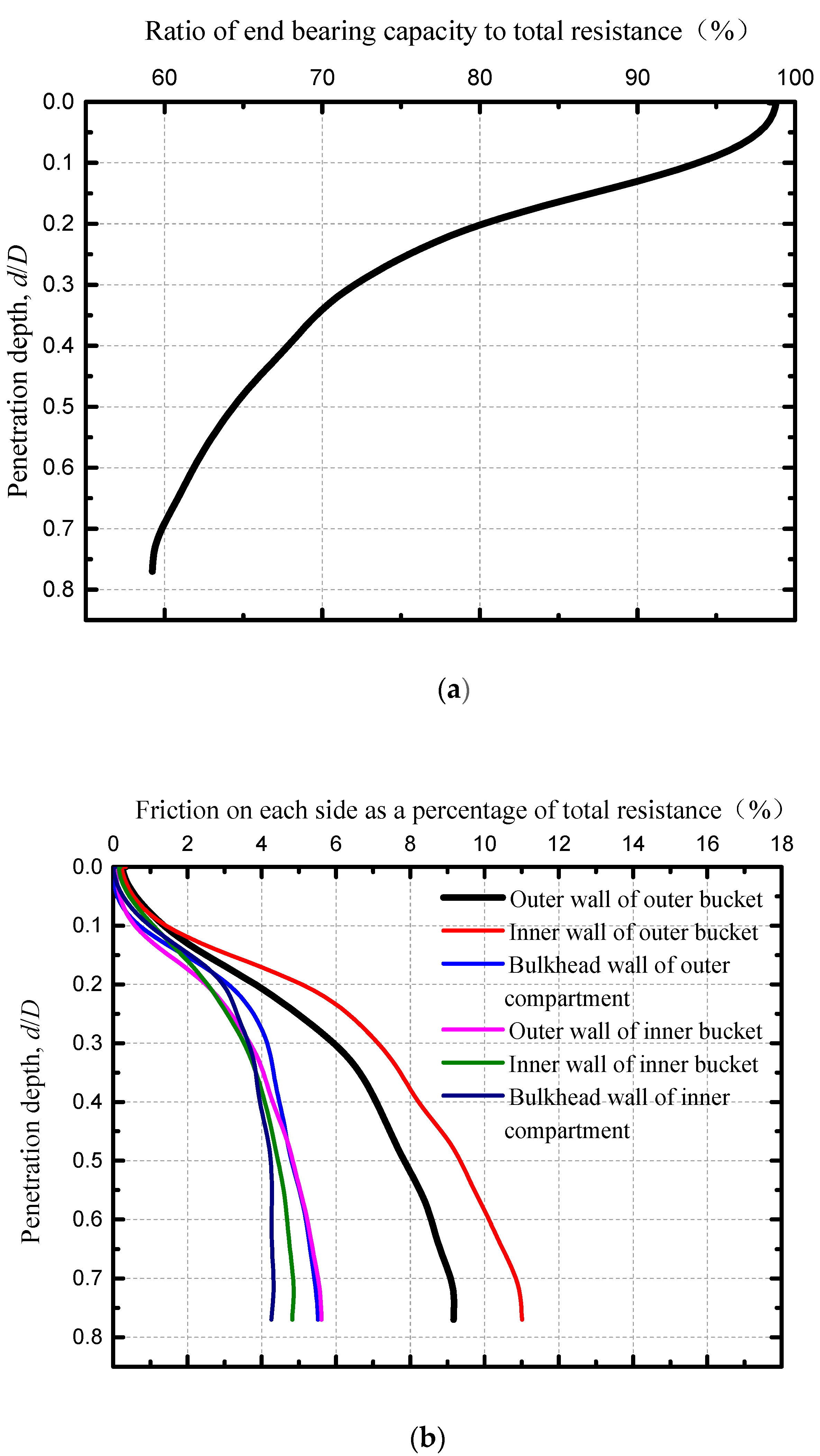
Although the bucket foundation studied in this paper incorporates the inner bucket and cruciform skirts, its penetration resistance can still be calculated according to the theory proposed by Houlsby and Byrne [
24]. The ratio of the individual resistance to the total resistance of the bucket foundation with the inner bucket and cruciform skirts is shown in
Figure 7.
It can be seen that the total resistance of the concrete thick-wall bucket foundation with the inner bucket and cruciform skirts mainly comes from the end bearing capacity. The ratio of the friction resistance to total penetration resistance increases with the penetration depth.
3.2.1. End Bearing Capacity
The equation for calculating the end bearing capacity at the bottom of the bucket is:
where
A is the bottom area. Therefore, the end bearing capacity coefficient
Nc can be derived as:
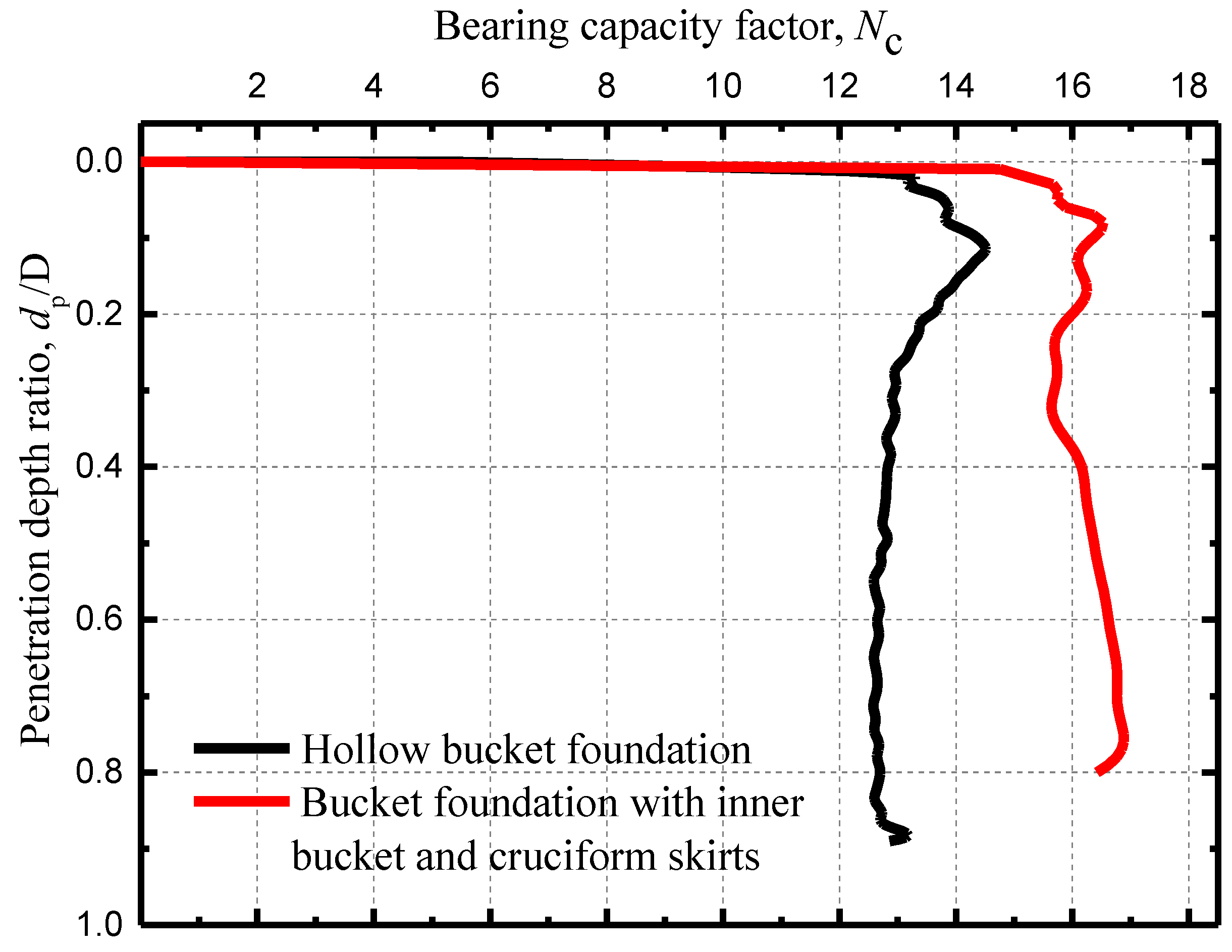
For the hollow bucket foundation and the bucket foundation with inner bucket and cruciform skirts, the corresponding change of the end bearing capacity coefficient
Nc with the penetration depth ratio is shown in
Figure 8.
It can be seen from
Figure 8 that the end bearing capacity coefficient of the hollow bucket foundation first increases with the penetration depth and then slightly decreases before stabilizing during further penetration. For bucket foundations with inner bucket and cruciform skirts, after the end bearing capacity coefficient increases and then slightly decreases with penetration depth, a slight increase occurs with penetration depth. For the investigated penetration depth, the end bearing capacity coefficient of the bucket foundation with inner bucket and cruciform skirts is obviously greater than that of the hollow bucket foundation.
3.2.2. Skirt Friction
According to Equation (5), the Equation for calculating skirt friction is shown as Equation (8):
where
L is the perimeter or width of each skirt. After conversion, the Equation for the adhesion coefficient α is:
The adhesion coefficient
α between the skirting board and the soil on both sides are calculated and the results for each skirt are shown in
Table 2.
The adhesion coefficient is generally considered as the inverse of the sensitivity of the soil, for which it is 0.25 in this case. However, it can be seen from the table that the value is much larger than 0.25 because the soil was partially remolded during the installation.
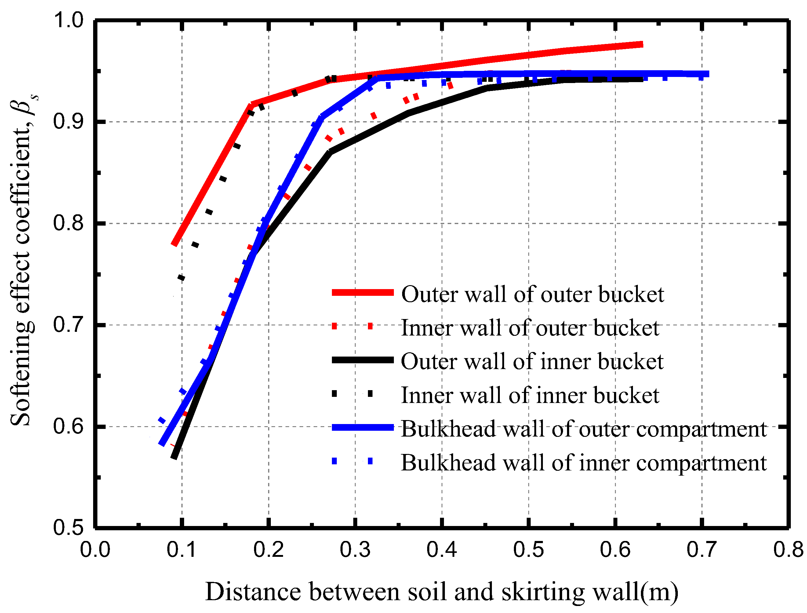
The adhesion coefficient α on the side of the skirting board is mainly determined by the degree of disturbance to the soil during the foundation installation, which can be expressed by the softening coefficient. However, for bucket foundations with inner bucket and cruciform skirts, the soil height in the compartment is too large due to the relatively small height of the foundation, which increases the adhesion coefficient.
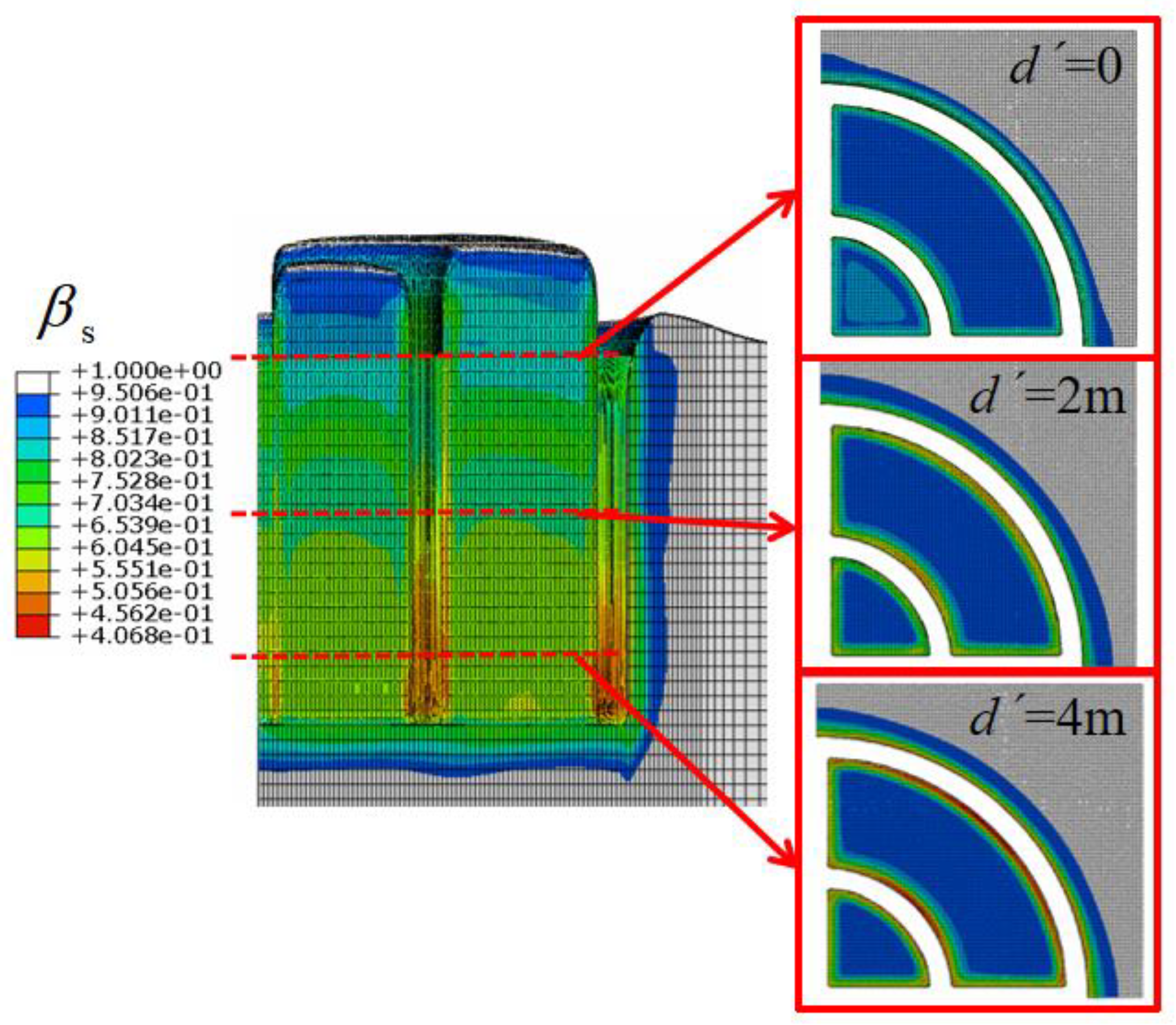
Taking the penetration depth ratio
d/
D = 0.5 as an example, the section view of the softening factor of the soil is shown in
Figure 9. The corresponding softening factor of the soil near different skirting boards is shown in
Figure 10.
It can be seen that the deeper the depth, the more severe the softening effect. Among the different skirting walls, most softening occurred in the outer wall of the inner bucket. However, due to the larger volume of soil in the outer compartment, the cohesion coefficient for the inner wall of the inner bucket is the largest while the cohesion coefficient of the outer wall of the outer bucket is the smallest.
3.3. The Optimal Inner Bucket Diameter
Through the analysis of soil flow and soil plug during the penetration, it is found that Din = D/2 is not the optimal configuration based on the analysis of the soil plug inside the foundation after penetration, though the contribution of the inner bucket to improve the overall rigidity of the foundation can be maximized. When the penetration depth is relatively large, the excessive difference in soil height between the inner and outer compartments will adversely affect the bearing capacity of the foundations.
It is feasible to vary the diameter of the inner bucket to affect the soil flow, so that a part of the soil that originally flowed into the outer compartment can be diverted to the inner compartment and maintained similar height of soil. It can not only solve the negative height of the soil in the inner compartment, but also reduce the height of the soil in the outer compartment. It is more conducive to the installation of the foundation to the predetermined buried depth and to achieving the designed bearing capacity.
Based on previous analysis, for large penetration depth, the side friction resistance of the unit volume of the soil in the compartment will play a decisive role in the flow of the soil and the final height of the soil in the compartment. In order to ensure similar soil height for the inner and outer compartments, the total lateral friction resistance acting on the unit volume of the soil should be equal in the inner and outer compartments. This is expressed in Equation (10):
where
Ffin and
Ffout are the total friction of the soil in the inner and outer compartments, and it has correlation to the coefficient of side friction, the average soil shear strength over the penetration depth, the bottom perimeter of the compartment, and the penetration depth, as shown in Equation (8);
Vin and
Vout are the soil volumes in the compartments, and they can be expressed by the bottom area of the compartments and the penetration depth. During the penetration of the bucket foundation with inner bucket and cruciform skirts, the penetration depth and the average soil shear strength are equal in the inner and outer compartments. Based on previous analyses, the side friction coefficients of the skirts are similar. For the convenience of analysis, it can be assumed that the side friction coefficients of the skirts are equal, and Equation (10) is expressed as:
It can be simplified to:
where
Lin and
Lout are the bottom perimeter of the inner and outer compartment; and
Sin and
Sout are the bottom area of the inner and outer compartments. The diameter of the inner bucket should be changed so that the inner and outer compartments satisfy Equation (12). Further calculation concluded that when
ain =
aout, the diameter of the inner bucket is about 5/8 of the total diameter (
Din = 5/8
D).
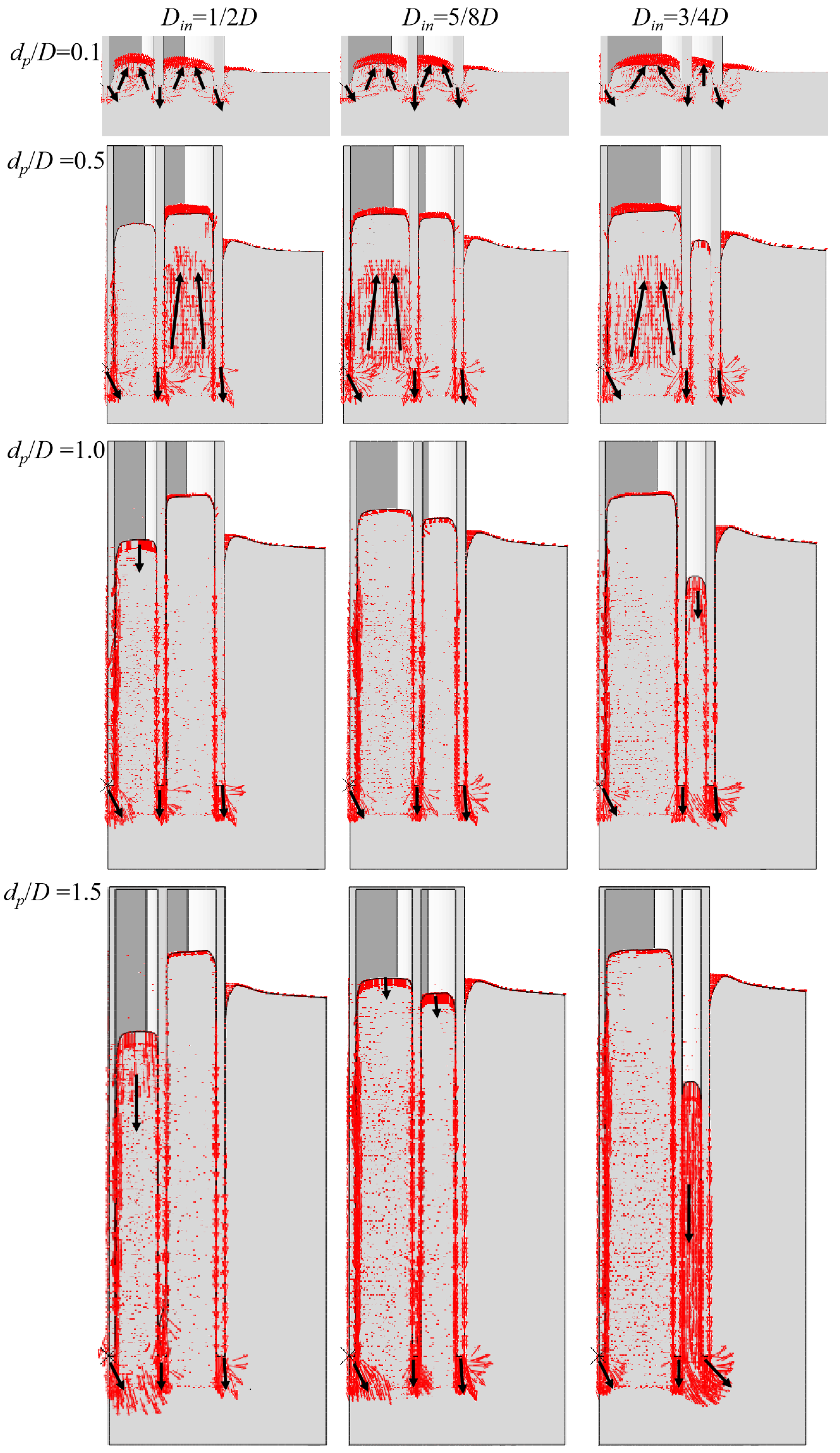
In addition, in order to better compare the influence of the diameter of internal cylinder on the soil flow and the soil surface in the inner and outer compartments during the foundation penetration process, it is necessary to calculate the penetration model when the diameter of the inner bucket is 3/4 of the total diameter.
When
Din = 1/2
D, 5/8
D, and 3/4
D, the average height of the soil surface and soil flow in the inner and outer compartments at different penetration depths (the 1-1’ section in
Figure 2b) are shown in
Figure 11. It can be seen that by changing the diameter of the inner bucket, the trend of soil flow changes significantly, and at the theoretically optimal inner bucket diameter (i.e.,
Din = 5/8
D), the inner and outer compartments can maintain similar soil surface. However, if the diameter of the inner cylinder is too large (i.e.,
Din = 3/4
D), the soil in the outer compartment will appear to have a negative height due to the excessive friction when the penetration depth is relatively large.
4. Conclusions
In this paper, a CEL large-deformation finite element model was established to simulate the penetration of the bucket foundation with inner bucket and cruciform skirts. The soil strain softening effect was considered. The soil flow, soil strength evolution, and penetration resistance during the installation were investigated. Then, the optimal inner bucket diameter was suggested based on the theoretical analysis and numerical results. The main findings are as follows:
(1) Due to the addition of inner bucket and cruciform skirts, the average height of the soil surface inside the inner or outer compartment is significantly higher than that of the hollow bucket foundation during shallow penetration. However, if the adopted diameter of the inner bucket is half the diameter of the outer bucket, the larger frictional resistance in the outer compartment hinders the upward flow of the soil with the increase of the penetration depth, while that in the inner compartment a large amount of soil is pushed downward. The significant difference of soil height between the outer and inner compartment will affect the post-installation bearing capacity of the foundation.
(2) The total resistance of a concrete thick-walled bucket foundation with the inner bucket and cruciform skirts is equal to the sum of the friction resistance of all skirts and the end bearing capacity. The end bearing capacity coefficient of the bucket foundation with the inner bucket and cruciform skirts was significantly larger than that of the hollow bucket foundation. Meanwhile, the end bearing capacity accounts for a large proportion of the total resistance. Due to the partial remolding of the soil during the penetration, the friction coefficient for the bucket skirt was larger than the inverse of the sensitivity of the soil.
(3) The optimal inner bucket diameter is equal to 5/8 of the outer diameter obtained from the theoretical analysis and numerical results. Under the circumstances, the height of the soil surface in the inner and outer compartments is almost equal because the friction resistance acting on the unit volume of the soil in the inner compartment is equal to that in the outer compartment. It can be seen that the trend of soil flow is effectively varied by expanding the ratio of the diameter of the inner bucket to the outer diameter of the bucket foundation.
The findings add further value to the application of multi-compartment foundations such as bucket foundations with internal cylindrical and cruciform skirts. Further investigation is necessary to study the penetration of the bucket foundation, equipped with an inner bucket and cruciform skirts, into sandy soil, while taking into account the staged installation and variation in pore pressure.


 ,
, 


