
Borehole Instability in Decomposed Granite Seabed for Rock-Socketed Monopiles during “Drive-Drill-Drive” Construction Process: A Case Study


Abstract
1. Introduction
2. Background
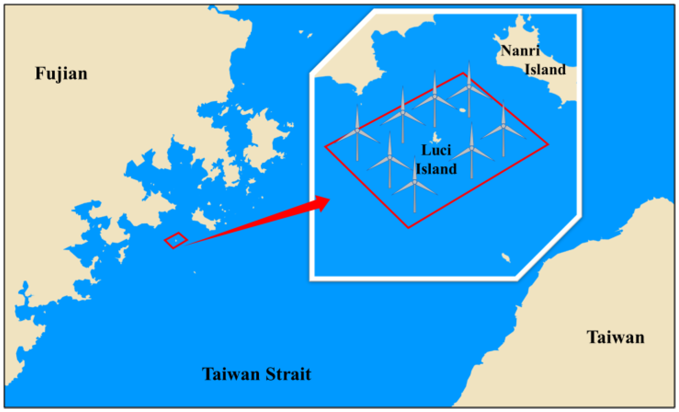
2.1. Project Information
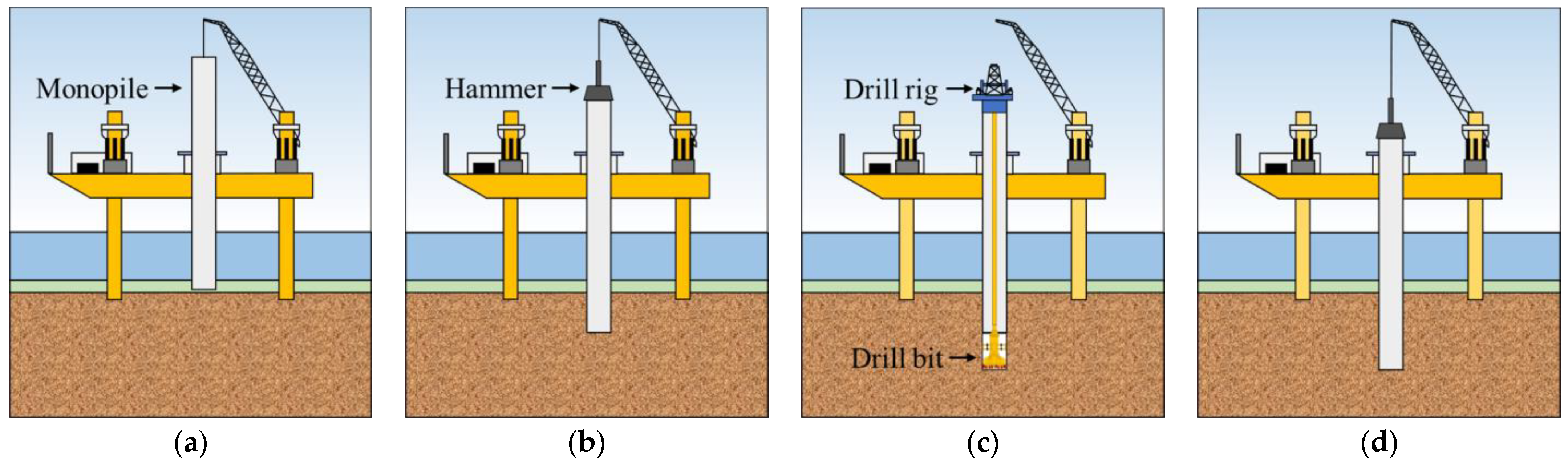
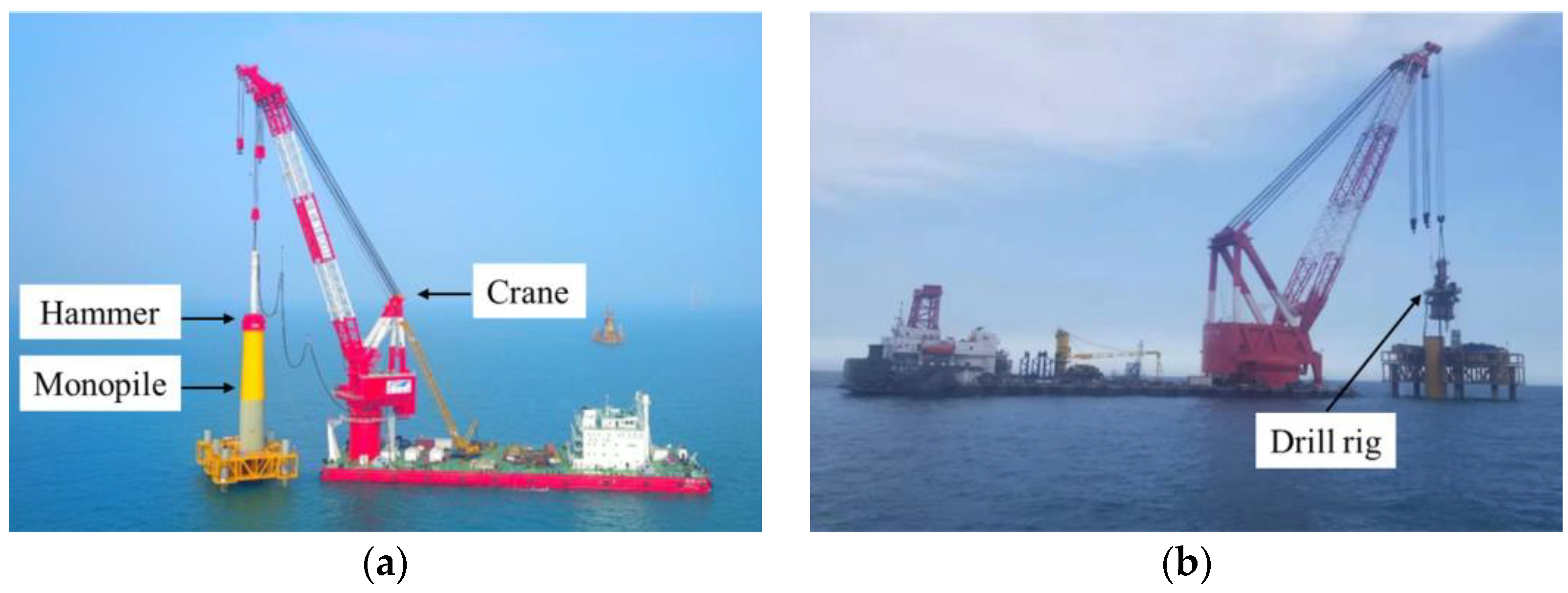
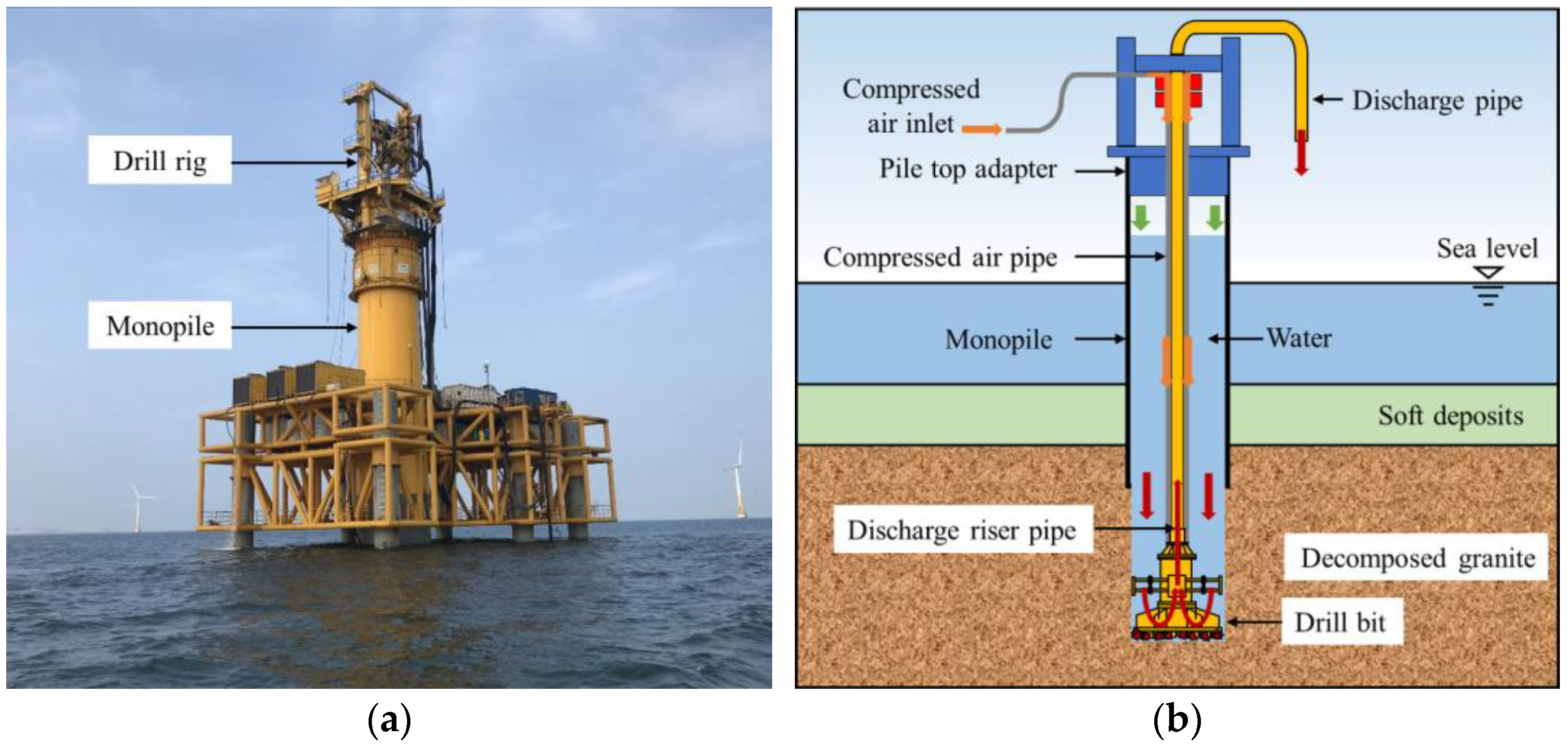
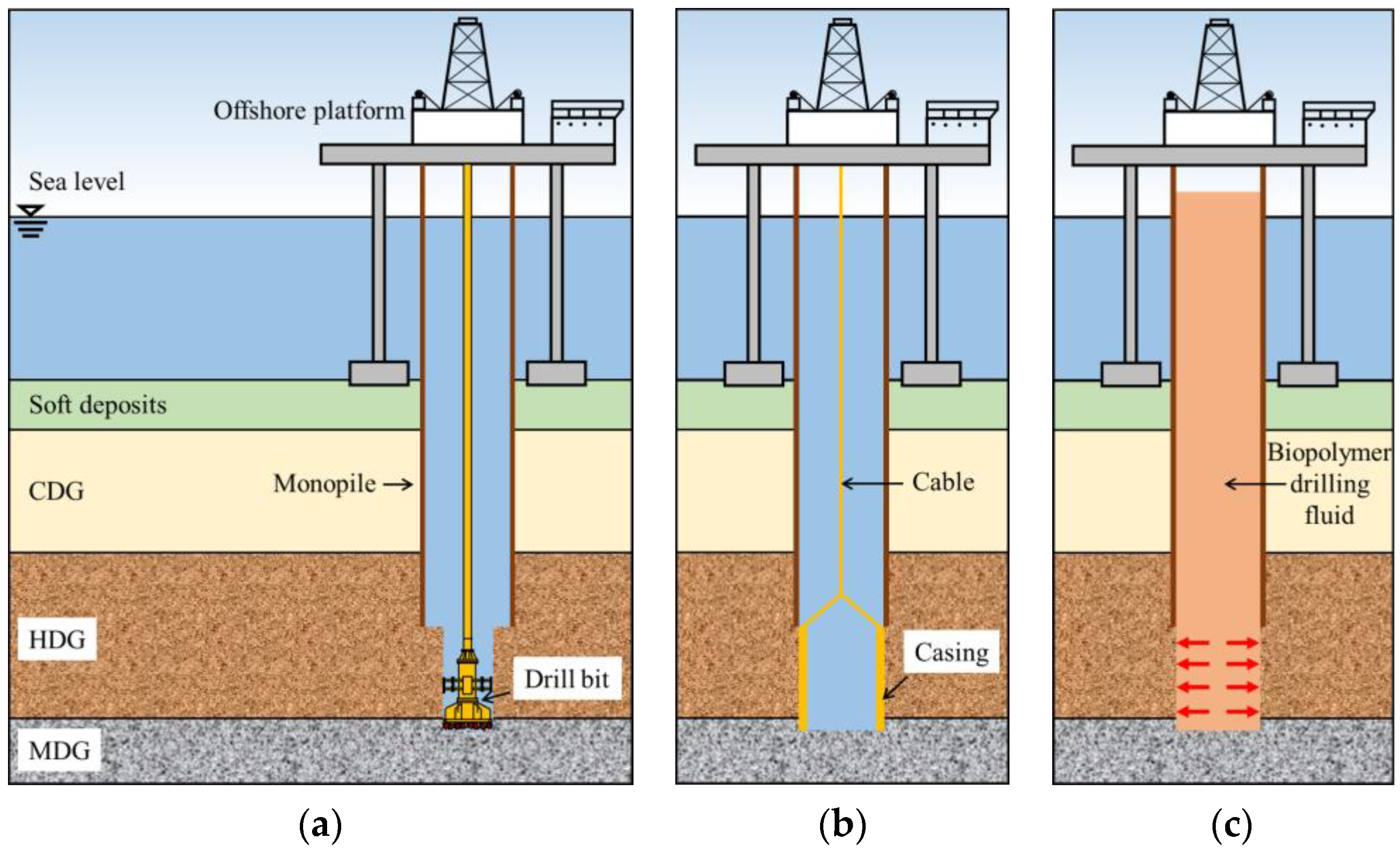
2.2. Construction Technology
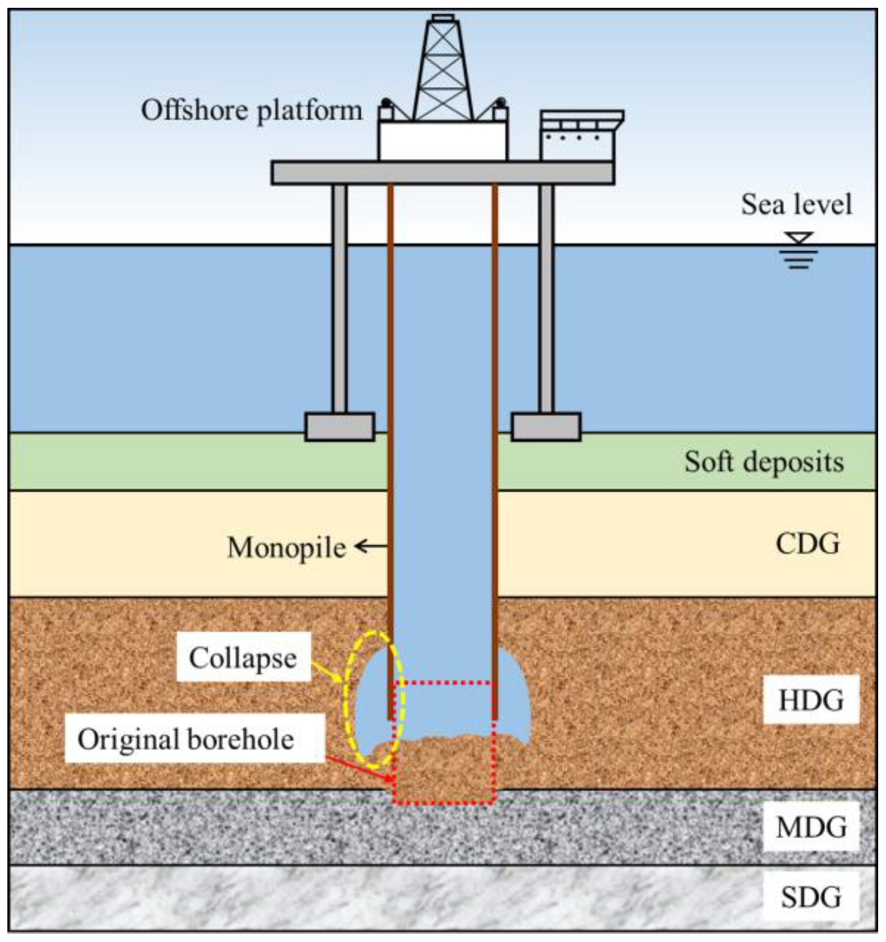
2.3. Borehole Instability
2.4. Typical Borehole Collapse Cases
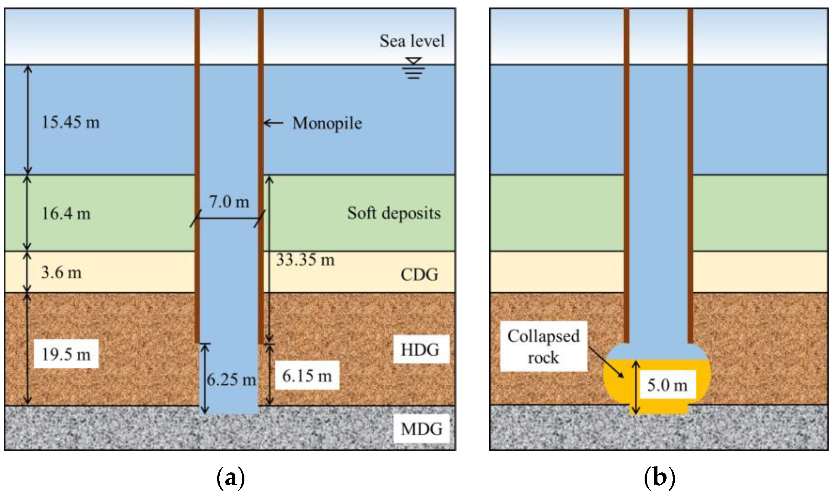
2.4.1. Case 1
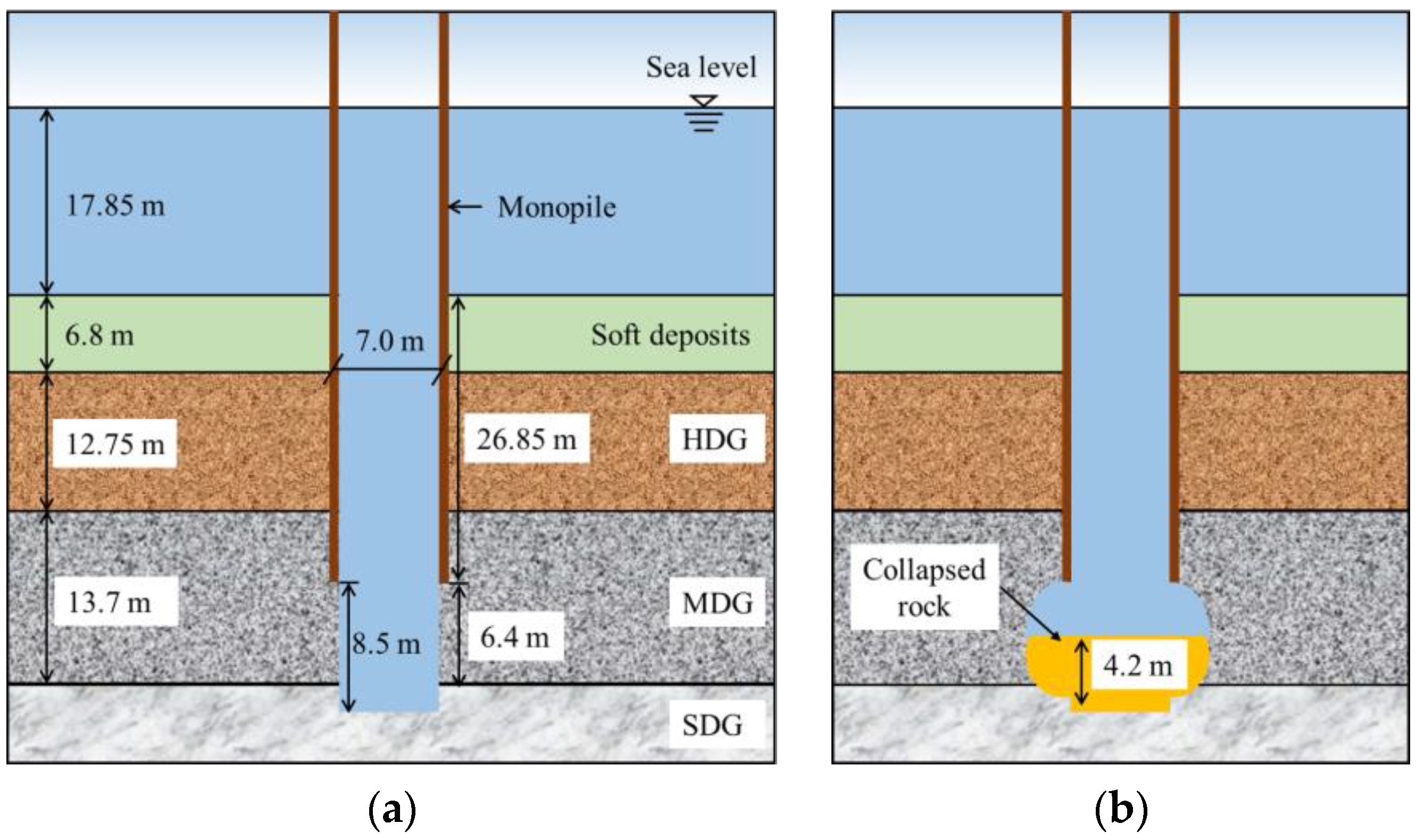
2.4.2. Case 2
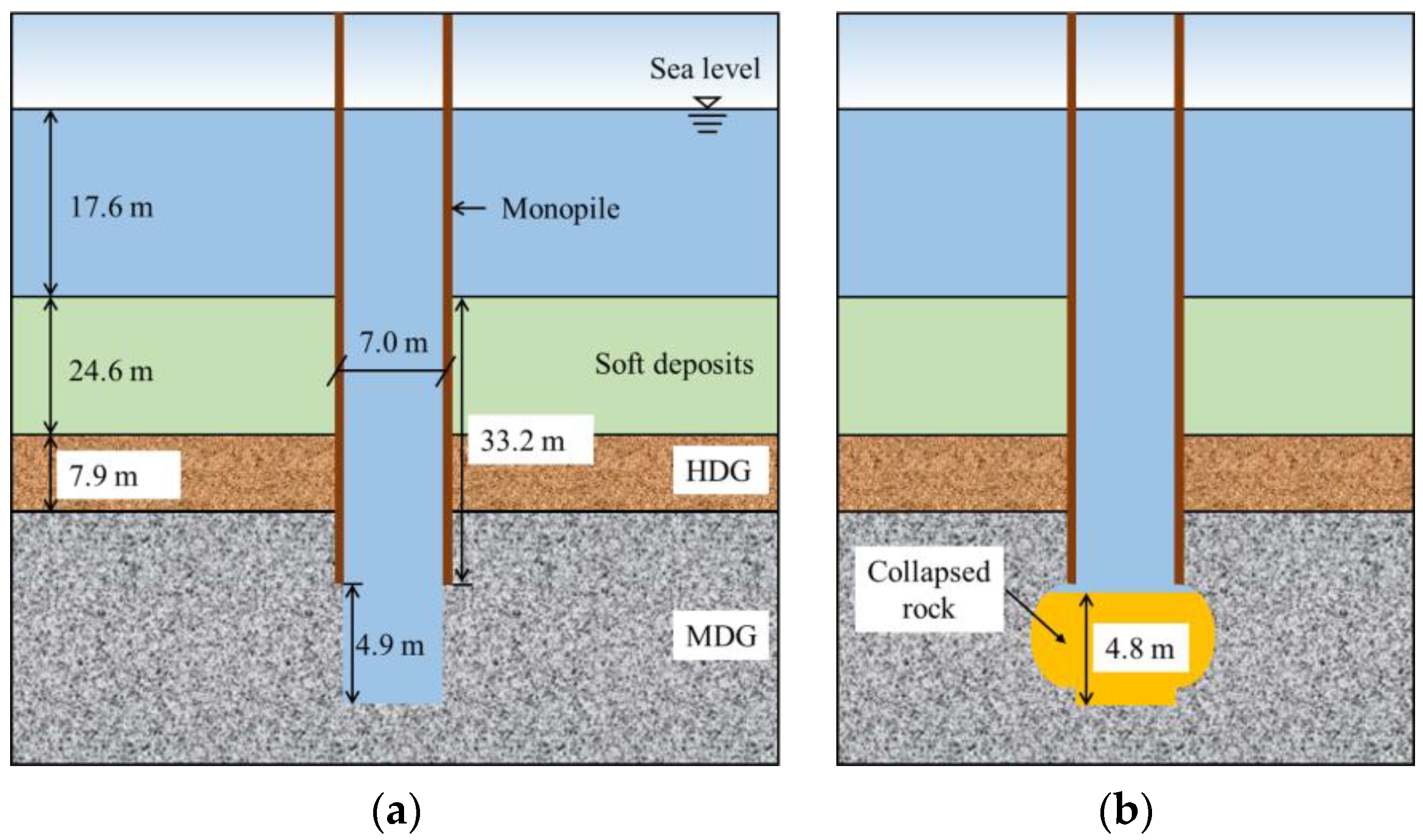
2.4.3. Case 3
3. Methodology
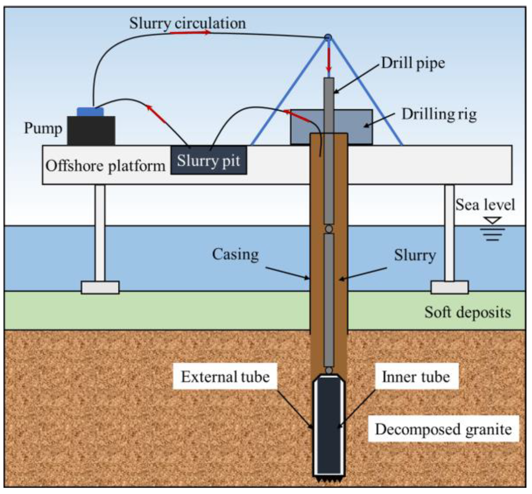
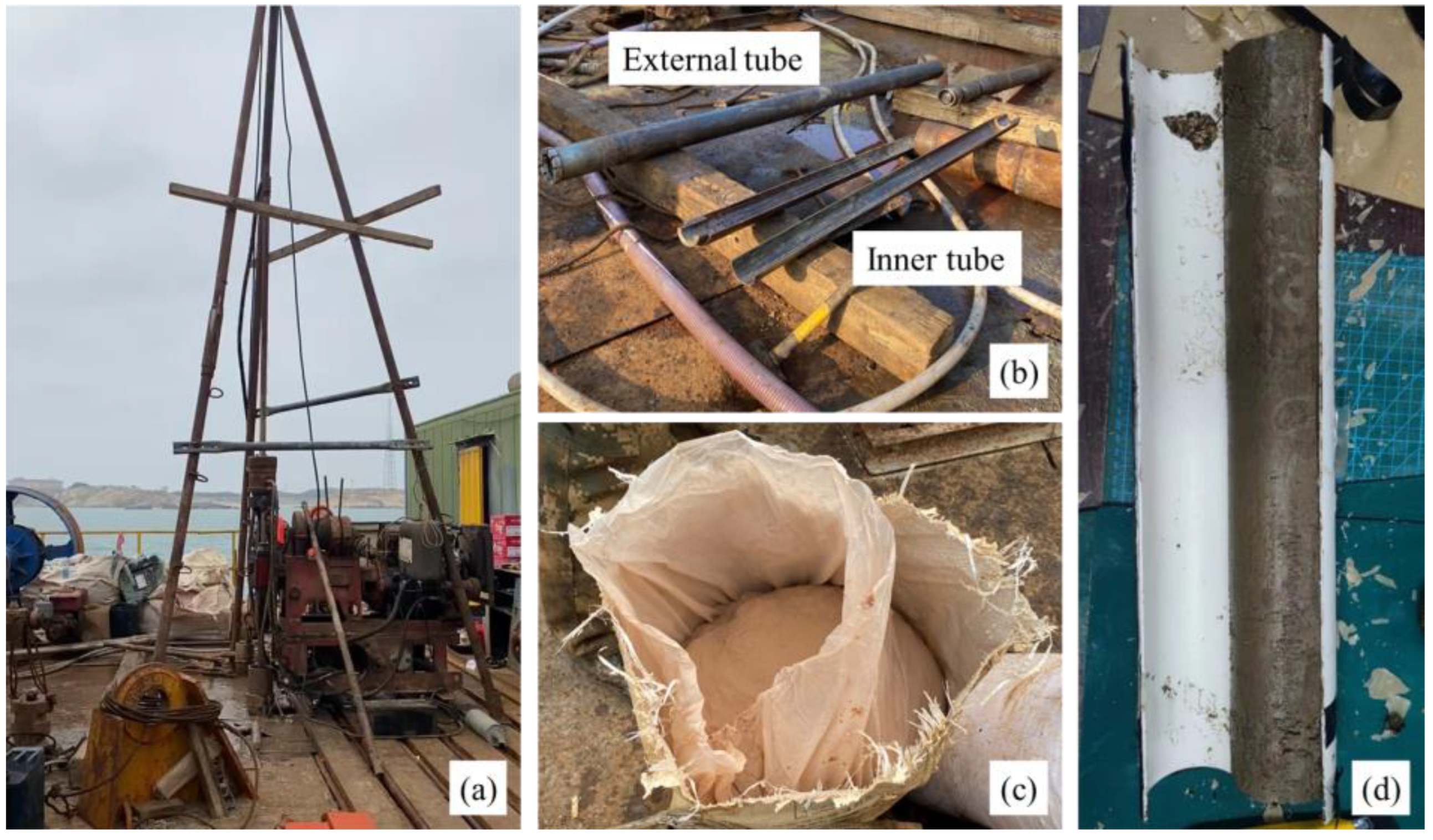
3.1. Sampling Method
3.2. In Situ Tests
3.3. Laboratory Tests
4. Results and Discussion
4.1. Physical and Mechanical Properties of Decomposed Granite
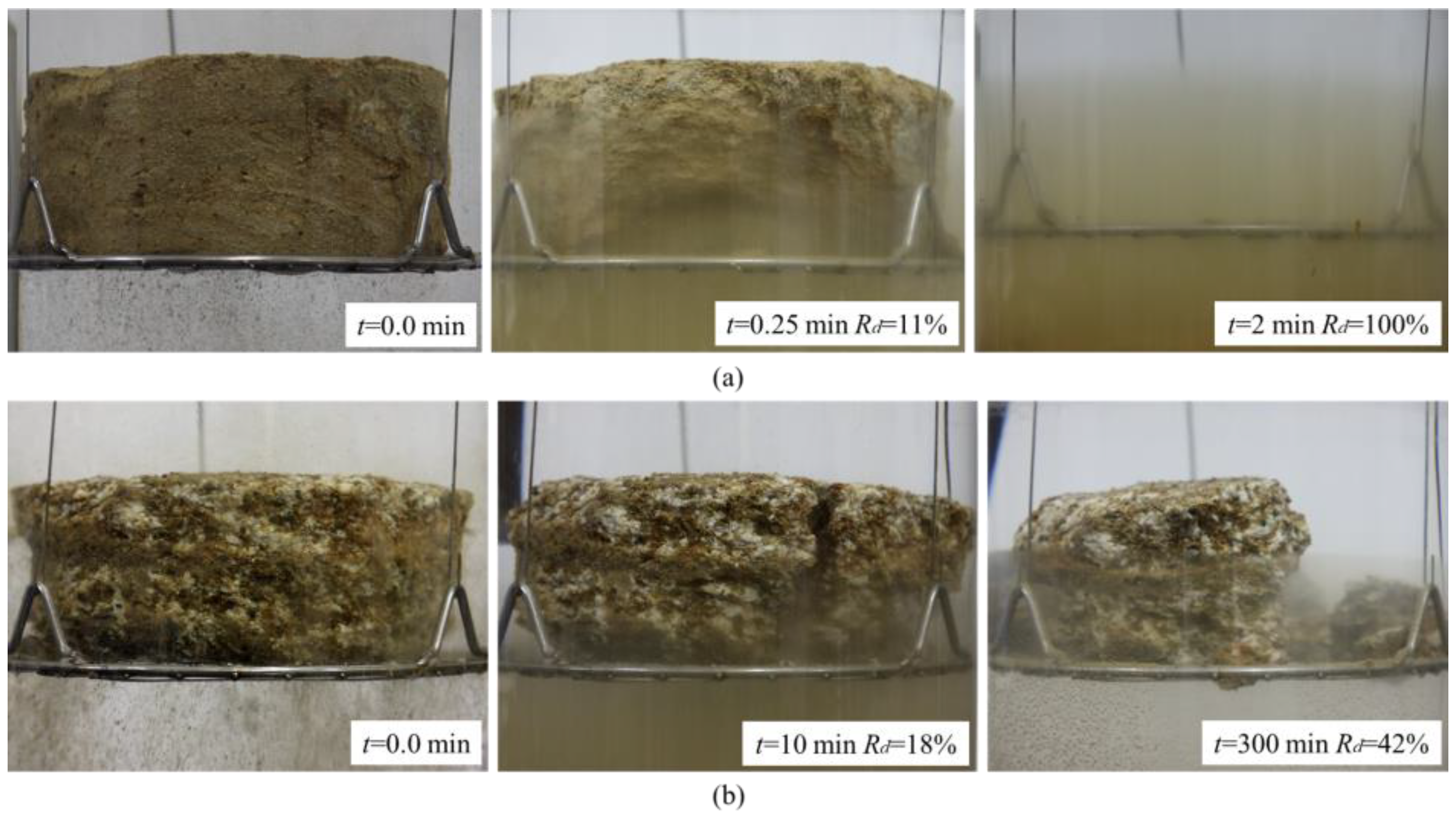
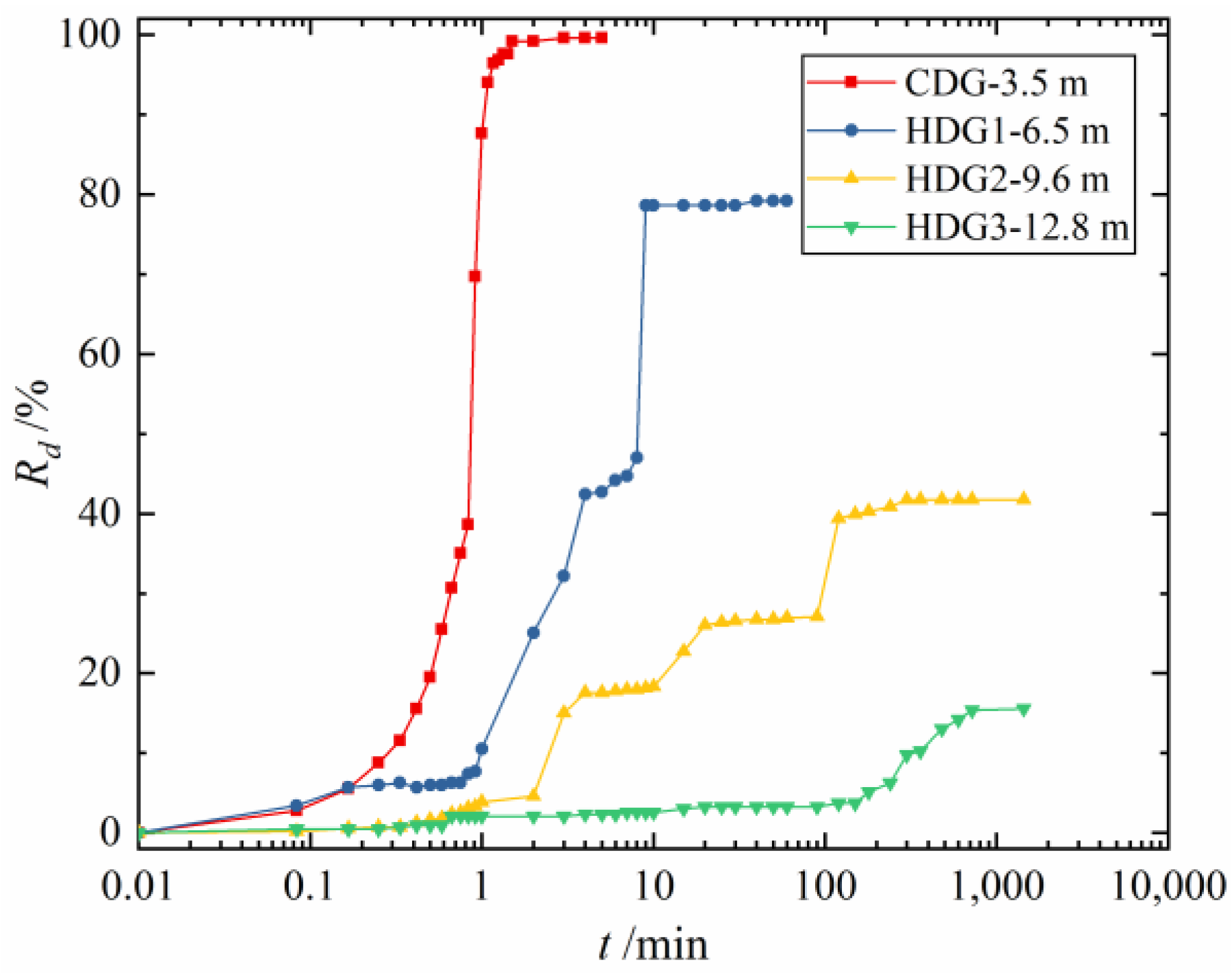
4.2. Disintergration Properties of Decomposed Granite
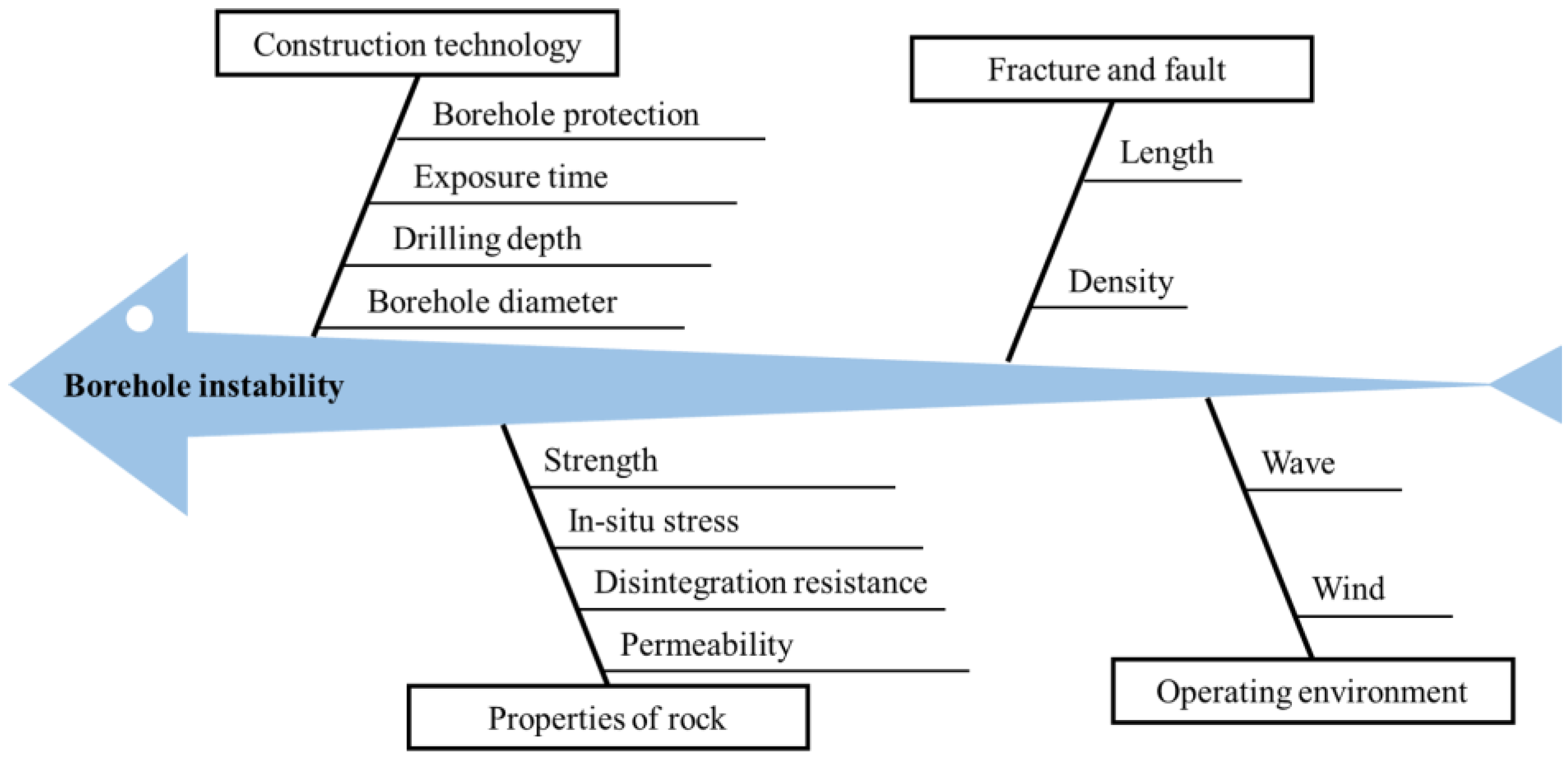
4.3. Causes for Borehole Instability
4.4. Judgement of the Possibility of Borehole Instability
4.5. Improvement Measures to Prevent Borehole Instability
- (1)
- Using a smaller diameter drilling rig during drilling. In this case, the range of exposed soil is reduced, and considering the soil arching effect, the possibility of borehole instability is significantly reduced. Even if borehole instability occurs, the buffer effect provided by the distance between the borehole wall and the monopile can prevent pile running. Additionally, constructing a hollow cylindrical structure of soil within the monopile can also significantly reduce pile driving resistance.
- (2)
- Using a casing that can be lifted and lowered freely. After drilling is completed, the casing can be lowered to protect the borehole wall and then lifted back up after the next step of pile driving is completed. This method can provide support to the borehole wall to prevent borehole instability.
- (3)
- Using biopolymer drilling fluid during drilling to form a filter cake on the borehole wall. This can prevent decomposed granite from directly contacting seawater, avoiding disintegration. It can also exert static water pressure on the borehole wall to counteract the stress release caused by excavation and maintain borehole stability. Compared with traditional slurry, biopolymer drilling fluid causes minimal pollution to the marine environment, but its disadvantage is its high cost.
5. Conclusions
- (1)
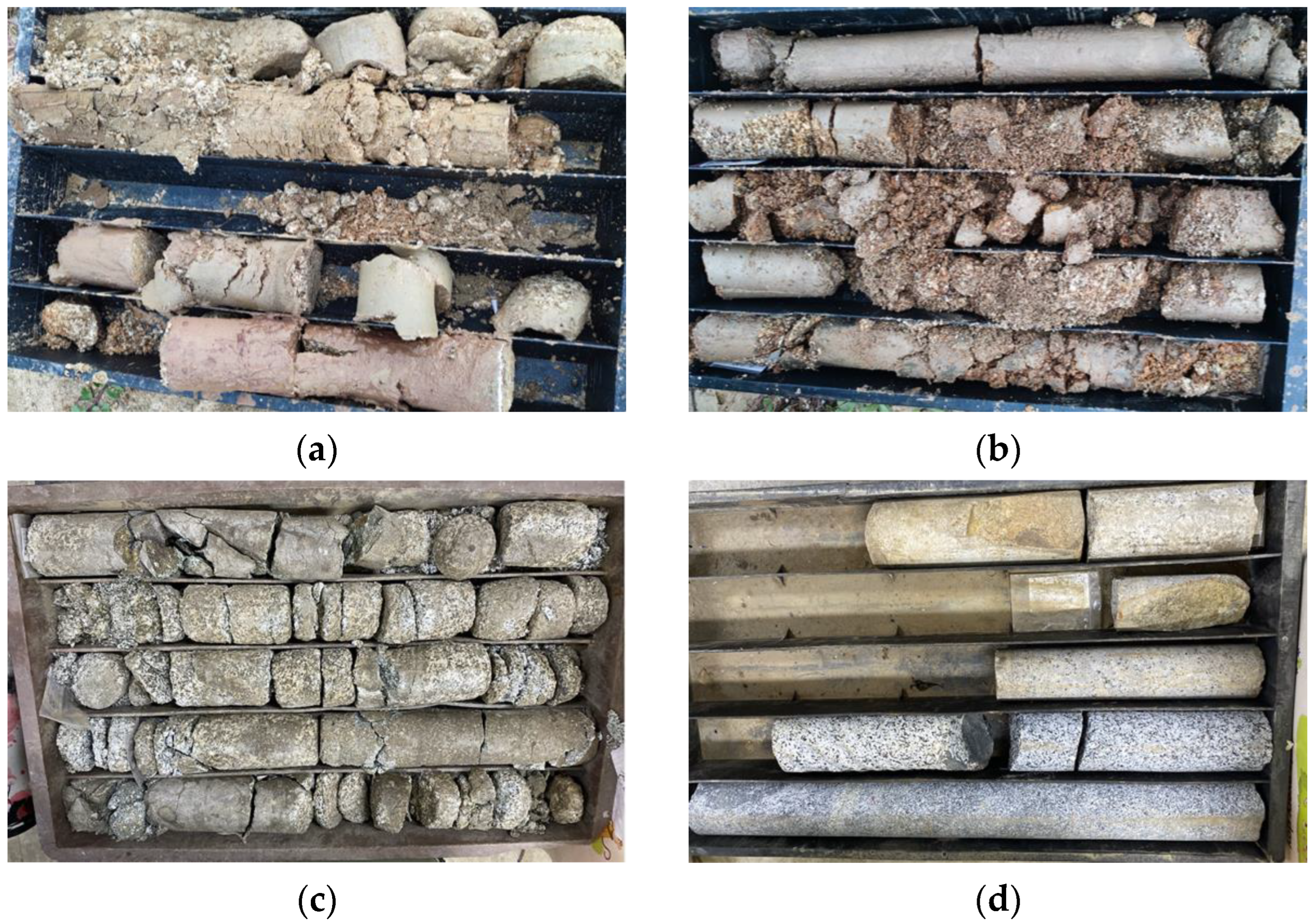
- The results of the sampling operation demonstrate that employing a double-tube rotary sampler with biopolymer drilling fluid significantly minimizes disturbance to decomposed granite, enabling the acquisition of complete samples. A series of in situ and laboratory tests revealed an increase in the weathering degree of granite from SDG to MDG, HDG, and CDG, while mechanical strength and integrity declined considerably. These four types of decomposed granite can be effectively classified based on apparent characteristics, in situ tests, and laboratory tests.
- (2)
- The long window period between drilling and monopile driving operations, the insufficient soil shear strength, and the lack of hole wall protection are the main causes of borehole instability. Due to HDG’s insufficient strength and the highly fragmented structure of MDG, hole collapse predominantly occurs within CDG and MDG strata. The water-immersion disintegration properties of HDG exacerbate the collapse rate in HDG strata. Additional factors, such as large pile foundation dimensions, geological fractures or faults, and adverse construction environments, may worsen this issue.
- (3)
- The occurrence of hole collapse can be comprehensively determined by considering factors such as stratum type, soil exposure range, and exposure duration. The key to preventing hole wall instability lies in reducing exposed soil range and duration or implementing suitable retaining wall measures. Drilling smaller holes has proven effective in engineering practice. Employing casing or plant-based drilling fluid for hole wall protection may also be considered a potential improvement measure.
Author Contributions
Funding
Institutional Review Board Statement
Informed Consent Statement
Data Availability Statement
Conflicts of Interest
References
- Global Wind Energy Council. Global Wind Report 2022; Global Wind Energy Council: Brussels, Belgium, 2022. [Google Scholar]
- Zhang, J.; Wang, H. Development of offshore wind power and foundation technology for offshore wind turbines in China. Ocean Eng. 2022, 266, 113256. [Google Scholar] [CrossRef]
- Gasch, R.; Twele, J. Wind Power Plants: Fundamentals, Design, Construction and Operation; Springer Science & Business Media: Berlin/Heidelberg, Germany, 2011. [Google Scholar]
- Wu, X.; Hu, Y.; Li, Y.; Yang, J.; Duan, L.; Wang, T.; Adcock, T.; Jiang, Z.; Gao, Z.; Lin, Z. Foundations of offshore wind turbines: A review. Renew. Sustain. Energy Rev. 2019, 104, 379–393. [Google Scholar] [CrossRef]
- Byrne, B.W.; Houlsby, G.T.; Burd, H.J.; Gavin, K.G.; Igoe, D.J.; Jardine, R.J.; Martin, C.M.; McAdam, R.A.; Potts, D.M.; Taborda, D.M. PISA design model for monopiles for offshore wind turbines: Application to a stiff glacial clay till. Géotechnique 2020, 70, 1030–1047. [Google Scholar] [CrossRef]
- Byrne, B.W.; McAdam, R.A.; Burd, H.J.; Beuckelaers, W.J.; Gavin, K.G.; Houlsby, G.T.; Igoe, D.J.; Jardine, R.J.; Martin, C.M.; Muir Wood, A. Monotonic laterally loaded pile testing in a stiff glacial clay till at Cowden. Géotechnique 2020, 70, 970–985. [Google Scholar] [CrossRef]
- Fan, S.; Bienen, B.; Randolph, M.F. Effects of monopile installation on subsequent lateral response in sand. I: Pile installation. J. Geotech. Geoenviron. Eng. 2021, 147, 04021021. [Google Scholar] [CrossRef]
- Chiu, C.; Ng, C.W. Relationships between chemical weathering indices and physical and mechanical properties of decomposed granite. Eng. Geol. 2014, 179, 76–89. [Google Scholar] [CrossRef]
- Liu, X.; Zhang, X.; Kong, L.; Li, X.; Wang, G. Effect of cementation on the small-strain stiffness of granite residual soil. Soils Found. 2021, 61, 520–532. [Google Scholar] [CrossRef]
- Duan, K.; Wu, W.; Kwok, C.Y. Discrete element modelling of stress-induced instability of directional drilling boreholes in anisotropic rock. Tunn. Undergr. Space Technol. 2018, 81, 55–67. [Google Scholar] [CrossRef]
- Fink, J. Petroleum Engineer’s Guide to Oil Field Chemicals and Fluids; Gulf Professional Publishing: Houston, TX, USA, 2021. [Google Scholar]
- Haimson, B. Micromechanisms of borehole instability leading to breakouts in rocks. Int. J. Rock Mech. Min. Sci. 2007, 44, 157–173. [Google Scholar] [CrossRef]
- Lan, H.; Moore, I.D. Experimental investigation examining influence of pump rates on horizontal borehole stability in sand. Tunn. Undergr. Space Technol. 2022, 127, 104608. [Google Scholar] [CrossRef]
- Abdulhadi, N.O.; Germaine, J.T.; Whittle, A.J. Experimental study of wellbore instability in clays. J. Geotech. Geoenviron. Eng. 2011, 137, 766–776. [Google Scholar] [CrossRef]
- Castillo, J.G.; Nagula, S.; Schallück, C.; Grabe, J. Numerical Simulation of Drive-Drill-Drive Techniques for Open-Ended Pile Installations. In Recent Advancements in Civil Engineering: Select Proceedings of ACE 2020; Springer: Berlin/Heidelberg, Germany, 2022; pp. 539–548. [Google Scholar]
- Li, L.; Ru, D.; Li, K.; Yishan, W. Research and Application of Reverse Circulation Drilling Technology. In Proceedings of the International Oil & Gas Conference and Exhibition in China, Beijing, China, 5–7 December 2006. [Google Scholar]
- Viana da Fonseca, A.; Pineda, J. Getting high-quality samples in ‘sensitive’soils for advanced laboratory tests. Innov. Infrastruct. Solut. 2017, 2, 34. [Google Scholar] [CrossRef]
- Mayne, P.W.; Christopher, B.R.; DeJong, J. Manual on Subsurface Investigations; National Highway Institute Publication No. FHWA NHI-01-031; Federal Highway Administration: Washington, DC, USA, 2001.
- Xia, S.; Zhang, L.; Davletshin, A.; Li, Z.; You, J.; Tan, S. Application of polysaccharide biopolymer in petroleum recovery. Polymers 2020, 12, 1860. [Google Scholar] [CrossRef] [PubMed]
- ASTM D2487; Standard Practice for Classification of Soils for Engineering Purposes. ASTM International (ASTM): West Conshohocken, PA, USA, 2011.
- Hencher, S.R.; Martin, R.P. The Description and Classification of Weathered Rocks in Hong Kong for Engineering Purposes. In Proceedings of the 7th South-East Asian Geotechnical Conference, Hong Kong, China, 22–26 November 1982; pp. 125–142. [Google Scholar]
- Ng, C.W.; Yau, T.L.; Li, J.H.; Tang, W.H. Side resistance of large diameter bored piles socketed into decomposed rocks. J. Geotech. Geoenviron. Eng. 2001, 127, 642–657. [Google Scholar] [CrossRef]
- Li, Z.; Lin, W.; Ye, J.; Chen, Y.; Bian, X.; Gao, F. Soil movement mechanism associated with arching effect in a multi-strutted excavation in soft clay. Tunn. Undergr. Space Technol. 2021, 110, 103816. [Google Scholar] [CrossRef]


| Type | Grade | General Characteristics | Typical Characteristics |
|---|---|---|---|
| CDG | Ⅴ | Gray-yellow with brown yellow | High content of clay minerals |
| Destroyed completely, soil like | Can be crumbled by hand | ||
| HDG | Ⅳ | Gray-white with black | Mainly quartz and feldspar |
| Original rock texture preserved, sandy soil like | Can be broken by hand | ||
| MDG | Ⅲ | Brown yellow | Part of feldspar is weathered |
| Clear structure of parent rocks, clastic blocks | Not easily broken by hand, easily broken by hammer | ||
| SDG | Ⅱ | Gray-white with black | Mainly quartz, feldspar, and mica |
| Distinct structure of parent rocks, column-like | Cannot usually be broken by hand, not easily broken by hammer |
| Parameter | CDG | HDG | MDG | SDG |
|---|---|---|---|---|
| ρn/(g/cm3) | 1.83~2.04 | 1.87~2.21 | / | / |
| ρd/(g/cm3) | 1.50~1.73 | 1.46~1.92 | 2.68~2.72 | 2.62~2.81 |
| e | 0.552~0.814 | 0.397~0.850 | / | / |
| ω/% | 17.7~29.9 | 14.3~30.6 | / | / |
| Gs | 2.69~2.72 | 2.68~2.72 | / | / |
| av0.1~0.2/MPa−1 | 0.30~0.54 | 0.23~0.28 | / | / |
| Es1~2/MPa | 3.35~5.49 | 5.53~11.61 | / | / |
| Ee/GPa | / | / | / | 16.8~51.9 |
| c/kPa | 21.3~25.3 | 18.3~23.4 | 205.9~6900 | / |
| φ/° | 27.4~28.8 | 28.4~35.2 | 34.9~52.4 | / |
| Is/MPa | / | / | 0.33~0.68 | / |
| R/MPa | / | / | 5.38~18.20 | 30.63~107.20 |
| k/(10−6 cm/s) | 58.2~87.5 | 61.2~426.0 | / | / |
| Vs/(m/s) | 311~346 | 316~495 | 447~681 | 610~936 |
| ρ/(Ω·m) | 1.46~1.91 | 2.18~11.36 | 10.73~44.26 | 23.66~152.55 |
| N | 33~47 | 55~67 | / | / |
Disclaimer/Publisher’s Note: The statements, opinions and data contained in all publications are solely those of the individual author(s) and contributor(s) and not of MDPI and/or the editor(s). MDPI and/or the editor(s) disclaim responsibility for any injury to people or property resulting from any ideas, methods, instructions or products referred to in the content. |
© 2023 by the authors. Licensee MDPI, Basel, Switzerland. This article is an open access article distributed under the terms and conditions of the Creative Commons Attribution (CC BY) license (https://creativecommons.org/licenses/by/4.0/).
Share and Cite
Sun, B.; Zhang, Q.; Zhu, W.; Leng, J.; Ye, G. Borehole Instability in Decomposed Granite Seabed for Rock-Socketed Monopiles during “Drive-Drill-Drive” Construction Process: A Case Study. J. Mar. Sci. Eng. 2023, 11, 990. https://doi.org/10.3390/jmse11050990
Sun B, Zhang Q, Zhu W, Leng J, Ye G. Borehole Instability in Decomposed Granite Seabed for Rock-Socketed Monopiles during “Drive-Drill-Drive” Construction Process: A Case Study. Journal of Marine Science and Engineering. 2023; 11(5):990. https://doi.org/10.3390/jmse11050990
Chicago/Turabian StyleSun, Bo, Qi Zhang, Wenxuan Zhu, Jian Leng, and Guanlin Ye. 2023. "Borehole Instability in Decomposed Granite Seabed for Rock-Socketed Monopiles during “Drive-Drill-Drive” Construction Process: A Case Study" Journal of Marine Science and Engineering 11, no. 5: 990. https://doi.org/10.3390/jmse11050990
APA StyleSun, B., Zhang, Q., Zhu, W., Leng, J., & Ye, G. (2023). Borehole Instability in Decomposed Granite Seabed for Rock-Socketed Monopiles during “Drive-Drill-Drive” Construction Process: A Case Study. Journal of Marine Science and Engineering, 11(5), 990. https://doi.org/10.3390/jmse11050990