Article

Development and Influence of Pore Pressure around a Bucket Foundation in Silty Soil

1
Key Laboratory of Concrete and Prestressed Concrete Structure of Ministry of Education, Southeast University, Nanjing 210096, China
2
Shanghai Investigation, Design & Research Institute Co., Ltd., Shanghai 200335, China
*
Author to whom correspondence should be addressed.
J. Mar. Sci. Eng. 2022, 10(12), 2020; https://doi.org/10.3390/jmse10122020
Submission received: 16 November 2022 / Revised: 9 December 2022 / Accepted: 14 December 2022 / Published: 17 December 2022
(This article belongs to the Special Issue New Challenges in Offshore Geotechnical Engineering Developments)

Abstract

:
Silty soil is common in the seabed of eastern coastal areas of China. The behaviors of the silty soil and a bucket foundation installed within it need more study. In this work, model tests of a bucket foundation in silty soil were performed. The development of the excess pore water pressures in the different positions around the bucket was measured. Different loading conditions, with a change in the horizontal cyclic load amplitude ratio, horizontal cyclic frequency, and vertical load ratio, were considered. The effects of the pore water pressure on the shear strength of the soil around the bucket and the horizontal bearing capacity of the bucket foundation were investigated. The results show that the normalized pore water pressures close to the bucket wall at depths between 0.1 L and 0.3 L exhibit distinct change under the cyclic load. Consistent with the distribution of the pore water pressure, the degradation of the undrained shear strength is more obvious with a greater load amplitude ratio, a greater load frequency, and a smaller vertical load. The degradation rate of the static horizontal ultimate bearing capacity is in a range of 1.57% to 14.90%, under different loading conditions.

1. Introduction

Offshore wind energy is considered to be one of the most important renewable energy resources due to its rich reserve, wide distribution, and freedom from pollution. In recent years, a number of wind farms have been planned and constructed in the eastern coastal areas of China. In this region, silty soil is widely distributed in the seabed. The physical properties and mechanical behaviors of silty soils are quite different from those of clay and sand. Using wave tank tests, Clukey et al. [1] found that silts were more susceptible to wave-induced liquefaction due to the build-up of excess pore-water pressures. The accumulation of the pore pressure in silty soil may affect the bearing capacity of the foundation of the wind turbine, which will bring challenges to the design and operation of wind farms [2,3].
A suction bucket foundation can be installed into the seabed with self-weight and suction pressure, which is thought to be a cost-effective fountain type due to the speed of installation and reduction in material costs comparing with other commonly used foundations. The cyclic lateral loadings induced by wind, waves, and currents in a marine environment may cause the accumulation of excess pore pressure in the soil around the bucket foundation, which may result in a decrease in the effective stress of the soil. Consequently, the bearing capacity of the suction bucket foundation will be decreased.
The development of pore pressure in clay under cyclic loads has been extensively studied over the past few decades. Several numerical models have been proposed to study the oscillatory and residual soil response under vertical wave loading by solving the Biot equation [4,5,6]. The development of pore water pressure and a liquefaction zone around the monopile in the seabed can be predicted and analyzed. In recent years, the soil–foundation interaction under vertical cyclic loads was also investigated by some researchers. Shen [7] proposed a finite element model of a suction anchor in the porous seabed subjected to cyclic uplifting loads. The results indicated that soil properties and the cyclic loading condition affected the accumulation of pore pressure around the suction anchor and the degradation of the anchor–soil frictional resistance was estimated. Some researchers [8,9,10] investigated the influence of the axial cyclic loading on the behavior of the foundation, considering the installation process. For the suction bucket foundation, the suction during installation may lead to seepage and cause a reduction in the soil strength. Some centrifuge tests [11,12], small scale tests [13,14], and numerical simulations [10,15,16] were also conducted to study the bearing capacity of the bucket foundation. In the previous work, more attention was paid to the influence of the L/D ratio (L is height and D is diameter of the bucket), loading regime, soil properties, and installation process on the horizontal bearing capacity of the foundation. Lazcano et al. [17] proposed a method to calculate the pore water pressure considering the in situ effective vertical stress, static shear stress, cyclic shear stress, and void ratio, and it was implemented to a numerical model, which could be used to calculate the bearing capacity of a shallow foundation under cyclic loading. Previous researchers also paid attention to the effect of cyclic loading on the soil strength degradation and bearing capacity degradation separately. Hodder et al. [18] proposed an analytical framework to estimate the degradation of undrained shear strength due to gross disturbance by a T-bar penetrometer. Ajmera et al. [19] investigated the effect of plasticity characteristics and mineralogical compositions on post-cyclic shear strength degradation and found that the post-cyclic undrained strength was related to clay minerals, the plasticity index (PI), and the cyclic stress ratio. Moses et al. [20] studied the strength and deformation behaviors of cemented marine clay under cyclic loading and hypothesized that the effect of cyclic loading can be summarized in terms of a degradation parameter. Chu et al. [21] proposed a linear equation which indicated that the soil stiffness degradation ratio was a function of the excess pore water pressure ratio in a cyclic triaxial system. Hanna et al. [22] investigate the effect of cyclic loading on sensitive clays under undrained and drained conditions and introduced the concept of a safe zone for practical design. Mao et al. [23] investigated the foundation-bearing capacity degradation of an offshore jacket platform under cyclic loading, and the results showed that the motion amplitude and the frequency of the piles exerted significant effects.
However, up to now, few studies have comprehensively and causally focused on the development of pore water pressure, the degradation of the undrained shear strength of the soil, and the bearing capacity of the bucket in silty soil under cyclic loadings. In this study, model tests were performed to investigate the development of pore pressure in the silty soil around the bucket foundation. The strength of the soil with the accumulation of the pore pressure induced by the cyclic loading was studied, and the consequent bearing capacity of the bucket foundation with the changed soil strength was analyzed.

2. Model Test

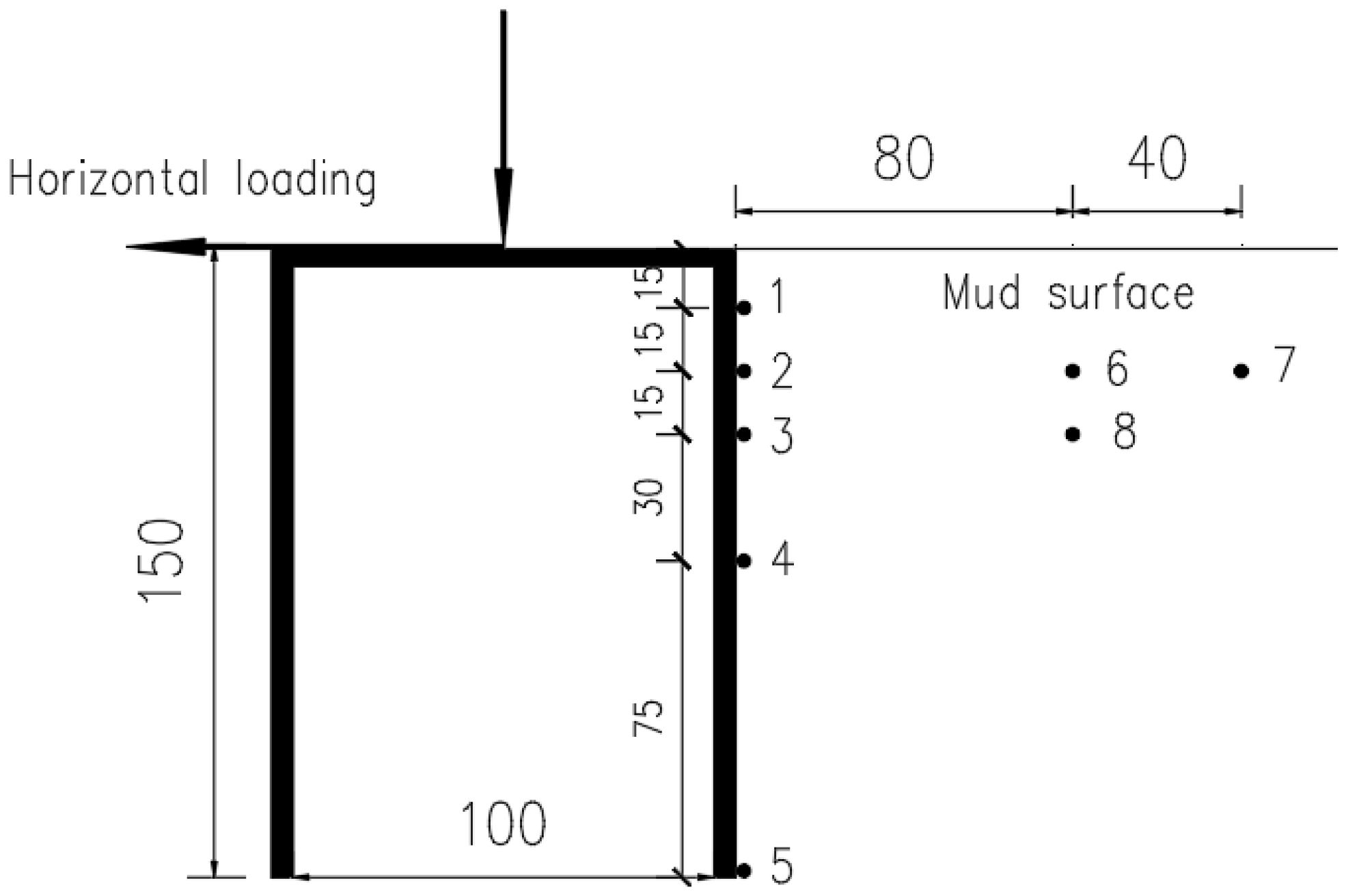
2.1. Bucket Model and Instrumentation

In the model test, the bucket was made of steel. The diameter of the bucket was 100 mm, and the height was 150 mm. Two holes were set on the top of the bucket. One hole was connected to the vacuum device to provide suction pressure during installation, and the other was used to lead out the test element circuits, such as the pore water pressure gauges. The tests were conducted in a model box with a size of 1 m × 1 m × 1.2 m (length × width × height). In order to study the accumulation of pore water pressure at different positions around the bucket, five pore water pressure gauges were installed at different depths, 0.1 L, 0.2 L, 0.3 L, 0.5 L, and 1.0 L, respectively, close to the wall of the bucket. Two gauges were installed at depths of 0.2 L and 0.3 L and a distance of 0.8 D from the bucket wall, and one gauge was also placed at a depth of 0.2 L and 1.2 D from the bucket wall. The arrangement of the pore water pressure gauges is shown in Figure 1. Other equipment to provide the load, to control the test, and to measure the data included the servo motor, the LVDT displacement gauges, the tension gauge, and the dynamic and static data acquisition instruments.

2.2. Test Soil

The test soil in this study was taken from a wind farm in Lianyungang, China. The contents of silt, clay, and sand are 60%, 10%, and 30%, respectively, which is considered as the makeup of a typical silty soil in this region. The soil was screened to ensure the uniformity of the sample, and the soil sample was made into a slurry with a water content of about 60%. A sealable rubber cloth was placed on the box bottom, a gravel drainage layer with thickness of 0.2 m was laid, and a layer of geotextile was installed for drainage. The slurry was then poured into the test box. The vacuum preloading method was used to speed up the consolidation of the test soil, and the vacuum preload was kept at 50 kPa. After 30 days, more slurry was added to the model box to continue preloading, if settlement occurred. Finally, the thickness of the soil layer was maintained at 0.9 m. The soil parameters in the model test are listed in Table 1.

2.3. Test Program

A total of 10 tests were conducted to study the pore pressure response around the suction bucket foundation and its effects on the soil strength and bearing capacity of the bucket foundation. The loading conditions with change in three parameters, horizontal cyclic load amplitude ratio H d / H j , horizontal cyclic frequency f, and vertical load ratio V d / V j , are considered. Vd and Hd are the applied vertical and horizontal loads, and Vj and Hj are the vertical and horizontal ultimate static bearing capacities of the foundation. A summary of the tests is shown in Table 2.

3. Test Results and Analyses

3.1. Development of Pore Water Pressure

Using the measured pore pressure at different depths and different distances, the development and distribution of the pore water pressures under different loading conditions are investigated, and the effects of the horizontal cyclic load amplitude ratio, the horizontal cyclic load frequency, and the vertical load ratio on the accumulation of pore water pressure are analyzed. The distribution of pore water pressure is consistent with that on the external side of the suction anchors in Shen’s [7] numerical model.

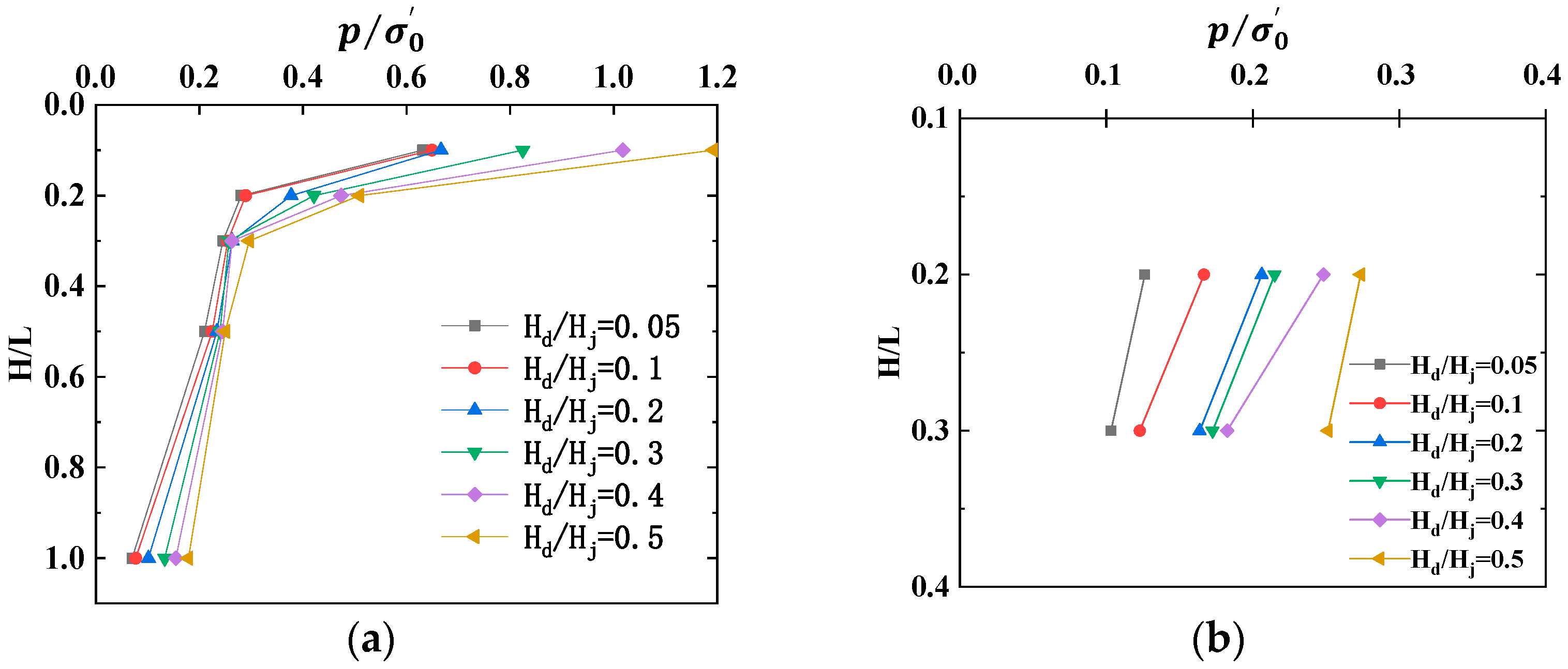
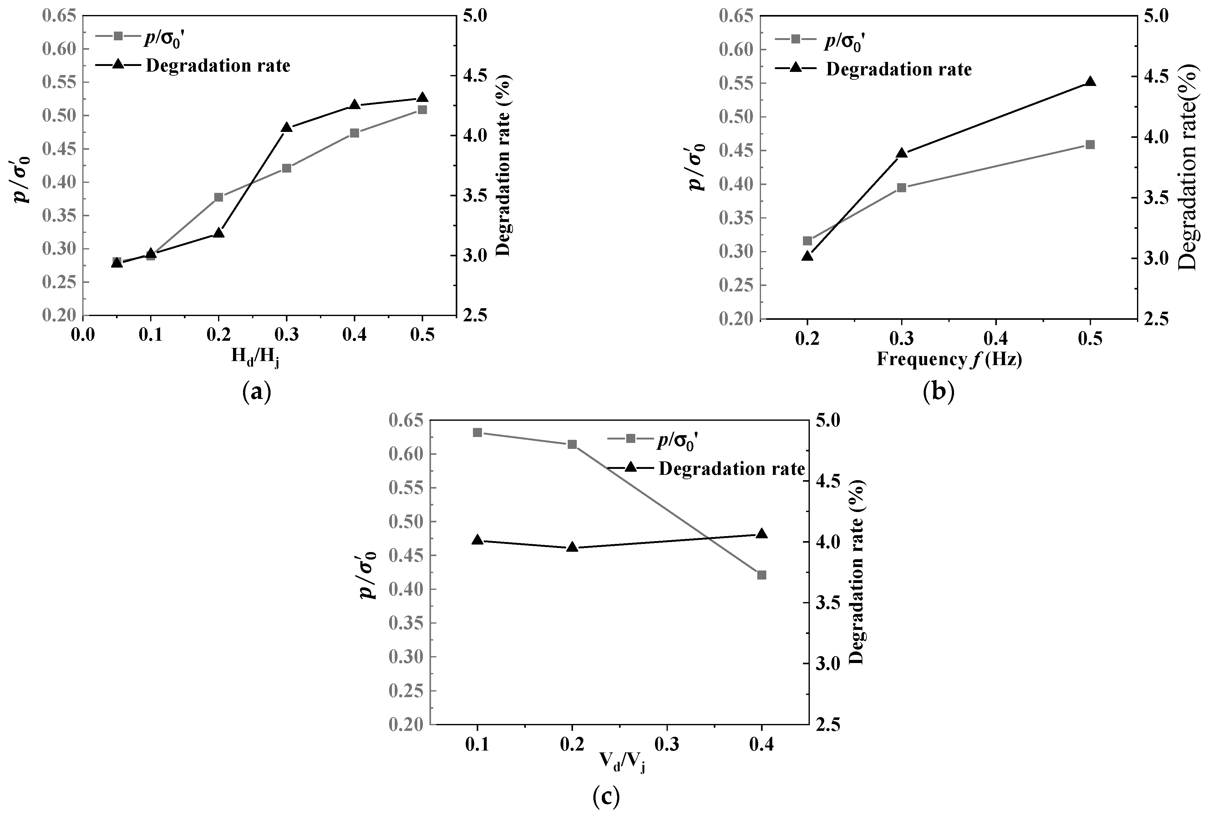
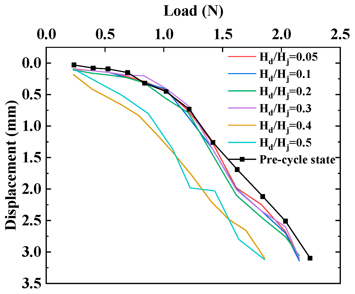
3.1.1. Effect of the horizontal cyclic load amplitude ratio

A series of tests with different V d V j values (0.05, 0.1, 0.2, 0.3, 0.4, 0.5) were conducted to study the effect of horizontal cyclic load amplitude on the accumulation of the pore water pressure. In these tests, the load frequency was set to be 0.2 Hz and the vertical load was set to be 40% of the ultimate static bearing capacity (vertical load ratio V d V j = 0.4 ). The measured pore pressures were normalized with the effective self-weight of the soil, p / σ 0 . Figure 2 shows the normalized pore water pressures at different depths close to the bucket wall, 0.8 D and 1.2 D from the wall, with different horizontal dynamic load amplitudes.
It can be seen from the Figure 2a that at depths between 0.1 L and 0.3 L, the normalized pore water pressures close to the bucket wall change noticeably with different load amplitudes, but below the depth of 0.3 L, the normalized pore water pressures exhibit little change with depth. This means that the accumulation of pore pressure in the shallow soil is more significant under external loading. Taking the data at a depth of 0.2 L as an example, when the load amplitudes are 0.05 and 0.1, the pore pressures are relatively low, while when the load amplitude exceeds 0.1, the pore pressure ratios become larger with the increase in load amplitude.
The pore water pressures at a distance of 0.8 D from the bucket wall and at a depth of 0.2 L and 0.3 L are shown in Figure 2b. The normalized pore pressures at 0.2 L are greater than those at 0.3 L, which is consistent with the distribution of pore water pressure close to the bucket wall, as shown in Figure 2a. Comparing the results at 0.2 L in Figure 2b with those in Figure 2a, the pore pressures measured close to the bucket foundation are about 2 times those at 0.8 D from the bucket wall. However, as the load amplitude increases, the difference at 0.3 L becomes smaller.
Figure 2c shows that the normalized pore water pressures at a distance of 1.2 D from the bucket wall are very small, varying from 0.0088 to 0.0526, which is even smaller than 10% of those measured close to the bucket wall. With an increase in the horizontal cyclic load amplitudes, the trend of normalized pore water pressures increases.

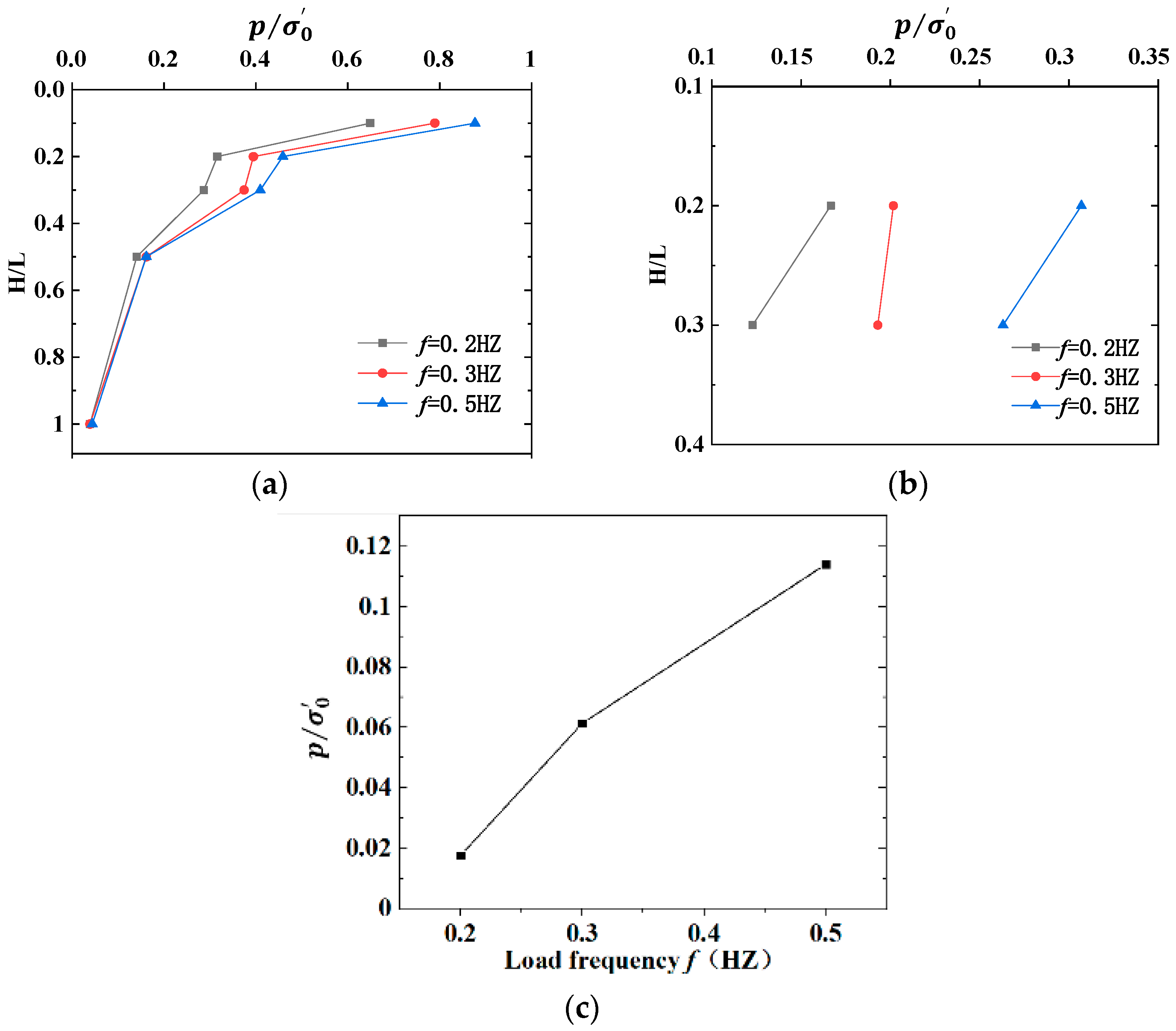
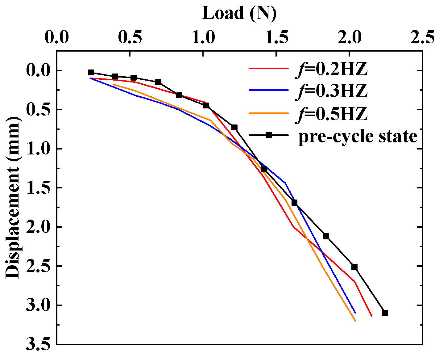
3.1.2. Effect of the Horizontal Cyclic Frequency

With the vertical load ratio of 0.4 and the horizontal cyclic load amplitude ratio of 0.1, different horizontal cyclic frequencies of 0.2 Hz, 0.3 Hz, and 0.5 Hz were applied in Test 3, Test 8, and Test 9 to study the effect of the horizontal cyclic frequency on the dynamic response of the pore water pressure around the bucket foundation. Normalized pore water pressures, with different cyclic load frequencies at different positions, are shown in Figure 3.
As shown in Figure 3a, the distribution of pore pressure around the bucket under different horizontal cyclic frequencies is consistent with that under the vertical cyclic loads [7]. After cyclic loading, the accumulation of pore pressure above 0.5 L close to the bucket wall is obvious, and the normalized pore pressures continue to increase with the increasing load frequency. Figure 3b shows the measured pore pressures at 0.8 D from the bucket wall. Compared with Figure 3a, the measured pore pressures close to the bucket foundation are also about 2 times those at 0.8 D from the bucket foundation.
From Figure 3c, it can be seen that the pore water pressures at a distance of 1.2 D from the bucket wall can still be observed, with the vertical load ratio of 0.4 and the load amplitude ratio of 0.1. The measured pore pressures at 0.8 D from the bucket foundation are about 2.5–3 times those at 1.2 D from the foundation. Moreover, the results of pore water pressure under a higher load frequency (0.5 Hz, p / σ 0 0.116 ) are greater than those under a lower load frequency (0.2 Hz, p / σ 0 0.018 ). The reason may be that the lower the frequency applied, the better the drainage in the test soil, so that the pore water pressure is easy to dissipate.

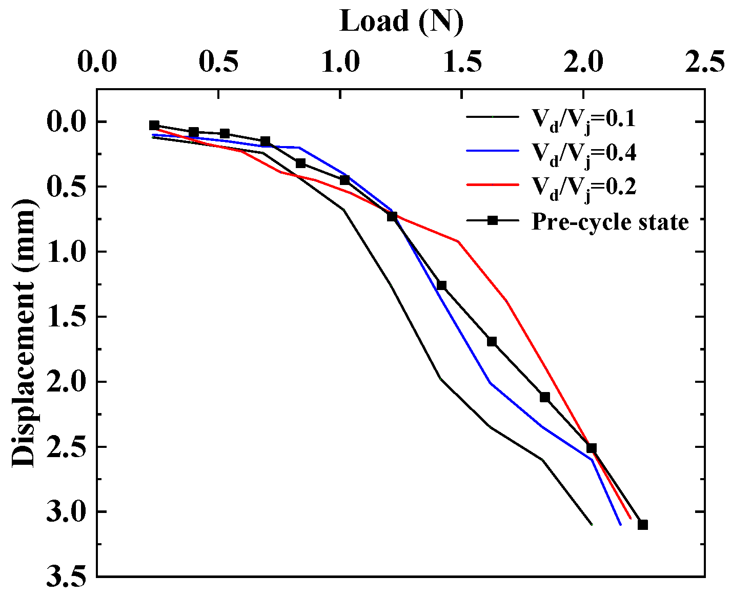
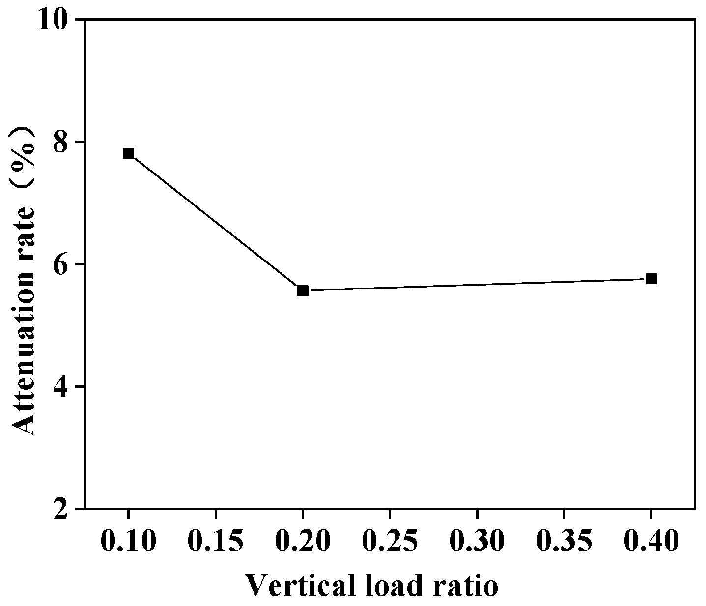
3.1.3. Effect of the Vertical Load Ratio

With the horizontal cyclic load amplitude ratio of 0.3 and a load frequency of 0.2 Hz, different vertical load ratios of 0.1, 0.2, and 0.4 were applied in Test 1, Test 5, and Test 10 to study the effect of the vertical load on the dynamic response of the pore water pressure at different positions around the bucket foundation.
Figure 4a shows that the normalized pore pressures change significantly above a depth of 0.3 L. In addition, the greater the vertical load ratio, the smaller the pore pressure ratio will be, which is similar to the results shown in Figure 4b,c. The reason may be that increasing the vertical load ratio will limit the vibration of the foundation, and the soil will be less disturbed by the horizontal cyclic loading. Therefore, the measured normalized pore pressures with a higher vertical load ratio (0.4) are smaller than those with a lower vertical load ratio in the surface soil, while below 0.5 L, the normalized pore pressures are approximate at the vertical load ratio of 0.1 and 0.2, which are smaller than those at the vertical load ratio of 0.4.
Figure 4c shows the result of measured pore water pressure at 1.2 D from the bucket wall. The smaller vertical load ratio (0.1) causes larger pore-pressure accumulation, and there is no pore water pressure measured at all when the vertical load ratio is 0.4 at a depth of 0.2 L.

3.2. Effects on the Undrained Shear Strength

A micro-penetrometer is a portable geotechnical test instrument that can be used to measure the undrained shear strength of the soil in situ or in laboratory. In this study, the micro-penetrometer was used to measure the undrained shear strength around the bucket foundation before and after the cyclic loading. At a given depth and distance from the bucket wall, three values were measured, and the distance between the three penetration points was less than 3 times the probe diameter. The penetration force and undrained shear strength can be calculated from the readings of the micro-penetrometer.
For sandy soil, it may become denser and the shear modulus may increase under cyclic loads, and no obvious excess pore water pressure will be observed because the pore water pressure can dissipate immediately in sand [11]. Thus, the strength may not degrade. However, for silty seabed soil, due to the content of fine particles, the excess pore water pressure induced by the cyclic load cannot dissipate immediately. The accumulation of excess pore pressure will cause a decrease in effective stress, and the shear strength of the soil will consequently decrease. If the fine particle content is within a certain range, and the excess pore water pressure is equal to the effective stress, the soil will be liquified, and the shear strength will be lost completely. Moreover, compared with the sand under cyclic loading, the fine particles in the silt may be lost during the seepage due to the amplification of excess pore pressure induced by sustained horizontal cyclic loading [24,25]. Liu [26] found that the strength of the silty seabed sediments decreased first, then recovered, and finally enhanced under progressive waves in the wave flume experiment, and the change rate became larger when wave height increased.
The shear strength of the test soil before the cyclic loading was measured, with a value of Suq = 19.739 kPa. The undrained shear strength Suh after each cyclic loading test was then measured. The values of undrained shear strength at a depth of 0.2 L after the tests and degradation rates are listed in Table 3. The degradation of undrained shear strength is consistent with the results of previous research [18,19].
The results show that the undrained shear strength degradation is the most obvious close to the bucket wall, and the farther away from the bucket wall, the lower the undrained shear strength degradation will be. At the same time, the rate of degradation is larger when the load frequency and amplitude are higher. The undrained shear strength degradation rate decreases with the increase in the vertical load ratio, which is consistent with the distribution of the measured pore pressure around the bucket foundation, as shown in Figure 4.
The relationship between normalized pore water pressures p / σ 0 and the undrained shear strength degradation rate at the depth of 0.2 L close to the bucket foundation is shown in Figure 5. It is displayed in Figure 5a,b that the variation in the undrained shear strength degradation rate is consistent with that of the pore water pressure. Under given load conditions, when normalized pore water pressures close to the bucket foundation approach 0.5 ( p / σ 0 0.5 ), the degradation rate of the undrained shear strength is about 4%. With a change in the vertical load ratio ( V d / V j ), Figure 5c shows that the degradation rate of the undrained shear strength exhibits little change, although the normalized pore water pressure decreases from about 0.6 to about 0.4. This means that the vertical load ratio may have little effect on the undrained shear strength of the soil.

3.3. Effects on the Static Horizontal Bearing Capacity of Bucket Foundation

Lateral loads induced by wind and waves in a marine environment are considered to be the main load for offshore wind turbines. The horizontal bearing capacity of the bucket foundation is mainly provided by soil resistance inside and outside of the bucket skirts and the friction between the soil and the bucket wall [27]. Under cyclic loading, the pore water pressures in silty soil cannot dissipate immediately, and the strength of the soil is reduced, as analyzed in Section 3.2. Consequently, the horizontal static bearing capacity of the bucket foundation will be influenced by the cyclic loadings. In this study, the static horizontal bearing capacity of the bucket foundation after 1500 cycles was measured. The loading point of the horizontal static load was located at the top of the bucket to avoid a bending moment. According to the data obtained in this study and the method detailed in the literature, when the lateral displacement reaches 3% of the bucket diameter, the corresponding lateral load is regarded as the ultimate lateral bearing capacity of the bucket foundation [11].
The ultimate horizontal bearing capacity of the suction bucket foundation, before and after the cyclic loadings, and the attenuation rate under different load conditions, are listed in Table 4. It can be seen that after cyclic loading, the static horizontal bearing capacities degrade in a range of 1.57% to 14.90%, under different loading conditions. The larger the cyclic load amplitude and frequency, the higher the degree of horizontal bearing capacity degradation will be, and the smaller the vertical load ratio, the larger the degradation rate will be. These conclusions are consistent with the effects of the load parameter on the normalized pore pressures and the degradation of the undrained shear strength, described in Section 3.1 and Section 3.2. This means that the change of capacity of the foundation can be explained by the change in pore water pressure and soil strength, comprehensively.
The load displacement curves of the bucket foundation, before and after the cyclic loadings, and the bearing capacity attenuation rates under different load conditions are shown in Figure 6, Figure 7, Figure 8, Figure 9, Figure 10 and Figure 11.
Figure 6 shows the load displacement curves of the tests, with different cyclic load amplitudes ratios from 0.05 to 0.5 in tests 2–7, which are compared with the load displacement curve of test before cyclic loading, and the rates of bearing capacity degradation are given in Figure 7. From both the load displacement curves and the bearing capacity degradation rates, it can be seen that when the cyclic load amplitude ratios are smaller than 0.3 in tests 2–5, the curves are approximate, and the degradation ratios show no big differences, but when the cyclic load amplitude ratios are 0.4 and 0.5 in tests 6 and 7, both the load displacement curves and the bearing capacity degradation rates show significant changes. As analyzed previously in Section 3.1, at a depth of 0.2 L, the pore pressure ratios p / σ 0 are between 0.2 to 0.5 when the cyclic load amplitude ratios are smaller than 0.3, as in tests 2–5, but in tests 6 and 7, when the load amplitude ratios are 0.4 and 0.5, the pore pressure ratios p / σ 0 at a depth of 0.2 L are larger than 0.5, and they are larger than 1 at a depth of 0.1 L (see Figure 2). A pore pressure ratio larger than 1 means that the soil may be liquified, and the bearing capacity may be lost at this given location. In summary, a larger load amplitude ratio causes larger pore water pressure, and the displacement and consequently, the bearing capacity attenuation rate under certain load conditions will be higher.
The load displacement curves and the bearing capacity degradation ratios of the tests with different cyclic load frequencies of 0.2, 0.3, and 0.5 Hz in tests of 3, 8, and 10 are shown in Figure 8 and Figure 9, respectively. This shows that the load frequency has little influence on the load displacement curve. The attenuation rates of the bearing capacity are 2.05%, 6.48%, and 8.57%, respectively, with cyclic frequencies of 0.2, 0.3, and 0.5 Hz. This means that the degradation increases with the increase in load frequency. Analyses of the pore pressure at a depth of 0.2 L show that there are some accumulations of pore pressure, but that the pore pressure ratios are all smaller than 0.5 (see Figure 3).
Figure 10 and Figure 11 show the load displacement curves and the bearing capacity attenuation rates of the tests, with different vertical load ratios of 0.1, 0.4 and 0.2 in Test 1, Test 5, and Test 10, respectively. It can be seen in Figure 10 that the displacement is larger under the same load at V d / V j = 0.1 compared with the pre-cycle state, and the bearing capacity attenuation rate is also relatively larger, as shown in Figure 11. Considering the development of pore pressure, the increase in the vertical load may restrict the accumulation of pore pressure (see Figure 4), but Figure 5c shows that the degradation rate of the undrained shear strength of the soil shows no big difference (about 4% close to the bucket at the depth of 0.2 L) under different vertical load ratios (see Figure 5c), so the bearing capacity attenuation rate is approximate (about 6%) when the vertical load ratios are 0.2 and 0.4.

4. Discussion

The main goal of this paper is to investigate the bearing capacity of the bucket foundation in silty soil under cyclic loading conditions. It is well known that the reduction of the bearing capacity of the bucket foundation may be caused by the strength degradation of the surrounding soils, which may be a consequence of the development of the pore water pressure during cyclic loading. The development of the pore water pressure due to cyclic loading, the strength degradation of the soil due to the pore water pressure accumulation, and the reduction of the bearing capacity of the bucket foundation have all been analyzed extensively, but separately, in the literature, but these three topics have seldom been studied comprehensively and causally. This is the main concept and content of this paper.
In this paper, from the experimental model test, the accumulation of pore pressure at depths between 0.1 L and 0.3 L was found to noticeably change, and the values close to the bucket foundation were shown to be about 2 times those at 0.8 D from the bucket wall. The reduction in the undrained shear strength of the soil is consistent with the distribution of the pore water pressure under different cyclic conditions. Consequently, the ultimate static horizontal bearing capacity was attenuated, with rates in a range of 1.57% to 14.90%, under different loading conditions. This can be explained by the corresponding distribution of the pore pressure and the degradation of the soil strength.
It should be noted that the results of this paper are based on specific soils from a wind farm in China. The contents of the silt, clay, and sand are given, but the particle contents are known to have a significant effect on the soil behaviors, including the development of the pore water pressure and the soil strength. Thus, the conclusions of this paper are supposed to be qualitatively reasonable, but the results may change quantitatively with different soils. Additional study of the effects of particle contents on the development of the pore water pressure and consequently, on the soil strength degradation, may be meaningful. Moreover, the analysis of the bearing capacity is provided for a bucket foundation with the given geometry. The foundation may have different sizes and length-diameter ratios, so the results regarding the bearing capacity are given mainly for a qualitative analysis.

Author Contributions

Conceptualization, X.-L.Z. and W.-N.D.; methodology, X.W. and P.-C.D.; data curation, X.W.; writing—review and editing, S.-H.S.; supervision, X.-L.Z. All authors have read and agreed to the published version of the manuscript.

Funding

This research received no external funding.

Institutional Review Board Statement

Not applicable.

Informed Consent Statement

Not applicable.

Data Availability Statement

Not applicable.

Conflicts of Interest

The authors declare no conflict of interest.

References

  1. Clukey, E.C.; Kulhawy, F.H.; Liu, P.L.F.; Tate, G.B. The impact of wave loads and pore-water pressure generation on initiation of sediment transport. Geo-Mar. Lett. 1985, 5, 177–183. [Google Scholar] [CrossRef]
  2. Wang, H.; Liu, H.-J. Evaluation of storm wave-induced silty seabed instability and geo-hazards: A case study in the Yellow River delta. Appl. Ocean. Res 2016, 58, 135–145. [Google Scholar] [CrossRef]
  3. Xu, G.; Sun, Y.; Wang, X.; Hu, G.; Song, Y. Wave-induced shallow slides and their features on the subaqueous Yellow River delta. Can. Geotech. J. 2009, 46, 1406–1417. [Google Scholar] [CrossRef]
  4. Zhao, H.; Jeng, D.-S.; Zhang, H.; Zhang, J.; Zhang, H. 2-D integrated numerical modeling for the potential of solitary wave-induced residual liquefaction over a sloping porous seabed. J. Ocean Eng. Mar. Energy 2015, 2, 1–18. [Google Scholar] [CrossRef]
  5. Jeng, D.S.; Zhao, H.Y. Two-Dimensional Model for Accumulation of Pore Pressure in Marine Sediments. J. Waterw. Port Coast. Ocean Eng. 2015, 141, 04014042. [Google Scholar] [CrossRef] [Green Version]
  6. Liao, C.; Chen, J.; Zhang, Y. Accumulation of pore water pressure in a homogeneous sandy seabed around a rocking mono-pile subjected to wave loads. Ocean Eng. 2019, 173, 810–822. [Google Scholar] [CrossRef]
  7. Shen, K.; Wang, L.; Guo, Z.; Jeng, D.S. Numerical investigations on pore-pressure response of suction anchors under cyclic tensile loadings. Eng. Geol. 2017, 227, 108–120. [Google Scholar] [CrossRef]
  8. Zhang, J.-F.; Zhang, X.-N.; Yu, C. Wave-induced seabed liquefaction around composite bucket foundations of offshore wind turbines during the sinking process. J. Renew. Sustain. Energy 2016, 8, 023307. [Google Scholar] [CrossRef]
  9. Tasan, H.E.; Yilmaz, S.A. Effects of installation on the cyclic axial behaviour of suction buckets in sandy soils. Appl. Ocean Res. 2019, 91, 101905. [Google Scholar] [CrossRef]
  10. Le, V.H.; Remspecher, F.; Rackwitz, F. Development of numerical models for the long-term behaviour of monopile foundations under cyclic loading considering the installation effects. Soil. Dyn. Earthq. Eng. 2021, 150, 106927. [Google Scholar] [CrossRef]
  11. Wang, X.; Yang, X.; Zeng, X. Centrifuge modeling of lateral bearing behavior of offshore wind turbine with suction bucket foundation in sand. Ocean Eng. 2017, 139, 140–151. [Google Scholar] [CrossRef]
  12. Ma, P.; Liu, R.; Lian, J.; Zhu, B. An investigation into the lateral loading response of shallow bucket foundations for offshore wind turbines through centrifuge modeling in sand. App. Ocean Res. 2019, 87, 192–203. [Google Scholar] [CrossRef]
  13. Wang, Y.; Lu, X.; Wang, S.; Shi, Z. The response of bucket foundation under horizontal dynamic loading. Ocean Eng. 2006, 33, 964–973. [Google Scholar] [CrossRef] [Green Version]
  14. Li, D.; Zhang, Y.; Feng, L.; Gao, Y. Capacity of modified suction caissons in marine sand under static horizontal loading. Ocean Eng. 2015, 102, 1–16. [Google Scholar] [CrossRef]
  15. Jia, N.; Zhang, P.; Liu, Y.; Ding, H. Bearing capacity of composite bucket foundations for offshore wind turbines in silty sand. Ocean Eng. 2018, 151, 1–11. [Google Scholar] [CrossRef]
  16. Liu, M.; Yang, M.; Wang, H. Bearing behavior of wide-shallow bucket foundation for offshore wind turbines in drained silty sand. Ocean Eng. 2014, 82, 169–179. [Google Scholar] [CrossRef]
  17. Lazcano, D.R.P.; Aires, R.G.; Nieto, H.P. Bearing capacity of shallow foundation under cyclic load on cohesive soil. Comput. Geotech. 2020, 123, 103556. [Google Scholar] [CrossRef]
  18. Hodder, M.S.; White, D.J.; Cassidy, M.J. Analysis of soil strength degradation during episodes of cyclic loading, illustrated by the T-Bar penetration test. Int. J. Geomech. 2010, 10, 117–123. [Google Scholar] [CrossRef]
  19. Ajmera, B.; Brandon, T.; Tiwari, B. Characterization of the reduction in undrained shear strength in fine-grained soils due to cyclic loading. J. Geotech. Geoenviron. 2019, 145, 04019017. [Google Scholar] [CrossRef]
  20. Moses, G.G.; Rao, S.N. Degradation in cemented marine clay subjected to cyclic compressive loading. Mar. Georesour. Geotechnol. 2003, 21, 37–62. [Google Scholar] [CrossRef]
  21. Chu, M.C.; Ge, L. Stiffness degradation of coarse and fine sand mixtures due to cyclic loading. Eng. Geol. 2021, 288, 106155. [Google Scholar] [CrossRef]
  22. Hanna, A.M.; Javed, K. Experimental investigation of foundations on sensitive clay subjected to cyclic loading. J. Geotech. Geoenviron. 2014, 140, 04014065. [Google Scholar] [CrossRef]
  23. Mao, D.; Zhong, C.; Zhang, L.; Chu, G. Dynamic response of offshore jacket platform including foundation degradation under cyclic loadings. Ocean Eng. 2015, 100, 35–45. [Google Scholar] [CrossRef]
  24. Tzang, S.-Y.; Ou, S.-H. Laboratory flume studies on monochromatic wave-fine sandy bed interactions. Coast. Eng. 2006, 53, 965–982. [Google Scholar] [CrossRef]
  25. Tzang, S.-Y.; Ou, S.-H.; Hsu, T.-W. Laboratory flume studies on monochromatic wave-fine sandy bed interactions Part 2. Sediment suspensions. Coast. Eng. 2009, 56, 230–243. [Google Scholar] [CrossRef]
  26. Liu, X.-L.; Jia, Y.-G.; Zheng, J.-W.; Hou, W.; Zhang, L.; Zhang, L.P.; Shan, H.X. Experimental evidence of wave-induced inhomogeneity in the strength of silty seabed sediments: Yellow River Delta, China. Ocean Eng. 2013, 59, 120–128. [Google Scholar] [CrossRef]
  27. Wang, X.; Zeng, X.; Yu, H.; Wang, H. Centrifuge Modeling of Offshore Wind Turbine with Bucket Foundation under Earthquake Loading. In Proceedings of the IFCEE 2015, San Antonio, TX, USA, 17–21 March 2015; pp. 1741–1750. [Google Scholar]
Figure 1. Arrangement of pore pressure gauges (mm).
Jmse 10 02020 g001
Figure 2. Normalized pore pressures with different horizontal cyclic load amplitudes: (a) close to the wall; (b) 0.8 D from the bucket; (c) 1.2 D from the bucket(0.2 L).
Jmse 10 02020 g002aJmse 10 02020 g002b
Figure 3. Normalized pore water pressures with different cyclic load frequencies: (a) close to the wall; (b) 0.8 D from the wall; (c) 1.2 D from the wall (at 0.2 L).
Jmse 10 02020 g003
Figure 4. Normalized pore pressures with different vertical load ratios: (a) close to the bucket; (b) 0.8 D from the bucket; (c) 1.2 D from the wall (at 0.2 L).
Jmse 10 02020 g004
Figure 5. Relationship between p / σ 0 and undrained shear strength degradation rate: (a) horizontal cyclic load amplitude ratio; (b) horizonal cyclic load frequency; (c) vertical load ratio.
Jmse 10 02020 g005
Figure 6. Load displacement curves with different cyclic load amplitudes ratios.
Jmse 10 02020 g006
Figure 7. Bearing capacity attenuation rates with different cyclic load amplitude ratios.
Jmse 10 02020 g007
Figure 8. Load displacement curves with different cyclic frequencies.
Jmse 10 02020 g008
Figure 9. Degradation ratios of bearing capacity with different cyclic frequencies.
Jmse 10 02020 g009
Figure 10. Load displacement curves with different vertical load ratios.
Jmse 10 02020 g010
Figure 11. Degradation ratios of bearing capacity with different vertical load ratios.
Jmse 10 02020 g011
Table 1. Soil parameters.
Particle Content (%)
(Silt–Clay–Sand)
Density
(kN·m−3)
Consolidation Coefficient (m2/s)Permeability
(m/s)
Porosity Ratio
60–10–3019.01.26 × 10−68.6 × 10−60.814
Table 2. Summary of all the tests.
Test NO.Vertical Load Ratio,
V d / V j
Cyclic Frequency,
f (Hz)
Cyclic Load Amplitude Ratio,
H d / H j
Test 10.10.20.3
Test 20.40.20.05
Test 30.1
Test 40.2
Test 50.3
Test 60.4
Test 70.5
Test 80.30.1
Test 90.50.1
Test 100.20.20.3
Table 3. Degradation rate of undrained shear strength.
Distance from Bucket WallSuhDegradation Rate (%)
Test 1018.9474.01
0.8 D19.0143.67
1.2 D19.1732.87
Test 2019.1622.93
0.8 D19.2542.45
1.2 D19.4171.63
Test 3019.1463.01
0.8 D19.2522.47
1.2 D19.4701.36
Test 4019.1103.18
0.8 D19.2212.62
1.2 D194261.58
Test 5018.9374.06
0.8 D19.0023.73
1.2 D19.1962.75
Test 6018.9004.25
0.8 D19.0113.69
1.2 D19.1403.03
Test 7018.8894.31
0.8 D19.0363.56
1.2 D19.0973.25
Test 8018.9773.86
0.8 D19.0023.73
1.2 D19.1782.84
Test 9018.8614.45
0.8 D19.0263.61
1.2 D19.1622.92
Test 10018.9603.95
0.8 D19.0263.61
1.2 D19.1333.07
Table 4. Degradation rate of undrained shear strength.
Test NO.Vertical Load Ratio,
V d / V j
Cyclic Frequency,
f (Hz)
Load Amplitude Ratio,
H d / H j
Bearing Capacity (N)Attenuation Rate (%)
Before loading---2100
Test 10.10.20.3193.67.81
Test 20.40.20.05206.71.57
Test 30.1205.72.05
Test 40.2203.92.91
Test 50.3197.95.76
Test 60.4181.013.80
Test 70.5178.714.90
Test 80.30.1196.46.48
Test 90.50.1192.08.57
Test 100.20.20.3198.35.57
Publisher’s Note: MDPI stays neutral with regard to jurisdictional claims in published maps and institutional affiliations.

