Abstract
CAD software is a daily tool in ship design offices and shipyards, and every software uses NURBS or B-splines curves and surfaces as common foundations. The CAD tools of today are not static software products and most of them now include parametric design modules, which enable users to change the shape of an object based on its key geometric feature parameters with the use of sliders or equivalent controls. Although B-spline techniques are commonly applied to the representation of the ship hull curves and surfaces, the parametric deformation of the hull surfaces based on geometric parameters is less used. This paper presents a methodology to define the parametric definition of a ship hull with the use of a standard and non-specialized CAD software that is of common use in the ship design offices and universities: Rhinoceros. The presented parametric design methodology will use specific ship hull parameters or feature parameters with a clear geometric meaning, such as displacement, waterplane area, LCB, and LCF, together with the properties of the B-spline curves and the power of Grasshopper, the parametric design tool inside Rhinoceros, to create parametric ship hulls.
1. Introduction
The ship hull design is one of the first steps of the ship’s design process after the selection of the ship’s main dimensions and hull parameters. The design of efficient ship hulls is today an important research topic, due to the development of computer capabilities together with the CFD tools and optimization algorithms [1,2]. The design is normally developed using the Design Spiral [3] and repeating the different steps improves the accuracy and diminishes the design uncertainty during the different stages: concept, basic, and detailed design.
In the design offices and shipyards, CAD tools used to represent and model in 3D the ship hull play an important role, since the 3D representation is the first stage for all the project design and calculations: hydrodynamics, stability, tank definition, etc. The ship hull representation needs to be accurate to produce a faired set of surfaces, enabling the generation of geometric variations of the hull in an easier way, e.g., with a reduced number of parameters or inputs and with a clear meaning between the numerical parameter and induced surface modification. A key design feature to accelerate the design process is having a flexible/parametric method to design an initial hull that also enables the modification of the shape in the next phases.
This paper presents a Parametric Approach (PA) to represent the hull shape within a CAD model using only CAD software, since today the evolution of these software products tends towards the parametric design, with a strong integration of computational methods into the CAD tool. This key innovation enables efficient design solutions and reduces the overall time of the design process.
NURBS is a common tool in CAD and in ship design. Just refer to the references from Harries [4,5], following the previous work from Nowacki [6]. These authors introduce the parametric representation of ship hulls and the use of basic curves of the hull in the parametric definition. These bases have been widely used in Naval Architecture in Hydrodynamic hull shape optimization by some authors [7,8].
The parametric design of ship hulls began in the 1970s with Kuiper [9], who used mathematics to represent a ship hull surface, improving the use of traditional offsets, a discrete set of data points presented in tabular form. The works of Nowaki and Harries have been mentioned previously and set the base of later research, such as the work of Kim [10], which applied mathematical expressions to the section curves of a bulbous bow, in a similar way to the reference [11]. The key in parametric design is the implementation of constraints, mainly area and centroid, into some ship curves. Related to that are the works from Birk et al. [12] and Zhang [13], both using B-spline curves and surfaces. Other interesting papers are the ones from Nam [14,15], which also used a constrained design of NURBS curves to recreate ship hull sections.
The importance of fairing has been mentioned in the introduction, and Sarioz [16] used optimization techniques based on parameters applied to a ship hull. As mentioned, PA is limited in the range of ship hull forms that can be reproduced; different hulls such as catamaran hulls may require specific methods, as can be found in [17]. Two recent references about the parametric design of ships are [18,19], showing that parametric ship design is an active subject for the Academy. Rhinoceros and Grasshopper have been used in parametric design in [20] for the parametric definition of SWATH hulls that can be defined with the use of equations.
Another option for ship hull design is the use of non-parametric procedures, i.e., [21,22,23], that are based on a set of mathematical transformations of an existing parent hull or parent shapes. This option is out of the scope of this paper. The main characteristic of a PA for a ship hull is that its definition starts with the creation of the surface itself, and in the case of non-parametric procedures, the surface is already defined and a set of generic transformations (scaling, morphing, Lackenby, etc.) are imposed on it.
The use of a PA improves the interactive design process that involves the design of a ship, which covers from hydrostatics and hydrodynamics to structural analysis and propulsion. Trends in ship design [24,25] push the idea of eliminating the need for several iterations and design evaluations. A PA allows shape variations that are common to the naval architect, e.g., the inclusion of the waterline in the set of basic curves, and its definition with common parameters for a naval architect such as the waterplane area. This means that this area, a pure geometric value, can be considered a free variable in the following optimization process.
This is of great value to the naval architect, who is used to working with such geometric parameters whose effect on some ship characteristics is known and can now be included in the digital design of a ship hull shape inside the CAD software environment. Moreover, this helps to clarify the ideas behind the design of a ship hull and makes the effect of a single parameter change easier to be identified in the 3D hull surface since it is previously displayed in the 2D basic curves.
However, there are some drawbacks of the PA in the design of a new hull, which is the selection of the parameters and basic curves. Since the output of the PA is the hull surface itself, the designer needs to know in advance the distribution of the geometric parameters of a hull surface that has not been already defined. In addition, another disadvantage is the domain of the possible shape variations that are constrained at the beginning of the PA process.
On the contrary, a non-parametric procedure is easier to set up since it depends on several transformations to an initial and known hull shape. However, these transformations need to be carefully controlled in order to get faired hulls which is very important in naval architecture. This relies on the visual considerations of expert designers rather than on mathematical formulations related to derivatives. Even if these mathematical methods are used, a final check from an expert is conducted. This is a drawback of non-parametric procedures: the transformations of the hull are global and not local shape changes that may produce an unfaired hull surface.
In order to cover different types of ship hulls, PA may contain a large number of scalar parameters. In the presented methodology, this is avoided by defining some of the basic curves of the hull drawing directly in the CAD software. This simplifies the definition of the PA and produces more flexibility in the design process. If, for example, the longitudinal position of a point in the centerline profile has not been connected to any parameter, there is no way to move it from its reference location, and this is solved by obtaining the point directly from the centerline. This curve has been sketched by the designer in the CAD software and can be easily modified with the use of the curve’s control points.
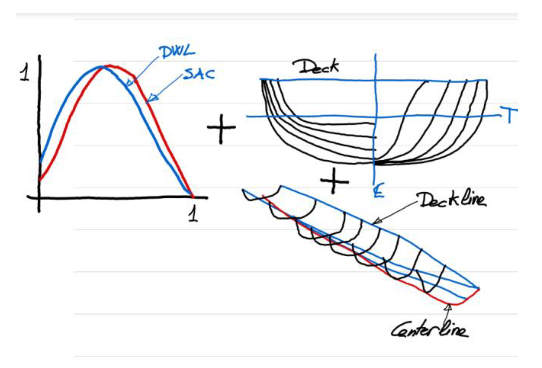
The presented methodology uses as basic curves the profile curve at the ship’s keelline, also called Center Line (Zk(x)), and the Deck Line (Yd(x), Zd(x)) that the designer can draw manually in the CAD software as B-spline curves.
The methodology will compute another two basic curves, see Figure 1, based on geometric parameters: the Design Waterline (DWL) at the design draft, and the Sectional Area Curve (SAC). In order to get these curves, computational tools available in the CAD software are used, simplifying the problem of obtaining a curve that encloses a given area and with a provided centroid. This requires solving a nonlinear set of equations in the system.
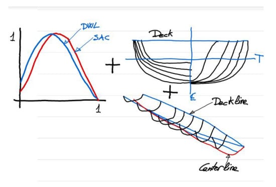
Figure 1.
Sketch for methodology.
Novelties and contributions of this paper are:
- (1)
- The use of a hybrid methodology that combines the use of a PA to define the DWL and the SAC, together with a non-parametric definition of the Center line and Deck line, hence reducing the number of parameters and easing rapid modification of the hull.
- (2)
- With these four curves, a wire model with the hull stations can be automatically defined. As detailed in Section 3, the stations will use the starting angle at the Keel, also called the Deadrise angle, k(x), and the flare angle at the Deck, αd. The distribution of this angle in degrees is imposed by the designer and enables local modifications of the hull. A final lofting, also called skinning of the stations, produces the final surface.
- (3)
- All the calculations and representation of the PA for the ship hull are produced with the use of standard and non-specialized CAD software, which is commonly used in ship design offices and universities: Rhinoceros and its parametric module Grasshopper.
The organization of this paper is as follows:
Section 1 has described the advantages of a PA and presented background and references about parametric ship hull design.
Section 2 will show how a constrained design of the SAC and DWL can be conducted inside the CAD software with the use of optimization techniques that can set an enclosed area and a centroid to a curve, without using nonlinear equations.
Section 3 describes how to create hull stations enclosing a submerged area from the previously defined SAC, and with a half beam from the DWL. When these sets of curves are defined, a wire model of the ship hull with the displacement, LCB, AWP, and LCF is achieved. In this section, the way to create the above-water part of the ship is also explained. This part connects the waterline with the deck.
Section 4 and Section 5 present application examples that show the different hull forms that can be obtained with the presented methodology.
Section 6 contains relevant conclusions about this work and also mentions the limitations of the present PA that cannot be considered a universal method for ship design.
2. Constrained Design of the SAC and DWL
This section presents the way to define a B-spline curve that encloses a given area with the abscissa axis X, and with a given longitudinal centroid of this area. The application is clear for the SAC, where the area of the curve is the ship’s displacement, and its centroid is the LCB. In the case of the DWL, the area and centroid will be the waterplane area AWP and LCF.
There are some references to produce a constrained design of a curve, [12,26]. They include the solution of nonlinear sets of equations to compute the position of the control points of the constrained B-spline. In this paper, the position is obtained using the computational capabilities of the CAD software that include optimization methods to compute the control points of the curves. The first step in any parametric design methodology is the selection of the parameters and this has to be accomplished in a smart way to avoid a large number of elements. The properties of the B-spline curves play an important role in this definition: the curve interpolates the control points at its ends, and the first and last segments of the control polygon are tangent to the curve, which is very useful in defining the entrance angle.
Another important property affects the B-spline curves of the second degree: the B-spline is tangent at the midpoints of its control polygon, for all the legs except the first and the last ones that interpolate their ends.
The curve will be presented uniformly, which means that it is contained in a square of 1 by 1 units by dividing its abscissa and ordinate by the maximum values of the curve. In the case of the SAC, this is by the maximum submerged area Ax and the LWL, and in the case of the DWL, by the maximum breadth Bx and the LWL.
Using the uniform expression for the SAC has another interesting application: the area enclosed by the uniform curve of Equation (1) is the ship’s prismatic coefficient Cp, which is clear for a naval architect and indicates if the volume is distributed near the ends of the ship, high Cp, or near the center with fine ends, low Cp.
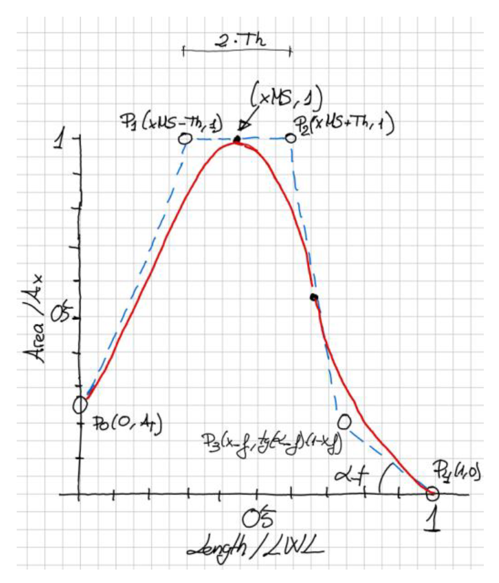
A sketch is also recommended when working with CAD algorithms, since the variables can be presented clearly and the geometric properties are easier to understand graphically. This sketch is presented in Figure 2 and shows a B-spline curve of the second degree with five control points in red, and its control polygon in blue.
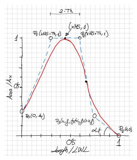
Figure 2.
Sketch for the constrained design of the SAC.
The first control point is P0 and contains the value of the submerged transom area AT (it is divided by the Ax but this is not written for the sake of clarity of the sketch).
The second and third control points P1 and P2 will use the mentioned property of the second-degree B-spline that is tangent in the midpoints of its control polygon. This way a parameter that the designer can impose is the position of the maximum area xMS (again divided by LWL) that has a clear meaning for a naval architect. A numerical parameter Th (from Thickness) is used and will be used to easily define the position of P1 and P2 as a function of xMS as displayed in the sketch.
This Th value can be used to increase or reduce the area of the curve in its middle part and although it has a clear geometric meaning, it is not used in naval architecture. Nevertheless, Th is computed automatically by the optimization algorithm when imposing the area and centroid to the curve.
The fourth control point P3 is a function of a parameter called x_f (f from fore) and of an angle α_f that is related to the curve’s entrance angle at its fore part. While the geometric meaning of this angle is clear, as a lower value produces sharper sections, the parameter x_f is necessary for the definition of P3 and, in a similar way to Th, it will be computed by the optimization algorithm.
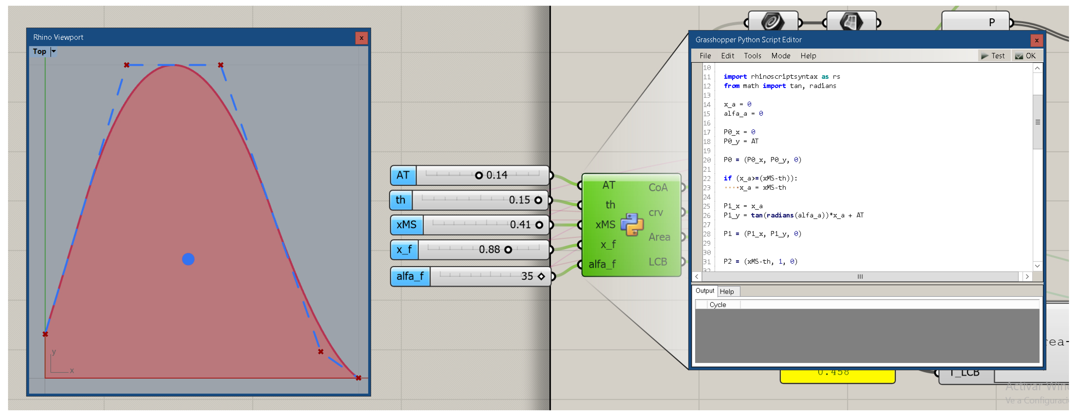
The fifth and last control point P4 is easy to define. The CAD version of the described SAC appears in Figure 3. The left part of this figure shows the SAC in red with five control points, with its control polygon in blue. The red B-spline is tangent in the midpoint of the second and third legs of the blue control polygon. The middle of the figure shows the five parameters AT, Th, xMS, x_f, and α_f, which define the position of the control points. These parameters are the inputs for a Python component that contains the script that defines the control points as described, and hence the B-spline curve of the second degree, which is one of the outputs together with its enclosed area and centroid, which is the large blue dot inside the curve.
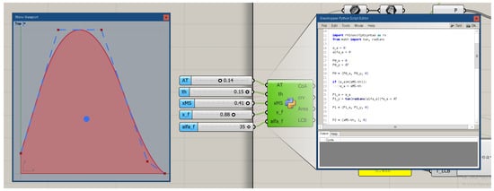
Figure 3.
The SAC defined in Grasshopper.
The SAC is defined inside Grasshopper, the parametric scripting environment of Rhinoceros CAD Software, using Python as can be partly seen in the right part of the Figure. Notice how the parameters are introduced with sliders, whose value and limits can be modified easily, producing a range of different curves as depicted in Figure 4. The designer can easily interact using the sliders and automatically receive the area (Displacement) and centroid of the curve (LCB).

Figure 4.
Different curves altering the parameters.
This fluid behavior that today is natural for a CAD user, previously demanded of the parametric environment the execution of external software to compute the curve’s control points, then the curve’s area and centroid, before going back to the CAD environment to represent the B-spline to check that everything was correct. This required a certain time and patience.
However, the power of computational methods is applied when optimization techniques are used. In other words, this technique obtains the value of the parameters (sliders) to get a given area and centroid. There are several free optimization modules that work for Grasshopper and in this paper, the optimization module used is Silvereye [27], which employs a class of optimization algorithms called particle swarm optimization (PSO).
Due to the fast increase in computing power today, optimization algorithms such as PSO are very popular for working out engineering design tasks. These numerical schemes are self-organized, self-adapted, and very robust and efficient, and belong to the field of swarm and collective intelligence [28], also presenting a “quick” convergence speed.
With a PSO algorithm, designers can explore hundreds of potential solutions with the use of computational optimization, in order to maximize or minimize a target value and consider certain constraints.
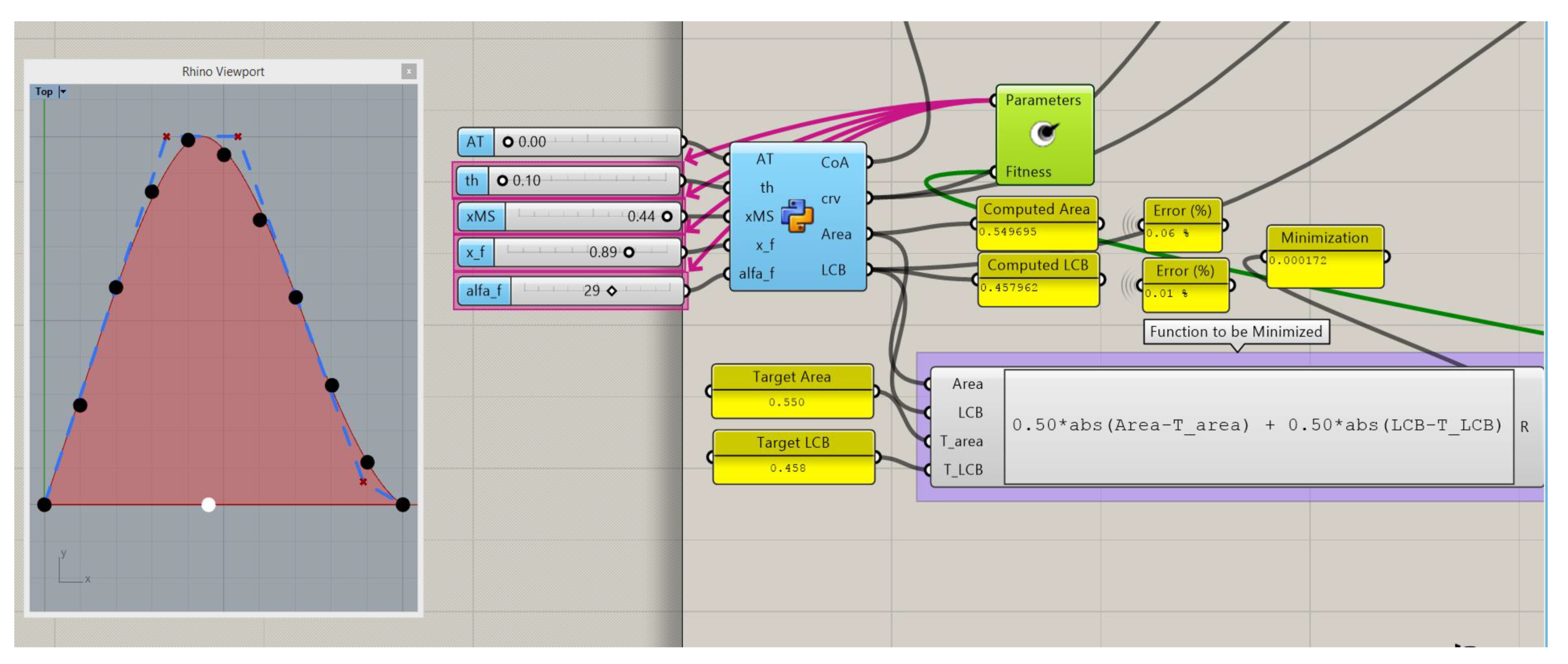
The optimization components can be seen in Figure 5, where Silvereye appears in green in the middle. Pink arrows indicate the parameters that the optimization uses. In this example, the ship does not submerge the transom, so its area is zero. The rest of the parameters are modified inside a range that is constrained by the user and the optimization minimizes a given function or value.
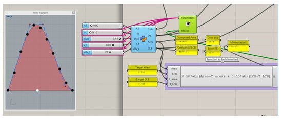
Figure 5.
Optimization example to get a target Area (0.550) and LCB (0.458).
Optimization algorithms maximize or minimize the output of one single function. In this particular case where the minimization of the errors of area and centroid are needed, the proposed methodology uses Equation (2) for minimization:
where T_area and T_LCB are the target values that are searched. The weights of 0.5 can be changed by different combinations as long as their total is 1. If the user wants to reduce the error in the area (displacement), increase the first weight and reduce the second one below 0.5.
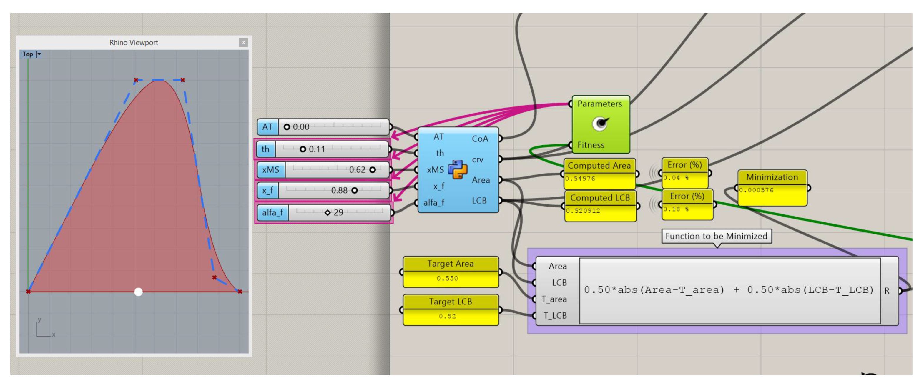
The optimization algorithms normally maximize or minimize a single value in order to be efficient and relatively fast (less than one minute for this example in an Intel Core i7 2600 CPU, 3.4 GHz, 6 GB RAM). For the optimization of area and LCB, the function that appears in the right part of the figure is used. It depends on the difference of target values minus the computed values of the B-spline curve.
The presented example Is based on a real SAC of a sailing ship, and the black dot In the left part of the figure was obtained for the design condition of this ship. There is a good agreement between the computed curve and the target values, the error is <0.1%, and the shape of the computed SAC in red at the left part of the figure is realistic when compared with the dots obtained from a real ship.
Another example appears in Figure 6 which is a modification of the previous one that maintains the area but displaces forward the curve’s centroid. In this case, the optimization slightly alters all the parameters except xMS, which needs to be altered forward to obtain the new position of the centroid. In this case, the interval of this parameter (slider) has to be increased by the user.
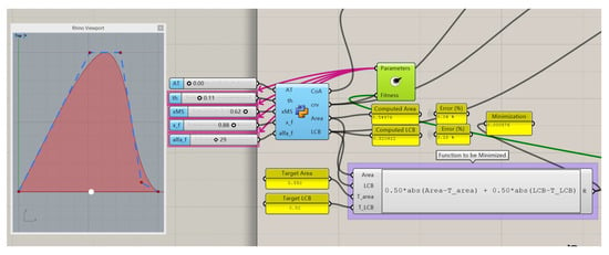
Figure 6.
Optimization example to get a target Area (0.550) and LCB (0.520).
For this particular example, an LCB greater than 0.5 is not common in ship design, and hence the alteration of the intervals is an indicator that something can be wrong. Mathematics can stand different values but it is the user that needs to judge if the results are good enough for a ship design.
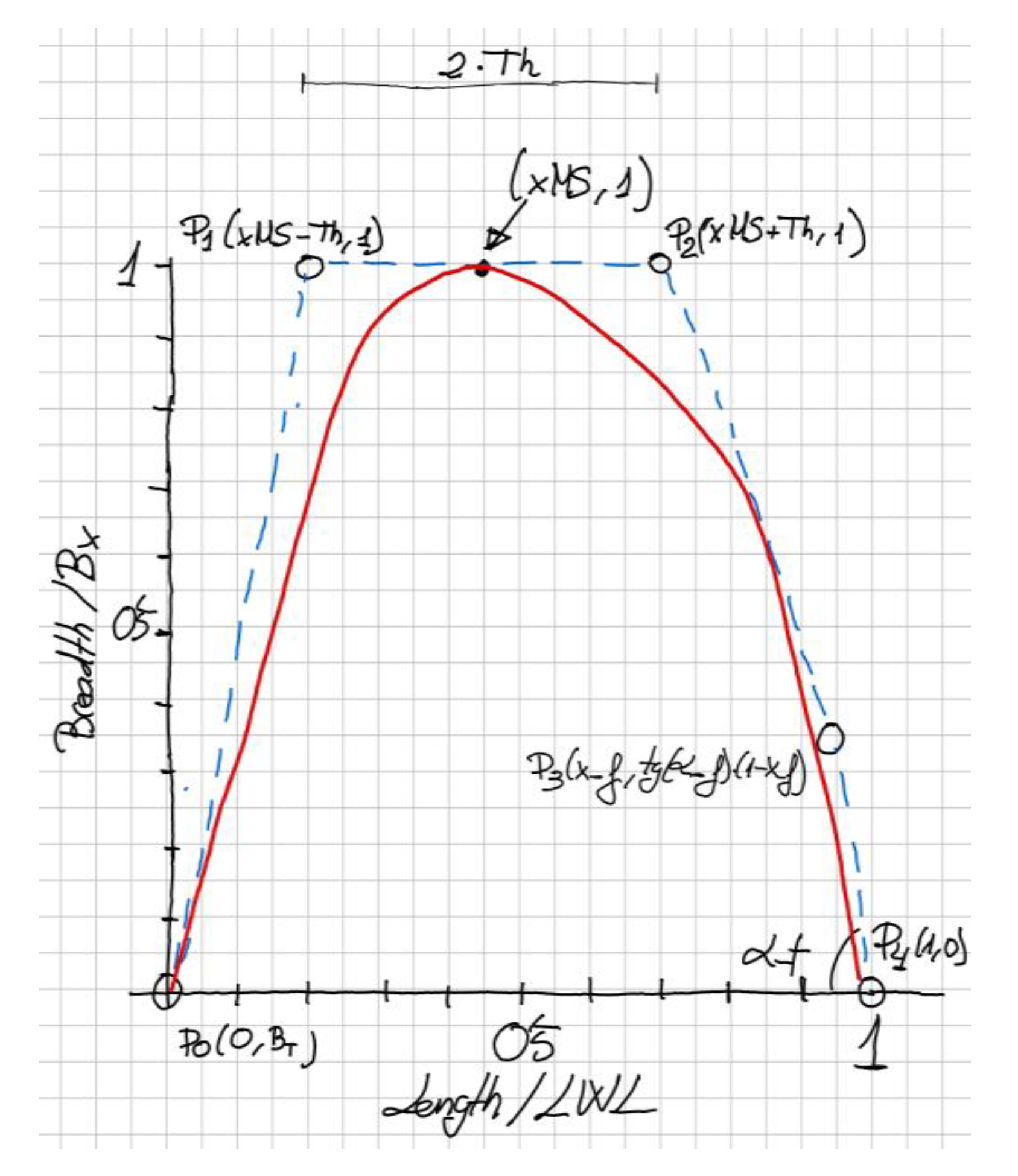
A similar optimization scheme to Figure 2 is used for the waterplane, as depicted in Figure 7. The curve is expressed in uniform form, dividing the breadth values by the maximum waterplane breadth Bx and all the abscissas by LWL, so the curve is contained into a square of 1 by 1. As in the case of the SAC, the enclosed area is equal to a non-dimensional parameter well known to the naval architect: the waterplane coefficient Cw, see Equation (3):
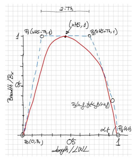
Figure 7.
Sketch for the constrained design of the Waterplane.
As in the case of the SAC, the curve is a second-degree B-spline curve and the notation of Figure 7 is the same as in Figure 2, except BT which is the submerged transom beam. The rest of the coefficients that define the control points of the B-spline are named the same.
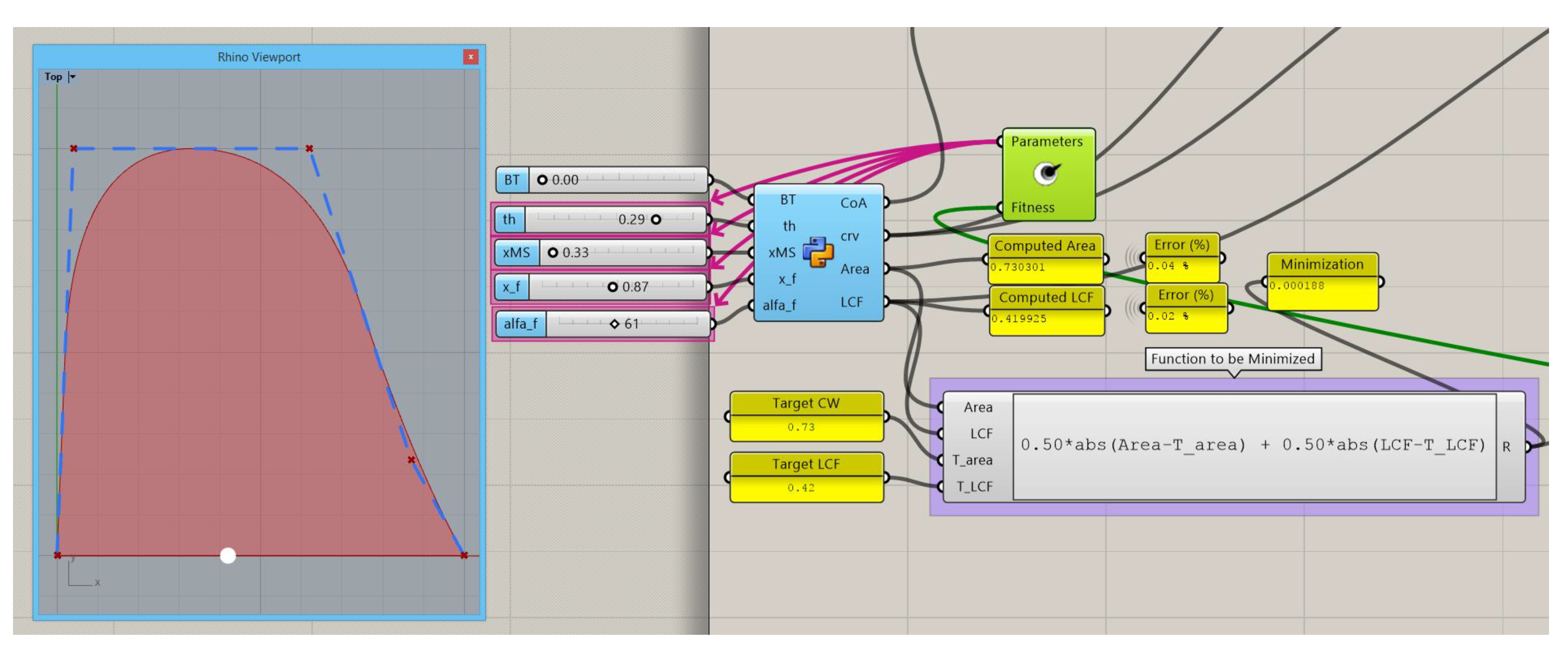
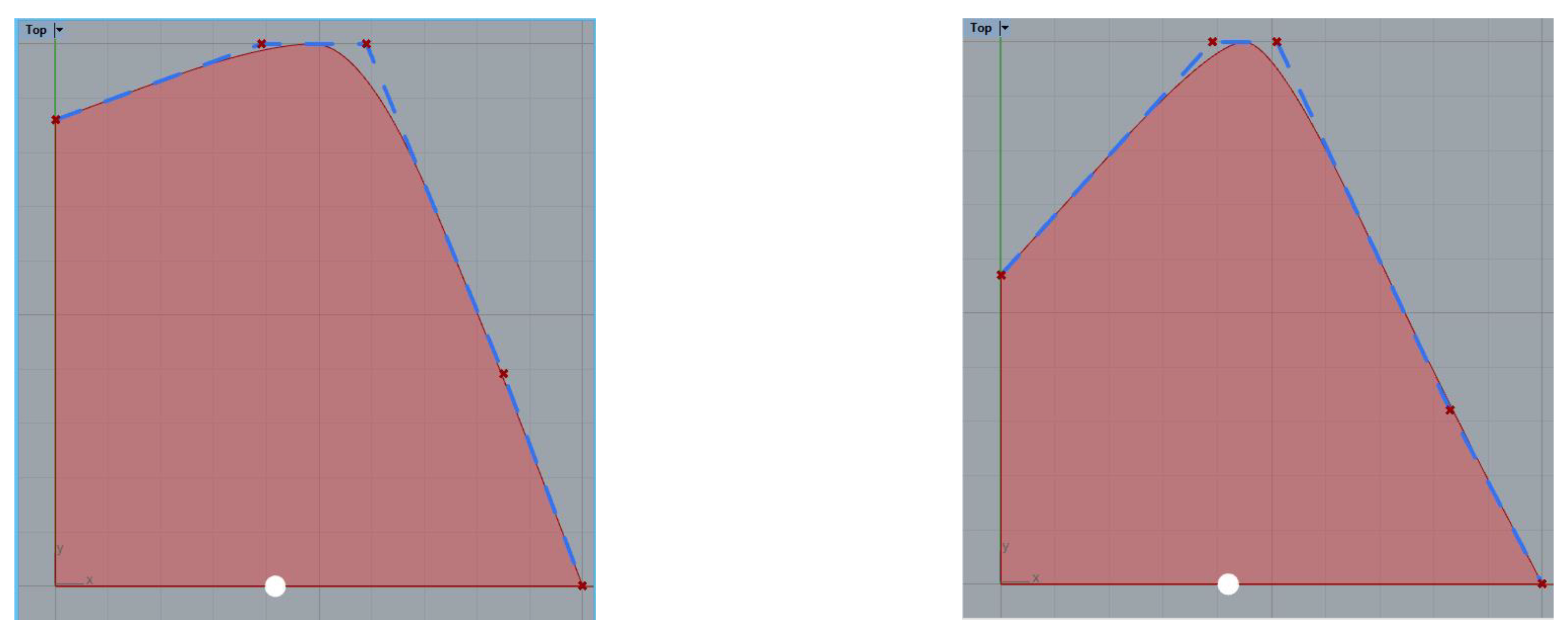
The algorithm in Grasshopper appears in Figure 8 and sets a Cw and LCF with good precision. For this example, the waterplane presents a convex shape at the bow, that will produce convex waterlines in the forepart of the ship.
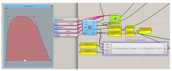
Figure 8.
DWL optimization to get a target Cw (0.73) and LCF (0.42), no transom.
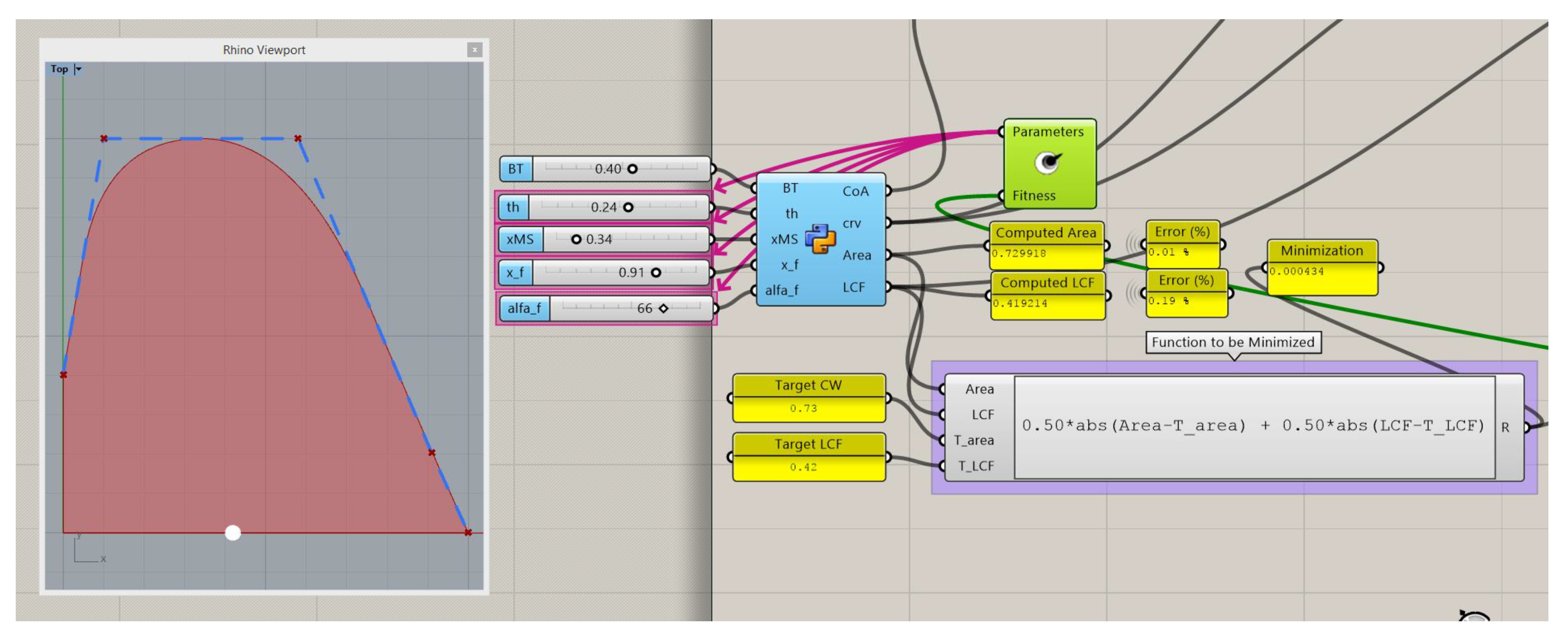
This can be corrected by increasing the area at this zone, but if the Cw and LCF have to be maintained, the only way to do this is to also increase the area at the aft end and reduce from the mid part of the ship. The mentioned procedure may render it very difficult to perform manually without a parametric definition of the waterplane, or with the standard Lackenby transformations, so it will require manual work on the ship hull. The solution to this problem is shown in Figure 9, where a transom breadth BT has been fixed and the algorithm reduces the area in the middle and increases in the fore in part to maintain the Cw and LCF.
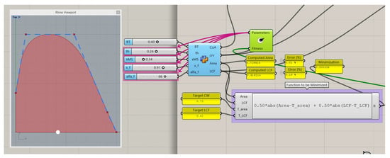
Figure 9.
DWL optimization to get a target Cw (0.73) and LCF (0.42), breadth at transom fixed.
In the next section, the paper will continue describing the parametric way to define the ship’s stations that enclose a submerged area obtained from the SAC and with a breath at the design draft T that comes from the DWL.
3. Parametric Definition of the Ship’s Stations
In the previous section, the SAC and the DWL curves of the ship have been parametrically computed, containing the ship’s main parameters and hydrodynamic coefficients. A third curve is needed to define the longitudinal profile without appendages. This centerline profile can be directly selected by the designer from other ships or from a preliminary general arrangement if available, and it is easily drawn in the CAD software.
This profile has to be smooth and with the same LWL used in the parameterization of the sectional and half-breadths curves. With this set of three curves forming the basis of the submerged hull, a suitable formulation to describe the shape of the stations has to be defined. This formulation must comply with an area imposed by the SAC, a beam imposed by the DWL, and with the station base point imposed by the centerline profile.
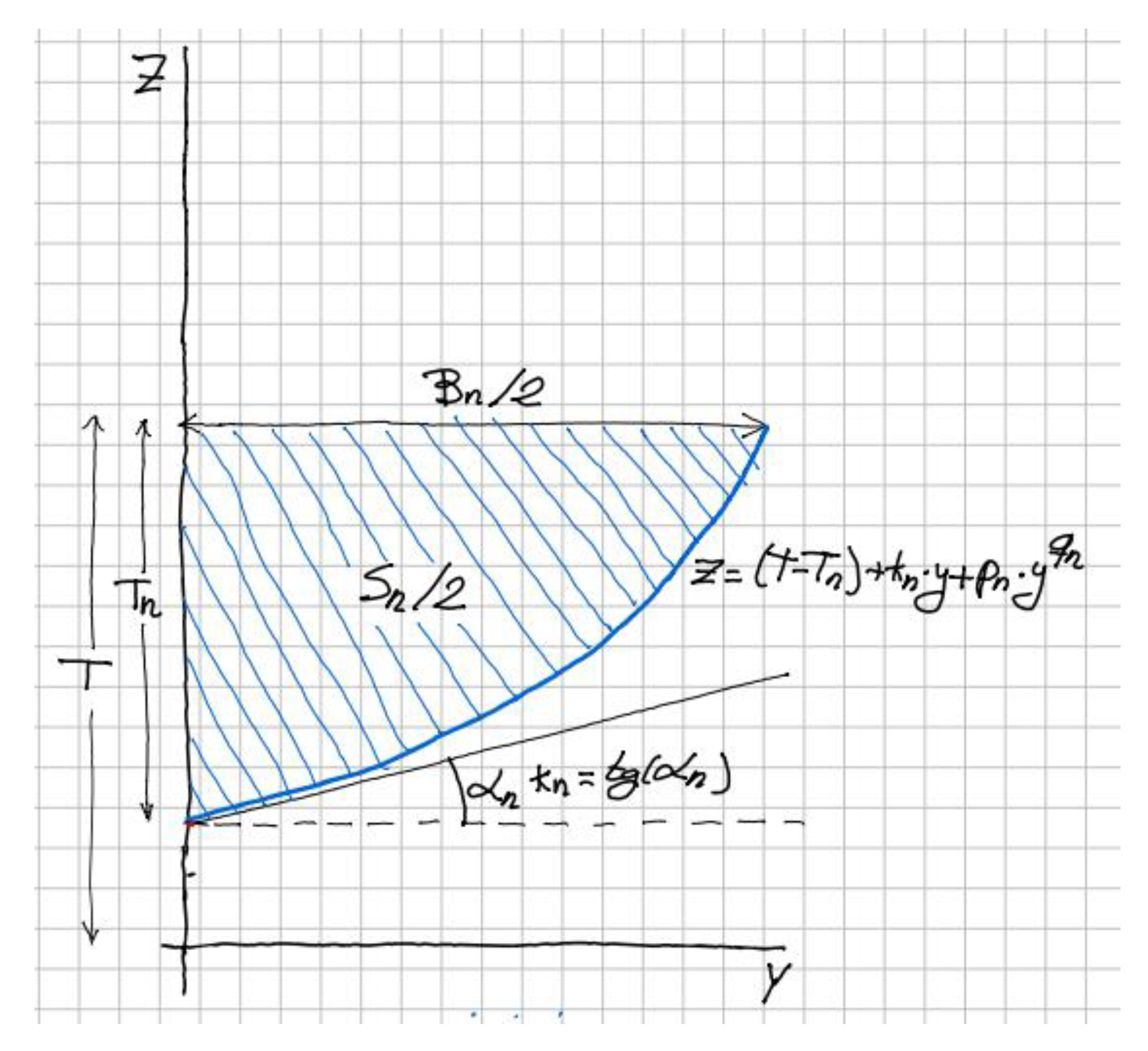
For any submerged part of a station n, this mathematical expression is selected:
In this equation, z is the ordinate measured from the baseline, y is the distance to the center plane, kn is the tangent at midship (also called deadrise angle), T is the design draft, and Tn is the draft at the nth station, meaning the distance from the waterplane to the lowest point of the station, measured from the profile curve. A sketch of such a curve is depicted in Figure 10.
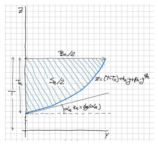
Figure 10.
Sketch for the definition of a submerged station.
The reason for this definition lies in the addition of a straight part, kn · y, that defines the shape starting from the center plane, and a curved zone, pn · yqn, that rises from the straight zone to match the corresponding beam in the waterplane. The values for coefficients pn and qn will be obtained for any station n, assigning z = T and y = Bn/2, where Bn is the value of waterline breadth, obtained from the DWL defined in Section 2.
In addition, the hatched area enclosed by the station with the flotation and the center plane must be equal to Sn/2, where Sn is obtained from the SAC defined previously. These two conditions lead to the set of Equation (5):
Notice that the sectional area and breadths curves are nondimensional and their values have to be multiplied by Ax and Bx to obtain the values of An and Bn used in the definition of the submerged stations. Notice that Equation (4) produces a discrete set of data points for the underwater part of the stations. Once they have been computed, an interpolated B-spline is constructed through them (using the rs.AddInterpCurve() function). This function allows the selection of the knot style and degree as the command InterpCrv in Rhinoceros. An uniform knot style works well for the cases that have been tested.
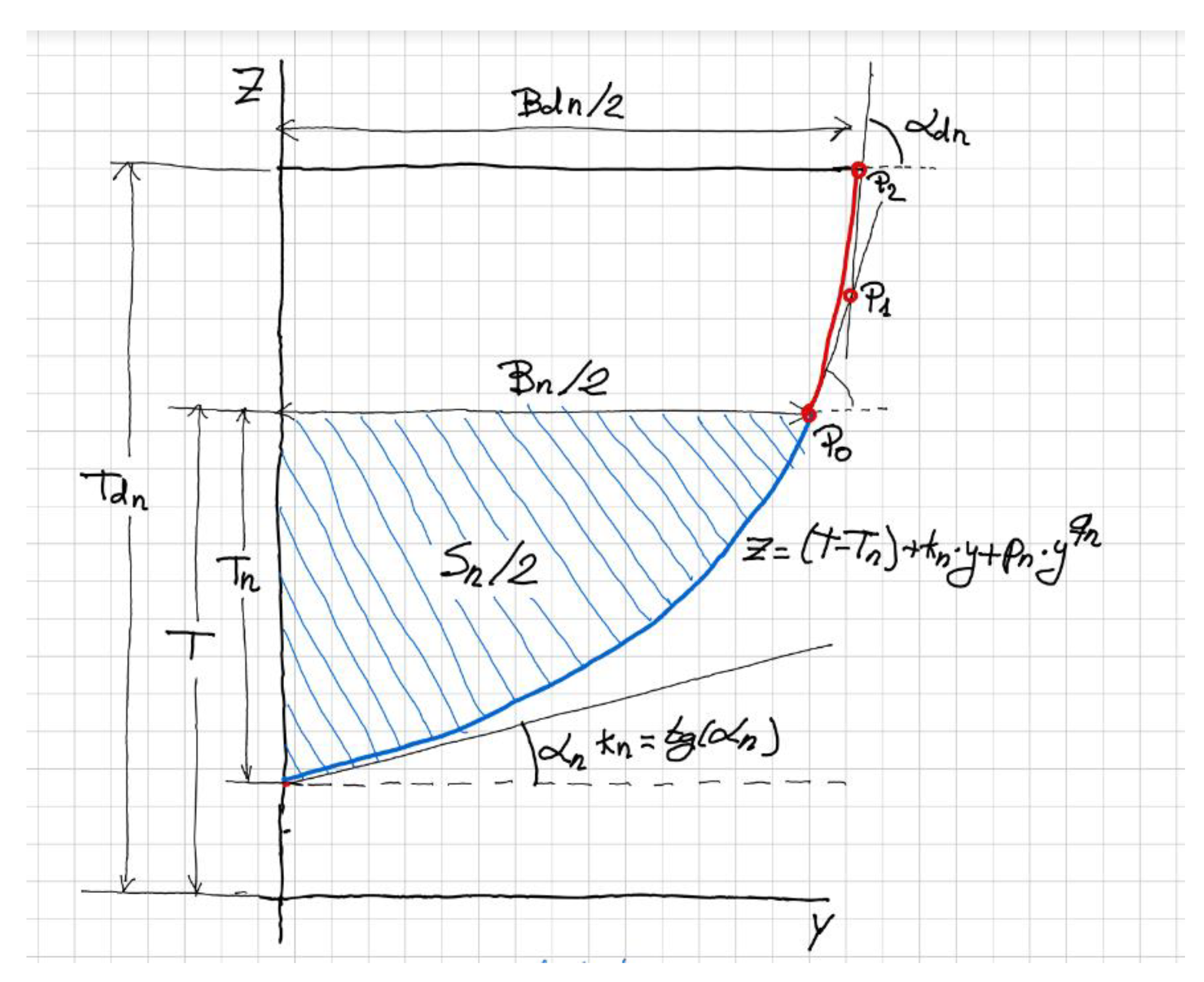
Up to now, only the underwater hull shape is defined. This is enough to perform simple numerical optimizations (i.e., linear free surface calculations) by varying the hull main coefficients, obtaining the hull very quickly in the CAD software. For a more realistic approach to the design or calculations with a non-linear free surface condition, it is necessary to define the hull shape with its part above the water. There are several options to connect the DWL part of the stations with the deck line or sheer (Bdn), usually a three-dimensional curve drawn by the designer directly in the CAD software in a similar way to the centerline profile.
For the part of the ship above water, a B-spline of the 2nd degree with three control points is used as depicted in red in the sketch of Figure 11. The first control point P0 is placed in the DWL and is the end of the underwater station with the tangent direction provided by the derivative of Equation (4). The third and last point of the B-spline P2 is placed in the deck at a given height Tdn, and with a given half breadth at the Deck Bdn. The methodology enables the selection of the flare angle at the deck measured in a transverse plane, αdn. The intersection of the two lines starting at P0 and at P2 and with the described angles produces the second point of the B-spline P1, so the curve is defined once the three control points are known.
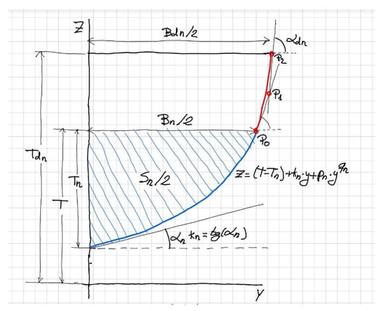
Figure 11.
Sketch for the definition of the nth station.
Once the above water station has been defined, it can be joined to the underwater part that has been defined through the discrete points defined following Equation (4) defining a single B-spline curve. Then, a lofting surface can be created containing the different B-splines that define the stations, as will be shown in the examples.
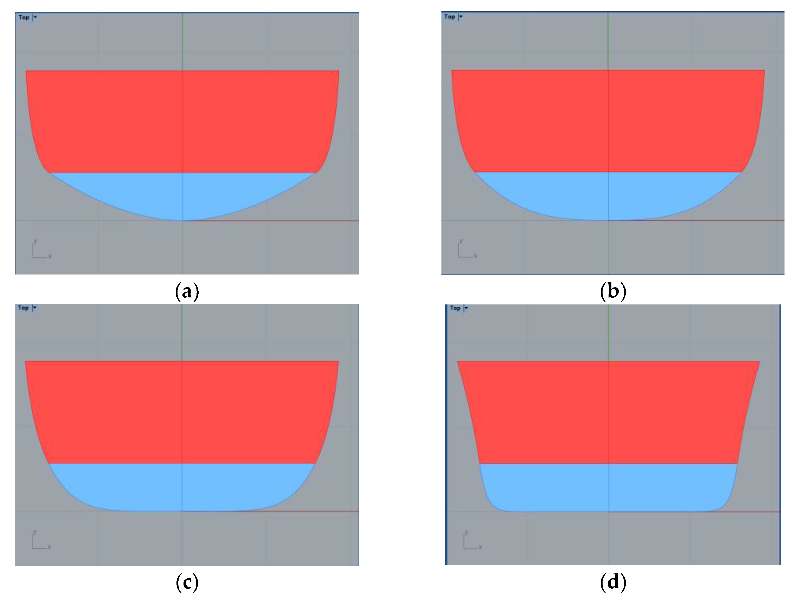
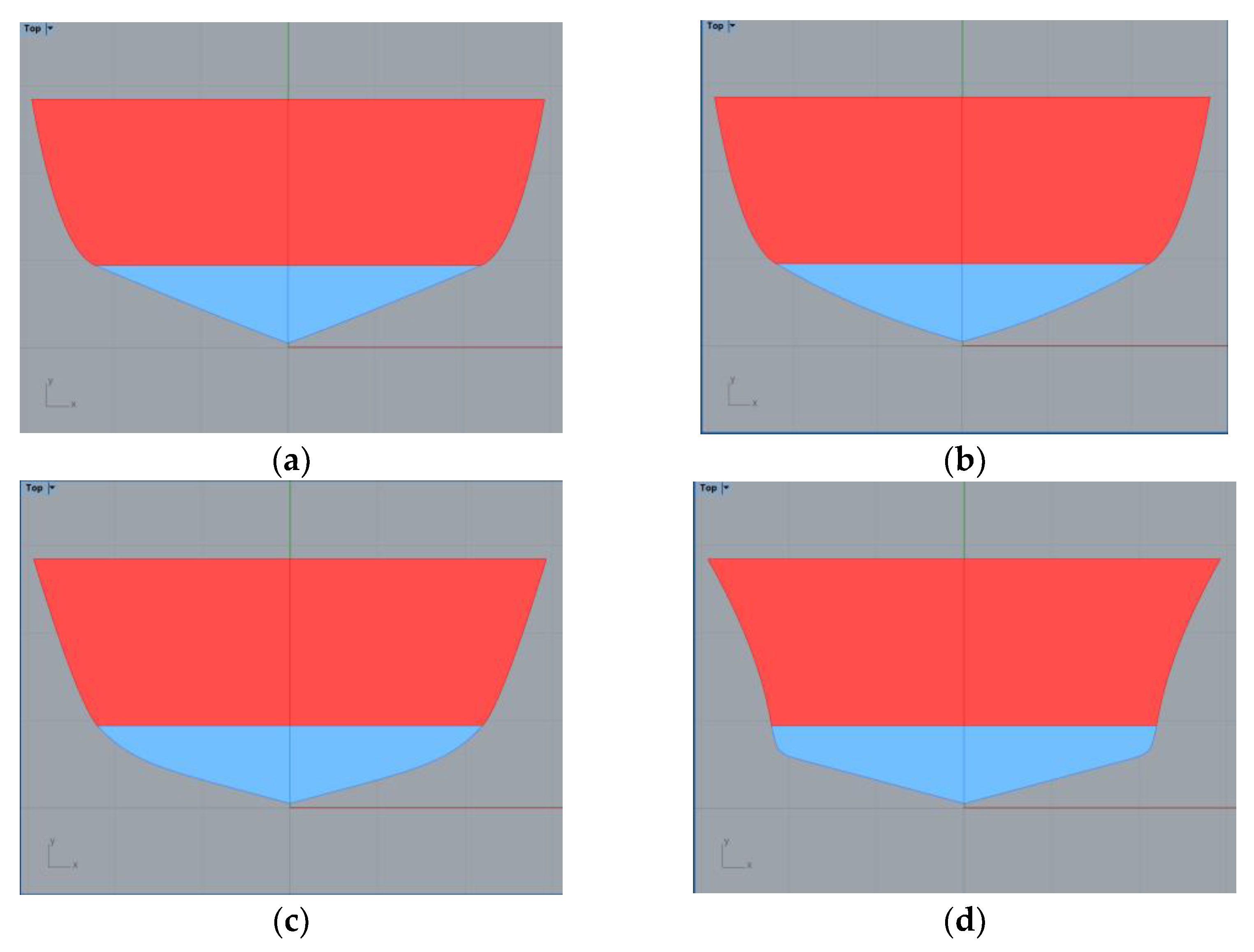
The following figures present some examples of the different shapes that can be obtained by playing with the parameters that define a station. The pictures show a sectional area coefficient defined as Ca by dividing the sectional area by the sectional draft Tn and breadth Bn, so Ca = Sn/(Tn · Bn). For all the figures, the breadth and height of the deck are maintained constant.
In these pictures, the underwater part of the station appears in blue. The maximum Ca that may be achieved is 0.95 (as in Figure 12d) and can rise until a minimum Ca of about 0.50 (as in Figure 13a). By playing with the value of the flare angle at the deck, convex shapes may be obtained (as in Figure 13d).
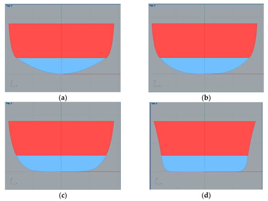
Figure 12.
Examples of stations without deadrise angles. (a) Ca = 0.65 (b) Ca = 0.75 (c) Ca = 0.85 (d) Ca = 0.95.
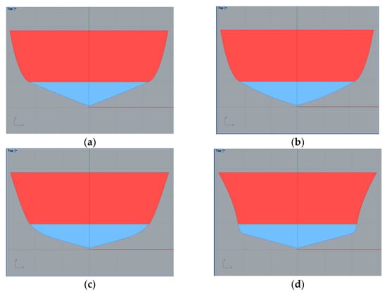
Figure 13.
Examples of stations with deadrise angles = 15°. (a) Ca = 0.51 (b) Ca = 0.56 (c) Ca = 0.62 (d) Ca = 0.66.
The following sections present two different application examples. Although the presented methodology is limited to ship hulls without a bulbous bow and with simple sterns, there are many hull forms in which this method can be used.
4. Example 1: Sailing Ship
A sailing cruiser of 24 m in length with the dimensions of Table 1 is presented without a deadrise angle in its stations. For this ship, comfort aspects are more important than sailing capabilities because during an important part of the operational profile, the ship is driven by motor. The shape of the hull is a round one that mimics the shape of a cylinder in order to minimize the wetted surface, maximizing the displacement and hence the ship’s internal volume.

Table 1.
Parameters for the sailing cruiser.
The ship’s parameters were selected according to the Delft systematic series [28], for a given speed of 9.5 knots. This series suggests optimum or nearly optimum parameters based on towing tank tests. Displacement was obtained by studying the influence of Lwl/∇^1/3 in the residuary resistance from reference [29]. The value of this ratio was taken as 5.5. Greater values will produce a faster ship but will reduce the comfort and seakeeping properties. The generated waterline should consider the internal volume distribution, based on an initial volume study of the internal arrangement of the design. The same consideration can be made for the deck parameters. Maximum breath is calculated considering sail area and stability parameters. This way, Awp, Bx, and LCF are obtained.
Applying the parametric methodology for the SAC and DWL explained in Section 2, the curves of Figure 14 are obtained. Notice that these curves are uniform in [0,1] and have to be multiplied by Ax and Bx to produce the appropriate dimensions to obtain the area and breadths that are necessary for the parametric definition of the ship’s stations.
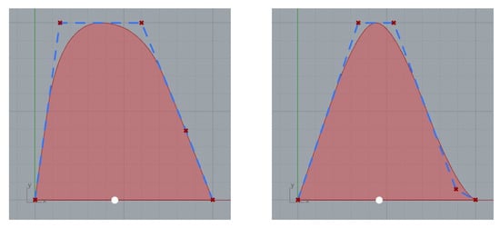
Figure 14.
Non-dimensional curves for the DWL and SAC of the Sailing Ship.
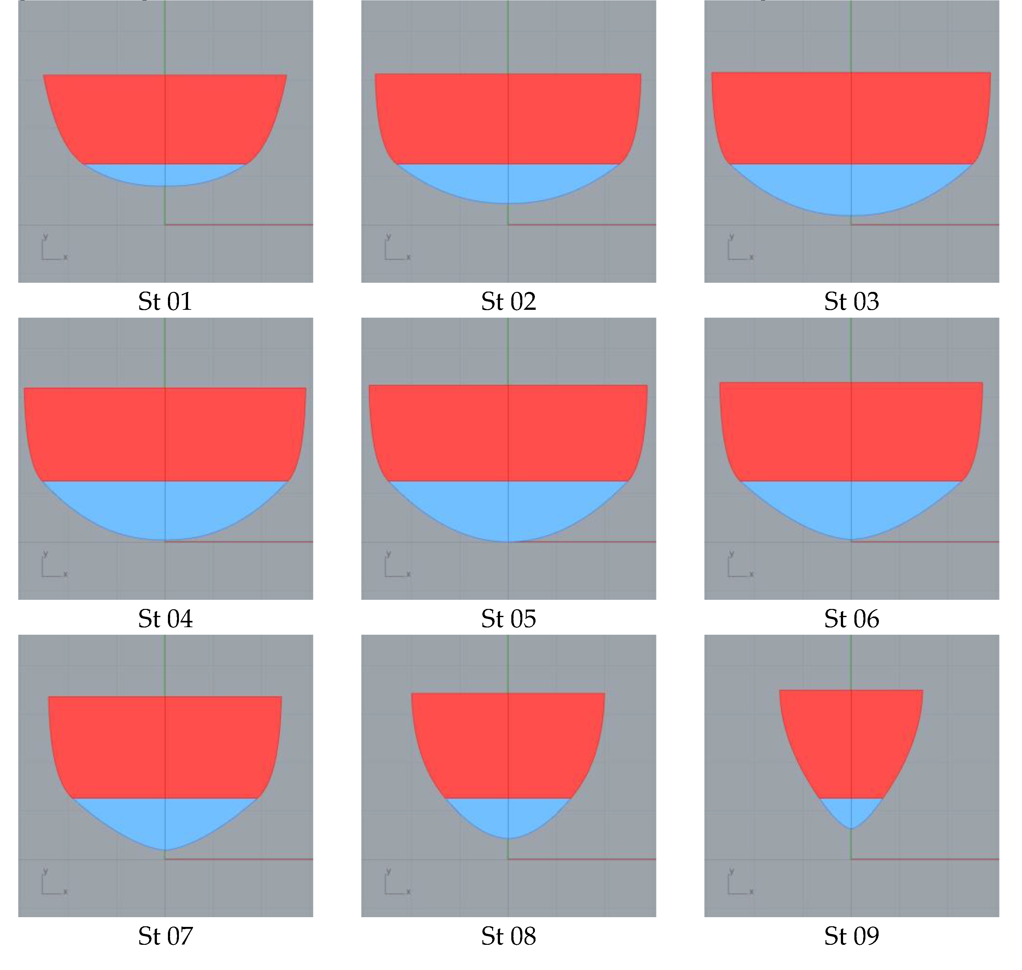
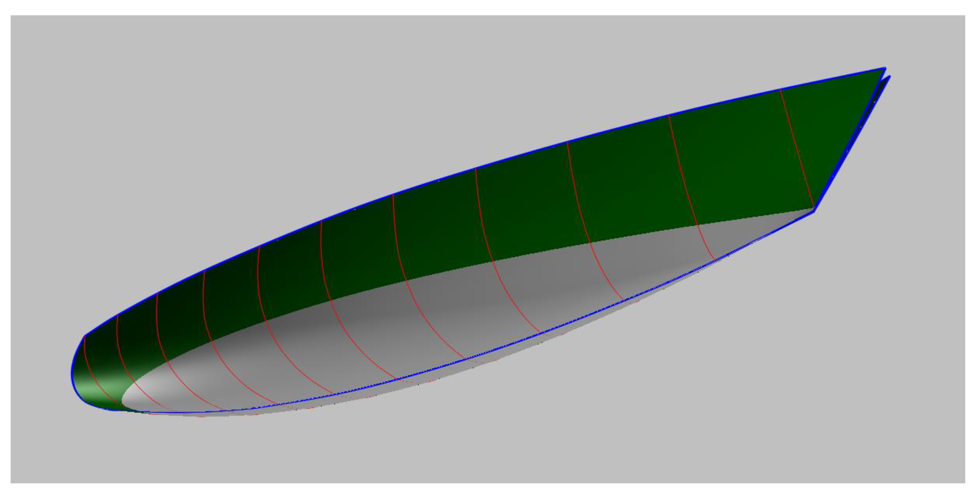
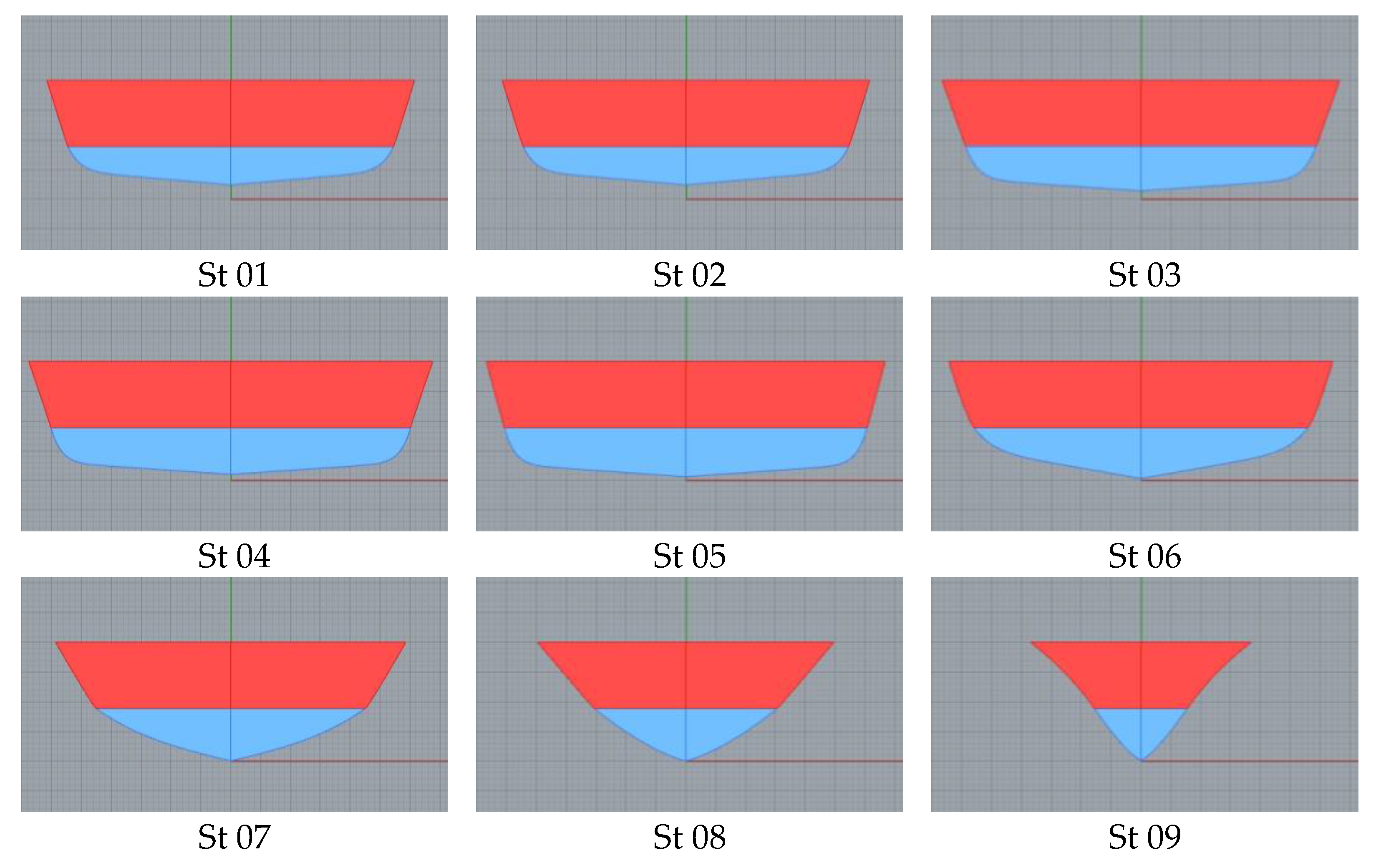
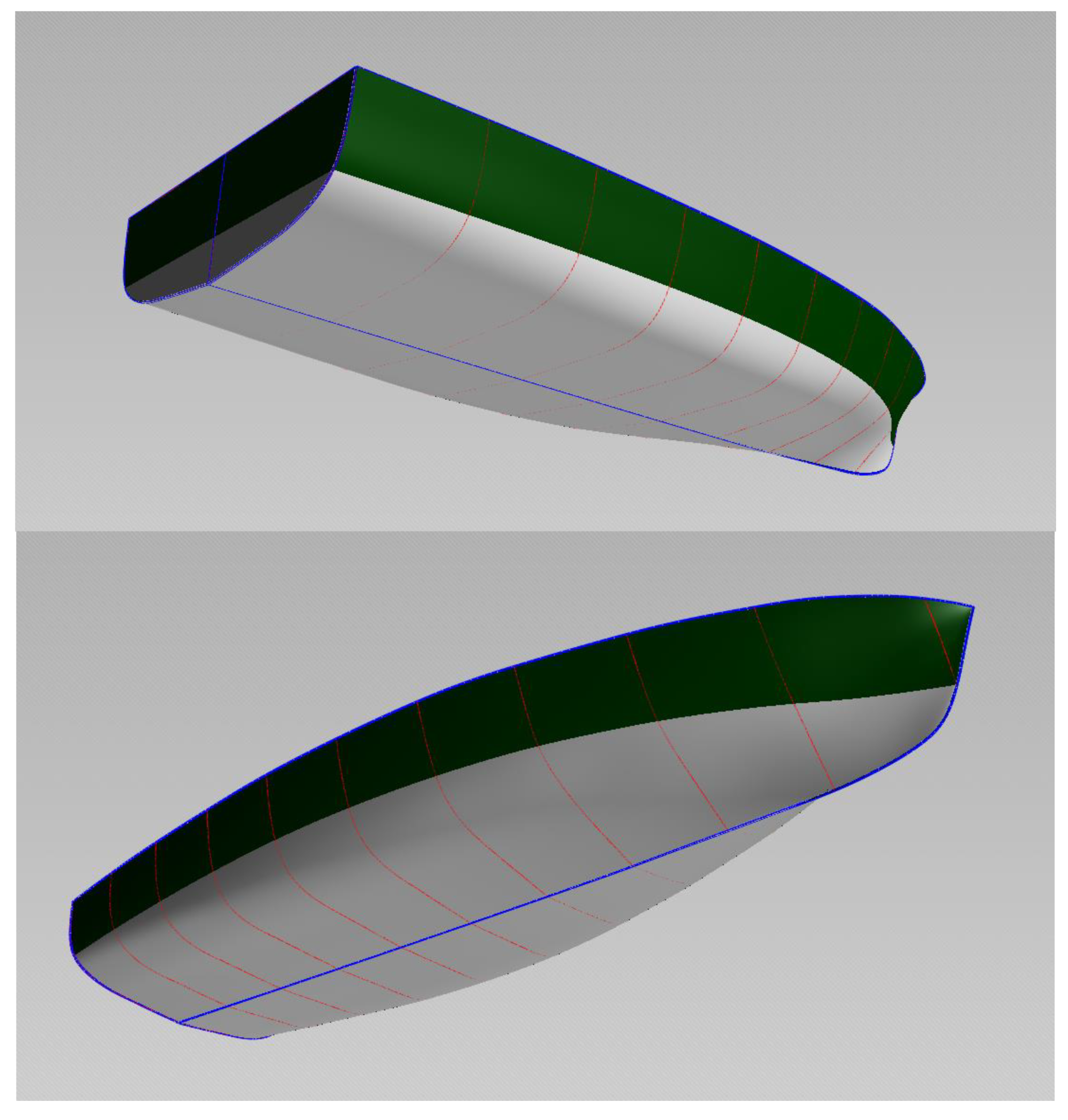
The ship’s stations are computed according to Section 3, once the SAC and DWL of Figure 14 have been obtained. The design waterline is divided into ten equal parts, and the stations from 01 until 09 are presented in Figure 15. For St 0 and St 10 that are not showed in this figure and have a zero value for the submerged area and breadth, the B-splines over the water of stations 1 and 9 are used. The basic curves Center line and Deck line are designed to accommodate the internal arrangement and can be seen in Figure 16, together with the surface that contains the stations of Figure 15.
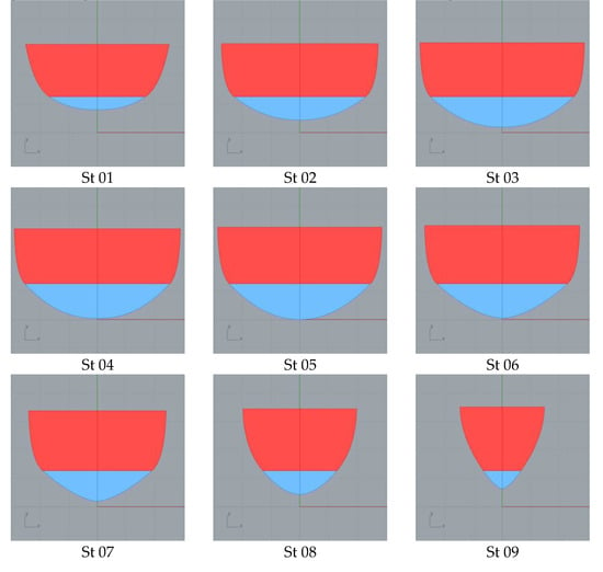
Figure 15.
Sections for the Sailing Ship.
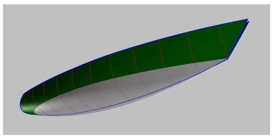
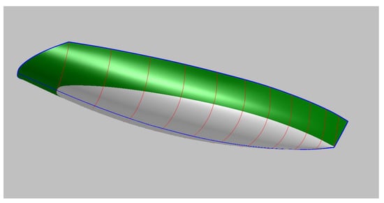
Figure 16.
D view of the Sailing Ship.
5. Example 2: High Speed Craft
This second example presents a round-bilged high-speed vessel with a transom stern, designed to operate in shallow water with a reduced draft, and a slightly higher block coefficient (Cb = 0.51) in order to accommodate a water jet propulsion system. Parameters of this example are showed in Table 2. The example is based on the NOVA systematic series [30] which is a modification of the model 100A of the NPL series [31]. The coefficients were selected in the range proposed by the NOVA series. Deadrise angle varies from 4 degrees in the mid-section and 5 degrees in the transom, with a linear variation between stations for the NOVA series. The variation of the deadrise angle along the stations is selected by the user.

Table 2.
Parameters for the high-speed craft.
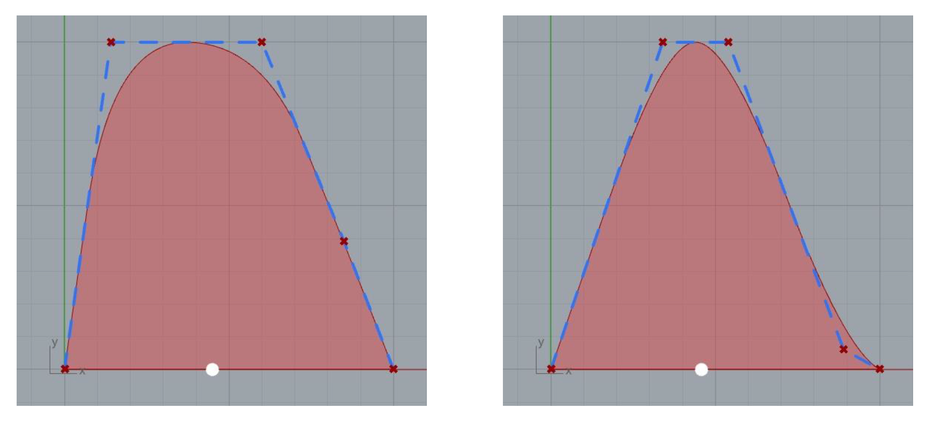
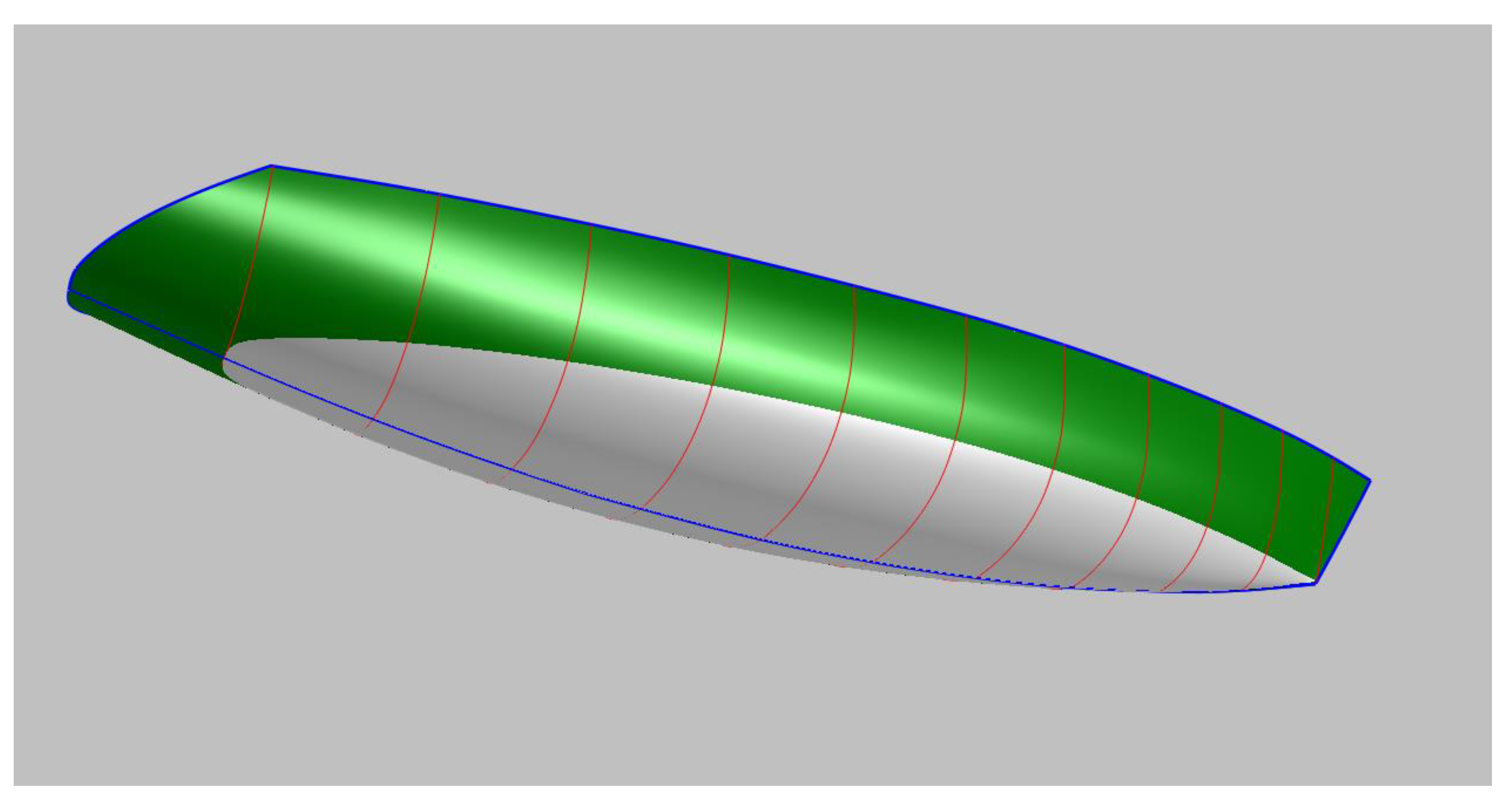
Applying Section 2, the non-dimensional DWL and SAC of Figure 17 are obtained. With information on these two curves and following Section 3, the different stations of Figure 18 are computed. The Center line and Deck line curves follow the NOVA series and can be seen in Figure 19 together with the surface that contains the stations of Figure 18.
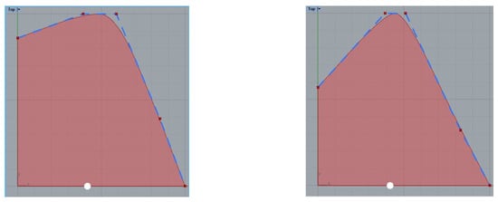
Figure 17.
Non-dimensional curves for the DWL and SAC of the High-Speed Craft.
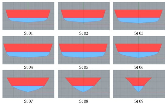
Figure 18.
Sections for the High-Speed Craft.
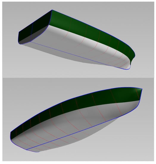
Figure 19.
Three-dimensional view of the High-Speed Craft.
6. Conclusions
This paper has presented a Parametric Approach (PA) for the definition of a ship hull, which is based on geometric parameters that are common for a naval architect and whose effect on some ship characteristics such as stability or hydrodynamics is known.
In the PA presented, there is a clear relationship between a set of basic curves, shape parameters, and section definition, so it is not difficult to use for non-experienced designers. By using this PA, the designer can create both local and global variations with the use of the design variables.
Establishing the basic or feature curves, keel and deck lines, and their relationship with the stations of the ship hull is the key to applying a PA to a ship hull form as explained in Section 3. In this paper, stations start in the keel and go through the water line until the deck line. The keel and deck lines have been sketched by the user inside the CAD software with the use of B-splines and the water line has been obtained to enclose the AWP and with a centroid in LCF. This has been described in Section 2.
The presented method can provide the user with many sample ship hulls in a short time, reducing the time spent on manual modeling and improving the efficiency of the design. The fairing is achieved if smooth curves are used for the keel and deck, together with a gentle distribution of the deadrise and flare angles along the ship’s length.
The ship hull representation needs to be accurate to produce a faired set of surfaces, enabling the generation of geometric variations of the hull in an easier way, e.g., with a reduced number of parameters or inputs, with a clear meaning between the numerical parameter, and induced surface modification. A key design feature to accelerate the design process is using a flexible/parametric method to design an initial hull that also enables the modification of the shape in the next phases.
In order to cover different types of ship hulls, PA may contain a large number of scalar parameters. In the presented methodology, this is avoided by defining some of the basic curves of the hull drawing directly in the CAD software. This simplifies the definition of the PA and produces more flexibility in the design process.
Finally, the presented PA is limited as these kinds of methodologies cannot be considered universal methods for ship design. In this paper, parametric generation of hull lines is applied to simple hull forms such as round bilge hulls, normally used in small patrol boats, some small fishing vessels, or sailing ships. These lines are suitable for this method as far as they have no bow bulbs, integrated skegs, or other complex parts that are common in large ships.
Planning boats with sharp edges (chines) are also outside of the scope of this paper since their stations cannot be well reproduced with Equation (4). An extension of the present paper could consider the modification of the SAC or WL to include a cylindrical body that maintains the station’s shape in the central part of the ship.
Funding
This research received no external funding.
Institutional Review Board Statement
Not applicable.
Informed Consent Statement
Not applicable.
Data Availability Statement
Data available upon request to the author.
Conflicts of Interest
The author declares no conflict of interest.
References
- Papanikolaou, A. Holistic ship design optimization. Comput. Aided Des. 2010, 42, 1028–1044. [Google Scholar] [CrossRef]
- Nikolopoulos, L.; Boulougouris, E. A methodology for the holistic, simulation driven ship design optimization under uncertainty. In Marine Design XIII, 1st ed.; CRC Press: Boca Raton, FL, USA, 2018. [Google Scholar]
- Lamb, T. Ship Design and Construction; Society of Naval Architects and Marine Engineers: Jersey City, NJ, USA, 2004; Volume 4. [Google Scholar]
- Harries, S. Parametric Design and Hydrodynamic Optimization of Ship Hull Forms; Mensch-und-Buch-Verlag: Berlin, Germany, 1998. [Google Scholar]
- Harries, S.; Abt, C. Parametric curve design applying fairness criteria. In Proceedings of the International Workshop on Creating Fair and Shape Preserving Curves and Surfaces, Kleinmachnow, Germany, 14–17 September 1997. [Google Scholar]
- Nowacki, H.; Liu, D.; Lü, X. Fairing bézier curves with constraints. Comput. Aided Geom. Des. 1990, 7, 43–55. [Google Scholar] [CrossRef]
- Brenner, M.; Zagkas, V.; Harries, S.; Stein, T. Optimization using viscous flow computations for retrofitting ships in operation. In Proceedings of the V International Conference on Computational Methods in Marine Engineering, Hamburg, Germany, 29–31 May 2013. [Google Scholar]
- Brizzolara, S.; Vernengo, G.; Pasquinucci, C.A.; Harries, S. Significance of parametric hull form definition on hydrodynamic performance optimization. In Proceedings of the VI International Conference on Computational Methods in Marine Engineering, Rome, Italy, 15–17 June 2015; pp. 254–265. [Google Scholar]
- Kuiper, G. Preliminary design of ship lines by mathematical methods. J. Ship Res. 1970, 14, 52–66. [Google Scholar] [CrossRef]
- Kim, H.; Nowacki, H. Parametric Design of Complex Hull Forms. J. Ship Ocean. Technol. 2005, 9, 47–63. [Google Scholar]
- Pérez, F.; Suárez, J.; Clemente, J.; Souto, A. Geometric modelling of bulbous bows with the use of non-uniform rational B-spline surfaces. J. Mar. Sci. Technol. 2007, 12, 83–94. [Google Scholar] [CrossRef]
- Birk, L.; McCulloch, T.L. Robust generation of constrained B-spline curves based on automatic differentiation and fairness optimization. Comput. Aided Geom. Des. 2018, 59, 49–67. [Google Scholar] [CrossRef]
- Zhang, P.; Leng, W.; Zhu, D.; Huang, S. Parametric modeling approach of hull form. J. Ship Mech. 2009, 13, 47–54. [Google Scholar]
- Nam, J.-H.; Parsons, M. A Parametric approach for initial hull form modeling using NURBS representation. J. Ship Prod. 2000, 162, 76–89. [Google Scholar] [CrossRef]
- Nam, J.H.; Bang, N.S. A curve based hull form variation with geometric constraints of area and centroid. Ocean. Eng. 2017, 133, 1–8. [Google Scholar] [CrossRef]
- Sariöz, E. An optimization approach for fairing of ship hull forms. Ocean. Eng. 2006, 33, 2105–2118. [Google Scholar] [CrossRef]
- Xing, Y.; Papanikolaou, A. Optimization of the Propulsive Efficiency of a Fast Catamaran. J. Mar. Sci. Eng. 2021, 9, 492. [Google Scholar] [CrossRef]
- Zhou, H.; Feng, B.; Liu, Z.; Chang, H.; Cheng, X. NURBS-Based Parametric Design for Ship Hull Form. J. Mar. Sci. Eng. 2022, 10, 686. [Google Scholar] [CrossRef]
- Vernengo, G.; Villa, D.; Gaggero, S.; Viviani, M. Interactive design and variation of hull shapes: Pros and cons of different CAD approaches. Int. J. Interact. Des. Manuf. 2020, 14, 103–114. [Google Scholar] [CrossRef]
- Pérez-Arribas, F.; Calderon-Sanchez, J. A parametric methodology for the preliminary design of SWATH hulls. Ocean. Eng. 2020, 197, 106823. [Google Scholar] [CrossRef]
- Koelman, H.J.; Horváth, I.; Aalbers, A. Hybrid representation of the shape of ship hulls. Int. Shipbuild. Prog. 2001, 48, 247–269. [Google Scholar]
- Choi, H.J. Hull-form optimization of a container ship based on bell-shaped modification function. Int. J. Nav. Archit. Ocean. Eng. 2015, 7, 478–489. [Google Scholar] [CrossRef]
- Coppedé, A.; Vernengo, G.; Villa, D. A combined approach based on subdivision surface and free form deformation for smart ship hull form design and variation. Ships Offshore Struct. 2018, 13, 769–778. [Google Scholar] [CrossRef]
- Nahm, Y.-E.; Ishikawa, H. Representing and aggregating engineering quantities with preference structure for set-based concurrent engineering. Concurr. Eng. 2005, 13, 123–133. [Google Scholar] [CrossRef]
- Singer, D.J.; Doerry, N.; Buckley, M.E. What is set-based design? Nav. Eng. J. 2009, 121, 31–43. [Google Scholar] [CrossRef]
- Perez, F.; Clemente, J.A. Constrained design of simple ship hulls with b-spline surfaces. Comput. -Aided Des. 2011, 43, 1829–1840. [Google Scholar] [CrossRef]
- Cichocka, J.; Migalska, A.; Browne, W.; Rodriguez-Ramirez, E. SILVEREYE—The Implementation of Particle Swarm Optimization Algorithm in a Design Optimization Tool. In Computer-Aided Architectural Design, Proceedings of the Computer-Aided Architectural Design. Future Trajectories: 17th International Conference, CAAD Futures 2017, Istanbul, Turkey, 12–14 July 2017; Springer: Singapore, 2017; pp. 151–169. [Google Scholar]
- Gerritsma, J.; Keuning, J.A.; Versluis, A. Sailing Yacht Performance in Calm Water and in Waves. In Proceedings of the The 11th Chesapeake Sailing Yacht Symposium, Annapolis, MD, USA, 29–30 January 1993. [Google Scholar]
- Larsson, L.; Eliasson, R. Principles of Yacht Design; Adlard Coles Nautical: London, UK, 1994. [Google Scholar]
- Lahtiharju, E.; Karppinen, T. Resistance and Seakeeping Characteristics of Fast Transom Stern Hulls with Systematically Varied Form. Trans. Soc. Nav. Archit. Mar. Eng. 1991, 99, 85–118. [Google Scholar]
- Bailey, D. The NPL High Speed Round Bilge Displacement Hull Series. Maritime Technology 4; Society of Naval Architects and Marine Engineers (SNAME): Alexandria, VA, USA, 1976. [Google Scholar]
Disclaimer/Publisher’s Note: The statements, opinions and data contained in all publications are solely those of the individual author(s) and contributor(s) and not of MDPI and/or the editor(s). MDPI and/or the editor(s) disclaim responsibility for any injury to people or property resulting from any ideas, methods, instructions or products referred to in the content. |
© 2023 by the author. Licensee MDPI, Basel, Switzerland. This article is an open access article distributed under the terms and conditions of the Creative Commons Attribution (CC BY) license (https://creativecommons.org/licenses/by/4.0/).

