Article

Experimental Study on Hydrodynamic Characteristics of a Submerged Floating Tunnel under Freak Waves (I: Time-Domain Study)

1
National Engineering Research Center of Port Hydraulic Construction Technology, Tianjin Research Institute for Water Transport Engineering, Ministry of Transport of the People’s Republic of China, Tianjin 300456, China
2
State Key Laboratory of Coastal and Offshore Engineering, Dalian University of Technology, Dalian 116024, China
*
Author to whom correspondence should be addressed.
J. Mar. Sci. Eng. 2023, 11(5), 977; https://doi.org/10.3390/jmse11050977
Submission received: 15 March 2023 / Revised: 19 April 2023 / Accepted: 28 April 2023 / Published: 4 May 2023

Abstract

:
The dynamic response characteristics of a two-dimensional submerged floating tunnel (SFT) under random and freak waves were investigated in the present study. The results demonstrate that (1) the dynamic responses of the SFT under the freak wave are significantly larger than those under the largest wave in the wave train excluding the freak wave, particularly for the motion response. The maximum values of the motion responses induced by the freak wave were several times larger than those induced by the largest wave in the wave train excluding the freak wave, far exceeding the proportion of the corresponding wave height. (2) The freak wave parameter α1 has a significant effect on the amplification coefficients of surge, heave and pitch; all increase nonlinearly as α1 increases. Within α1 = 1.90~2.59, the amplification coefficients of the surge, heave and pitch vary in the ranges of 1.91~6.46, 1.53~3.87 and 1.73~5.32, respectively. (3) Amplification coefficients of tension increase almost linearly as α1 increases. Additionally, the amplification effect of the freak wave on the mooring tension is much smaller than that on motion responses. Within α1 = 1.90~2.59, the amplification coefficients of tension vary from 1.15 to 1.35. (4) Generalised amplification coefficients of motion responses increase as α1 increases and are all greater than 1.0, indicating that growth rates for motion responses under the freak wave exceed the growth rates for maximum wave height. Moreover, motion responses show a significantly nonlinear growth as maximum wave height increases. The generalised amplification coefficients of the mooring tension decrease as α1 increases, and are all less than 1.0, indicating that the dynamic amplification effect of the freak wave on the mooring tension is much smaller than that on motions. On the other hand, growth rates of the mooring tension under freak waves are smaller than the linear growth rate of the height of freak waves.

1. Introduction

In recent decades, more and more occurrences of freak waves have been recorded and reported in oceanographic observations globally [1]. In the meantime, many maritime accidents demonstrate that freak waves are a serious hazard to offshore vessels and structures [2]. Numerous studies have been conducted on the freak wave, including the definition and external characteristics, generation mechanisms, probability of occurrence, numerical simulation, physical model experimental techniques [3,4,5,6,7] and freak wave-structure interactions.
To study the interaction between the freak wave and structures, Rudman et al. [8,9] used the smoothed particle hydrodynamics (SPH) method to simulate the action of freak waves on a semi-submersible platform and compared the characteristics and similarities of the dynamic response of the semi-submersible platform moored using the Tension Leg Platform (TLP) and the Taut Spread Mooring system (TSM). Research has shown that systems moored by the two methods heave and surge in significantly different ways when subjected to freak waves. The pitch of both the systems was essentially the same; however, the TLP system generated larger surge and smaller heave than the TSM system. The total mooring force of the TSM system was approximately four times higher than that of the TLP system. Furthermore, Rudman and Cleary [10] used the SPH method to discuss the effects of wave incident angle and pretension variation on the dynamic responses of a semi-submersible tension leg platform under freak waves. The results showed that the wave incident angle had a critical effect on the peak tension and the “slack” phenomenon of the tension. In addition, the 45° incident angle caused maximum tension, which encounters the wave first, while the maximum heave, surge and pitch exhibited a weak relationship with the wave incident angle. Peak tension slightly rose as pretensions increased, but the occurrence of “slack” significantly decreased.
From 2013 to 2016, a research team at the Shanghai Jiao Tong University conducted a series of studies on the impact of freak waves on floating structures [11,12,13,14,15]. Gu et al. [11] chose a modified method, superposing random waves and transient waves, to simulate a strongly nonlinear wave, the “New Year wave”. They numerically simulated the dynamic responses of a tension leg platform under the “New Year wave” and compared the similarities and differences of the time-domain dynamic characteristics induced by random and freak waves, which have the same wave spectrum. According to the findings, the motion responses and mooring tension under the “New Year wave” were larger than those under the random wave. The maximum values of the wave forces on the platform induced by the “New Year wave” in the horizontal and vertical directions increased by approximately 25% compared with those induced by random waves; whereas the surge, heave and pitch increased by approximately 33%, 38% and 12%, respectively, and the mooring tension increased by approximately 20%. Deng et al. [15] investigated the dynamic response of a semi-submersible platform under freak waves, wind and current. The freak waves had a wave height Hs of 13 m, maximum wave height Hm of 30.2 m, maximum crest ηmax of 23.17 m, and freak wave parameter α1 of 2.32. Two mooring systems corresponding to 300 and 1500 m water depth were used in the experiment, and the horizontal stiffness of the mooring system at a water depth of 300 m was significantly greater than that at a water depth of 1500 m. The results showed that for a mooring system with a lower mooring stiffness (used at a 1500-m water depth), the low-frequency characteristics of the surges significantly increased under freak waves. This is because the freak wave provides additional thrust to the semi-submersible platform to move further before being pulled back by the recovery force. However, the mooring stiffness had a considerably small effect on the heave and pitch. Freak waves may cause the anchor chains to shift from taut to slack, resulting in an extremely high tension for mooring systems with higher mooring stiffness (used at a 300-m water depth).
Pan et al. [16,17,18] conducted extensive physical model experiments to compare the differences in the dynamic responses of a moored rectangular cylinder under random and freak waves in the time, frequency, and time-frequency domains. The effects of the relative wave height, relative period, and freak wave parameters on the dynamic responses of the moored rectangular cylinder were discussed quantitatively.
With the exploitation and utilization of the ocean to the deep water, floating structures have gained increasing attention in recent years. Submerged floating tunnel (SFT) is a new type of underwater traffic structure and is considered to be one of the major transportation engineering feats for crossing deep seas. It is a forward-looking world-class scientific and technological challenge facing the future, and a leading edge of science and technology. Yang et al. [19,20] experimentally investigated the dynamic responses and hydrodynamic characteristics of a submerged floating tunnel exposed to regular waves. Li et al. [21] investigated the effects of irregular waves on three kinds of SFT structures through physical model test. Currently, most of the relevant studies focus on the hydrodynamic loads and motion responses under regular wave or conventional irregular waves.
Existing studies on the interaction between freak waves and floating structures have revealed the complexities of the dynamic responses induced by freak waves (i.e., the loads and motion responses of various types of floating structures induced by freak waves significantly exceed those induced by random waves). However, most studies have concentrated on specific types of structures which float on the water surface, such as offshore semi-submersible platforms, TSM or TLP platforms, FPSO vessels, crane vessels, and three-legged jack-up platforms. There are few studies on submerged floating structures. With the emergence of a number of ocean-related projects, such as cross-sea bridges, submarine tunnels, ocean energy generation, marine ranching, and other future-oriented frontier scientific issues, such as submerged floating tunnel (SFT), there is an increasing need for research on the dynamic responses of submerged floating bodies.
In this study, we employ a physical model experiment based on the work of Pan et al. [16,17,18] to investigate the dynamic response of a two-dimensional SFT. The dynamic response characteristics of the SFT under the freak wave in time-domain are analysed according to the time histories of the motion response and mooring tension obtained from the tests. The amplification effect of the freak wave on the dynamic response and the quantitative relationship between the freak wave parameter and the dynamic response of the SFT are explored.

2. Experiments

2.1. Experimental Equipment and Instruments

The experiment was performed in a large-wave-current flume at the State Key Laboratory of Coastal and Offshore Engineering, Dalian University of Technology. The flume had a length of 60 m, width of 2 m, and depth of 1.8 m. The wave generation system was the Hydro-servo random wave maker system and can generate waves with periods ranging from 0.5 s to 5.0 s. Multi-layer energy dissipation equipment was installed at the end of the flume to eliminate wave reflection.
The motion of moored square cylinder was measured by a contactless 6 DOF (degree of freedom) measurement system, consisting of dual-CCD cameras and a data acquisition system. To track the motions, three light markers on top of the cylinder were arranged in a plane. The images of markers were acquired continuously by the dual-CCD at 30 Hz.
The mooring tension was measured by a tension sensor with accuracy of ±0.1 N. The wave heights were collected by DS30 waves measuring system which can control 64 wave gauges synchronously.

2.2. Model Parameters and Layout

The engineering background was the submerged floating tunnel used in the conceptual design of the SFT by the China Communications Construction (CCCc) SFT Technical Joint Research Team. The outer diameter of the tunnel was 12 m and the interval between the cables along the longitudinal direction of the tunnel was 120 m. It should be noted that the SFT is considerably long (km level). A finite-length section (120 m) was intercepted and simplified into a rigid submerged horizontal cylinder for two-dimensional experiment in this study. The tunnel model was made of organic glass. The geometric scale of the structure was determined as λ = 60 based on equipment conditions, geometrical dimension of the model and boundary effect. In the model, clump weights were placed to adjust the centre of gravity (COG) and buoyancy weight ratio (BWR). The length of the tunnel model was designed to be 1.96 m (the flume width was 2.0 m), and smooth universal balls were mounted on both ends of the model to prevent the tunnel section from colliding with the flume side wall during the test. Table 1 lists the hydrodynamic parameters of the model.
The cable prototype was made of a steel cable with a diameter of 174 mm and the cable model was simulated using a combination of wire rope, fixed-length spring and unit counterweight. Based on the Wave Model Test Regulation (JTS/T 231-2021), to simulate the model mooring line, not only were the length and weight scaled, but also the curve of tension (Tm)—deformation (ΔS) should be matched. The elastic characteristics of the prototype and model cables satisfied the following equation:
T m = C p d p 2 ( Δ S / S ) n λ 3
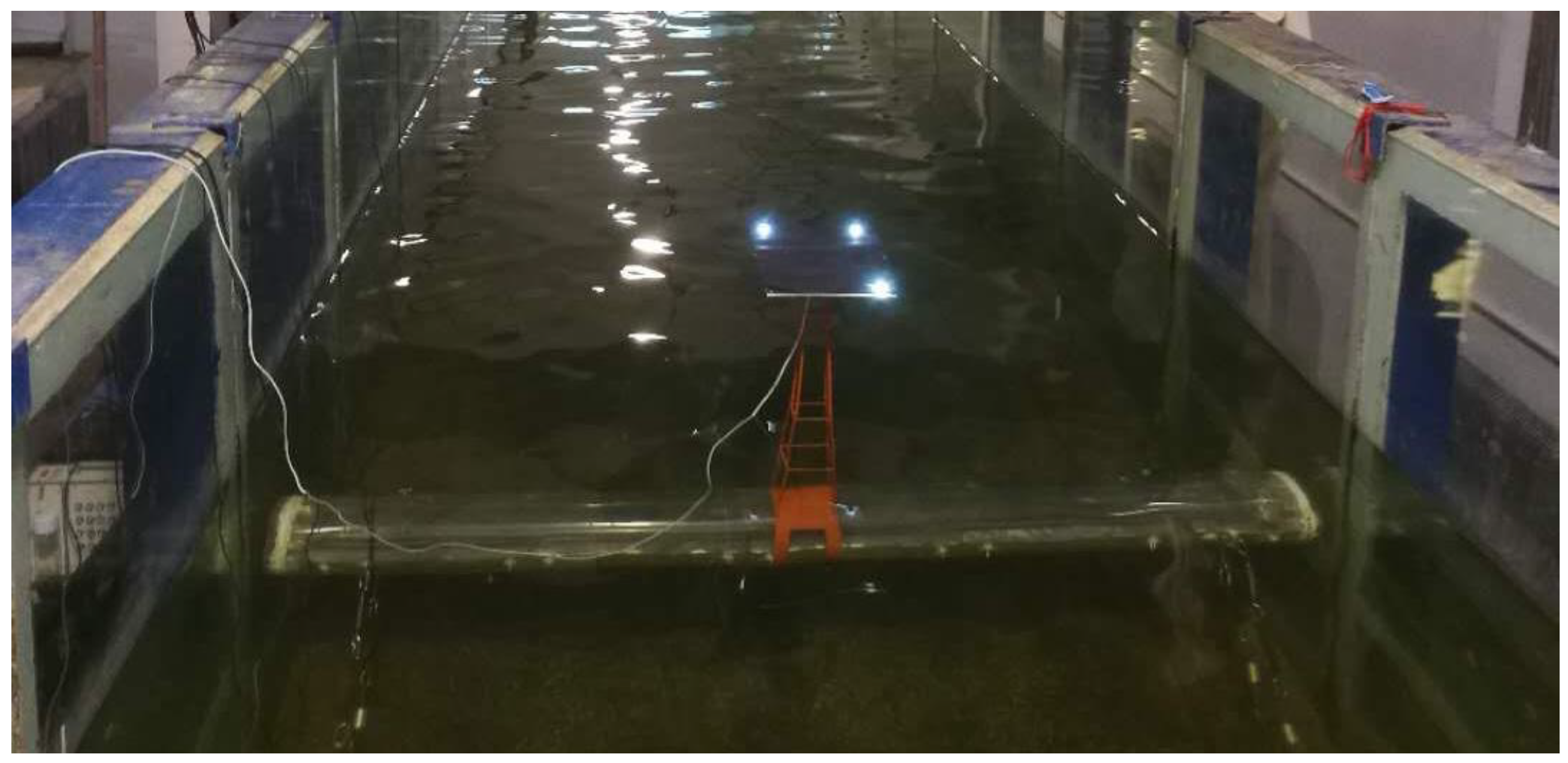
where Tm is the mooring tension of the model cable (N), Cp is the elasticity coefficient of the prototype cable (for steel cable Cp = 26.97 × 10⁴ MPa), dp is the diameter of the prototype cable (m), ΔS/S is the relative elongation of cable, and n is the index with steel cable adopting n = 1.5. The simulation of mooring lines matches both elastic and gravity similarity. An example of a theoretical tension deformation curve and measured scatters are presented in Figure 1. It shows that excellent agreement was achieved. Figure 2 shows the layout and mooring pattern of the model in wave flume, 1#~4# indicate the number of the cable. and Figure 3 shows the moored SFT in wave tank. Four cables at one end of the tunnel section (the other end was the same) were parallel to each other in an inclined configuration (both inclined angles were 45°). The system is in equilibrium when the initial tension of each cable is F0 = 13 N.
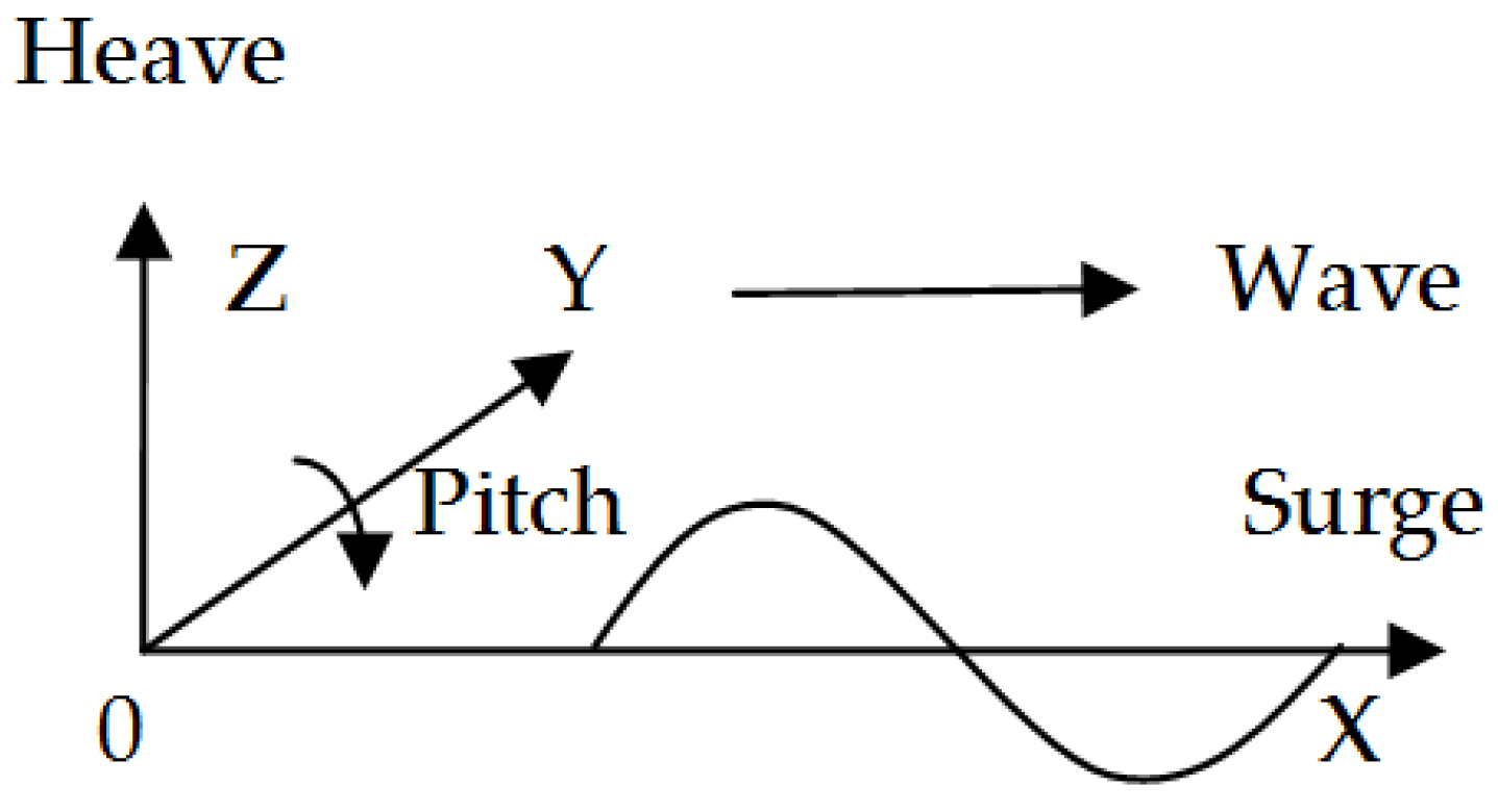
The two-dimensional SFT model was arranged 24 m from the wave maker, where the freak wave occurred. The coordinate system is shown in Figure 4. The origin of the coordinate system is defined at the centre of the model. Positive x is along the wave propagation, positive z is vertical up along the water depth, and positive y is determined by the right-hand rule. For the two-dimensional case, three motion components are investigated: surge, heave and pitch. Surge is the longitudinal motion along the x-axis (wave propagation direction is +); heave is the vertical motion along the z-axis (vertical up is +); and pitch is rotation around the y-axis (clockwise direction is +).

2.3. Experimental Parameters and Methods

2.3.1. Experimental Parameters

The experiments were divided into four sections: tests for the natural frequency of motion components (free decay tests in still water), tests for the response amplitude operators (RAO test) of motion and mooring tension (regular waves), and tests for the time history of the motion and mooring tension (freak and random waves).
The water depth was fixed at d = 1.2 m, the submerged depth was d0 = 42 cm (d0/d = 0.35, d0/D = 2.1) and the initial mooring tension was F0 = 13 N. The average wave height was set to H = 4.0 cm. The average period range T = 0.8~2.0 s, and the period interval for each test was 0.2 s. The experimental parameters are summarised in Table 2.
To investigate the effect of the freak wave parameter α1 (α1 = Hmax/Hs [22], ranges from 1.90 to 2.59) on the dynamic responses of the SFT, where Hmax and Hs represent the maximum wave height and significant wave height, respectively, the relative wave height and relative period were fixed (Hs/d0 = 0.095, TP/T0S = 1.25, TP/T0H = 1.23, TP/T0P = 2.96, where TP represent the spectral peak period, T0S, T0H and T0P are the natural frequencies of surge, heave and pitch, respectively). The experimental parameters are summarised in Table 3.

2.3.2. Experimental Method

In the present study, the freak wave was generated at the target location using a random wave train combined with two transient wave trains, which was proposed and used by Pei et al. [23]. With the linear superposition method, the wave surface can be expressed as Equation (2), where, η denotes the elevation of the water surface above the mean water level; A1i is amplitude of the random wave; A2i and A3i are amplitudes of the transient waves; tc and xc represent the time and space location of freak wave generation; ki is the wave number of the component wave, ωi is the circular frequency of the component wave, and εi is the random phase of the component wave, which is evenly distributed between 0 and 2π. To compare the experimental results measured under freak and random waves, the same spectrum with identical spectral parameters were applied. As to the wave surface, the statistical parameters such as H1/10, TH1/10, average period and average wave height are almost the same, except for the significant wave height HS, spectral peak period TP and wave spectrum. The measurement for each test typically lasted for more than 200 waves, and was performed 2 or 3 times to ensure the repeatability.
η x , t = η 1 x , t + η 2 x , t + η 3 x , t = i = 1 M A 1 i cos k i x + ω i t + ε i + i = 1 M A 2 i cos k i x x c + ω i t t c + i = 1 M A 3 i cos k i x x c + ω i t t c
In the experiments, P-M spectrum was applied as:
S ω = A ω 5 e x p B ω 4
A = 173 H s 2 T 0.1 4
B = 691 T 0.1 4
where Hs and T0.1 are the significant wave height and the average period calculated from the spectral moment, respectively.
The model was installed and moored with an initial tension of 13 N, where the freak wave occurred. The measurement for each test typically lasted for more than 200 waves, and was performed 2 or 3 times to ensure the repeatability.

3. Results and Discussion

3.1. Free Decay Test and RAO Test

3.1.1. Free Decay Test

The free decay test for two-dimensional SFT was performed in still water and the time histories of the surge, heave and pitch were measured. The natural periods and equivalent damping of the surge, heave and pitch are analysed and summarised in Table 4. The natural period of the pitch was significantly shorter than those of the surge and heave, indicating that the mooring system had a strong constraint effect on the pitch.

3.1.2. RAO Test

The RAO test was performed using the experimental parameters listed in Table 2. Figure 5 shows the RAO test results. The abscissas of the RAO curves for surge, heave and pitch were dimensionless with their respective natural periods, the abscissas of the RAO curves for mooring tension were dimensionless with the natural period of surge, and the ordinate represents the dynamic response values under unit height wave.
As shown in Figure 5, the maximum surge and heave of the 2D SFT appeared near their respective natural periods, and the RAO variations of the three motion components were similar. Within the range of the wave period tested in the experiment, the maximum pitch appeared near the wave period, which was twice the natural pitch period (T/T0P = 2.0). The maximum pitch occurred almost synchronously with the maximum surge and heave, indicating a significant coupling effect between the natural periods of each degree of freedom. Simultaneously, the RAO variations in the mooring tension were nearly identical to those of the surge, with the maximum mooring tension appearing near T/T0S = 1.0.

3.2. Dynamic Response Characteristics in Time Domain

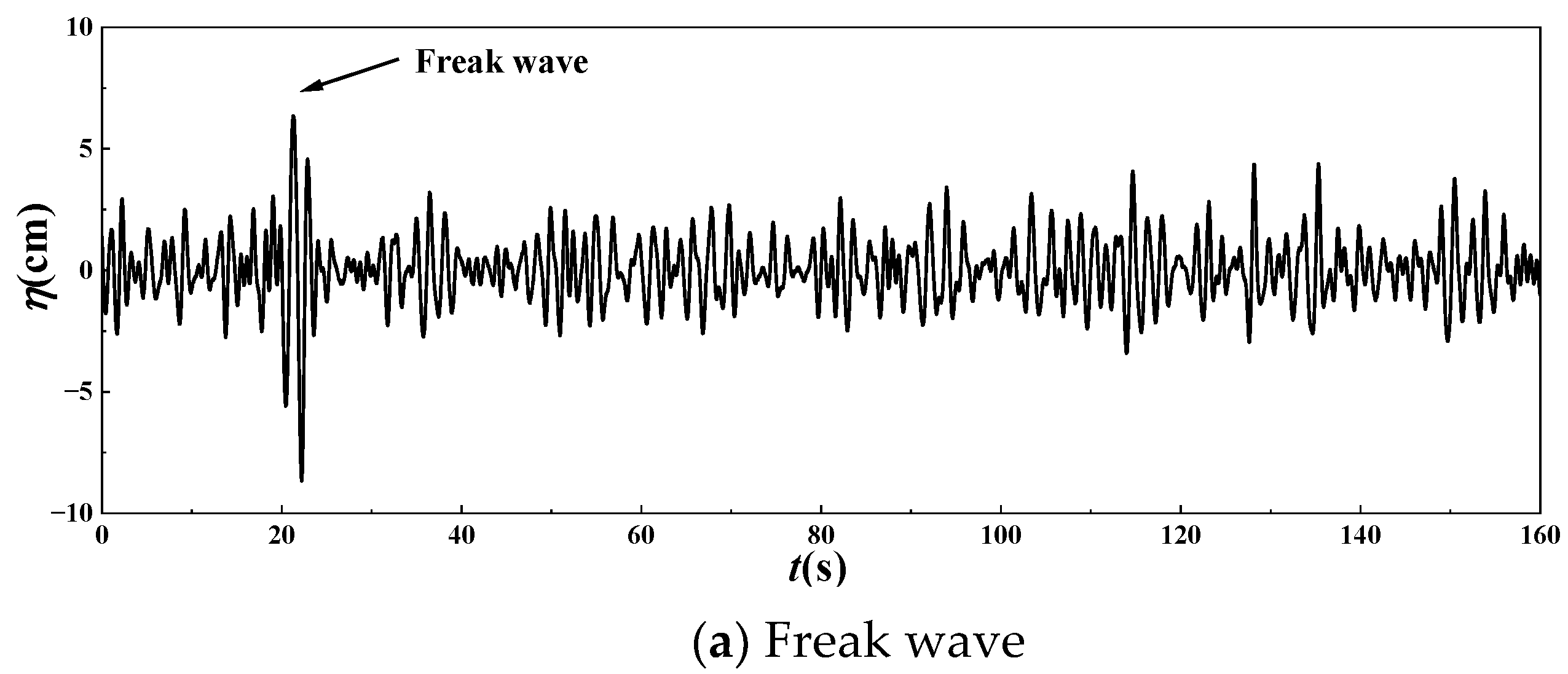
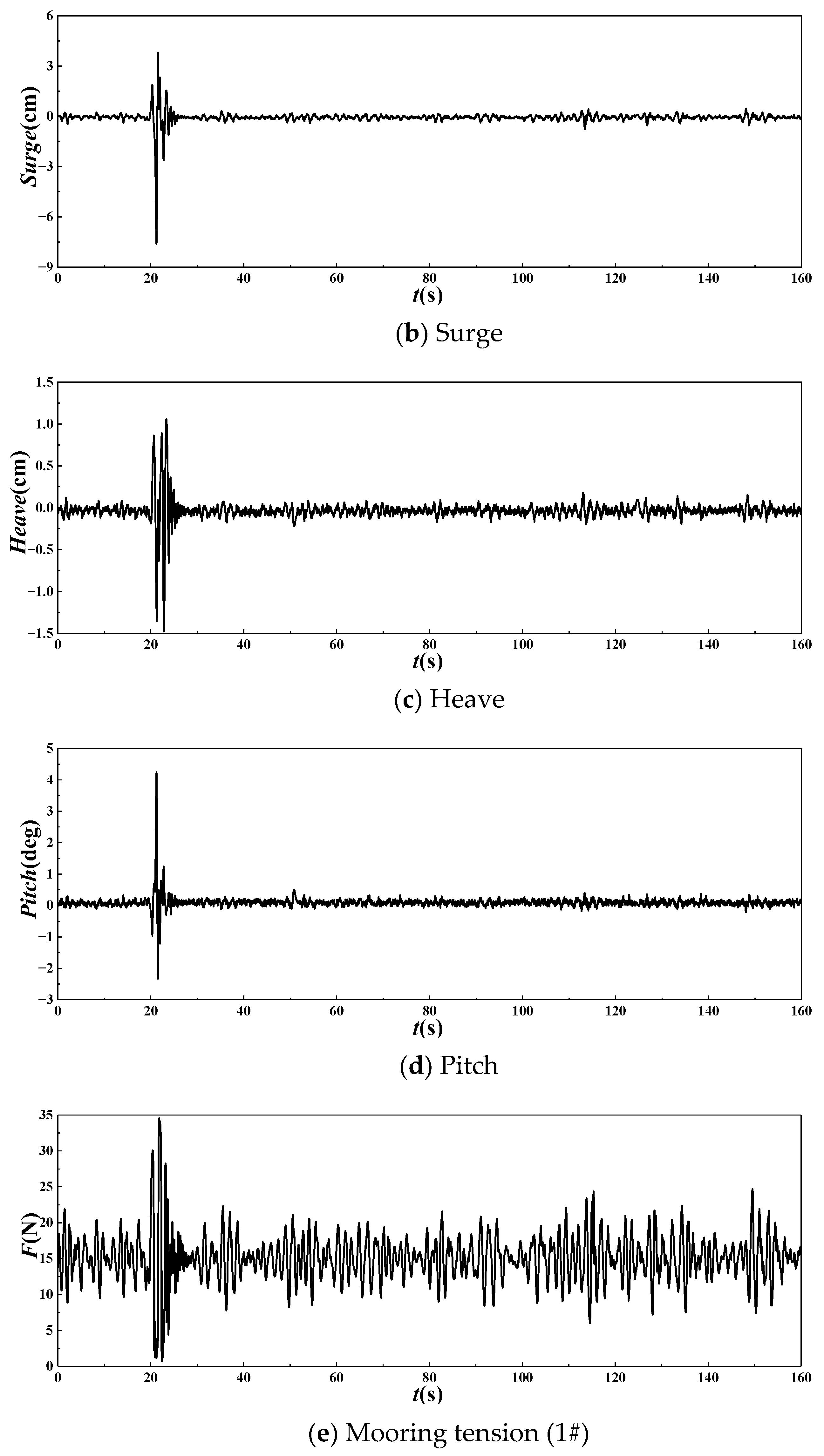
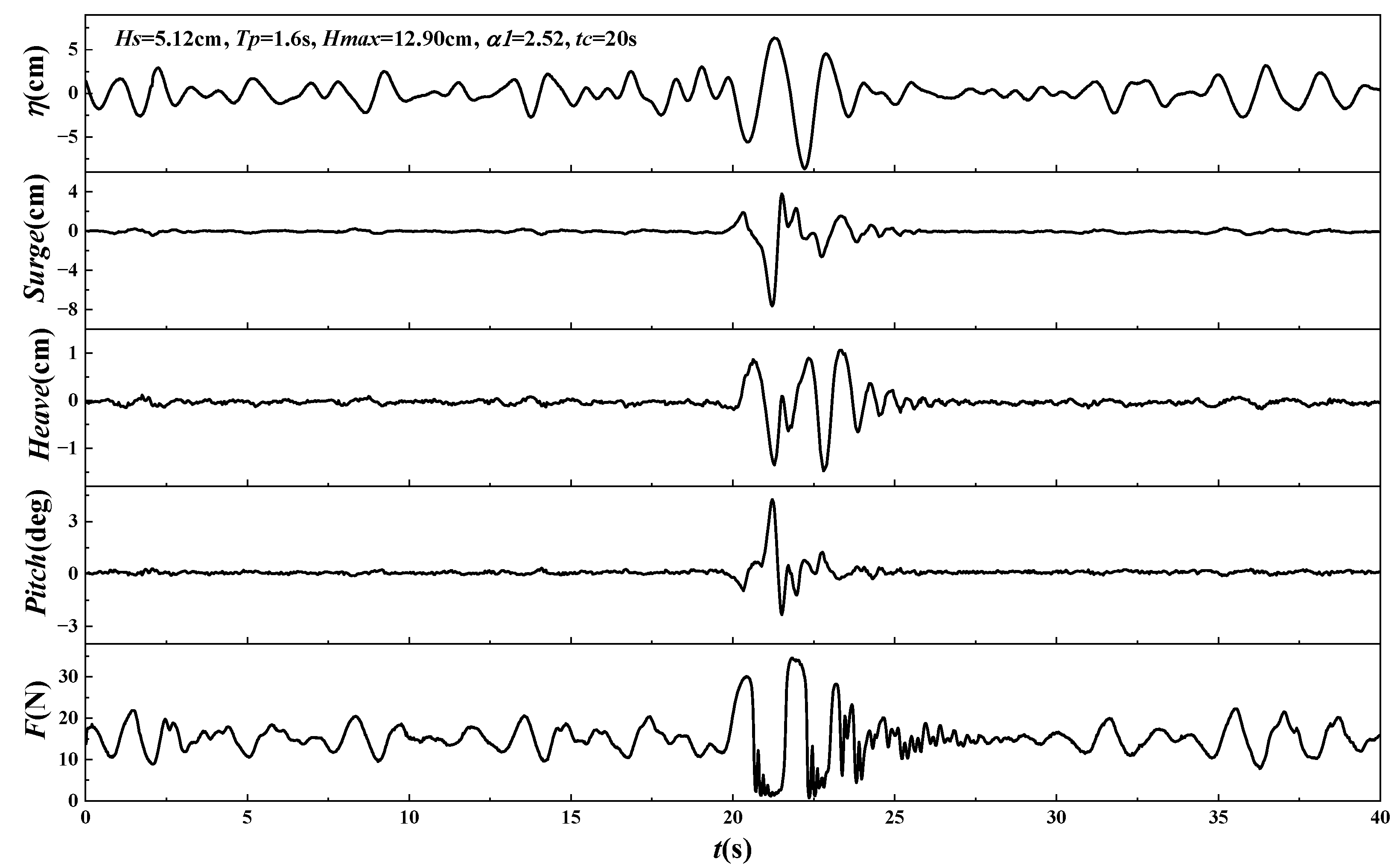
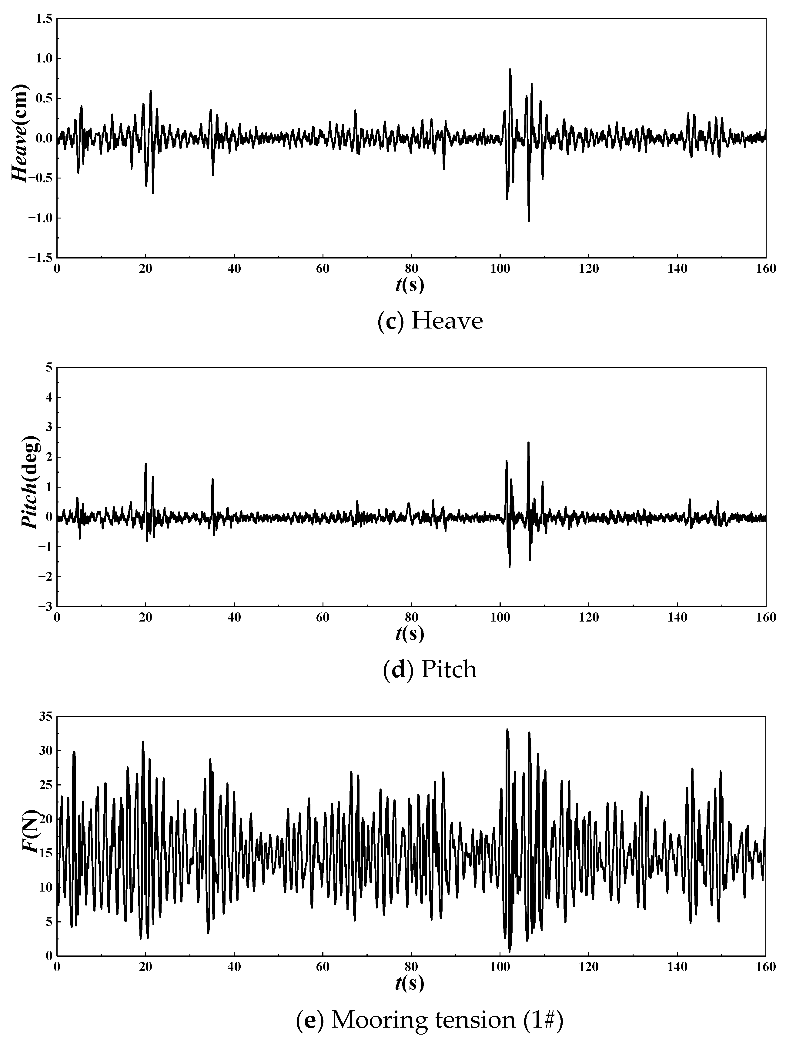
Figure 6 shows an example of the time histories of the freak wave surface and the dynamic responses of the 2D SFT under freak waves. Figure 7 presents the magnified details. In this example, the freak wave has the following characteristics: significant wave height Hs = 5.0 cm, maximum wave height Hm = 12.9 cm, peak period TP = 1.6 s, freak parameters α1, α2, α3 and α4 = 2.52, 1.94, 2.19 and 0.65, respectively. Moreover, the relative submergence depth is d0/LP ≈ 0.11, d0/d = 0.35, d0/Hs = 8.2 and d0/Hm = 3.3.
Figure 5 and Figure 7 show that under the above experimental conditions, motion responses of the SFT were considerably small under the wave train in the remaining periods, except for the period of freak wave occurrence. This is because the freak wave has a greater height than the other waves in the wave train and the freak wave may have an amplification effect. Meanwhile, the freak wave has strong nonlinearity and the wave energy rapidly accumulates with the occurrence of the freak wave, where the energy density is the largest; therefore, a large impact force is generated on the structure, which makes the vibration frequency of the floater close to the natural frequency, thus generating a high frequency resonance response and being characterized by strong-nonlinearity.
The difference between the mooring tension under freak wave and waves in the remaining times was significantly smaller than that corresponding to motions. This could be because the initial tension of the cable was large and the mooring tension was considerably sensitive to the motion response of the tunnel.
The surge, heave and pitch exhibited significant extreme values (consistent with the occurrence of the freak wave) under the freak wave. The maximum surge was opposite to the direction of wave propagation, which can be attributed to the abnormally large trough of the freak wave.
After the freak wave acts on the system, the motion and mooring tension of the SFT oscillate at a high frequency. The variation in the mooring tension on the upstream side corresponded to the variation in the wave surface, except during the freak wave occurrence. This is different from the dynamic characteristics of the mooring square column induced by the freak wave investigated by Pan et al. [16,17,18]. The surge and mooring tension exhibited significant extreme values (consistent with the occurrence of the freak wave) under the freak wave, followed by a long-term, significant, low-frequency oscillation. This low-frequency oscillation, which could last up to 30 s (approximately 20TP), was significantly larger than the low-frequency oscillation caused by other waves outside the occurrence period of the freak wave. The difference between the dynamic response characteristics of the mooring rectangular cylinder and the SFT under the freak wave is mainly due to the difference in the stiffness and initial tension of the cable. The rectangular cylinder was moored with a soft mooring configuration and an initial tension of F0 = 1.1 N, while the SFT was moored with a tight mooring configuration and an initial tension of F0 = 13 N.
Special attention should be paid to the fact that the dynamic responses of the SFT, particularly the motion response components induced by the freak wave, are significantly greater than those induced by the maximum wave in the wave train (excluding freak waves). The maximum motion response caused by freak waves can be several times larger than those caused by other large waves in the wave train (excluding freak waves), exceeding the proportion of the corresponding wave height. This demonstrates the amplification effect of the freak wave on the motion response of the submerged floating tunnel.
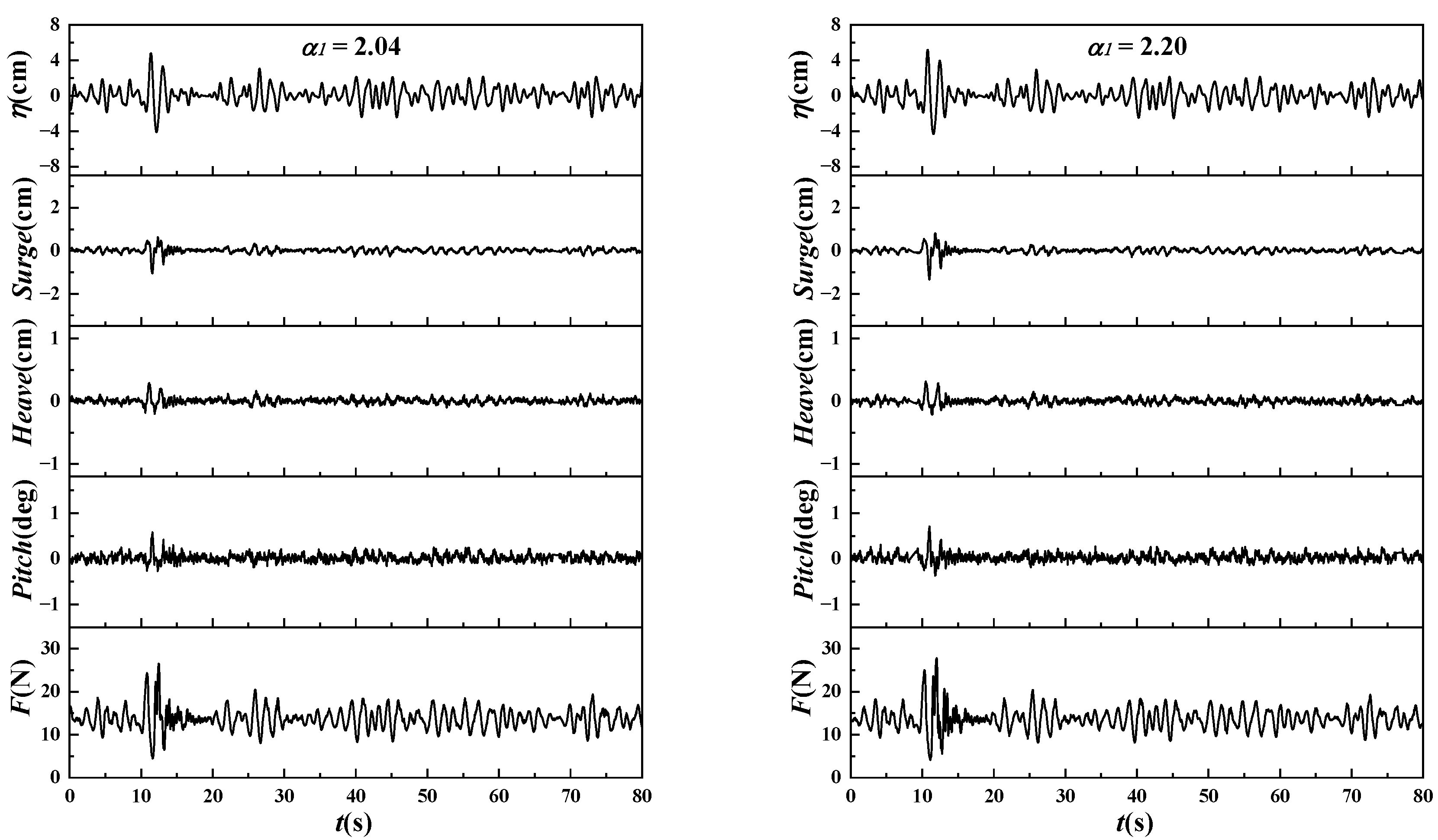
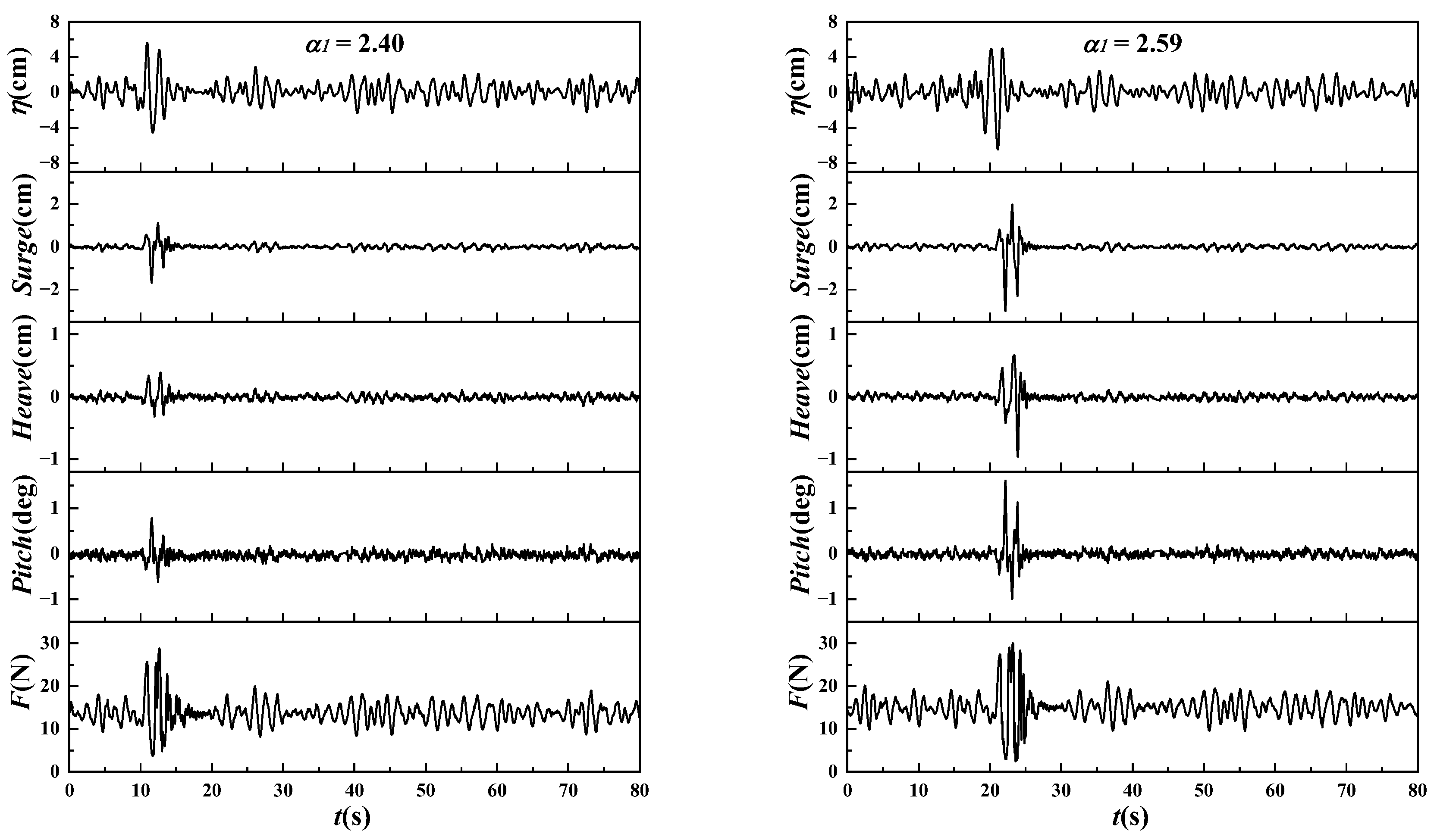
Figure 8 shows measured time histories of the dynamic responses of the SFT induced by four freak waves with different freak wave parameters α1 (identical wave spectrum). The α1 of the four freak waves were 2.04, 2.20, 2.40 and 2.59, respectively. The other experimental parameters included a significant wave height Hs = 4.0 cm, peak period TP = 1.6 s, relative submerged depth d0/LP = 0.11 and d0/Hs = 10.5.
Based on Figure 8 in the four cases, the dynamic responses of the system were quite small in all time periods, except for the period of the freak wave occurrence. Table 5 compared the maximum dynamic responses induced by the freak wave and those induced by the maximum waves (excluding the freak wave) in the same wave train. The motion response under the freak wave is much larger than those induced by the maximum wave (excluding the freak wave) in the same wave train, indicating that the freak wave has an amplification effect on the motions, which increases as the α1 increases.
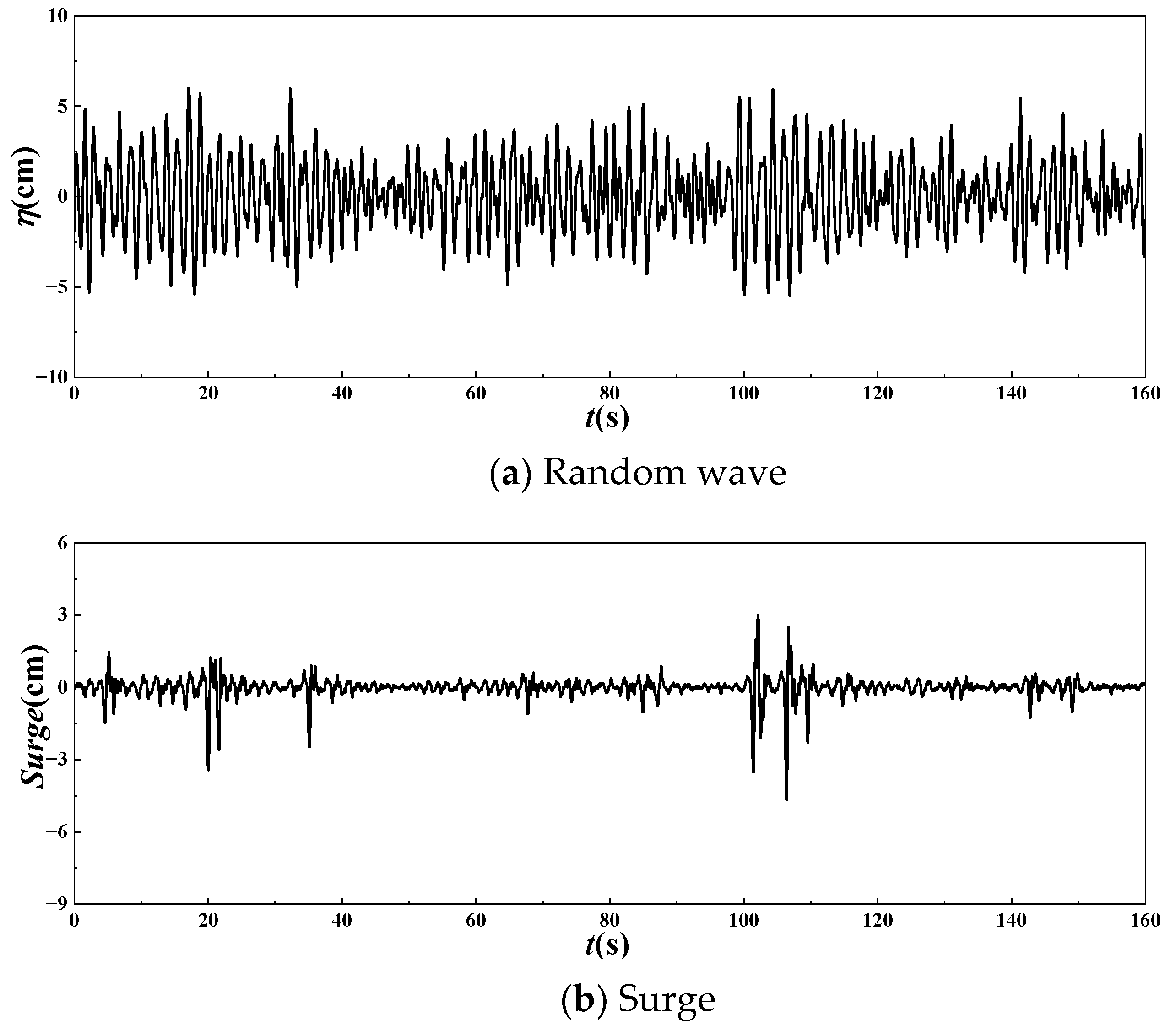
Two sets of wave trains with the same peak period (TP = 1.6 s) and different significant wave heights were selected to show the dynamic amplification of the freak wave on the dynamic responses of the SFT. One was a random wave train that had a freak wave with a significant wave height of Hs = 5.0 cm and a maximum wave height of Hm = 12.6 cm, while the other was a random wave train that had a significant wave height of Hs = 8.0 cm and a maximum wave height of Hm = 11.4 cm. Figure 6 and Figure 9 show the time histories of the two wave elevations and corresponding dynamic responses of the SFT, respectively. The maximum surge, heave and pitch of the SFT under the freak wave were 1.42, 1.19 and 1.49 times than those under the random wave, even though the significant wave height of the random wave was 1.6 times than that of the freak wave.

3.3. Time Domain Amplification Effect of Freak Waves on Dynamic Response

3.3.1. Statistical Characteristics of Dynamic Responses under Different α1

The freak wave parameter α1 was varied in the range of 1.90~2.59 and other parameters were fixed: water depth d = 120 cm, initial tension F0 = 13 N, submerged depth d0 = 42 cm, relative draft depth d0/d = 0.35, spectral peak period TP = 1.6 s (relative periods TP/T0S = 1.25, TP/T0H = 1.23, and TP/T0P = 2.96) and significant wave height Hs = 4.0 cm (relative wave height Hs/d0 = 0.1).
(1) Comparison of statistical characteristics of motion responses
Figure 10 shows the statistical characteristic values of the surge, heave and pitch of the 2D SFT induced by the freak wave versus the freak wave parameter α1. In Figure 10, Smax, S1/10, S1/3 and Saverage represent the maximum, 1/10 maximum, 1/3 maximum and average values of the dimensionless surge, respectively. The heave and pitch expressions are similar. Subscripts ‘max’ and ‘min’ represent the maximum positive and negative values, respectively.
Figure 10 shows that with α1 varying between 1.90~2.59, the surge, heave and pitch of the SFT are all significantly correlated with α1. The positive and negative maximum values of each motion component increase nonlinearly as α1 increases. The 1/10 maximum, 1/3 maximum and average values of the motions induced by the freak wave are significantly smaller than the maximum value and remain unchanged with the increase of α1. In other words, statistically, the influence of the freak wave on motion response is limited to the maximum value.
(2) Comparison of statistical characteristics of mooring tensions
Figure 11 shows the statistical characteristic values of the upstream and downstream mooring tensions induced by the freak wave versus α1. In Figure 11, Fmax, F1/10, F1/3 and Faverage represent the maximum, 1/10 maximum, 1/3 maximum and average values of the dimensionless tension, respectively.
Figure 11 shows that the variation in upstream and downstream mooring tensions induced by the freak wave is consistent with the α1. The maximum mooring tensions increase as α1 increases, whereas the 1/10 maximum, 1/3 maximum and average values are significantly smaller than the maximum values and remain unchanged with the increase of α1. These results are consistent with the influence of the freak wave on the motion response of SFT.

3.3.2. Dynamic Response Amplification Coefficient in Time Domain

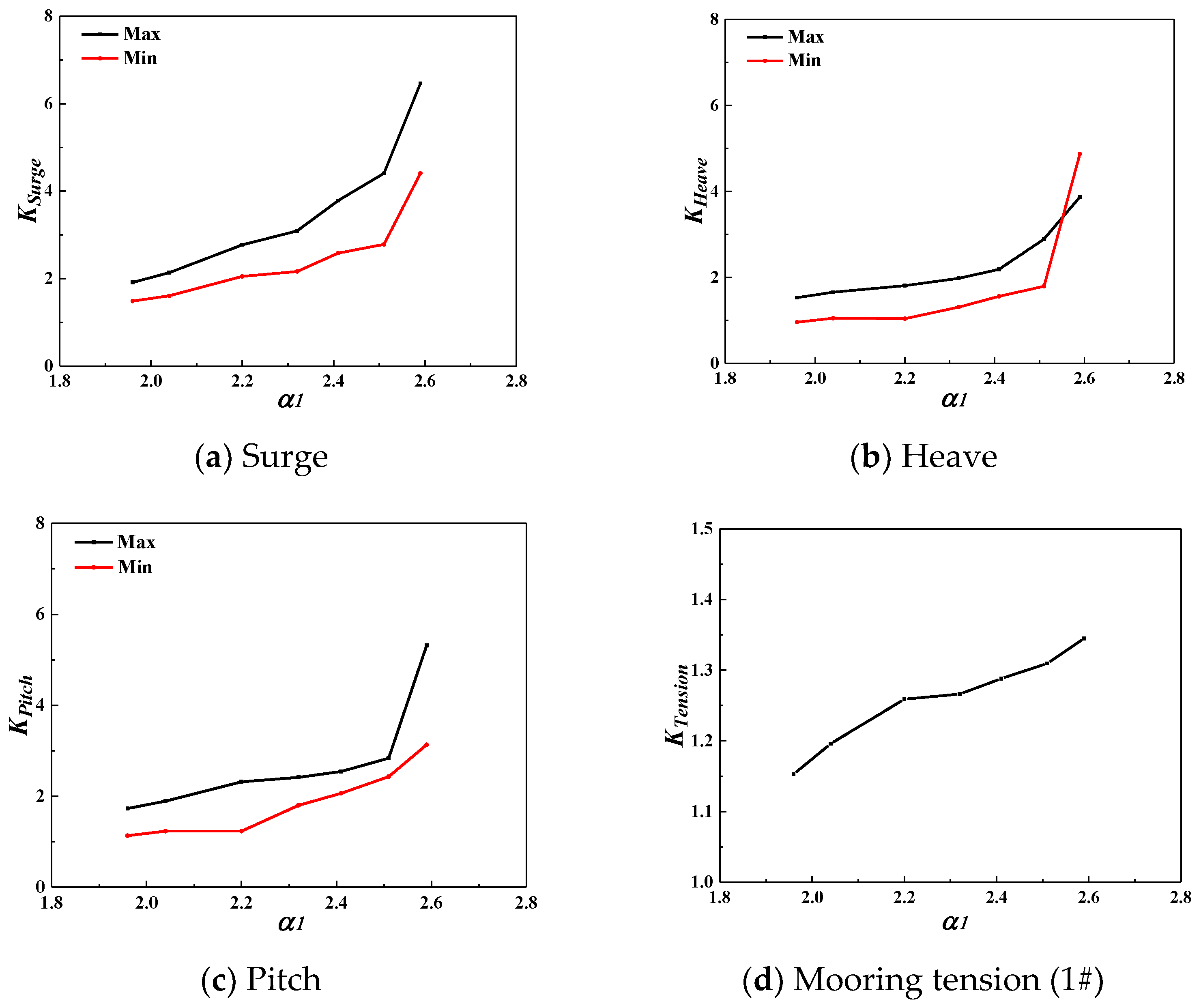
According to the previous analysis, the maximum values of the surge, heave, pitch and mooring tension of the SFT under the freak wave were significantly larger than those under the random wave with an identical spectrum. This phenomenon is known as the “dynamic amplification effect of freak wave”, which is referred to here as the “amplification effect”. The ratio of the maximum motion response under freak and random waves with identical spectrums is defined as the “amplification coefficient of the motion response” to quantitatively describe the amplification effect of the freak wave on the dynamic responses. The surge amplification coefficient is KSurge = Sfmax/Simax, the heave amplification coefficient is KHeave = Hfmax/Himax and the pitch amplification coefficient is KPitch = Pfmax/Pimax. The ratio of the maximum mooring tension under freak and random waves is defined as the “amplification coefficient of the mooring tension”, which is expressed as KTension = Tfmax/Timax.
Sfmax, Hfmax, Pfmax and Simax, Himax, Pimax represent the maximum surge, heave, pitch under freak and random waves, respectively. Tfmax and Timax represent the maximum mooring tension under freak and random waves, respectively. To compare the experimental results measured under freak waves and random waves, the same spectrum with identical spectral parameters was applied. As to the wave surface, besides the significant wave height HS and the spectral peak period TP, the statistical parameters such as H1/10, TH1/10, average period and average wave height are almost the same.
(1) Variation of amplification coefficient with α1
Figure 12 shows the variation of the amplification coefficients of surge, heave, pitch and mooring tension of the 2D SFT with the freak wave parameter α1. Max and Min in the Figure represent the ratio of the maximum values of dynamic response (motion response and mooring tension) in the positive and negative directions caused by freak waves and random waves. The freak wave parameter α1 has a considerable impact on the amplification coefficients of the surge, heave and pitch, which all increase nonlinearly as the α1 increases. When the α1 varies in the range of 1.90~2.59, the variation trend for amplification coefficients of the motions in the positive and negative directions is the same, but the magnitudes are different, which may be because of differences between the peaks and the troughs of freak waves. The amplification coefficients of surge, heave and pitch in the positive direction vary in the range of 1.91~6.46, 1.53~3.87 and 1.73~5.32, respectively, and 1.49~4.41, 0.97~4.87 and 1.13~3.13 in the negative direction. As α1 increases, the amplification coefficients of mooring tension in the upstream cable increase almost linearly in the range of 1.15~1.35. The amplification effect of the freak wave on the mooring tension is much smaller than that on the motion responses.
(2) Variation of generalised amplification coefficient with α1
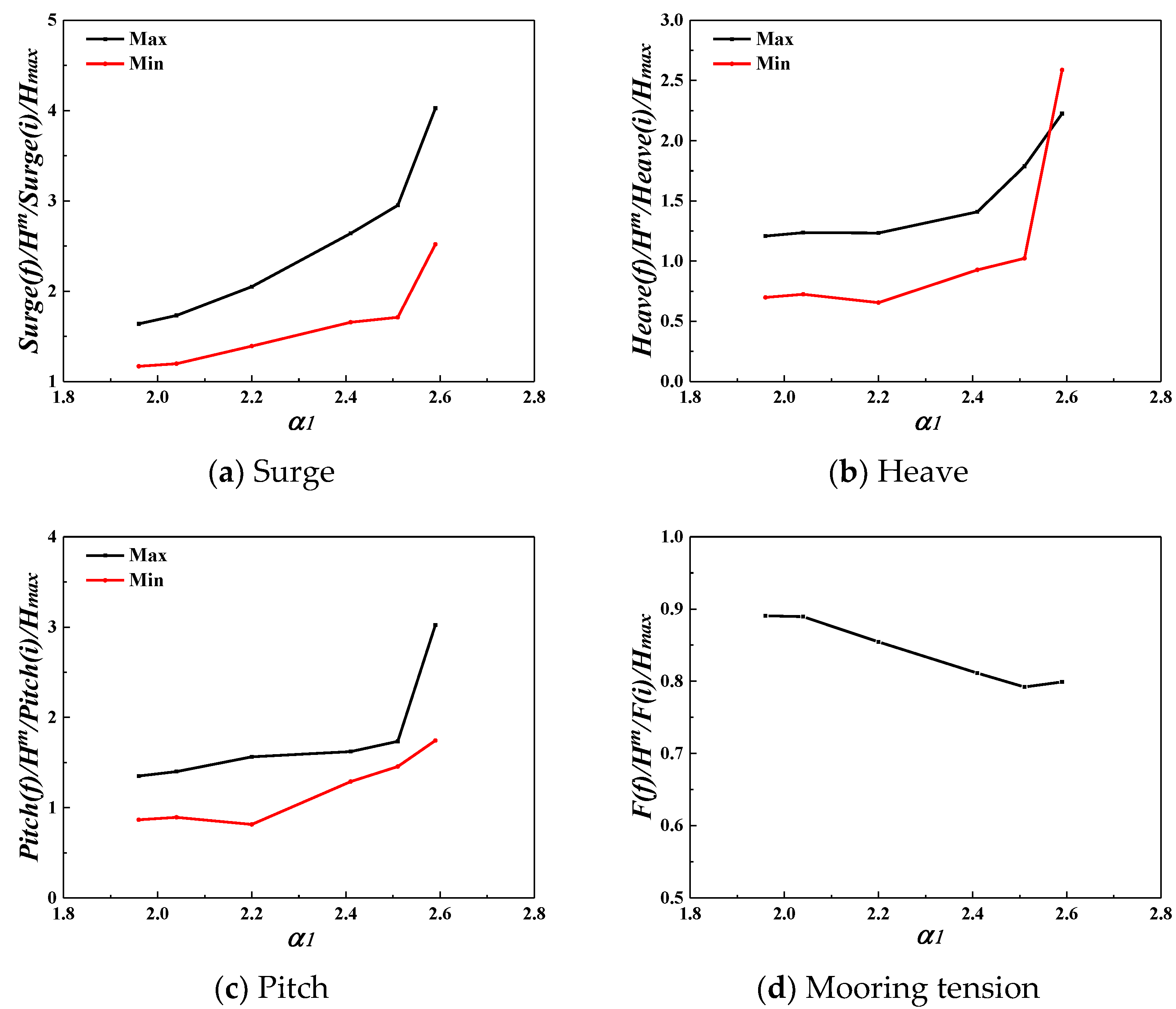
According to the results of the preceding analysis, the amplification effect of the freak wave on the dynamic responses of the SFT is significantly related to the height of the freak wave. Therefore, the generalised dynamic amplification coefficient is defined as the ratio of the maximum values of dynamic response (motion response and mooring tension) in the positive and negative directions caused by freak waves and random waves, which are divided by the maximum wave height in the wave train, such as the generalised dynamic amplification coefficient of the surge: [Surge(f)/Hm]/[Surge(i)/Hmax]. Figure 13 shows the variation of the generalised dynamic amplification coefficients versus α1. In fact, under the condition of constant Hs, an increase in α1 implies increasing maximum wave height. The increase in dynamic response exceeded the linear growth of the maximum wave height when the generalised amplification coefficient of the dynamic response exceeded 1.0. Conversely, it was lower than the linear growth rate of the maximum wave height.
Figure 13 shows that the generalised amplification coefficients of motion responses increase as α1 increases and are all larger than 1.0, indicating that the growth rates of motion responses of SFT under the freak wave exceed the linear growth rate of the maximum wave height, and the motions exhibit a significant nonlinear increase as the maximum wave height increases. The generalised amplification coefficient of the mooring tension decreases as α1 increases and is less than 1.0. This demonstrates that the dynamic amplification effect of the freak wave on the mooring tension is much smaller than the amplification effect on motion responses. The growth rate of the mooring tension under the freak wave was less than the linear growth rate of the freak wave height.

4. Conclusions

The dynamic response characteristics of a two-dimensional submerged floating tunnel (SFT) under freak and random waves were investigated in the present study. The dynamic amplification effect of the freak wave was analyzed and the “amplification coefficient of the dynamic response” was proposed. Based on the analysis of the experimental results, the following main conclusions were obtained.
(1) The freak wave has strong nonlinearity, and the wave energy rapidly accumulates with the occurrence of the freak wave; therefore, a large impact force is generated on the structure, which may make the vibration frequency of the SFT close to the natural frequency, and which generates a high frequency resonance response and strong nonlinear characteristics;
(2) The dynamic responses of the SFT under the freak wave are significantly larger than those under the largest wave in the wave train excluding the freak wave, particularly the motion response. The maximum values of the motion responses induced by the freak wave were several times larger than those induced by the largest wave in the wave train excluding the freak wave, far exceeding the proportion of corresponding wave height. This shows the amplification effect of the freak wave on motion responses of the SFT, and the effect increases as the freak wave parameter α1 increases;
(3) With the freak wave parameter α1 varying in the range of 1.90~2.59, the surge, heave and pitch of the SFT are significantly correlated with the α1. The positive and negative maximum values of each motion response component increase nonlinearly as α1 increases;
(4) The freak wave parameter α1 has a considerable impact on the amplification coefficients of the surge, heave and pitch, which all increase nonlinearly as the α1 increases. When the α1 varies in the range of 1.90~2.59, the amplification coefficients of surge, heave and pitch in the positive direction vary in the range of 1.91~6.46, 1.53~3.87 and 1.73~5.32, and 1.49~4.41, 0.97~4.87, and 1.13~3.13 in the negative direction. As α1 increases, the amplification coefficients of mooring tension in the upstream cable increase almost linearly in the range of 1.15~1.35. The amplification effect of the freak wave on the mooring tension is much smaller than that on the motion responses;
(5) The generalised amplification coefficients of motion responses increase as α1 increases and are all larger than 1.0, indicating that the growth rates of motion responses under the freak wave exceed the linear growth rate of the maximum wave height. The generalised amplification coefficient of the mooring tension decreases as α1 increases and is less than 1.0. This demonstrates that the dynamic amplification effect of the freak wave on the mooring tension is much smaller than the amplification effect on motion responses. The growth rate of the mooring tension under the freak wave was less than the linear growth rate of the freak wave height.

Author Contributions

Validation, analysis, investigation, writing—original draft preparation and editing, W.P.; visualization, analysis, writing—original draft preparation and editing, M.H.; conceptualization, methodology, and writing—review and editing, C.C. All authors have read and agreed to the published version of the manuscript.

Funding

This research was funded by the National Natural Science Foundation of China (51509120).

Institutional Review Board Statement

Not applicable.

Informed Consent Statement

Not applicable.

Data Availability Statement

The data presented in this study are available on request from the corresponding author upon reasonable request.

Conflicts of Interest

The authors declare no conflict of interest.

References

  1. Kharif, C.; Pelinovsky, E. Physical mechanisms of the rogue wave phenomenon. Eur. J. Mech. B Fluids 2003, 22, 603–634. [Google Scholar] [CrossRef]
  2. Kimura, A.; Ohta, T. Probability of the freak wave appearance in a 3-dimensional sea condition. In Proceedings of the 24th International Conference on Coastal Engineering. Part 1 (of 3), Kobe, Japan; ASCE: New York, NY, USA; Kobe, Japan, 1995; pp. 356–369, ISBN 08938717. [Google Scholar]
  3. Fochesato, C.; Grilli, S.; Dias, F. Numerical modeling of extreme rogue waves generated by directional energy focusing. Wave Mot. 2007, 44, 395–416. [Google Scholar] [CrossRef]
  4. Pelinovsky, E.; Talipova, T.; Kharif, C. Nonlinear-dispersive mechanism of the freak wave formation in shallow water. Phys. D Nonlinear Phenom. 2000, 147, 83–94. [Google Scholar] [CrossRef]
  5. Cui, C.; Pan, W.-B. Experimental Study on the Wavelengths of Two-Dimensional and Three-Dimensional Freak Waves. China Ocean Eng. 2023, 37, 154–164. [Google Scholar] [CrossRef]
  6. Gibson, R.S.; Swan, C. The evolution of large ocean waves: The role of local and rapid spectral changes. Proc. R. Soc. A Math. Phys. Eng. Sci. 2007, 463, 21–48. [Google Scholar] [CrossRef]
  7. Akhmediev, N.; Ankiewicz, A.; Soto-Crespo, J.M.; Dudley, J.M. Rogue wave early warning through spectral measurements? Phys. Lett. Sect. A Gen. At. Solid State Phys. 2011, 375, 541–544. [Google Scholar] [CrossRef]
  8. Rudman, M.; Leontini, J.; Cleary, P.; Sinnott, M.; Prakash, M. Rogue wave impact on a semi-submersible offshore platform. In Proceedings of the 27th International Conference on Offshore Mechanics and Arctic Engineering, OMAE 2008, Estoril, Portugal, 15–20 June 2008; OMAE: Estoril, Portugal, 2008; pp. 887–894, ISBN 9780791848227. [Google Scholar]
  9. Paul, P.W.; Rudman, M. Extreme wave interaction with a floating oil rig: Prediction using SPH. Prog. Comput. Fluid Dyn. 2009, 9, 332–344. [Google Scholar]
  10. Rudman, M.; Cleary, P.W. Rogue wave impact on a tension leg platform: The effect of wave incidence angle and mooring linetension. Ocean Eng. 2013, 61, 123–138. [Google Scholar] [CrossRef]
  11. Gu, J.Y.; Lv, H.N.; Yang, J.M. Dynamic response study of four column TLP in freak waves. Ocean. Eng. 2013, 31, 25–36. (In Chinese) [Google Scholar]
  12. Shen, Y.G.; Yang, J.M.; Li, X. Numerical investigation on the motion response of semisubmersible platform under extreme waves. Ocean. Eng. 2013, 31, 9–17. (In Chinese) [Google Scholar]
  13. Deng, Y.F.; Yang, J.M.; Xiao, L.F. Influence of wave group characteristics on the motion of a semisubmersible in freak waves. In Proceedings of the ASME 33rd International Conference on Ocean, Offshore and Arctic Engineering, San Francisco, CA, USA, 8–13 June 2014; pp. 56–64. [Google Scholar]
  14. Gao, N.; Yang, J.; Zhao, W.; Li, X. Numerical simulation of deterministic freak wave sequences and wave-structure interaction. Ships Offshore Struct. 2016, 11, 802–817. [Google Scholar] [CrossRef]
  15. Deng, Y.F.; Yang, J.M.; Xiao, L.F. An experimental investigation on the motion and dynamic responses of a semisubmersible in freak waves. In Proceedings of the 17th China Ocean (Coastal) Engineering Symposium, Nanning, China, 13–16 November 2015; pp. 741–749. [Google Scholar]
  16. Pan, W.; Zhang, N.; Huang, G.; Ma, X. Experimental study on motion responses of a moored rectangular cylinder under freak waves (I: Time-domain study). Ocean Eng. 2018, 153, 268–281. [Google Scholar] [CrossRef]
  17. Pan, W.; Liang, C.; Zhang, N.; Huang, G. Experimental study on hydrodynamic characteristics of a moored square cylinder under freak wave (II: Frequency-domain study). Ocean Eng. 2021, 219, 108452. [Google Scholar] [CrossRef]
  18. Pan, W.; Zhang, N.; Zeng, F.; Huang, G. Time-frequency domain characteristics on the dynamic response of a moored floater under a freak wave by wavelet analysis. Int. J. Offshore Polar Eng. 2021, 31, 160–168. [Google Scholar] [CrossRef]
  19. Yang, Z.; Li, J.; Xu, Y.; Ji, X.; Sun, Z.; Ouyang, Q.; Zhang, H. Experimental study on the wave-induced dynamic response and hydrodynamic characteristics of a submerged floating tunnel with elastically truncated boundary condition. Mar. Struct. 2023, 88, 103339. [Google Scholar] [CrossRef]
  20. Yang, Z.; Li, J.; Zhang, H.; Yuan, C.; Yang, H. Experimental study on 2D motion characteristics of submerged floating tunnel in waves. J. Mar. Sci. Eng. 2020, 8, 123. [Google Scholar] [CrossRef]
  21. Li, Q.; Jiang, S.; Chen, X. Experiment on Pressure Characteristics of Submerged Floating Tunnel with Different Section Types under Wave Condition. Pol. Marit. Res. 2018, 25, 54–60. [Google Scholar] [CrossRef]
  22. Klinting, P.; Sand, S. Analysis of prototype freak waves. In Coastal Hydrodynamic; ASCE: New York, NY, USA, 1987; pp. 618–632. [Google Scholar]
  23. Pei, Y.G. The Generation of Freak Waves and Its Behaviors; Dalian University of Technology: Dalian, China, 2008. [Google Scholar]
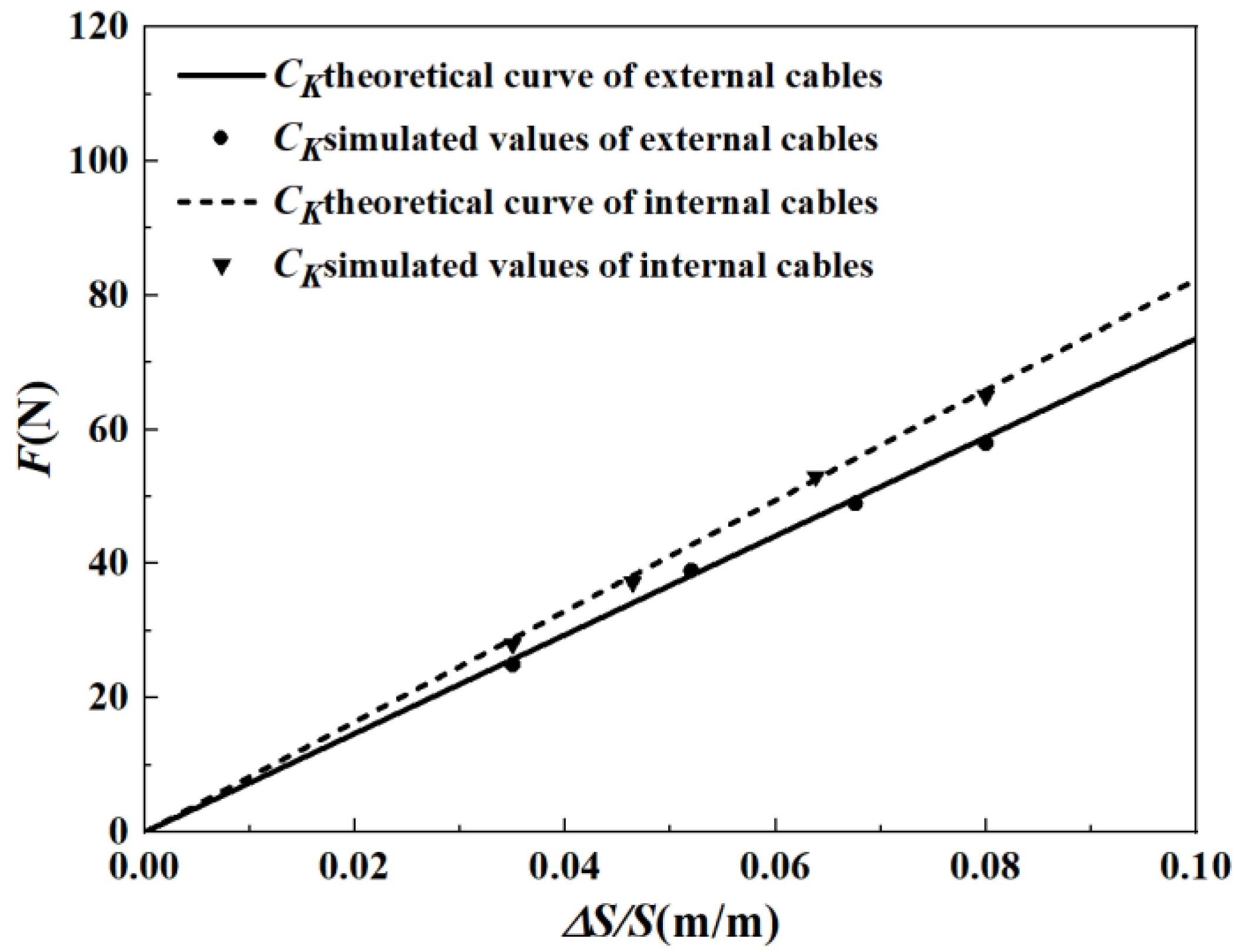
Figure 1. Tension-relative elongation curve of the cables.
Jmse 11 00977 g001
Figure 2. Mooring configuration of the SFT.
Jmse 11 00977 g002
Figure 3. The moored SFT in wave tank.
Jmse 11 00977 g003
Figure 4. The coordinate system.
Jmse 11 00977 g004
Figure 5. RAOs of the 2D SFT.
Jmse 11 00977 g005
Figure 6. Example of time-histories of the freak wave and dynamic responses of the SFT. (Hs = 5.0 cm, α1 = 2.52, d0/LP = 0.11, d0/d = 0.35, d0/Hs = 8.2 and d0/Hm = 3.3).
Jmse 11 00977 g006aJmse 11 00977 g006b
Figure 7. Zoomed-in details of the time-histories of the freak wave and dynamic responses of the SFT (Hs = 5.0 cm, α1 = 2.52, d0/LP = 0.11, d0/d = 0.35, d0/Hs = 8.2 and d0/Hm = 3.3).
Jmse 11 00977 g007
Figure 8. Time-histories of freak waves and dynamic responses of SFT with various α1 (Hs = 4.0 cm, TP = 1.6 s, Hs/d0 = 0.10, d0/LP = 0.11 and d0/Hs = 10.5).
Jmse 11 00977 g008aJmse 11 00977 g008b
Figure 9. Time-histories of the random wave and dynamic responses of the SFT (Hs = 8.0 cm, Hs/d0 = 0.2, TP = 1.6 s, d0/Lp = 0.11, d0/d = 0.35 and d0/Hs = 5.25).
Jmse 11 00977 g009aJmse 11 00977 g009b
Figure 10. Statistical characteristics of motion responses versus α1 under the freak wave (Hs = 4.0 cm, TP = 1.6 s, TP/T0S = 1.25, TP/T0H = 1.23, and TP/T0P = 2.96).
Jmse 11 00977 g010
Figure 11. Statistical characteristics of the mooring tension versus α1 under the freak wave (Hs = 4.0 cm, TP = 1.6 s, TP/T0S = 1.25, TP/T0H = 1.23 and TP/T0P = 2.96).
Jmse 11 00977 g011
Figure 12. Amplification coefficients of dynamic responses versus α1 (Hs = 4.0 cm, TP = 1.6 s, TP/T0S = 1.25, TP/T0H = 1.23, and TP/T0P = 2.96).
Jmse 11 00977 g012
Figure 13. Generalised amplification coefficients of dynamic responses versus α1 (Hs = 4.0 cm, TP = 1.6 s, TP/T0S = 1.25, TP/T0H = 1.23, and TP/T0P = 2.96).
Jmse 11 00977 g013
Table 1. Summary of geometric and hydrodynamic parameters of the SFT.
ParametersSymbolsPrototypeUnitModelUnit
LengthL120.0m200.0cm
DiameterD12.0m20.0cm
MassM11232t52.0kg
Centre of gravityB9.6m16.0cm
Centre of buoyancyb012.0m10.0cm
Natural surge periodT0S9.90s1.29s
Natural heave periodT0H10.10s1.31s
Natural pitch periodT0P4.18s0.55s
Buoyancy weight ratioBWR1.20-1.20-
Table 2. Experimental parameters simulated in the RAO tests.
Fixed ParametersH (cm)T (s)Wave Length
L (m)
Relative Submerged Depth
d0/L
d =120 cm
d0 = 42 cm
d0/d = 0.35
F0 = 13 N
4.00.80.990.360
1.01.560.231
1.22.240.161
1.43.020.119
1.63.840.094
1.84.670.077
2.05.490.066
Table 3. Experimental parameters simulated in the tests for dynamic responses of SFT.
Fixed ParametersHs (cm)TP (s)Relative Wave HeightRelative Wave PeriodRelative Submerged Depth d0/LPα1
Hs/dHs/d0TP/T0STP/T0HTP/T0P
d = 120 cm
d0 = 42 cm
d0/d = 0.35
F0 = 13 N
4.01.60.0330.0951.251.232.960.1091.90
2.04
2.20
2.41
2.51
2.59
Table 4. Natural periods and equivalent damping of the SFT.
Natural ParametersSurgeHeavePitch
Natural period (s)1.281.300.54
Equivalent damping0.110.090.22
Table 5. Dynamic responses induced by the freak and maximum waves (excluding the freak wave).
Hs (cm)Tp (s)α1Smax/Smax-1Hmax/Hmax-1Pmax/Pmax-1Fmax/Fmax-1
4.01.62.042.231.711.951.24
2.202.811.882.501.29
2.403.522.693.391.36
2.596.697.686.191.35
Disclaimer/Publisher’s Note: The statements, opinions and data contained in all publications are solely those of the individual author(s) and contributor(s) and not of MDPI and/or the editor(s). MDPI and/or the editor(s) disclaim responsibility for any injury to people or property resulting from any ideas, methods, instructions or products referred to in the content.