Article

Innovative Solution of Torsional Vibration Reduction by Application of Pneumatic Tuner in Shipping Piston Devices

Faculty of Mechanical Engineering, Technical University of Košice, Letná 9, 042 00 Košice, Slovakia
*
Author to whom correspondence should be addressed.
J. Mar. Sci. Eng. 2023, 11(2), 261; https://doi.org/10.3390/jmse11020261
Submission received: 16 December 2022 / Revised: 12 January 2023 / Accepted: 16 January 2023 / Published: 23 January 2023
(This article belongs to the Special Issue Marine and Mechanical Engineering in Paradigm)

Abstract

:
The industries of shipping, shipbuilding and port operations are among those in which mechanical drives with piston machines are widely used. The wide use of piston machines is the result of many years of experience and many years of development and modernization of piston machines. Usually, they operate as mechanical drives with constant operating speeds, with the exception of drives with combustion engines, which operate in a wider range of operating speeds. The limiting condition of innovation of mechanical drives with piston machines, resulting from the nature of the piston machine operation, is the torsional oscillation. The effort to decrease an energy demand of mechanical drives requires the application of non-traditional working modes, which can be considered as a deactivation of the cylinders of piston machine or an expansion of the working speed range. One of the possibilities of eliminating these limiting factors is an application of a pneumatic tuner in mechanical drives, which, in contrast to traditional solutions, has a wide range of torsional stiffness that can be smoothly changed. During experimental measurements in the resonance area, at the operating speed of 700 rpm after torsional stiffness change, a torsional vibration value of 15 Nm decreased to 5 Nm.

1. Introduction

Drive systems as well as shipping devices are the basic units of technological equipment for industry, production, ship transport and ship handling equipment, but also serve as equipment for supporting service activities in maritime transport. Assuming a determination of development trends, new propulsion systems will be diversified [1,2,3,4].
A significant share of consumed energy is attributed to drive systems, which ultimately convert it into another type of energy. An important group of ship drive systems are mechanical drives that primarily change the input energy into mechanical energy, which is further transmitted and distributed by the rotational movement of the shaft [5,6,7].
Energy production, distribution and efficient consumption in ship propulsion devices are serious societal problems. Due to the insufficient energy mix, there are significant changes in climate at global level. As maritime transport is involved in the transportation of 80% of goods, the necessity of decreasing emissions that are related to their device equipment is obvious. For mitigation of emission impacts, strategies, agreements and plans seeking worldwide support are being created. The United Nations mentioned the need of effective reductions in the greenhouse gas emissions in maritime transport, and improvements in the port logistic should be included. The fulfillment of these emission targets is focused primarily on the transformation of energy production during the entire sailing of the ships. Therefore, the research, development, production and operation of the economy with zero emissions in maritime transports have a high priority [8,9,10,11,12].
In the context of new social events of 2022, especially the significant increase in energy prices, it is necessary to focus attention not only on the method of obtaining energy, but also on its efficient use in economic processes, so that its reduced consumption is achieved.
The countries of the European Union (EU) have set ambitious global goals. In the area of achieving balanced EU carbon neutrality, the European Green Deal represents a package of measures aimed at reducing greenhouse gas emissions by 2030 and decarbonizing the EU economy by 2050 in accordance with the Paris Agreement.
In accordance with the aforementioned documents, the main goal of which is to avert the effects of the climate crisis, many countries have committed to reduce emissions by 55% by 2030 and finally achieving carbon neutrality by 2050 [13].
In the area of energy consumption, the ambitious goal of several European Union countries is to reduce energy consumption (gas and electricity) by comparing it to the reference year [14].
Based on these ambitions in the area of carbon neutrality, considering the production of energy and its efficient and decreasing consumption, it is necessary to direct the attention of research and development in the field of mechanical drives to devices supporting efficient energy consumption and devices for efficient distribution of mechanical energy [15,16,17,18].
Vibration reduction of mechanical drives has been implemented in order to comply with hygienic and operational standards, usually not defined in standards and laws [19,20,21,22,23,24,25]. Due to the nature of mechanical drives, the transfer of mechanical energy is ensured by means of a rotational movement, which is accompanied by unwanted vibrations. Several authors deal with the reduction of torsional vibrations. Haris et al. [26,27,28] propose the use of non-linear absorbers and targeted energy transfer and modal energy redistribution. Zink [29], who is involved in the development of a vibration damper for a centrifugal pendulum, also leans towards modal energy redistribution. Manchi [30] proposes the use of a centrifugal double pendulum vibration damper. Liu et al. [31,32] investigate reducing vibrations by changing damping, stiffness and inertia. Berbyuk [33] investigates a three-mass flywheel for torsional vibration reduction. One of the suitable options for reducing frictional vibrations is a tunable vibration absorber. Jang et al. [34] proposes it as a tunable electromagnetic vibration absorber. Lee [35] verifies the possibility of tuning by a coupling using magnetorheological elastomer in frequencies from 16.8 Hz to 23.5 Hz. Xiang [36] proposes the use of an electromagnetic vibration absorber in a high-speed rotary machine. Torsional vibration reduction is a multicriteria optimization, the solution of which is often limited by mutually exclusive events.
The aim of the article is to demonstrate that multi-criteria optimization of mechanical drives is possible with using of a torsional oscillation pneumatic tuner. The application of the torsional oscillation pneumatic tuner and the discussed results are demonstrated on the mechanical drive with a piston compressor.

2. Defining the Problem

Optimization, productivity and efficiency requirements are also imposed on mechanical drives such as piston machines, e.g., compressors and pumps. Many times, such piston devices are placed in service where optimized output power is required. This means that the maximum capacity performance of these piston machines is not required. With optimized capacity performance, it is rather desirable that such mechanical drives work in a certain capacity range of performance. Figure 1 shows a scheme of the mechanical drive with a piston compressor. Such a drive can be placed as a source of compressed air for technological operation.
Technological operations require a supply of a constant value of air pressure, but the amount of supplied air is variable depending on the activity of the technological operation (Figure 2 and Figure 3). Compressed air preparation also includes a compressed air reservoir, which minimizes the unevenness of the air supply and the maximum amount of air including the technological gap (shown as red line in Figure 2 and Figure 3), which is limited by the maximum air pressure f (pmax). In order to ensure a sufficient amount of air, the drive of the piston compressor is designed to work at a constant speed and supply a constant amount of air. Compressed air is stored in a pressure tank, from where it is distributed through a pipeline distribution system to consumer technology locations. If there is an excess of air in the reservoir, this excess is released (Figure 2).
As we can see from the graph of consumption, the volume performance of the compressor is constant Qk = const. (shown as black line), and the air consumption is variable Qs = var. (shown as blue line). If the amount of air in the reservoir Qz, including the technological reserve R is constant, then Qz + R = var. is variable (shown as green line). With a reduced consumption of air from the reservoir, there is an excess of Qo. This excess manifests itself by increasing the pressure in the reservoir, and it is necessary to drain it from the system. This released excess can be described as a direct volumetric power loss. From the point of efficiency of compressed air production process and with an emphasis on reducing the costs of its production, it is desirable that the smallest possible excesses arise in this process, which has to be drained from the reservoir. A suitable solution would be the mechanical drive with the piston compressor working variably to the power requirement (Figure 3). Such a mechanical drive would be designed as a drive operating with variable volumetric and a characteristic feature is the change in the course of Qk = cons. on Qk = var. The variability of the volumetric performance of piston devices can be controlled in two ways, using the basic mathematical model according to Equation (1):
Q = n V
where:
Q is the volume performance (m3/s);
V is the volume of piston machines, e.g., compressor or pump (m3);
n is the revolutions of piston machines, e.g., compressor or pump (s−1).
As follows from the right side of Equation (1), a change in volume performance is possible by changing the revolutions or changing the volume of the piston machine.
We will refer to the first alternative as the speed variability of the mechanical drive of the piston machine. This alternative requires a transition from current mechanical systems operating at constant speeds to mechanical systems operating in the range of operating speeds. This ensures a variable volume performance depending on the speed of the mechanical drive. However, this alternative brings with it, from the point of view of the dynamics of the mechanical system, a number of problems. Current mechanical drives working at constant speed are dynamically designed as over-resonance drives. This means that the constant operating speed np is located above the resonance area, and it passes through it during drive start-up or stopping [37,38]. When switching the drive, the speed of the drive will be variable. Rather, it will be required that the speed of the drive be lower than the current constant working speed. All parts of the mechanical system have to be designed in such a way of no resonance area [39,40,41]. Such a solution requires significant intervention in the dynamics of the drive, and it can be achieved by using suitable flexible couplings or suitable two-mass flywheels [42,43,44,45].
We will refer to the second alternative, which it is based on changing the volume of the piston engine. In case of a piston compressor, this volume variability can be ensured by deactivating the compressor pistons. Deactivation of pistons is currently widely used in the field of internal combustion engines. An accompanying phenomenon of piston deactivation is a change in the vibration spectrum of entire drive. From the point of dynamics of the mechanical system, the deactivation of the cylinders is accompanied by the emergence of resonances even from the so-called secondary harmonic components that have a significant character of dominant load amplitudes, and the torsional oscillation in the mechanical system will increase significantly [46,47,48,49].
Until now, torsional oscillations in mechanical systems could be reduced by a suitably designed flexible coupling, which was included in the mechanical system between the driving and driven equipment. It was the so-called a conventional case of problem solving. Reducing the torsional vibrations arising in the cases mentioned above in a conventional way is currently too difficult, considering the technical designs of existing conventional flexible couplings [39,40,41,42,50,51,52,53].
As described and explained above, a common negative feature of a mechanical drive with variable volume performance is an increase in vibration. Technical solutions aimed at a drive working with variable volume performance are known and achievable. The problem of these solutions is the excessive vibrations that arise in the mechanical drive. In the following parts of the article, a pneumatic tuner of torsional oscillation and an experimental verification of its effect on reducing the vibrations of the mechanical drive with a piston compressor that works in the mode of variable volumetric efficiency will be presented.

3. Theory Analyzes

The mechanical system on which we performed experimental measurements can be dynamically considered as a two-mass system (Figure 4). The masses representing the mass of the electric motor and the mass of the compressor are connected by a flexible coupling, in our case a pneumatic tuner. The two-mass undamped mechanical system (Figure 5) is described by the equations of motion in matrix form according to Relation (2).
I φ ¨ + k φ = M k
where:
I is the inertia matrix;
k is the stiffness matrix;
Mk is the vector of torque loads;
φ is the vector of angle of twist;
φ ¨ is the vector of angular acceleration.
Such torsional mechanical system has n-1 non-zero natural frequencies (and one zero natural frequency, which corresponds to free rotation). When one of these natural frequencies coincides with the frequency of excitation, a resonance occurs. As a first estimate of the natural frequency, the n-degree of freedom system is often reduced to an undamped two- or three-body problem.
For the case of undamped two-degree-of-freedom system (Figure 5), Equation (3) can be derived.
I 1 φ 1 ¨ + k ( φ 1 φ 2 ) = M i sin ( i ω t )
I 2 φ 2 ¨ k ( φ 1 φ 2 ) = 0
where:
I1, I2 are the mass moments of inertia (kgm2);
k is the stiffness connecting the masses (Nmrad−1);
φ1, φ2 are the angles of twist (°);
Mi is the ith principal component of harmonic torque (Nm);
i is the the order of harmonic component (-);
ω is the angular frequency of the ith harmonic component (rads−1);
t is the time (s).
Solving the equations of motion, the following expression for the angular natural frequency emerges (Equation (4)):
Ω 0 2 = k I 1 + I 2 I 1 I 2
where:
I1, I2 are the mass moments of inertia (kgm2);
k is the torsional stiffness (Nmrad−1);
Ω0 is the natural frequency (rads−1).
Examining Equation (4), it is evident that the natural frequency depends on both the moments of inertia and torsional stiffness, which is a characteristic of the pneumatic tuner. The moments of inertia are usually constant.
The design of the mechanical system in terms of dynamics is aimed at eliminating vibrations causing excessive dynamic load. Above all, this means avoiding resonances that might arise in a mechanical system. Resonance arises if the driving frequency is the same as its natural frequency and, therefore, if Ω0 = ω.
In our case, we are considering two working modes concretely; the first mode is that the driving frequency ω is not constant, but it varies continuously in the range of ωmin to ωmax. In this case, we would have to design a flexible coupling so that its natural frequency Ω0 is lower than the minimum drive frequency ωmin. In many cases, it is not technically possible to design such a flexible coupling and, therefore, to limit the working area of the mechanical systems.
Our second mode assumes the operation of the mechanical system in the variable state of the compressor running. This means that the compressor cylinders will stop running. Such deactivation of the cylinders of the compressor will cause the load spectrum to change. In Figure 6, Figure 7 and Figure 8, we can see the load frequency amplitude spectrum we measured for compressor operation without shut-off cylinders, a deactivation of one cylinder and a deactivation of two cylinders.
It is clear from Figure 7 and Figure 8 that, in the case of deactivations of one or two cylinders, the load spectrum changes. It is obvious that secondary harmonic components will be created, which may also have a dominant character. In this case, we will also change the excitation frequency, which will equate the frequency with vibration resonance and excessive strain on parts of the mechanical system.
The analysis shows that resonance occurs at the equation of the excitation and its natural frequency. Because we require the mechanical system to be able to work within the working range, it is necessary to approach a problem of effectively changing its natural frequency. In our case, changing the frequency of the entire mechanical system will provide a pneumatic tuner that will be placed between the electric motor and the compressor. This pneumatic tuner is unique in possibility to change one of the basic properties influencing its natural frequency and torsional stiffness. The torsional stiffness of this pneumatic tuner varies depending on the air pressure in the coupling. The air pressure will be regulated continuously from 100 kPa to 700 kPa, which will correspond to the change in torsional stiffness from kp100 to kp700. We can state, unlike other conventional flexible couplings, that the pneumatic tuner has a large number of torsional stiffness values, and thus, it has a torsional stiffness field shown in Figure 9, bounded by values ranging from kp100 to kp700.
Therefore, when the pneumatic tuner has a torsional stiffness field, then it is able to reach the field of the natural frequencies of the mechanical system. Such a range of natural frequencies will be able to respond effectively to the required states from the mechanical system and, hence, operate within the operating speed range and with the variable compressor mode.

4. Experimental Verification

The pneumatic tuner (Figure 9) consists of a primary and a secondary part. Between these two parts is a pneumatic chamber with the help of which it is possible to change the torsional stiffness of the pneumatic tuner smoothly during the work of the mechanical drive. The pneumatic tuner was applied and tested in the mechanical drive of the piston compressor (Figure 10).
The mechanical drive (shown in Figure 10) is composed of an electric motor with variable speed electric motor (1), a variable operating speed compressor (2), a torque sensor (3) and pneumatic tuner (4).
The parameters of drive parts are:
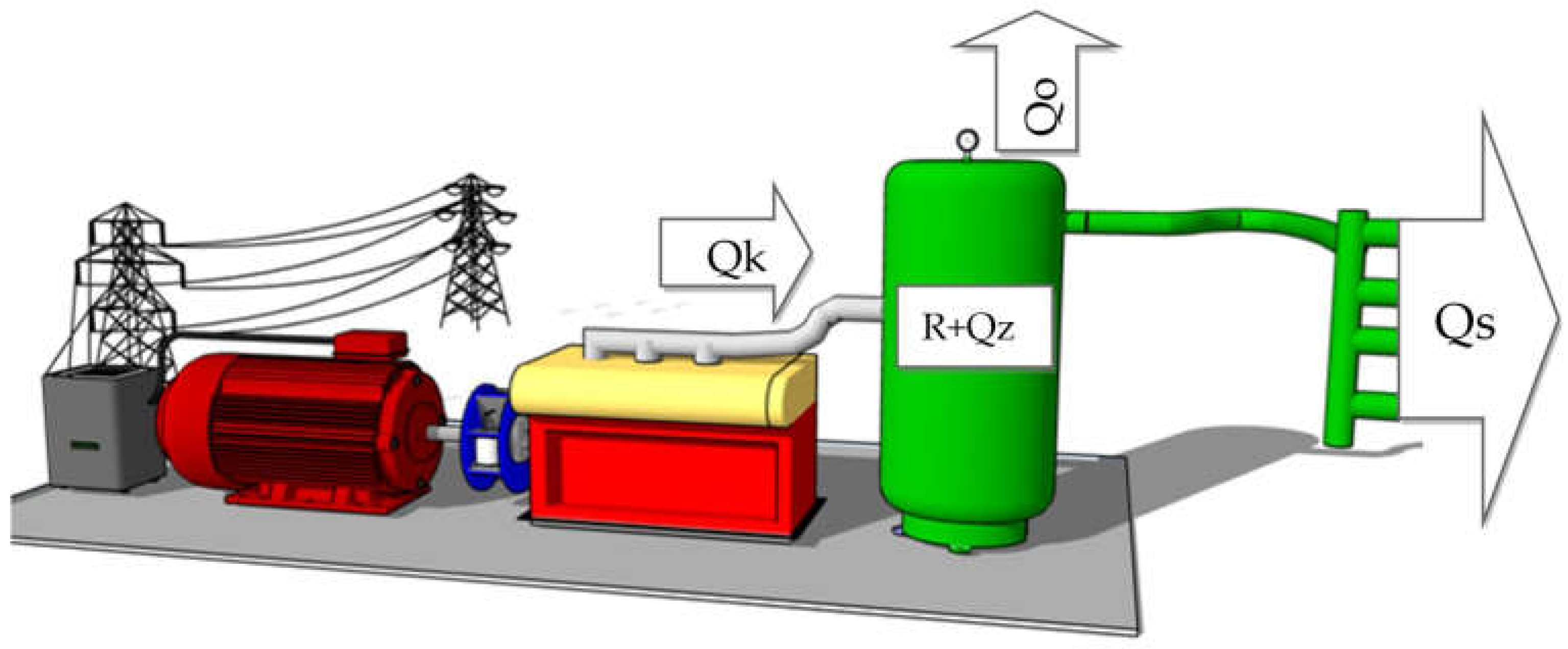
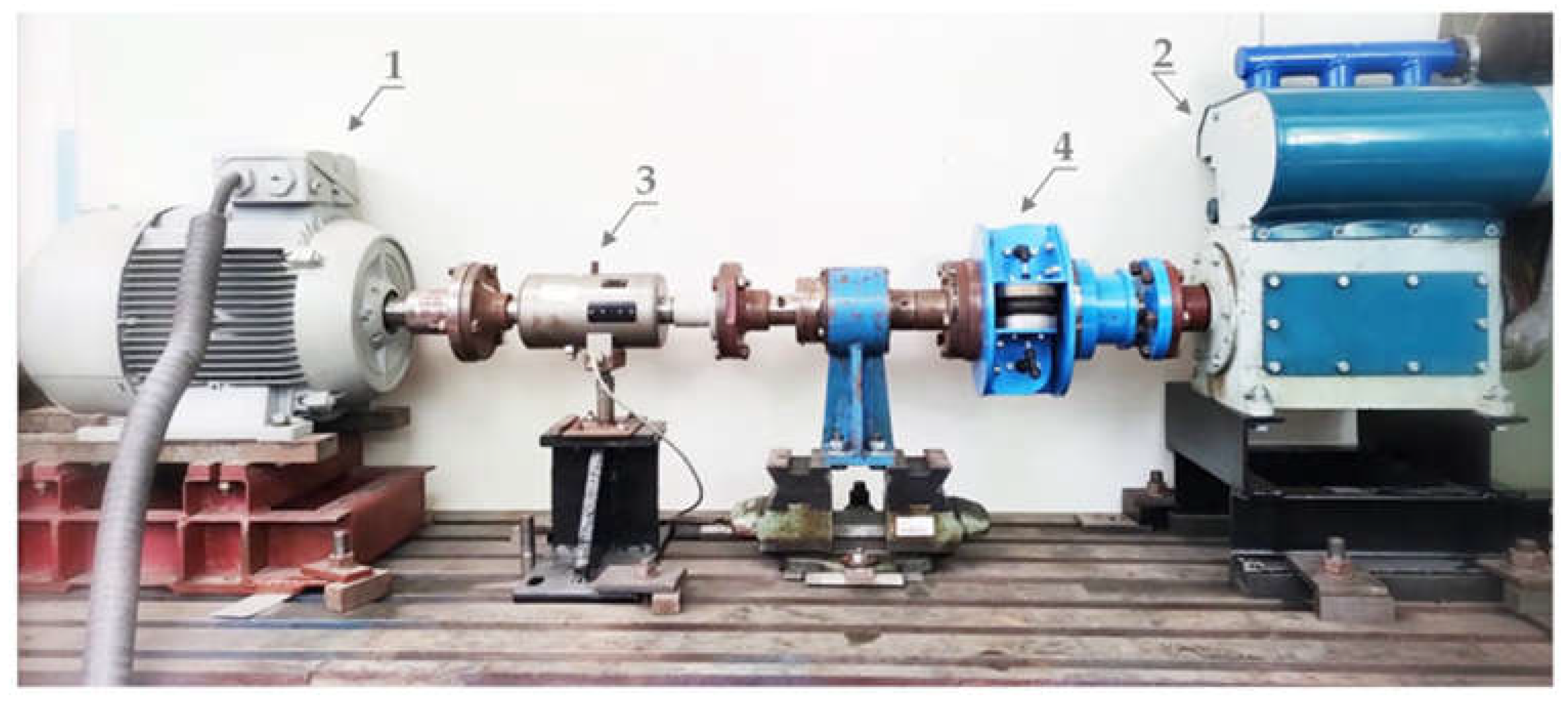
  • Three-phase asynchronous electric motor: operating speeds vary by frequency changer SIEMENS with vector control, type: 1LE10011DB234AF4-Z; nominal power: 11 kW; nominal operating speed: 1470 rpm; number of poles: 4.
  • Three-cylinder air compressor: type: ORLIK 3JSK-75; volume power: 50 m3h−1
    number of cylinders: 3; cylinder diameter: 82 mm; piston stroke: 70 mm
    maximum overpressure: 10 bars.
  • Torque sensor: MOM Kalibergyár, type: 7934; measurement range: 0 ÷ 500 Nm with accuracy 0.5 Nm.
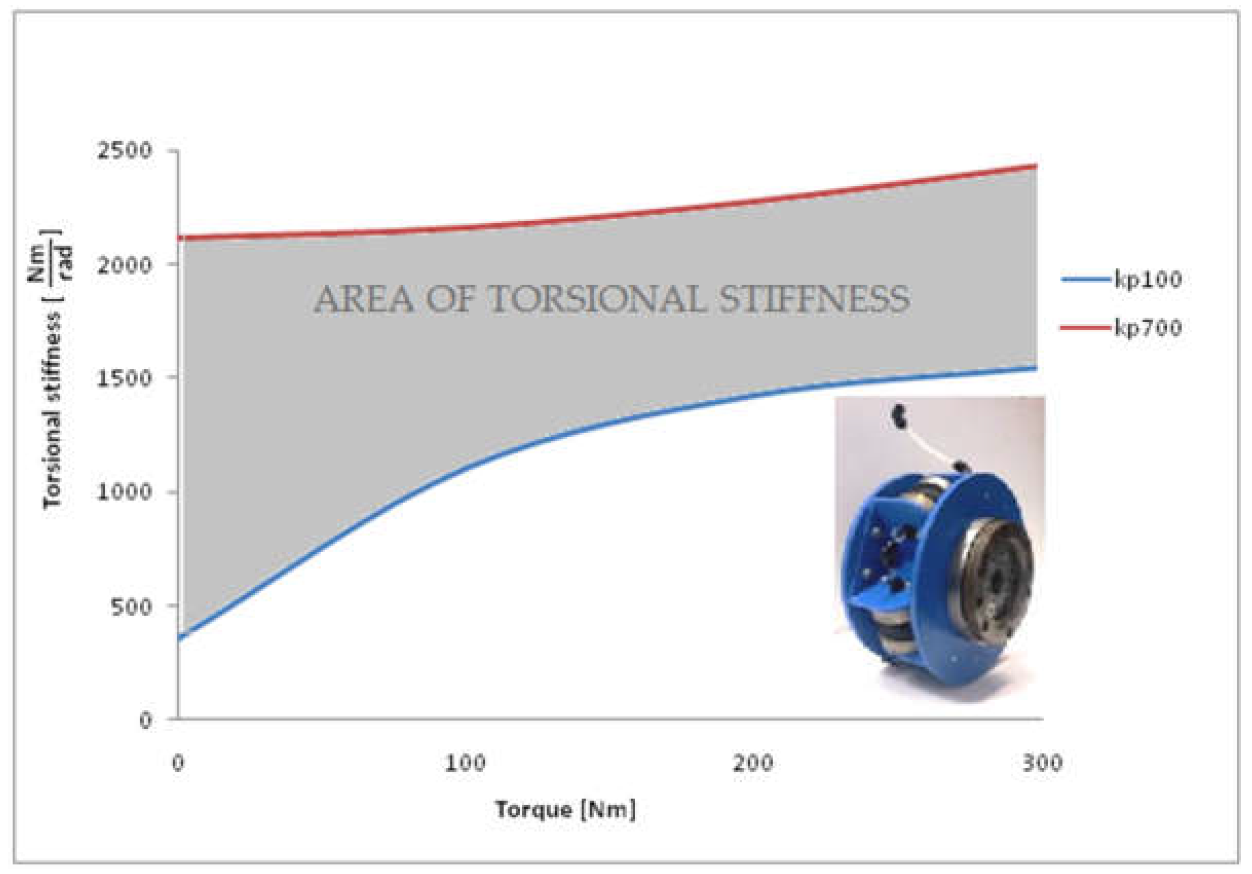
  • Pneumatic tuner: type: 4-1/70-T-C; maximum diameter: 242 mm; spacing diameter: 152 mm; width: 129 mm; weight: 11.6 kg.
The performed experiments were evaluated by using a Hottinger measuring apparatus: type: Quantum MX 840 with eight individual measurement channels and individual sample rates up t 40 kS/s per channel and with a 24-bit A/D converter per channel and supply voltage for active transducers (DC): 5–24 V, CAN bus Input/Output to which the torque sensor was connected.
The measured and evaluated variable was the dynamic component of the torque between the electric motor and the compressor. This dynamic component is the main source of torsional vibration and the main source of dynamic strain. To evaluate the dynamic torque, we used an effective value of vibrations. This value reflects the dynamic power of the dynamic torque, and it is therefore suitable for comparing the torsional vibration magnitude. The measurement was provided for two modes in which dynamic torque values were measured. In the first mode, the mechanical system worked in the operating speed from 200 rpm to 1000 rpm. The change of speed was ensured by the frequency control of the electric motor speed. The second mode was the variable operation of the compressor. In this mode, we investigated three modes of variability. The first mode was the operation of all three cylinders. In the second mode, one cylinder was deactivated, and in the third mode, two cylinders were deactivated. The cylinder deactivation was performed by means of the compressor suction valve locking. This suction valve arrest prevented compressed air from compressing the compressed air off.

5. Results and Discussion

Conventional mechanical systems with compressors are operating at constant speeds. By our first experimental measurement procedure we performed on the mechanical system a measurement with working ranges from 200 rpm to 1000 rpm. We measured values during different torque stiffness of the pneumatic tuner. For the sake of clarity, Figure 11 shows the dynamic torque dynamics only for the four torsional stiffness values of kp100, kp300, kp500 and kp700 achieved by coupling pressure with values of 100 kPa, 300 kPa, 500 kPa and 700 kPa, respectively. In Figure 11, we can clearly see the resonance area of the mechanical system for individual torsional stiffness. Figure 11 below shows the resonance area for individual changing stiffness. With a decreasing torsional stiffness value, the resonant area moves towards lower revolutions. This state is caused by the change of the natural frequency of the mechanical system as described in Equations (2)–(4).
For each course area, concretely on the left side from resonance is the so-called “under-resonance area”, and on the right side from the resonance is the so-called “over-resonance area”. Currently, mechanical systems with piston machines are designed to work in the over-resonance area. In this area, the dynamic stresses are lower than in the under-resonance area. This also confirms the progress shown in Figure 11. The dynamic load values in the under-resonance area are two, whereas they are three times the dynamic load values in the over-resonance area. In Figure 12, dynamic torque values are shown as a function of the torsional stiffness of the pneumatic tuner for the various operating speed of the mechanical system. Analyzing Figure 11, we can state that, when operating the mechanical system for speeds from 200 to 500 rpm, it is more convenient for the mechanical system to be fitted with a coupling with higher torsional stiffness, because in this case it is possible to achieve lower dynamic torque. For speeds ranging from 700 to 1000 rpm, a pneumatic tuner with a lower torsional stiffness value is more suitable. Interestingly, however, the pneumatic tuner of kp100 is not suitable, while a coupling with torsional stiffness kp200 is. The operating speed of value 600 rpm has a very specific course because it has two extremes, one minimum and one maximum. This means that a coupling torque stiffness kp300 is suitable for these speeds to achieve a minimum load. For torsional stiffness kp600, the dynamic load is maximum, but the trend of course shows that, while stiffness increases from this value, the dynamic load decreases.
From the analysis of the results of the experimental measurements in Figure 11 and Figure 12, we can further state that, for our first case, when we modify the compressor performance by changing the whole system operating speed, it is suitable from the point of view of torsional oscillation for the system to operate in the over-resonance area; for this case, there is a sufficiently high flexible coupling. Such a high flexible coupling moves the resonant area to a lower speed, and it increases the working area of the compressor. However, we are considering using the system in the under-resonance area. In the under-resonance area, the dynamic load is higher than in the over-resonance area, but it will bring us a much larger working range of the mechanical system and thus much greater control of the volume performance of the compressor. In this case, there would also be a resonance area within the work area, but it can be effectively shifted as necessary by varying the torsional stiffness of the pneumatic tuner as shown in Figure 11 and Figure 12.
The second alternative we examined was the variability of the compressor. Variability of the compressor consisted of the working mode—one or two cylinders. Such a cylinder shutdown reduces both the compressor stroke volume and the compressor volume capacity. In Figure 13, we show the dynamic torque dependence on the torsional stiffness of the pneumatic tuner. We studied this dependency for various rotational modes of compressor operation. The revolutions of the mechanical system ranged from 200 rpm to 1000 rpm. As shown in Figure 13, when one cylinder is deactivated, the dynamic load increases two or three times. We can divide the course into three groups. The first group is the rotation speeds from 200 to 500 rpm for which the torsional stiffness of the coupling is more suitable. The second group is the speed of 800 to 1000 rpm, for which a coupling with a lower torsional stiffness is also more suitable. The third group produces rotational speeds of 600 rpm and 700 rpm. These developments are interesting because of the two extremes. These are the extremes of the local minimum and local maximum, which represent the minimum and maximum dynamic stresses at different torsional stiffness values, respectively.
When comparing the operation of the compressor with all cylinders in Figure 12 and the operation of the compressor with the one-cylinder deactivation in Figure 13, we can make several observations:
  • The courses of all cylinders are similar to courses of one-cylinder deactivation. In the event of a single cylinder being deactivated, the progresses were moved to the area of higher dynamic load values.
  • If the mechanical system worked with all cylinders’ activation in the over-resonance area with the most suitable torsional stiffness kp200, then when one cylinder is deactivated, the value of the dynamic load would increase for some speeds almost three times.
  • The values of the dynamic stress at disconnected cylinder in the over-resonance area in Figure 13 are higher than the values of the dynamic load at the run of all cylinders in the under-resonance area in Figure 12.
  • In the case of a cylinder deactivation, the variance of values in the under-resonance area is less than the variance of the dynamic load values in the over-resonance area.
  • The multiplication of the increase in dynamic oscillation with the cylinder deactivation in the under-resonance area compared to all cylinders running is less than a multiple of the increase in the work of the mechanical system in the over-resonance area when all cylinders are working, along with one-cylinder deactivation.
Dynamic load of the mechanical system was also investigated for deactivation of two compressor cylinders. The results of this research are shown in Figure 14. For the sake of clarity, we only describe the speeds from 500 rpm to 1000 rpm. From the courses, it is seen that the dynamic load values are higher than those during running of all cylinders, but less than during the running of deactivation of one cylinder. Dynamic load values do not have a large variation for individual speed courses.

6. Conclusions

The aim of the article is demonstration of the innovative solution of torsional vibration reduction by application of pneumatic tuner in shipping piston devices. Pneumatic tuner, which we have developed, offers an innovative solution to reduce the torsional vibration in mechanical drives whose working mode is characterized by a change in volume performance. In order to verify the impact of the pneumatic tuner to reduce torsional vibrations, we used a mechanical drive in which a piston compressor is integrated. The volume performance of the piston compressor was changed in two alternatives. The first alternative changed the operating speed of the compressor and the second alternative used the variable of the deactivation of the cylinder of the compressor pistons. The pneumatic tuner is able to contribute a reduction of the dynamic load of the mechanical system due to the possibility of changing the torsional stiffness, as can be seen from the results and analysis:
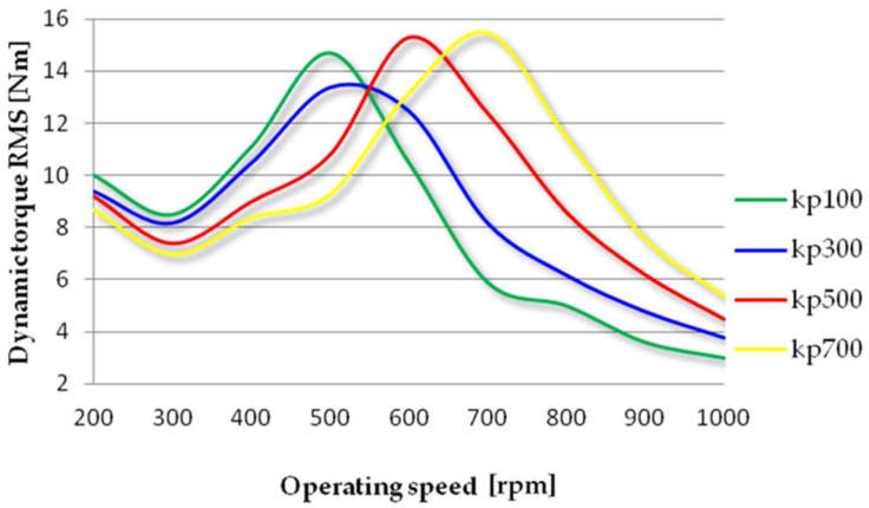
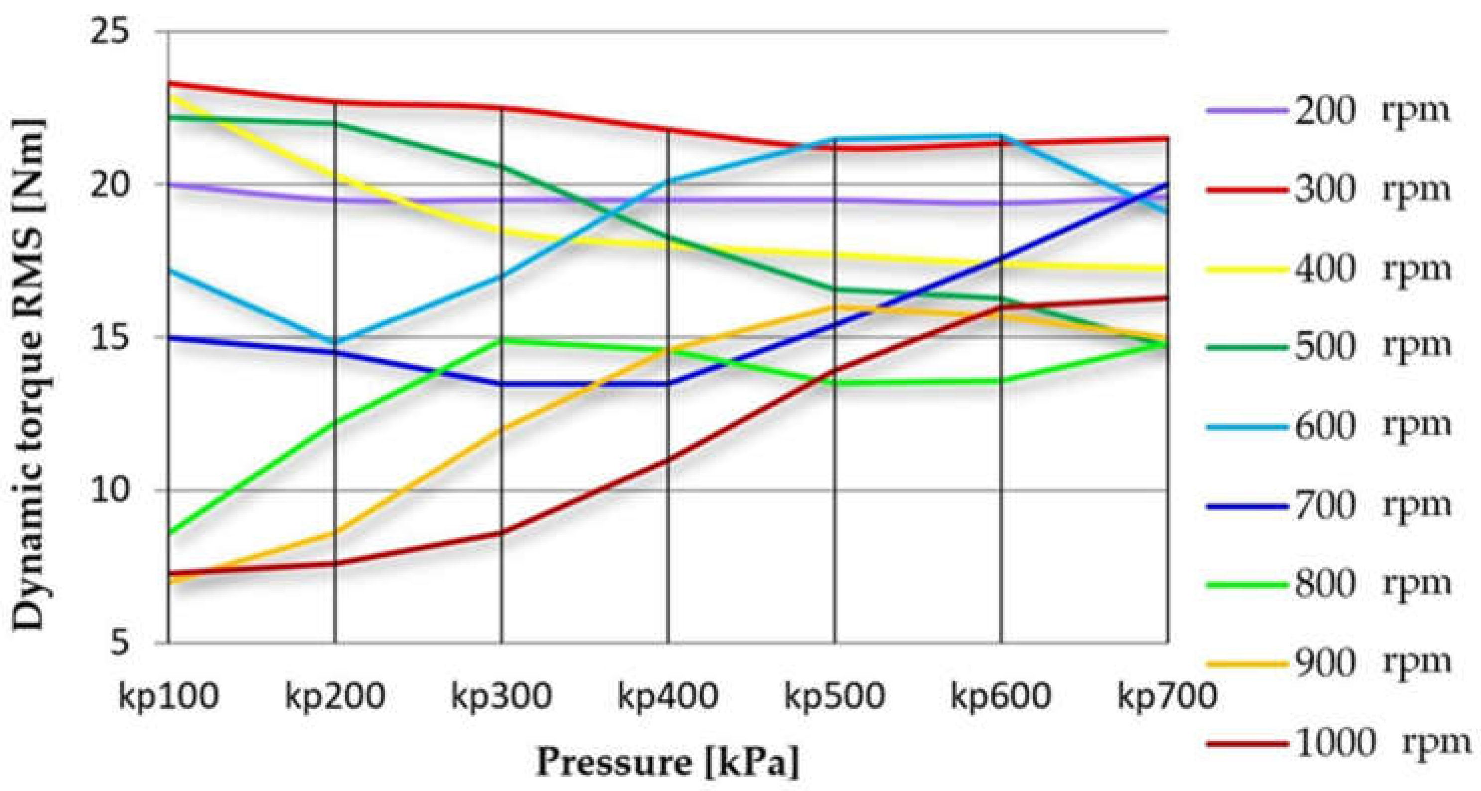
  • From Figure 11, it can be seen that resonance area is dependent on torsional stiffness of the pneumatic tuner.
  • If torsion stiffness is variable, it is possible to change a torsional vibration in resonance. For example, if torsional stiffness has a value of kp700, the resonant area exists at operating speed 700 rpm. Torsional vibrations have reached value of 15 Nm. By decreasing the torsional stiffness in the resonance area up to kp100, torsional vibrations will decrease to a value of 5 Nm. This fact can be considered as a three times vibration reduction. Such torsional vibration reduction by means of a smooth change in torsional stiffness can be realized over a wide range of operating speeds.
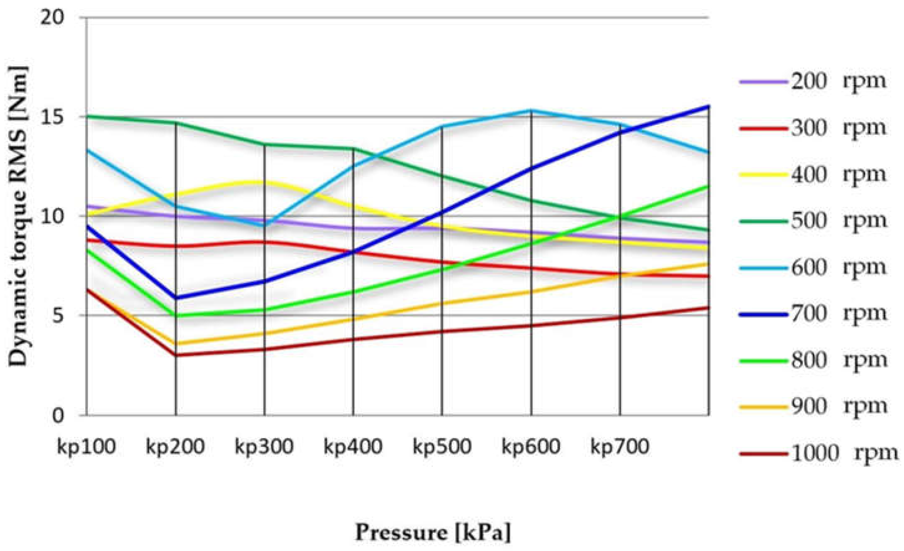
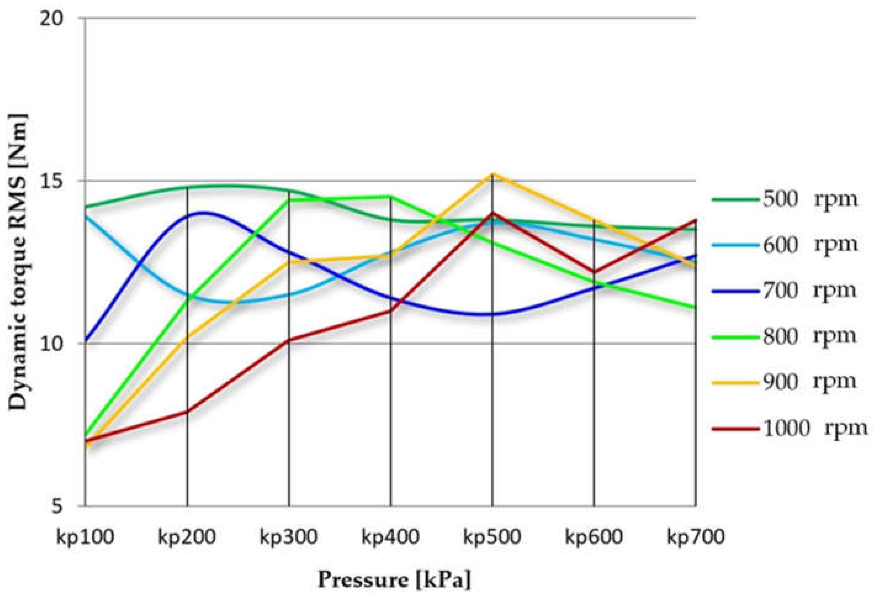
  • Reduction of torsional vibrations can be also effectively carried out in cylinder deactivation. For example, at operating speed of 700 rpm, it is suitable to use a pneumatic tuner with torsional stiffness of kp200 at which the value of torsional vibration is 6 Nm in the operation mode of all cylinders. If we deactivate one cylinder at this operating speed, the value of the torsional vibration will increase to 14 Nm, and after two-cylinder deactivation, the value of the torsional vibration will reach a value of 13 Nm. Immediately, we can appropriately adjust the torsional stiffness as needed. For example, in the case with one-cylinder deactivation, the torsional stiffness will be held at kp400, and in case with two-cylinder deactivation, the torsional stiffness will be held at kp500. In these cases, we notice a decrease of 13 Nm and 11 Nm lower torsional vibrations, respectively. A change in torsional stiffness in order to minimize torsional vibrations can be realized smoothly during the working time of the mechanical drive.
From the results, we found that a conventional low-stiffness coupling would also be useful for the first alternative of operation of the mechanical system operating at speed change. It would be able to move its natural frequency and, hence, the resonant area under the operating ranges of the mechanical system.
However, such a solution does not allow for the mechanical system to operate in the under-resonance area. When we increase the working range of the mechanical system and under-resonance area, it also would mean a resonance area in the work area in a conventional high flexible coupling. Only a pneumatic tuner with varying torsional stiffness is able to move the natural frequency of the mechanical system so that there is no resonance in the working area. The pneumatic tuner allows us to change natural frequency during the operation of the mechanical system. This change can provide movement of the resonance area under and over operating speed, which means the creation of a mechanical system that will operate over a wide range of operating speeds.
Demonstrating the measurements for the compressor’s second mode of operation, i.e., for the variable deactivation of the compressor cylinders, a conventional low-stiffness coupling is not sufficient. However, the pneumatic tuner is in this case suitable, because of the changing torsional stiffness, which adapts our natural frequency of the mechanical system to reach the lowest possible values of the dynamic load of the mechanical system. From the above findings follows that only the pneumatic tuners in which it is possible to change the torsional stiffness are suitable for mechanical systems to operate in a mode characterized by a change in volume performance. The pneumatic tuner we have developed has the coupling that allows for this change. It is important that the pneumatic tuner makes this change possible during the mechanical system operation, without the need of shutdown and intervention by disassembly and assembly of a new coupling. Such a pneumatic tuner, in which we are able to change the torsion stiffness during the operation of the mechanical system, can be termed as a continually pneumatic tuner in the future.
Our further research into the reduction of torsional oscillation in mechanical systems whose volume performance is optimized will focus on developing regulatory systems for a continually pneumatic tuner, other new types of pneumatic tuners and new materials used in such tunable flexible couplings.

Author Contributions

Conceptualization, L.Ž. and R.G.; methodology, R.G.; software, P.K.; validation, L.Ž., M.K. and R.G.; formal analysis, R.G.; investigation, L.Ž., J.K. and M.U.; resources, R.G.; data curation, J.K. and M.U.; writing—original draft preparation, L.Ž. and R.G.; writing—review and editing, L.Ž. and R.G.; visualization, L.Ž., M.K. and R.G.; supervision, R.G.; project administration, R.G.; funding acquisition, R.G. All authors have read and agreed to the published version of the manuscript.

Funding

This research was funded by VEGA 1/0528/20, KEGA 029TUKE-4/2021.

Institutional Review Board Statement

Not applicable.

Informed Consent Statement

Not applicable.

Data Availability Statement

Not applicable.

Acknowledgments

This work is a part of these projects VEGA 1/0528/20, KEGA 029TUKE-4/2021.

Conflicts of Interest

The authors declare no conflict of interest.

References

  1. Galdo, M.I.L. Marine Engines Performance and Emissions. J. Mar. Sci. Eng. 2021, 9, 280. [Google Scholar] [CrossRef]
  2. Chaban, A.; Perzyński, T.; Popenda, A.; Figura, R.; Levoniuk, V. Mathematical Modeling of Transient Processes in the Susceptible Motion Transmission in a Ship Propulsion System Containing a Shaft Synchronous Generator. Energies 2022, 15, 3266. [Google Scholar] [CrossRef]
  3. Piňosová, M.; Andrejiová, M.; Lumnitzer, E. Synergistic effect of risk factors and work environmental quality. Qual. Access Success 2018, 19, 154–159. [Google Scholar]
  4. Michaelides, M.P.; Herodotou, H.; Lind, M.; Watson, R.T. Port-2-Port Communication Enhancing Short Sea Shipping Performance: The Case Study of Cyprus and the Eastern Mediterranean. Sustainability 2019, 11, 1912. [Google Scholar] [CrossRef] [Green Version]
  5. Lewitzke, C.; Lee, P. Application of Elastomeric Components for Noise and Vibration Isolation in the Automotive Industry. In Proceedings of the SAE 2001 Noise & Vibration Conference & Exposition, Traverse City, MI, USA, 30 April–3 May 2001. SAE Technical Paper. [Google Scholar] [CrossRef]
  6. Wojnar, G.; Burdzik, R.; Wieczorek, A.N.; Konieczny, Ł. Multidimensional Data Interpretation of Vibration Signals Registered in Different Locations for System Condition Monitoring of a Three-Stage Gear Transmission Operating under Difficult Conditions. Sensors 2021, 21, 7808. [Google Scholar] [CrossRef]
  7. Grega, I.; Grega, R.; Homisin, J. Frequency of free vibration in systems with a power-law restoring force. Bull. Pol. Acad. Sci. Tech. Sci. 2021, 69, e136723. [Google Scholar] [CrossRef]
  8. UNCTAD. United Nations Conference on Trade and Development. 2021. Available online: https://unctad.org/webflyer/review-maritime-transport-2021 (accessed on 14 December 2022).
  9. COP26. United Nations Climate Change Conference. 2021. Available online: https://ukcop26.org (accessed on 10 December 2022).
  10. ESPO. Top 10 Environmental Priorities of EU Ports 2020. EcoPorts Publications. 2020. Available online: https://www.ecoports.com (accessed on 10 December 2022).
  11. IMO (International Maritime Organization). Introduction to IMO. Available online: http://www.imo (accessed on 12 December 2022).
  12. Marine Environment Protection Committee (MEPC) 77, IMO. 2021. Available online: https://www.imo.org (accessed on 14 December 2022).
  13. A European Green Deal. 2021. Available online: https://ec.europa.eu/info/strategy/priorities-2019-2024/european-green-deal_en (accessed on 12 December 2022).
  14. Union, Council of the European. “ST 12249 2022 Init, Proposal for a Council Regulation on an Emergency Intervention to Address High Energy Prices.” Photo of Publications Office of the European Union, Publications Office of the European Union, 14 September 2022. Available online: op.europa.eu/en/publication-detail/-/publication/74a1227a-3448-11ed-8b77-01aa75ed71a1/language-en (accessed on 14 December 2022).
  15. Puškár, M.; Jahnátek, A.; Kádárová, J.; Šoltésová, M.; Kovanič, Ľ.; Krivosudská, J. Environmental study focused on the suitability of vehicle certifications using the new European driving cycle (NEDC) with regard to the affair “dieselgate” and the risks of NOx emissions in urban destinations. Air Quality. Atmos. Health 2018, 12, 251–257. [Google Scholar] [CrossRef]
  16. Kulka, J.; Mantic, M.; Fedorko, G.; Molnar, V. Failure analysis concerning causes of wear for bridge crane rails and wheels. Eng. Fail. Anal. 2020, 110, 104441. [Google Scholar] [CrossRef]
  17. Puškár, M.; Jahnátek, A.; Kuric, I.; Kádárová, J.; Kopas, M.; Šoltésová, M. Complex analysis focused on influence of biodiesel and its mixture on regulated and unregulated emissions of motor vehicles with the aim to protect air quality and environment. Air Quality. Atmos. Health 2019, 12, 855–864. [Google Scholar] [CrossRef]
  18. Pástor, M.; Živčák, J.; Puškár, M.; Lengvarský, P.; Klačková, I. Application of Advanced Measuring Methods for Identification of Stresses and Deformations of Automotive Structures. Appl. Sci. 2020, 10, 7510. [Google Scholar] [CrossRef]
  19. Turoń, K.; Czech, P.; Tóth, J. Safety and security aspects in shared mobility systems. Sci. J. Silesian Univ. Technol. Ser. Transp. 2019, 104, 169–175. [Google Scholar] [CrossRef]
  20. Liptai, P.; Lumnitzer, E.; Moravec, M.; Piňosová, M. Analysis and Classification of Noise Sources of Conveyor Systems by Sound Visualizing on the Postal Package Sorting Line. Adv. Sci. Technol. Res. J. 2018, 12, 172–176. [Google Scholar] [CrossRef]
  21. Piňosová, M.; Andejiová, M.; Liptai, P.; Lumnitzer, E. Objective and subjective evaluation of the risk physical factors near to conveyor system. Adv. Sci. Technol. Res. J. 2018, 12, 188–196. [Google Scholar] [CrossRef]
  22. Lamas Galdo, M.I.; Rodriguez García, J.D.; Rebollido Lorenzo, J.M. Numerical Model to Analyze the Physicochemical Mechanisms Involved in CO2 Absorption by an Aqueous Ammonia Droplet. Int. J. Environ. Res. Public Health 2021, 18, 4119. [Google Scholar] [CrossRef]
  23. Moravec, M.; Ižaríková, G.; Liptai, P.; Badida, M.; Badidova, A. Development of psychoacoustic model based on the correlation of the subjective and objective sound quality assessment of automatic washing machines. Appl. Acoust. 2018, 140, 178–182. [Google Scholar] [CrossRef]
  24. Wojnar, G.; Irlik, M. Multicriteria train running model and simulator for railway capacity assessment. Transp. Probl. Int. Sci. J. 2022, 17, 199–212. [Google Scholar] [CrossRef]
  25. Czech, P.; Turoń, K.; Barcik, J. Autonomous vehicles: Basic issues. Sci. J. Sil. Univ. Technol. Ser. Transp. 2018, 100, 15–22. [Google Scholar] [CrossRef]
  26. Haris, A.; Motato, E.; Theodossiades, S.; Rahnejat, H.; Kelly, P. A study on torsional vibration attenuation in automotive drivetrains using absorbers with smooth and non-smooth nonlinearities. Appl. Math. Model. 2016, 46, 674–690. [Google Scholar] [CrossRef] [Green Version]
  27. Haris, A.; Motato, E.; Mohammadpour, M.; Theodossiades, S.; Rahnejat, H. On the effect of multiple parallel nonlinear absorbers in palliation of torsional response of automotive drivetrain. Int. J. Non-Linear Mech. 2017, 96, 22–35. [Google Scholar] [CrossRef] [Green Version]
  28. Motato, E.; Haris, A.; Theodossiades, S.; Mohammadpour, M.; Rahnejat, H. Targeted energy transfer and modal energy redistribution in automotive drivetrains. Nonlinear Dyn. 2017, 87, 169–190. [Google Scholar] [CrossRef] [Green Version]
  29. Zink, M.; Hausner, M. The centrifugal pendulum-type absorber. ATZ Worldw. 2009, 111, 42–47. [Google Scholar] [CrossRef]
  30. Manchi, V.; Sujatha, C. Torsional vibration reduction of rotating shafts for multiple orders using centrifugal double pendulum vibration absorber. Appl. Acoust. 2021, 174, 107768. [Google Scholar] [CrossRef]
  31. Liu, C.C.; Jing, X.J.; Chen, Z. Band stop vibration suppression using a passive X-shape structured lever-type isolation system. Mech. Syst. Sig. Process. 2016, 68–69, 342–353. [Google Scholar] [CrossRef]
  32. Liu, C.C.; Jing, X.J. Nonlinear vibration energy harvesting with adjustable stiffness, damping and inertia. Nonlinear Dyn. 2016, 88, 79–95. [Google Scholar] [CrossRef]
  33. Berbyuk, V. Weight-Vibration Pareto Optimization of a Triple Mass Flywheel for Heavy-Duty Truck Powertrains. Machines 2020, 8, 50. [Google Scholar] [CrossRef]
  34. Jang, D.I.; Yun, G.E.; Park, J.-E.; Kim, Y.-K. Designing an attachable and power-efficient all-in-one module of tunable vibration absorber based on magnetorheological elastomer. Smart Mater. Struct. 2018, 27, 085009. [Google Scholar] [CrossRef]
  35. Lee, K.H.; Park, J.E.; Kim, Y.K. Design of a stiffness variable flexible coupling using magnetorheological elastomer for torsional vibration reduction. J. Intell. Mater. Syst. Struct. 2019, 30, 2212–2221. [Google Scholar] [CrossRef]
  36. Xiang, B.; Wong, W. Electromagnetic vibration absorber for torsional vibration in high speed rotational machine. Mech. Syst. Signal Process. 2020, 140, 106639. [Google Scholar] [CrossRef]
  37. Synák, F.; Jakubovicová, L.; Klacko, M. Impact of the Choice of Available Brake Discs and Brake Pads at Different Prices on Selected Vehicle Features. Appl. Sci. 2022, 12, 7325. [Google Scholar] [CrossRef]
  38. Wieczorek, A.N.; Konieczny, Ł.; Burdzik, R.; Wojnar, G.; Filipowicz, K.; Kuczaj, M. A Complex Vibration Analysis of a Drive System Equipped with an Innovative Prototype of a Flexible Torsion Clutch as an Element of Pre-Implementation Testing. Sensors 2022, 22, 2183. [Google Scholar] [CrossRef]
  39. Kinnunen, K.; Laine, S.; Tiainen, T.; Viitala, R. Method for Adjusting Torsional Natural Frequencies of Powertrains with Novel Coupling Design. Machines 2022, 10, 162. [Google Scholar] [CrossRef]
  40. Krajnak, J.; Homisin, J.; Grega, R.; Kassay, P.; Urbansky, M. The failures of flexible couplings due to self-heating by torsional vibrations—Validation on the heat generation in pneumatic flexible tuner of torsional vibrations. Eng. Fail. Anal. 2021, 119, 104977. [Google Scholar] [CrossRef]
  41. Žuľová, L.; Grega, R.; Krajňák, J.; Fedorko, G.; Molnár, V. Optimization of noisiness of mechanical system by using a pneumatic tuner during a failure of piston machine. Eng. Fail. Anal. 2017, 79, 845–851. [Google Scholar] [CrossRef]
  42. Li, M.; Khonsari, M.; Yang, R. Dynamics analysis of torsional vibration induced by clutch and gear set in automatic transmission. Int. J. Automot. Technol. 2018, 19, 473–488. [Google Scholar] [CrossRef]
  43. Idehara, S.J.; Flach, F.L.; Lemes, D. Modeling of nonlinear torsional vibration of the automotive powertrain. J. Vib. Control. 2018, 24, 1774–1786. [Google Scholar] [CrossRef]
  44. Chen, L.; Zeng, R.; Jiang, Z. Nonlinear dynamical model of an automotive dual mass flywheel. Adv. Mech. Eng. 2015, 7, 1687814015589533. [Google Scholar] [CrossRef]
  45. Albers, A. Advanced Development of Dual Mass Flywheel (DMFW) Design-Noise Control for Today’s Automobiles, Dring, 2006. Available online: https://www.schaeffler.com/remotemedien/media/_shared_media/08_media_library/01_publications/schaeffler_2/symposia_1/downloads_11/1_Dual_Mass_Flywheel_1.pdf (accessed on 14 December 2022).
  46. Faust, H. What Transmission Systems Can Do for Downsizing and Downspeeding of Powertrains and Cylinder Deactivation. In Proceedings of the VDI Conference Drivetrain for Vehicles, Friedrichshafen, Germany, 24–25 June 2014; VDI Reports no. 2218. VDI-Verlag: Düsseldorf, Germany, 2014; pp. 419–441. [Google Scholar]
  47. Scheidt, M.; Brands, C.; Lang, M.; Kuhl, J.; Günther, M.; Medicke, M.; Vogler, C. Statische und dynamische Zylinderabschaltung an 4- und 3-Zylindermotoren. In Proceedings of the Internationaler Motorenkongress, Baden-Baden, Germany, 24–25 February 2015. [Google Scholar]
  48. Lu, X.; Ding, C.; Ramesh, A.K.; Shaver, G.M.; Holloway, E.; McCarthy, J.J.; Ruth, M.; Koeberlein, E.; Nielsen, D. Impact of cylinder deactivation on active diesel particulate filter regeneration at highway cruise conditions. Front. Mech. Eng. 2015, 1, 9. [Google Scholar] [CrossRef] [Green Version]
  49. Ramesh, A.K.; Shaver, G.M.; Allen, C.M.; Nayyar, S.; Gosala, D.B.; Parra, D.C.; Koeberlein, E.; McCarthy, J.; Nielsen, D. Utilizing low airflow strategies, including cylinder deactivation, to improve fuel efficiency and aftertreatment thermal management. Int. J. Engine Res. 2017, 18, 1005–1016. [Google Scholar] [CrossRef]
  50. Homisin, J.; Kassay, P.; Puskar, M.; Grega, R.; Krajnak, J.; Urbansky, M.; Moravic, M. Continuous tuning of ship propulsion system by means of pneumatic tuner of torsional oscillation. Int. J. Marit. Eng. 2021, 158, A231–A238. [Google Scholar] [CrossRef]
  51. Wang, K.; Zhou, J.; Xu, D. Sensitivity analysis of parametric errors on the performance of a torsion quasi-zero-stiffness vibration isolator. Int. J. Mech. Sci. 2017, 134, 336–346. [Google Scholar] [CrossRef]
  52. Dong, G.; Zhang, X.; Xie, S.; Yan, B.; Luo, Y. Simulated and experimental studies on a high-static-low-dynamic stiffness isolator using magnetic negative stiffness spring. Mech. Syst. Signal Process. 2017, 86, 188–203. [Google Scholar] [CrossRef]
  53. Homišin, J.; Grega, R.; Kaššay, P.; Fedorko, G.; Molnár, V. Removal of systematic failure of belt conveyor drive by reducing vibrations. Eng. Fail. Anal. 2019, 99, 192–202. [Google Scholar] [CrossRef]
Figure 1. Scheme of piston compressor drive system.
Jmse 11 00261 g001
Figure 2. Graph of traditional operating process of piston compressor.
Jmse 11 00261 g002
Figure 3. Graph of optimized operation process of piston compressor.
Jmse 11 00261 g003
Figure 4. Scheme of masses of piston compressor drive system.
Jmse 11 00261 g004
Figure 5. Two-degree-of-freedom simplification of a mechanical system.
Jmse 11 00261 g005
Figure 6. Frequency amplitude spectrum without deactivated cylinders in the compressor.
Jmse 11 00261 g006
Figure 7. Frequency amplitude spectrum with deactivation of one cylinder in the compressor.
Jmse 11 00261 g007
Figure 8. Frequency amplitude spectrum with deactivation of two cylinders in the compressor.
Jmse 11 00261 g008
Figure 9. Pneumatic tuner and its torsional stiffness properties.
Jmse 11 00261 g009
Figure 10. Mechanical drive with a piston compressor: Variable speed electric motor (1), variable operating speed compressor (2), torque sensor (3), pneumatic tuner (4).
Jmse 11 00261 g010
Figure 11. Measurement of variable resonance area for operating range—a run of all cylinders.
Jmse 11 00261 g011
Figure 12. Measurement in range of operating speed—a run of all cylinders.
Jmse 11 00261 g012
Figure 13. Measurement during constant operating speed with one cylinder deactivation.
Jmse 11 00261 g013
Figure 14. Measurement during constant operating speed with two-cylinder deactivation.
Jmse 11 00261 g014
Disclaimer/Publisher’s Note: The statements, opinions and data contained in all publications are solely those of the individual author(s) and contributor(s) and not of MDPI and/or the editor(s). MDPI and/or the editor(s) disclaim responsibility for any injury to people or property resulting from any ideas, methods, instructions or products referred to in the content.

