1. Introduction
Transoceanic ships of significant size are one of the most important logistical components for both passenger and cargo naval transportation. With an increasingly global business, naval transportation is being used more and more by many companies around the world. Three basic properties are connected to this type of transportation: high fuel consumption, long routes connected with long-term operation times, and unfavourable emissions at high levels. The International Maritime Organization (IMO) announced new rules for reducing sulphur oxide (SOx) and nitrogen oxide (NOx) emissions caused by transoceanic ships, which are several times more polluting than internal combustion engine vehicles [
1].
Marine engines use heavy fuel oil (HFO), which causes high pollution during its combustion. Therefore, marine diesel engine producers have tried in recent years to develop new types of engines, mainly for the reduction of harmful emissions produced during engine operation. One of the solutions is the usage of alternative and clean fuels, e.g., biodiesel. Biodiesel has many advantages: it is a sustainable natural fuel, has a very low sulphur and aromatic hydrocarbon content, a high cetane number, very good lubricity, a high ignition point, the ability to degrade biologically, and is non-toxic. Another big advantage of biodiesel is its application in clear form or as a mixture, which does not require serious or no modification to existing diesel engines used in marine transportation. Biodiesel has some drawbacks, including poor fuel efficiency, high solidification point, and high viscosity.
Many studies have been conducted all over the world to investigate the environmental impact of biodiesel. The studies show positive results of biodiesel testing in terms of a reduced amount of CO emissions, PM matter, level of sulphur, and hydrocarbons that are not burned during the combustion process in comparison to conventional diesel used in internal combustion engines. The biodiesel can be mixed with diesel oil nearly in any ratio due to its dissolvability in conventional diesel oil. In addition to the widely used rapeseed oil, waste cooking oil is becoming increasingly popular. The biodiesel application was tested in conventional engines used in motor vehicles [
2,
3,
4,
5].
Electric energy in transoceanic ships is produced by ancillary diesel engines, which produce emissions during operation that must be taken into consideration. Studies on the relationship between NO and NO
2 emissions are not being conducted in sufficient depth [
6,
7].
The study was performed to define the influence of biodiesel on the combustion process and the emitted emissions that are formed during ancillary diesel engine operation. The research applied mixtures with different ratios of biodiesel and ULSD-F (Ultra Low Sulphur Diesel-Fuel).
The main purpose of this study or research was to detect the influence of biodiesel in a high ratio with diesel oil on the combustion process and the amount of NOx emissions produced by the transoceanic ancillary diesel engines [
8,
9,
10].
2. The International Maritime Organization (IMO) Regulations
Emission standards for every engine type in a motor vehicle and industrial unit (also stationary) have been set. The three-tier structure for marine engines was accepted at a global level in 2008 by the Marine Environment Protection Committee (MEPC) as a part of the International Maritime Organisation (IMO), which sets progressively tighter NOx norms according to an engine’s installation date. The Annex VI NOx standards (
Table 1) have been applied to marine diesel engines.
NOx emissions of ships constructed on or after 1 January 2016, must be decreased to 3.4 g/kWh (Tier III) that operate in an Emission Control Area (ECA). Tier II regulations must be followed by ships operating outside of the EAC. Tier III represents an 80% reduction in NOx emissions over Tier I standards, which are equal to Euro IV’s NOx emissions for diesel and petrol vehicles. Therefore, Selective Catalytic Reduction (SCR) technology or other types of emissions reduction technology must be used. Special certification for Tier III marine engines is needed.
Sulphur content in marine fuel oil is also controlled by Annex VI for the detection of SOx emissions and PM emissions (controlled indirectly due to the exact PM emission value’s absence) during engine operation (
Table 2). Special fuel quality provisions exist for SOx Emissions Control Areas (SOx ECA or SECA). Limits for sulphur volume are shown in
Table 2.
HFO (Heavy Fuel Oil) is applicable in operation only if it meets the accepted sulphur limit.
Exhaust gas cleaning systems (EGCS), also known as scrubbers, are also needed (for SOx ECAs and globally) for sulphur emissions reduction.
3. Conditions and Experimental Engine
3.1. Tested Fuels and Experimental Engine
The research used an inline, 6 cylinder experimental ancillary diesel engine with direct injection fuelling. Tests were done with biodiesel and ULSD-F mixtures of different ratios. The used experimental engine is shown in
Figure 1. The experimental ancillary engine was connected to a dynamometer, which helped with testing different operation conditions [
11,
12,
13,
14,
15,
16,
17,
18,
19,
20,
21,
22,
23,
24,
25]. Technical specifications of the ancillary diesel engine used are: six cylinders, direct injection, turbocharged, and air-to-water cooled.
The specification of the used biodiesel met the regulations of European Standard EN 14214 (
Table 3), while the quantity of sulphur in ULSD-F was less than 10 ppm.
Experimental fuels consisted of biodiesel and ULSD-F mixed together in different ratios of 0, 50, 80, and 100% and marked as BU (0:100), BU (50:50), BU (80:20), and BU (100:0). The study also used different ratio values of mixtures; however, the aim of this research was to find the most suitable ones. A fuel mixture that contained less than 50% biodiesel did not meet the required outcomes in terms of emissions reduction, whereupon the mixture was considered unsatisfactory. Pure ULSD-F was the first type of fuel used, while clear diesel oil was used as the last type of fuel. Every fuel mixture’s fuel consumption was measured under the laboratory conditions shown in
Table 4.
3.2. Testing Conditions
Kistler, a measurement system, was used for cylinder internal pressure measurement in the first cylinder of the used ancillary diesel engine via a pressure converter [
18,
19,
20]. The crankshaft angular displacement sensor and the pressure sensor were interconnected by the amplifier. The connection between the pressure sensor and the crankshaft angular displacement sensor was important to obtain pressure values from the inside of the cylinder in the 0.5° range of the crankshaft angular displacement. The mobile emission testing device, TXM350 MARITIME, was used to measure NOx emissions produced during engine operation.
Measuring Device
During the experiment, the TXM350 MARITIME was used to analyse exhaust gases according to MARPOL Annexe VI and Technical Code 2008. A sampling of exhaust gas was done by a special sensor that is easy to install into the engine exhaust. This special electrochemical gas probe measures exhaust gas elements CO, CO
2, O
2, SO
2, and NOx (NO + NO
2 separately) very precisely with high accuracy and long-term stability. The certified IR measurement principle is used during CO
2 measuring.
Table 5 displays the measuring device’s technical specifications.
3.3. Testing Process
The testing was performed during stabilised engine operation with the aim of examining the influence of the fuel mixture (biodiesel—ULSD-F) on the combustion properties and on the NOx emissions production [
18,
21]. There were two stable operational engine speeds: 1200 and 1440 rpm, with various engine loads. Engine loads are shown in
Table 4. The tested ancillary engine ran for several minutes without any measurements to obtain high-precision measurement results by stabilising the temperatures of lubrication oil, cooling water, and exhaust gases. The cooling water temperature range was held between 75 and 85 °C, while the lubrication oil was held between 90 and 100 °C. The measurement was set to a three minute interval, during which the fuel consumption, NOx emissions, and exhaust gas temperatures were gauged. This interval was chosen on the basis of previous experiments performed during engine testing, and it represents a compromise in order to achieve the relevant results and at the same time not to wear out the engine too much, since during the testing process the tested engine’s durability is significantly reduced.
A tested ancillary diesel engine used two different fuel mixtures, and measurement results were averaged. To eliminate inaccuracies in the measurements, the test was done at least two times under stable operating conditions to obtain the best possible results [
22,
23,
24,
25,
26,
27,
28,
29,
30,
31,
32,
33,
34].
4. Measured Data
4.1. Engine Characteristics according to Different Tested Fuels
The speed of heat generation and the in-cylinder pressure values are shown in
Figure 2,
Figure 3,
Figure 4,
Figure 5,
Figure 6 and
Figure 7 as curves for various tested fuels. Through more than 100 test cycles in which values were averaged, the impact of random changes in pressure data values on operation cycles can be reduced [
31,
32,
33,
34,
35,
36,
37,
38,
39,
40,
41,
42,
43,
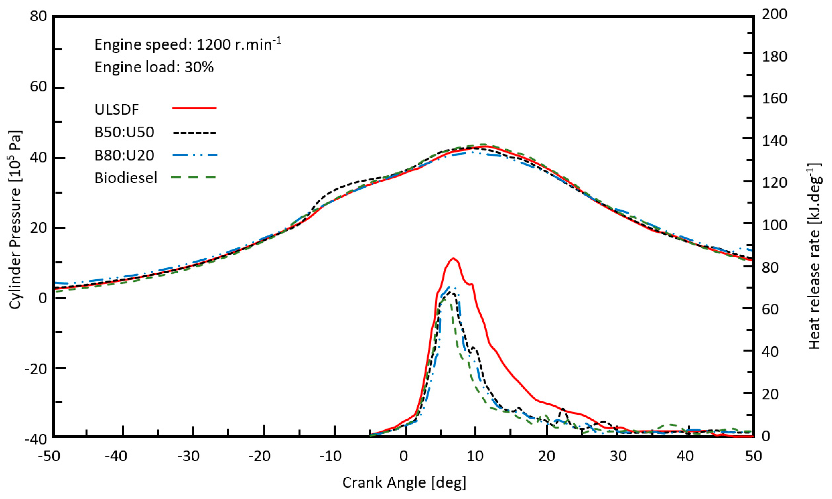
44]. As shown in
Figure 4 and
Figure 7, increasing the biodiesel ratio in tested fuels reduces in-cylinder pressure with higher engine loads. The heat generation speed curves differ in the ULSD-F regime and in the biodiesel regime. Tests showed that ULSD-F with a biodiesel mixture raised in-cylinder pressure earlier compared to pure ULSD-F usage. It is generally known that the higher cetane number of biodiesel and its laminar flame speed are much higher in comparison to ULSD-F. It is obvious that the maximum heat generation speed is significantly decreased with a higher ratio of biodiesel in the tested fuels, as well as with reduced ignition lag. As the experiment showed, the combustion of ULSD-F at 30% load of the maximum tested engine torque started in the crankshaft angle position of −1° Crank Angle (CA), while the biodiesel combustion process started at the angle position of −2° CA. At 90% load, ULSD-F started to be combusted at −4° CA, and the value for the biodiesel was −6° CA. The ignition lag was reduced approximately by 2° CA. Furthermore, as the biodiesel-to-ULSD-F ratio increased, the heat generation speed decreased.
4.2. Exhaust Gas Temperature Differences with Different Tested Fuels
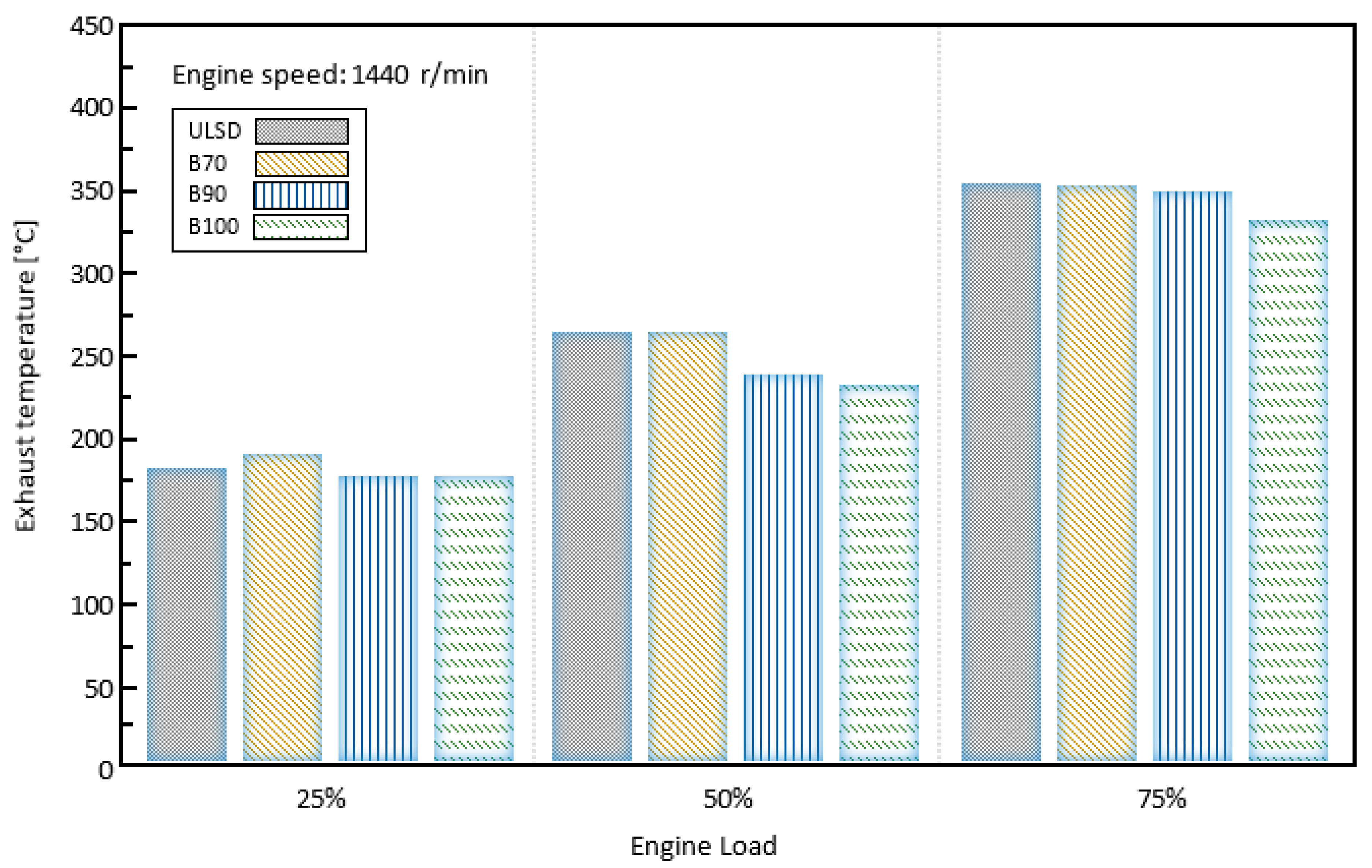
Emissions generation is influenced by the exhaust gases’ temperature, which is dependent on combustion efficiency.
Figure 8 and
Figure 9 show the temperatures of the exhaust pipe with different biodiesel ratios in the tested fuel mixtures. Obviously, engine load and higher engine speed influence (increase) exhaust pipe temperature; however, a higher biodiesel content in the tested mixture moderately reduces the temperature. With a low engine speed and load, the exhaust gas temperature is kept below 130 °C (
Figure 8). The exhaust gas temperature rises significantly with high engine speed and high engine load and can reach temperatures up to 385 °C or even more (
Figure 9). NOx emissions are also influenced by exhaust pipe temperature.
Figure 8 and
Figure 9 show an exhaust gas temperature reduction with higher biodiesel amounts in the mixture with diesel oil compared to pure ULSD-F. The heat generation process is slowed down by the lower amount of fuel in biodiesel. It is assumed that the improved combustion phase with biodiesel is a result of its reduced tendency to release heat at low temperatures and its oxygenated property, which allows the transition to fast heat release much earlier than with petroleum diesel.
The exhaust gas temperature reduction is possible thanks to the factors mentioned [
12,
13,
14,
15,
16,
17].
4.3. Tested Engine’s NOx Emissions with Different Tested Fuels
Diesel engines’ main pollutants are considered to be NOx emissions. The composition of NOx emissions is nitrogen dioxide (NO
2), nitrogen monoxide (NO), and nitrous oxide (N
2O) [
13]. NO emissions represent more than 60% of engine pollutants [
18,
19,
20,
21,
22]. Next are NO
2 emissions at 40%, and N
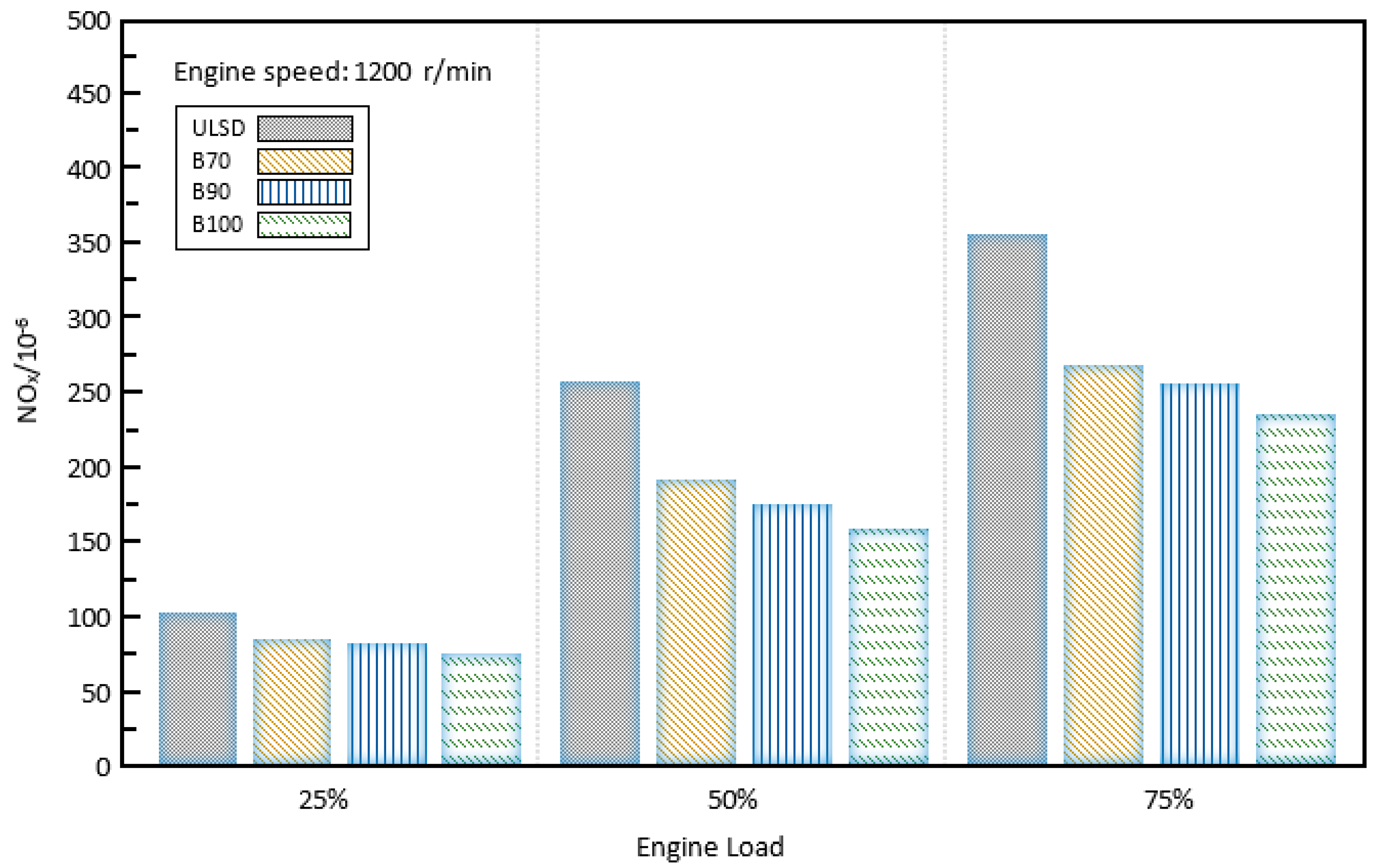
2O emissions are nominal. As a result, NOx emissions are the primary focus of this research. The air/fuel ratio influences the composition of NOx emissions primarily through ignition timing (delay) and air/fuel mixture temperature. As shown in
Figure 10 and
Figure 11, biodiesel content in the fuel mixture significantly influences the creation of NOx emissions. Increasing biodiesel volume considerably reduces the formation of NOx emissions. When the ULSD-F regime is compared to the pure biodiesel regime at a low engine load, there are significant differences in NOx formation (
Figure 10). Engine fuel with ULDS-F produces 108 ppm, while engine fuel with pure biodiesel produces about 80 ppm.
Higher generation of NOx emissions during engine operation relates to increasing engine speed and loads. Emissions values can reach a maximum of about 670 ppm in the case of ULSD-F and nearly 465 ppm in the pure biodiesel regime (
Figure 11). With rising engine load and engine speed, the exhaust gas temperature also rises, which is the main cause of the rise in global NOx emissions [
43].
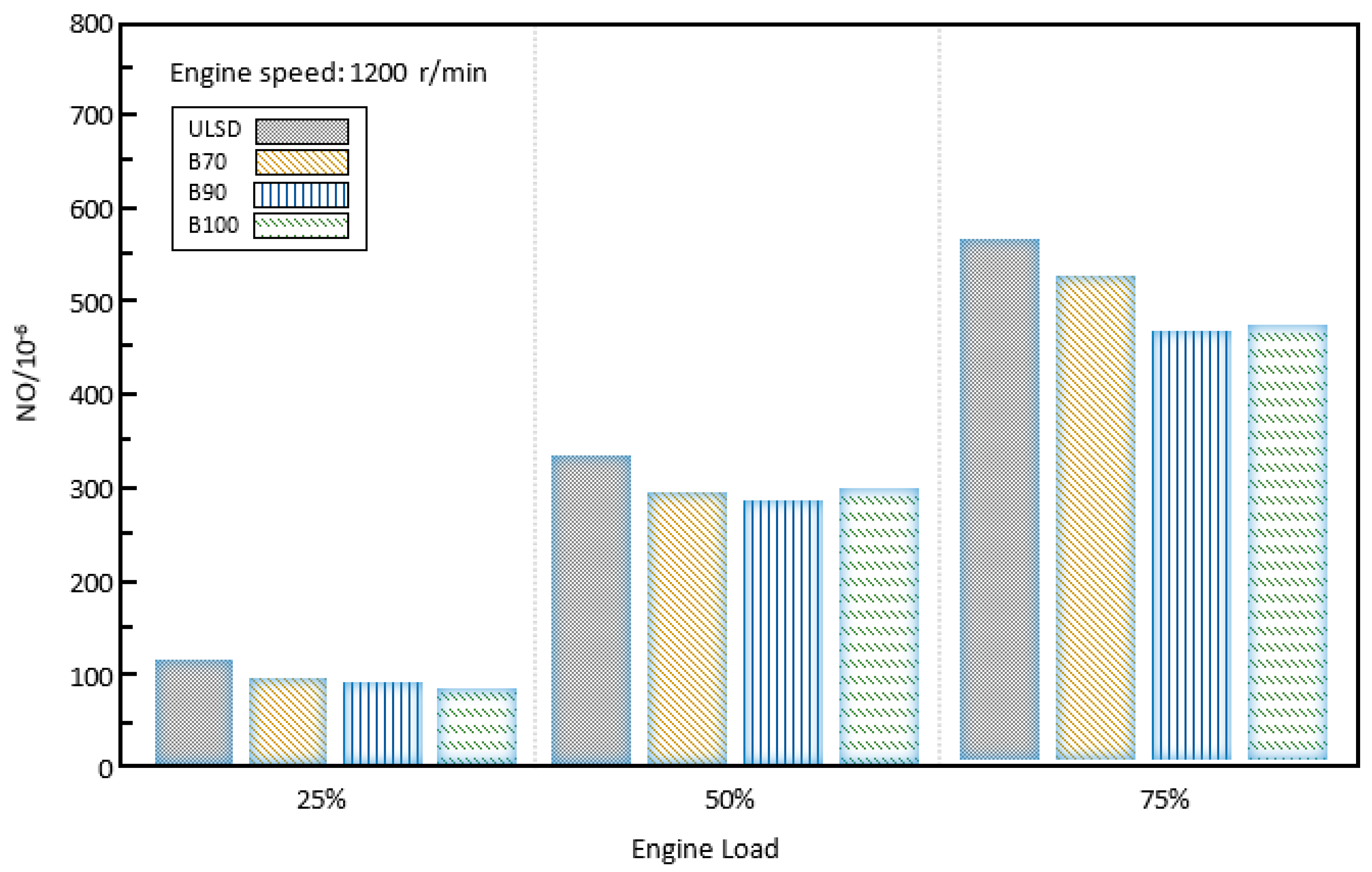
4.4. Tested Engine’s NO and NO2 Emissions with Different Tested Fuels
The various fuel mixture influences on the NO and NO
2 emissions are shown in
Figure 12 and
Figure 13. Emissions of NOx rise with increasing engine speed and load, but with the biodiesel addition to the fuel mixture, these emissions can be reduced. A higher amount of biodiesel in the test fuel mixture reduces NO
2 emissions with increasing engine load.
5. Conclusions
The goal of this article is to examine the influence of various fuel mixtures in a marine ancillary diesel engine on the formation of NO and NO2 emissions and ignition characteristics. A 6 L, turbocharged diesel engine with direct fuel injection was used to perform the experiments. Testing fuels were produced by mixing ULSD-F and biodiesel with ratios of 0, 50, 80, and 100%. Mixed fuels were marked as B0:U100, B50:U50, B80:U20, and B100:U0. The first fuel to be tested was pure ULSD-F, while the last fuel tested was pure biodiesel. The experiment was carried out at engine speeds of 1200 and 1440 rpm, with engine loads ranging from 10 to 80%. Data acquired from individual measurements serve as outputs that can be summarised into the following knowledge:
A higher biodiesel amount in the tested mixture increases in-cylinder pressure moderately while heat generation speed is significantly reduced;
A higher biodiesel amount in the tested mixture shortens the ignition delay and increases combustion speed. The ignition delay was shortened by about 2° CA;
As is obvious, rising engine speed and engine loads increase the formation of NOx emissions, but a higher biodiesel amount in tested fuel can significantly reduce formed NOx emissions;
With rising engine loads, NO emissions increase, but a higher amount of biodiesel can keep them lower. A noticeably reduced amount of NO2 emissions occurs with the increasing amount of biodiesel in the experimental fuel.
Author Contributions
Conceptualization, M.P.; methodology, M.P. and P.T.; investigation, M.P. and P.T.; data analysis, P.T. and M.L.; writing—original draft preparation, M.L. and M.Š.; writing—review and editing, M.Š. All authors have read and agreed to the published version of the manuscript.
Funding
This work was supported by the Slovak Research and Development Agency under Contract no. APVV-19-0328. The article was written in the framework of Grant Projects: VEGA 1/0318/21 “Research and development of innovations for more efficient utilization of renewable energy sources and for reduction of the carbon footprint of vehicles” and KEGA 006TUKE-4/2020 “Implementation of Knowledge from Research Focused on Reduction of Motor Vehicle Emissions into the Educational Process”.
Institutional Review Board Statement
Not applicable.
Informed Consent Statement
Not applicable.
Data Availability Statement
Not applicable.
Conflicts of Interest
The authors declare no conflict of interest.
References
- Florea, R.; Zha, K.; Yu, X.; Jansons, M.; Taraza, D.; Henein, N. Ethanol/N-Heptane Dual-Fuel Partially Premixed Combustion Analysis through Formaldehyde PLIF. SAE Int. J. Engines 2012, 5, 483–492. [Google Scholar] [CrossRef]
- Hanson, R.; Kokjohn, S.; Splitter, D.; Reitz, R. An Experimental Investigation of Fuel Reactivity Controlled PCCI Combustion in a Heavy-Duty Engine. SAE Int. J. Engines 2010, 3, 700–716. [Google Scholar] [CrossRef]
- Li, J.; Yang, W.; An, H.; Zhao, D. Effects of fuel ratio and injection timing on gasoline/biodiesel fueled RCCI engine: A modeling study. Appl. Energy 2015, 155, 59–67. [Google Scholar] [CrossRef]
- Hanson, R.; Curran, S.; Wagner, R.; Kokjohn, S.; Splitter, D.; Reitz, R. Piston Bowl Optimization for RCCI Combustion in a Light-Duty Multi-Cylinder Engine. SAE Int. J. Engines 2012, 5, 286–299. [Google Scholar] [CrossRef]
- Zhou, D.; Yang, W.; Li, J.; Tay, K.; Kraft, M. Combustion modeling in RCCI engines with a hybrid characteristic time combustion and closed reactor model. Appl. Energy 2018, 227, 665–671. [Google Scholar] [CrossRef]
- Benajes, J.; Molina, S.; García, A.; Belarte, E.; Vanvolsem, M. An investigation on RCCI combustion in a heavy duty diesel engine using in-cylinder blending of diesel and gasoline fuels. Appl. Therm. Eng. 2014, 63, 66–76. [Google Scholar] [CrossRef]
- Nieman, D.; Dempsey, A.; Reitz, R. Heavy-Duty RCCI Operation Using Natural Gas and Diesel. SAE Int. J. Engines 2012, 5, 270–285. [Google Scholar] [CrossRef]
- Kakaee, A.; Rahnama, P.; Paykani, A. Influence of fuel composition on combustion and emissions characteristics of natural gas/diesel RCCI engine. J. Nat. Gas Sci. Eng. 2015, 25, 58–65. [Google Scholar] [CrossRef]
- Jia, Z.; Denbratt, I. Experimental Investigation of Natural Gas-Diesel Dual-Fuel RCCI in a Heavy-Duty Engine. SAE Int. J. Engines 2015, 8, 797–807. [Google Scholar] [CrossRef]
- Ryan Walker, N.; Wissink, M.; DelVescovo, D.; Reitz, R. Natural Gas for High Load Dual-Fuel Reactivity Controlled Compression Ignition in Heavy-Duty Engines. J. Energy Resour. Technol. 2015, 137, 042202. [Google Scholar] [CrossRef]
- Puskar, M.; Kopas, M.; Soltesova, M.; Tarbajovsky, P. Simulation model of advanced system for application of sustainable fuels. Int. J. Simul. Model. 2022, 21, 308–319. [Google Scholar] [CrossRef]
- Li, Y.; Jia, M.; Chang, Y.; Liu, Y.; Xie, M.; Wang, T.; Zhou, L. Parametric study and optimization of a RCCI (reactivity controlled compression ignition) engine fuelled with methanol and diesel. Energy 2014, 65, 319–332. [Google Scholar] [CrossRef]
- Puškár, M.; Živčák, J.; Kočišová, M.; Šoltésová, M.; Kopas, M. Impact of bio-renewable energy sources on reduction of emission footprint from vehicles. Biofuels Bioprod. Biorefining 2021, 15, 1385–1394. [Google Scholar] [CrossRef]
- Yin, Z.; Linga, P. Methane hydrates: A future Clean Energy Resource. Chin. J. Chem. Eng. 2019, 27, 2026–2036. [Google Scholar] [CrossRef]
- Zang, R.; Yao, C. Numerical Study of Combustion and Emission Characteristics of a Diesel/Methanol Dual Fuel (DMDF) Engine. Energy Fuels 2015, 29, 3963–3971. [Google Scholar] [CrossRef]
- Kousheshi, N.; Yari, M.; Paykani, A.; Saberi Mehr, A.; de la Fuente, G. Effect of Syngas Composition on the Combustion and Emissions Characteristics of a Syngas/Diesel RCCI Engine. Energies 2020, 13, 212. [Google Scholar] [CrossRef]
- Kuric, I.; Tlach, V.; Císar, M.; Ságová, Z.; Zajačko, I. Examination of industrial robot performance parameters utilizing machine tool diagnostic methods. Int. J. Adv. Robot. Syst. 2020, 17, 172988142090572. [Google Scholar] [CrossRef]
- Han, X.; Divekar, P.; Reader, G.; Zheng, M.; Tjong, J. Active Injection Control for Enabling Clean Combustion in Ethanol-Diesel Dual-Fuel Mode. SAE Int. J. Engines 2015, 8, 890–902. [Google Scholar] [CrossRef]
- Fang, W.; Fang, J.; Kittelson, D.; Northrop, W. An Experimental Investigation of Reactivity-Controlled Compression Ignition Combustion in a Single-Cylinder Diesel Engine Using Hydrous Ethanol. J. Energy Resour. Technol. 2014, 137, 031101. [Google Scholar] [CrossRef]
- Wang, H.; DelVescovo, D.; Yao, M.; Reitz, R. Numerical Study of RCCI and HCCI Combustion Processes Using Gasoline, Diesel, iso-Butanol and DTBP Cetane Improver. SAE Int. J. Engines 2015, 8, 831–845. [Google Scholar] [CrossRef]
- Dempsey, A.; Walker, N.; Reitz, R. Effect of Piston Bowl Geometry on Dual Fuel Reactivity Controlled Compression Ignition (RCCI) in a Light-Duty Engine Operated with Gasoline/Diesel and Methanol/Diesel. SAE Int. J. Engines 2013, 6, 78–100. [Google Scholar] [CrossRef]
- Benajes, J.; Molina, S.; García, A.; Monsalve-Serrano, J. Effects of direct injection timing and blending ratio on RCCI combustion with different low reactivity fuels. Energy Convers. Manag. 2015, 99, 193–209. [Google Scholar] [CrossRef]
- Pavlenko, I.; Ivanov, V.; Kuric, I.; Gusak, O.; Liaposhchenko, O. Ensuring vibration reliability of turbopump units using Artificial Neural Networks. Lect. Notes Mech. Eng. 2019, 165–175. [Google Scholar] [CrossRef]
- Zhou, D.; Yang, W.; An, H.; Li, J. Application of CFD-chemical kinetics approach in detecting RCCI engine knocking fuelled with biodiesel/methanol. Appl. Energy 2015, 145, 255–264. [Google Scholar] [CrossRef]
- Lapuerta, M.; Rodríguez-Fernández, J.; Oliva, F.; Canoira, L. Biodiesel from Low-Grade Animal Fats: Diesel Engine Performance and Emissions. Energy Fuels 2008, 23, 121–129. [Google Scholar] [CrossRef]
- Vallinayagam, R.; Vedharaj, S.; Yang, W.; Lee, P.; Chua, K.; Chou, S. Combustion performance and emission characteristics study of pine oil in a diesel engine. Energy 2013, 57, 344–351. [Google Scholar] [CrossRef]
- Vedharaj, S.; Vallinayagam, R.; Yang, W.; Chou, S.; Chua, K.; Lee, P. Experimental investigation of kapok (Ceiba pentandra) oil biodiesel as an alternate fuel for diesel engine. Energy Convers. Manag. 2013, 75, 773–779. [Google Scholar] [CrossRef]
- Píštěk, V.; Klimeš, L.; Mauder, T.; Kučera, P. Optimal design of structure in rheological models: An automotive ap-plication to dampers with high viscosity silicone fluids. J. Vibroeng. 2017, 19, 4459–4470. [Google Scholar] [CrossRef][Green Version]
- Min, K.; Valco, D.J.; Oldani, A.; Kim, K.; Temme, J.; Kweon, C.-B.M.; Lee, T. Autoignition of varied cetane number fuels at low temperatures. Proc. Combust. Inst. 2019, 37, 5003–5011. [Google Scholar] [CrossRef]
- Splitter, D.; Kokjohn, S.; Rein, K.; Hanson, R.; Sanders, S.; Reitz, R. An Optical Investigation of Ignition Processes in Fuel Reactivity Controlled PCCI Combustion. SAE Int. J. Engines 2010, 3, 142–162. [Google Scholar] [CrossRef]
- Kokjohn, S.; Reitz, R.; Splitter, D.; Musculus, M. Investigation of Fuel Reactivity Stratification for Controlling PCI Heat-Release Rates Using High-Speed Chemiluminescence Imaging and Fuel Tracer Fluorescence. SAE Int. J. Engines 2012, 5, 248–269. [Google Scholar] [CrossRef]
- Lamas Galdo, M.I.; Castro-Santos, L.; Rodriguez Vidal, C.G. Numerical analysis of NOx reduction using ammonia injection and comparison with water injection. J. Mar. Sci. Eng. 2020, 8, 109. [Google Scholar] [CrossRef]
- Ojstersek, R.; Acko, B.; Buchmeister, B. Simulation study of a flexible manufacturing system regarding sustainability. Int. J. Simul. Model. 2020, 19, 65–76. [Google Scholar] [CrossRef]
- Puškár, M.; Kopas, M.; Sabadka, D.; Kliment, M.; Šoltésová, M. Reduction of the gaseous emissions in the marine diesel engine using biodiesel mixtures. J. Mar. Sci. Eng. 2020, 8, 330. [Google Scholar] [CrossRef]
- Puškár, M.; Živčák, J.; Tarbajovský, P. Complex analysis of combustion and emission parameters of bio-renewable fuel mixtures in dual-fuel mode. Biofuels Bioprod. Biorefining 2022, 16, 1744–1760. [Google Scholar] [CrossRef]
- Maláková, S.; Puškár, M.; Frankovský, P.; Sivák, S.; Palko, M.; Palko, M. Meshing stiffness—a parameter affecting the emission of gearboxes. Appl. Sci. 2020, 10, 8678. [Google Scholar] [CrossRef]
- Hudák, R.; Schnitzer, M.; Králová, Z.O.; Gorejová, R.; Mitrík, L.; Rajťúková, V.; Tóth, T.; Kovačević, M.; Riznič, M.; Oriňaková, R.; et al. Additive Manufacturing of porous ti6al4v alloy: Geometry Analysis and mechanical properties testing. Appl. Sci. 2021, 11, 2611. [Google Scholar] [CrossRef]
- Xue, J.; Grift, T.; Hansen, A. Effect of biodiesel on engine performances and emissions. Renew. Sustain. Energy Rev. 2011, 15, 1098–1116. [Google Scholar] [CrossRef]
- Kuric, I.; Kandera, M.; Klarák, J.; Ivanov, V.; Więcek, D. Visual product inspection based on Deep Learning Methods. Lect. Notes Mech. Eng. 2020, 148–156. [Google Scholar] [CrossRef]
- An, H.; Yang, W.; Chou, S.; Chua, K. Combustion and emissions characteristics of diesel engine fueled by biodiesel at partial load conditions. Appl. Energy 2012, 99, 363–371. [Google Scholar] [CrossRef]
- An, H.; Yang, W.; Maghbouli, A.; Li, J.; Chou, S.; Chua, K. Performance, combustion and emission characteristics of biodiesel derived from waste cooking oils. Appl. Energy 2013, 112, 493–499. [Google Scholar] [CrossRef]
- Li, J.; Yang, W.; An, H.; Maghbouli, A.; Chou, S. Effects of piston bowl geometry on combustion and emission characteristics of biodiesel fueled diesel engines. Fuel 2014, 120, 66–73. [Google Scholar] [CrossRef]
- Puškár, M.; Fabian, M.; Kádárová, J.; Blišt’an, P.; Kopas, M. Autonomous vehicle with internal combustion drive based on the homogeneous charge compression ignition technology. Int. J. Adv. Robot. Syst. 2017, 14, 172988141773689. [Google Scholar] [CrossRef]
- Pal, S.; Gubeljak, N.; Bončina, T.; Hudák, R.; Toth, T.; Zivcak, J.; Lojen, G.; Leben, N.; Drstvenšek, I. The effects of locations on the build tray on the quality of specimens in powder bed additive manufacturing. Int. J. Adv. Manuf. Technol. 2021, 112, 1159–1170. [Google Scholar] [CrossRef]
Figure 1.
Tested engine scheme.
Figure 1.
Tested engine scheme.
Figure 2.
Tested fuels’ influence on the heat release rate and cylinder pressure at 1200 rpm and 30% load.
Figure 2.
Tested fuels’ influence on the heat release rate and cylinder pressure at 1200 rpm and 30% load.
Figure 3.
Tested fuels’ influence on the heat release rate and cylinder pressure at 1200 rpm and 60% load.
Figure 3.
Tested fuels’ influence on the heat release rate and cylinder pressure at 1200 rpm and 60% load.
Figure 4.
Tested fuels’ influence on the heat release rate and cylinder pressure at 1200 rpm and 90% load.
Figure 4.
Tested fuels’ influence on the heat release rate and cylinder pressure at 1200 rpm and 90% load.
Figure 5.
Tested fuels’ influence on the heat release rate and cylinder pressure at 1440 rpm and 30% load.
Figure 5.
Tested fuels’ influence on the heat release rate and cylinder pressure at 1440 rpm and 30% load.
Figure 6.
Tested fuels’ influence on the heat release rate and cylinder pressure at 1440 rpm and 60% load.
Figure 6.
Tested fuels’ influence on the heat release rate and cylinder pressure at 1440 rpm and 60% load.
Figure 7.
Tested fuels’ influence on the heat release rate and cylinder pressure at 1200 rpm and 30% load.
Figure 7.
Tested fuels’ influence on the heat release rate and cylinder pressure at 1200 rpm and 30% load.
Figure 8.
Tested fuels’ influence on the exhaust gas temperature at 1200 rpm.
Figure 8.
Tested fuels’ influence on the exhaust gas temperature at 1200 rpm.
Figure 9.
Tested fuels’ influence on the exhaust gas temperature at 1200 rpm.
Figure 9.
Tested fuels’ influence on the exhaust gas temperature at 1200 rpm.
Figure 10.
Tested fuels’ influence on the exhaust gas temperature at 1200 rpm.
Figure 10.
Tested fuels’ influence on the exhaust gas temperature at 1200 rpm.
Figure 11.
Tested fuels’ influence on the exhaust gas temperature at 1200 rpm.
Figure 11.
Tested fuels’ influence on the exhaust gas temperature at 1200 rpm.
Figure 12.
Tested fuels’ influence on the exhaust gas temperature at 1200 rpm.
Figure 12.
Tested fuels’ influence on the exhaust gas temperature at 1200 rpm.
Figure 13.
Tested fuels’ influence on the exhaust gas temperature at 1200 rpm.
Figure 13.
Tested fuels’ influence on the exhaust gas temperature at 1200 rpm.
Table 1.
NOx emission standards for marine engines.
Table 1.
NOx emission standards for marine engines.
| Tier | Date of Ship Construction (on or after) | Total Weighted Cycle Emissions Limit (g/kWh)
n = rpm (Engine Rate Speed) |
|---|
| n < 130 | n = 130–1999 | n ≥ 2000 |
|---|
| I | 1 January 2000 | 17.0 | 45 n(−0.2)
e.g., 720 rpm–12.1 | 9.8 |
| II | 1 January 2011 | 14.4 | 45 n(−0.2)
e.g., 720 rpm–9.7 | 7.7 |
| III | 1 January 2016 | 3.4 | 9 n(−0.2)
e.g., 720 rpm–2.4 | 1.96 |
Table 2.
Sulphur limits for marine engine fuel oil.
Table 2.
Sulphur limits for marine engine fuel oil.
| Date | Sulphur Limit in Fuel (% m/m) |
|---|
| Sox ECA | Global |
|---|
| 2000 | 1.5% | 4.5% |
| July 2010 | 1.0% |
| 2012 | 3.5% |
| 2015 | 0.1% |
| 2020 | 0.5% |
Table 3.
Biodiesel and ULSD-F specifications.
Table 3.
Biodiesel and ULSD-F specifications.
| Specification | Bio-Diesel | ULSD-F |
|---|
| Density [kg/m3] | (860, 900) | (810, 850) |
| Viscosity [mm2/s] | (3.5, 5.0) | (2.0, 4.0) |
| Cetane number | 51 | 48 |
| Flashpoint [°C] | 101 | 82 |
| Carbon content [%] | 81.5 | 97.1 |
Table 4.
Various test fuel mixtures’ fuel consumption at different engine loads and engine speeds.
Table 4.
Various test fuel mixtures’ fuel consumption at different engine loads and engine speeds.
| Engine Speed | Engine Loading | ULSD-F | B50:U50 | B80:U20 | Biodiesel |
|---|
| FC [kg/h] | FC [kg/h] | FC [kg/h] | FC [kg/h] |
|---|
| 1200 rpm | 214 Nm (30%) | 9.54 | 10.28 | 10.57 | 10.68 |
| 427 Nm (60%) | 16.04 | 17.48 | 17.84 | 18.11 |
| 641 Nm (90%) | 21.74 | 23.53 | 24.25 | 24.43 |
| 1440 rpm | 257 Nm (30%) | 11.47 | 12.36 | 12.67 | 12.83 |
| 514 Nm (60%) | 18.59 | 21.02 | 21.45 | 21.78 |
| 770 Nm (90%) | 26.13 | 28.29 | 29.16 | 29.25 |
Table 5.
Measuring device technical data.
Table 5.
Measuring device technical data.
| | Measurement Range | Tolerance |
|---|
| °C, exhaust gas | −40–1000 °C | Max. ±5 K |
| O2 | 0–25 Vol.% | According to MARPOL Annex VI and the NOx Technical Code |
| CO | 0–3000 ppm |
| NO | 0–3000 ppm |
| NO2 | 0–500 ppm |
| SO2 | 0–3000 ppm |
| CO2 (IR) | 0–40 Vol.% | ±5 hPa at +22 °C |
| Pabs | 600–1150 hPa | ±10 hPa at −5–45 °C |
| Publisher’s Note: MDPI stays neutral with regard to jurisdictional claims in published maps and institutional affiliations. |
© 2022 by the authors. Licensee MDPI, Basel, Switzerland. This article is an open access article distributed under the terms and conditions of the Creative Commons Attribution (CC BY) license (https://creativecommons.org/licenses/by/4.0/).


