1. Introduction
In recent years, with the continuous development of unmanned driving, artificial intelligence, image processing, Internet space technology, etc., the whole industry has made great progress in digitalization and intelligence, and the USV is also rapidly developing towards intelligence [
1]. The research on USV has also become a research hotspot. USV has a wide application prospect [
2] because of its high flexibility and cost-effective characteristics, carrying specific equipment to complete a variety of dangerous specific tasks. In the military, the USV can be used for counter-reconnaissance and other intelligence collection, while in the civilian field, it can be used for water quality detection/monitoring, maritime patrol and ocean mapping [
3,
4,
5,
6]. To accomplish such missions, USVs require good motion control ability, and trajectory tracking control is the solution. Trajectory tracking is different from path tracking as for the former, the trajectory is parameterized and depends on time [
7], which requires the ship to reach specified coordinates along a specific trajectory at a specified time. The under-actuation of a USV increases the control difficulty because the number of independent control inputs is less than its degrees of freedom [
8] and is thus a nonlinear system [
9].
In practice, there are many factors in the system to deal with, such as nonlinearity, parameter uncertainty, unmeasurable noises, unmeasurable speeds and external environment disturbances, which bring great challenges to the design of the control system. A neural network can approximate any nonlinear function and can be used to solve the control problems in uncertain models. In [
10], the existing model uncertainties and external disturbances were treated by radial basis function neural network and disturbance observer, respectively. Similarly, neural network techniques and adaptive techniques were used to compensate for the uncertainty of the model [
11]. In [
12], a wavelet neural network was used to approximate completely unknown dynamic and external disturbances. In [
13], an adaptive neural network was proposed to approximate uncertain nonlinear dynamics and external environmental disturbances. Combined with the backstepping method, adaptive technology was used to approximate the disturbed boundary, and a neural network was used to approximate the uncertain function to achieve trajectory tracking [
14]. The difficulty of neural network radial basis function approximating arbitrary function lies in how to properly select the center points, the number of nodes and the appropriate width of radial basis function to generate hidden layers. Based on the stability theory of immersion and invariance, the asymptotic stability was guaranteed, and the adaptive law was derived to deal with the parameter uncertainty [
15]. An online constructive fuzzy approximator was designed to dynamically adjust fuzzy rules to deal with time-varying uncertainties [
16]. Combined with dynamic surface technology, the desired signal is smooth and bounded, and the control output realizes trajectory tracking.
In [
17], the external disturbances and model uncertainty were compensated by a disturbance observer, and trajectory tracking was realized by sliding mode control. A nonlinear disturbance observer was constructed to deal with the disturbances problem [
18]. For the unmeasured velocities problem, [
19] constructed a hyper-distortion observer to observe the velocity. The unknown disturbance is estimated by RBF neural network combined with adaptive method. In order to ensure sufficient safety, the state of the system is subject to certain boundary constraints to perform a specific task; Li et al. [
20] used the barrier Lyapunov function to constrain all states of the system to achieve trajectory tracking control. A pre-defined performance tracking control law based on quantization state was proposed to achieve tracking control without requiring system structural parameters and function approximators for a long time [
21]. In the trajectory tracking control of mobile robot [
22], state feedback control and disturbance feedforward compensation control are designed to solve the problems of unmeasurable speed and disturbance. Given that the disturbances are bounded, the disturbances suppression and tracking error reduction were guaranteed by finite time convergence.
Finite time control has better convergence performance and is more desirable in practical applications. It is able to complete the trajectory tracking task within finite time and has fast response characteristics [
23,
24,
25,
26,
27,
28]. Sliding mode control has been widely used in nonlinear uncertain systems because of its strong robustness, simple design and easy implementation. Traditional sliding mode control does not have the characteristics of finite time control. The terminal sliding mode can control the convergence rate near or away from the equilibrium point to realize finite time control because it introduces nonlinear function into sliding hyperplane design. It is widely used to solve finite time control problems [
29,
30,
31]. In [
32], a finite time adaptive sliding mode controller is designed, and the adaptive law is obtained by Lyapunov function. In [
33], a finite time control strategy is designed based on proportional integral-differential sliding mode control to make the error converge in finite time.
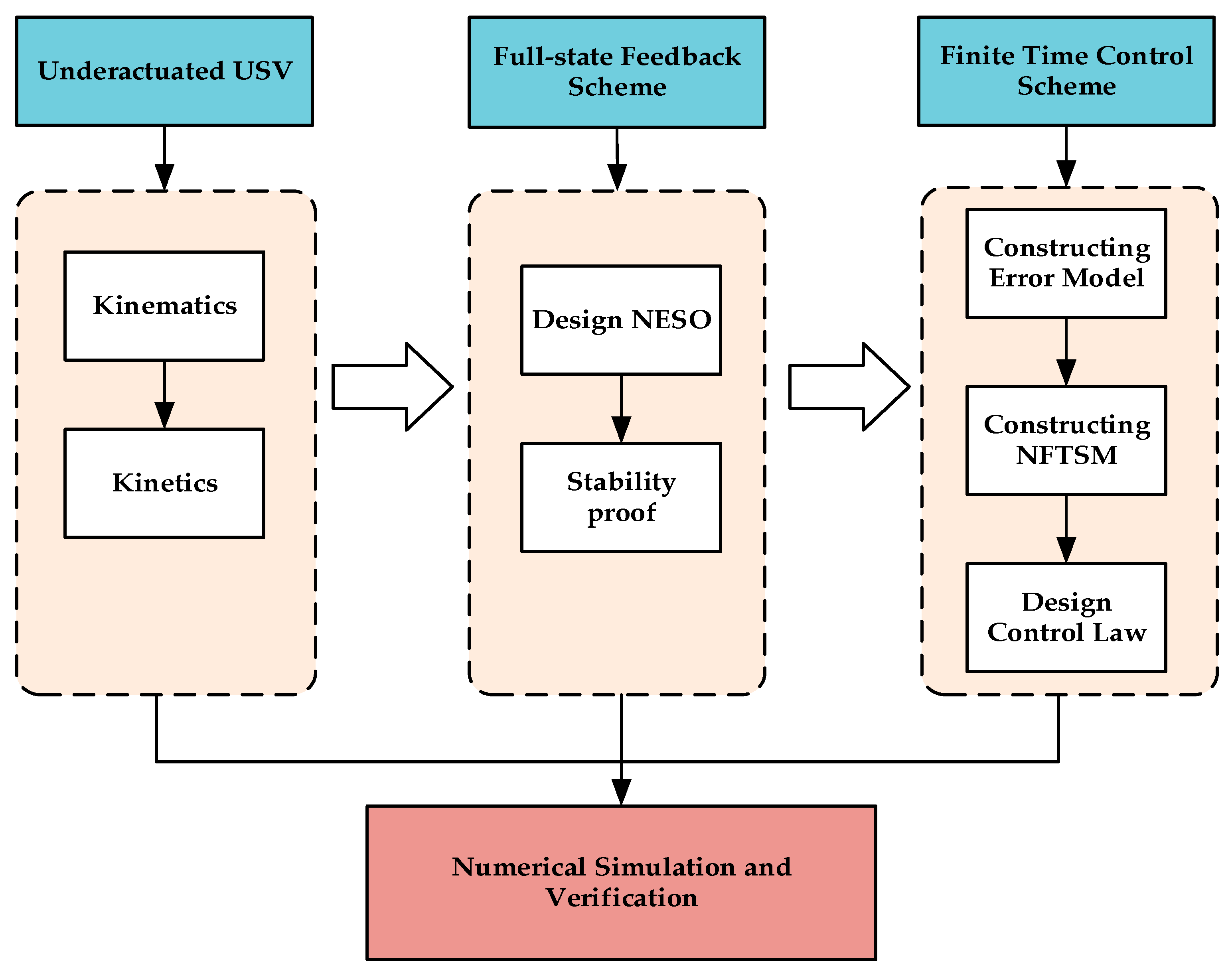
The above studies deal with the problems of external environmental disturbances by designing disturbance observers to compensate for the disturbance or neural network approximation and using state observers for velocity estimation. In this study, perturbation and velocity unmeasurable problems are considered and dealt with together. NESO and NFTSM are combined to realize finite time underactuated USV trajectory tracking control. The overall structure block diagram of this study is shown in
Figure 1. The underactuated USV mathematical model is taken as the research plant, and then NESO and NFTSM are designed and verified by numerical simulation. The main contributions are as follows:
A NESO is designed to achieve full-state feedback, which eliminates the need for a separate disturbance observer to compensate the disturbance, thus reducing the design difficulty. Uncertainty of model parameters and external disturbances are regarded as complex disturbances and expanded as part of the state variables of the system, and the observation values of complex disturbances feedback to the controller to simplify the design process. The observed values of velocity and position are obtained and feedback to the system, which is particularly useful in the case of sensor malfunction.
NFTSM can realize the convergence of tracking error in a shorter time, which is used to solve the problem of slow convergence of trajectory tracking error. According to Lyapunov stability theory, the corresponding surge force and yaw moment are derived to ensure the stability of the system. The numerical simulation by MATLAB verifies that the controller has fast response characteristics, and the chattering phenomenon of the controller is also reduced.
3. Underactuated USV Modeling and Problem Formulation
Assumption 1:Only three degrees of freedom of the underactuated USV are considered, namely, surge, sway and yaw.
Assumption 2:The underactuated USV has a uniform mass distribution and a left-right symmetry.
Assumption 3:The (Center of Gravity) CoG and Center of Buoyancy (COB) of the underactuated USV are located on the z-axis of the body-fixed coordinate system.
On the premise of the above assumptions, the kinematic and dynamic equations of USV can be obtained as follows:
where
denotes the actual positions and heading angle of underactuated USV in the Earth-fixed coordinate also called North-East-Down coordinate;
denotes the actual velocities and angle velocity;
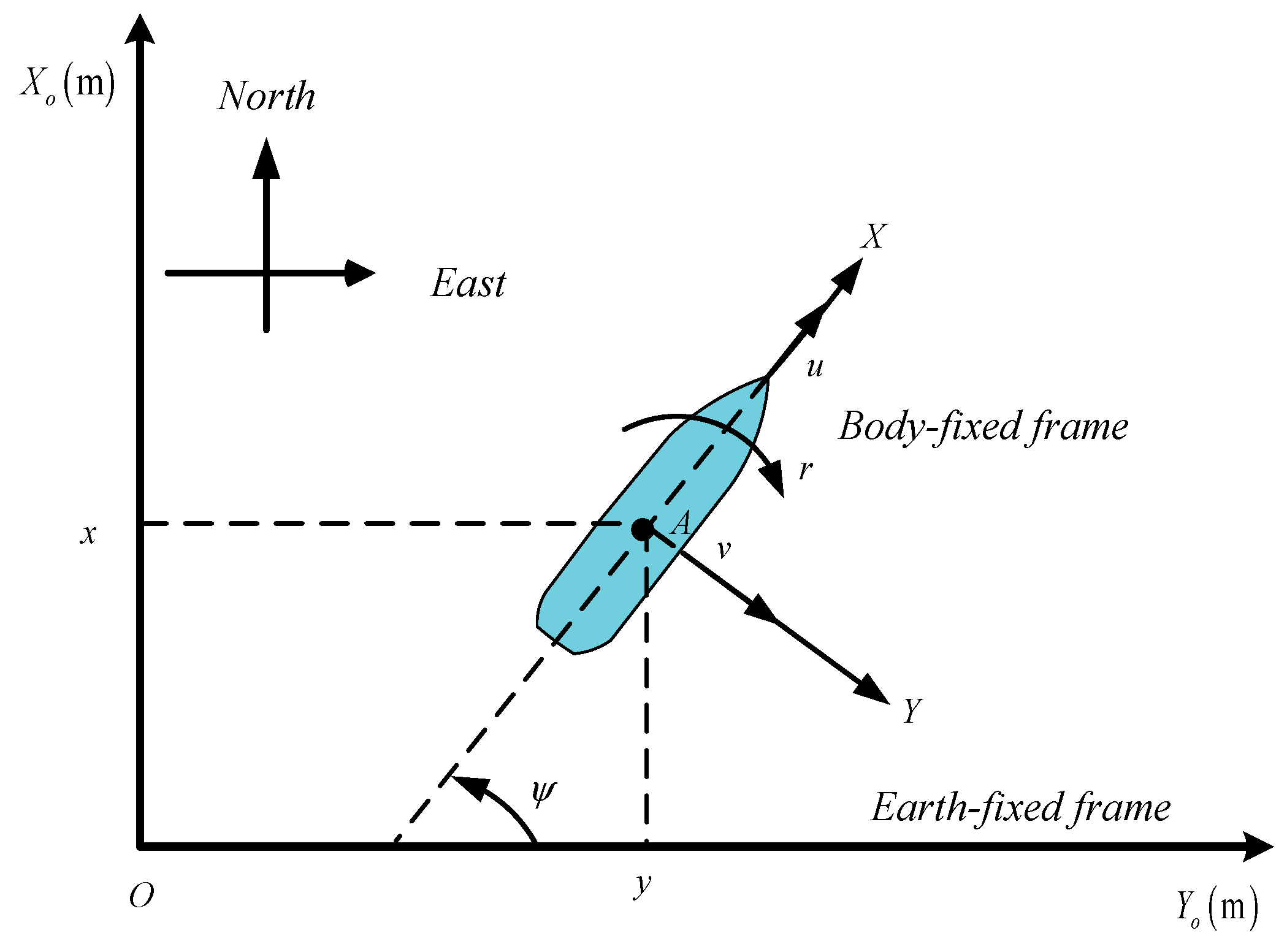
is the transformation matrix between the Earth-fixed coordinate system and the Body-fixed coordinate system, as shown in
Figure 2.
is inertial matrix;
is the Coriolis and centripetal matrix;
is the hydrodynamic damping parameters matrix;
denotes the surge force, sway force and yaw moment, where sway force is 0;
is used to represent the disturbances caused by the wind, wave and current environment of the USV. The above parameter matrices satisfy the following properties:
Property 1: The rotation matrix is orthogonal to satisfy
and
where
Property 2: The symmetric positive definite of the inertia matrix satisfies:
Property 3: The Coriolis and centripetal force matrices are obliquely symmetric and satisfy:
Property 4: Hydrodynamic damping matrix is an asymmetric and strictly positive definite real matrix, which satisfies:
The expressions of matrix
,
, and
are, respectively:
Define auxiliary quantity
, there are:
where
,
.
Therefore, the underactuated USV mathematical model can be written in the following form:
In this study, a reference trajectory is generated by providing a predefined input to the virtual underactuated USV, as shown in
Figure 3.
Similarly for virtual underactuated USV:
Defining an auxiliary quantity
, there are:
where
,
.
According to Equations (11) and (14), an error model can be obtained.
4. Design of NESO
In the actual navigation process, it is inevitable that the USV is subjected to the disturbances of the external environment: wind, wave and current. At the same time, considering the parameters perturbation, that is, the system inertia matrix, Coriolis centripetal force matrix and hydrodynamic damping matrix, this part of the influence will be regarded as whole complex disturbances, and it will be expanded into part of the system states to deal with together. Further considering the situation that the system states cannot be measured, NESO will be used to observe the system states, that is, the velocities, positions and composite disturbances are feedback to the underactuated USV system.
The following NESO can be designed for the underactuated USV model (12).
where
,
, the derivative of complex disturbances
is unknown but bounded, that is,
,
is position observed value of
,
is the observed value of
,
is complex disturbances observed value of
;
,
,
are gain matrix of NESO,
are the corresponding approximation errors. The function of
expression is as follow:
where
is independent variable of the function.
,
an arbitrary small positive number.
Combining Equations (12) and (16) to calculate the derivatives of
,
,
, the error system of NESO is as follows:
The error state equation of NESO can be expressed as:
where
The eigenequation of matrix
is
The characteristic polynomial of Equation (19) is
where
. Appropriate choice of parameter matrixes,
, makes
satisfy the Hurwitz stability condition. By Lyapunov’s second method, for arbitrary given positive definite matrix
and
, the following Lyapunov equation is satisfied.
Define the Lyapunov function regarding NESO as
The differential Equation (24) can be obtained.
When
, it can be proved that NESO is convergent, and the convergence conditions are:
From Equation (16), the observed value of position, the observed value of velocity, and the observed value of complex disturbance can be obtained. Using the observations obtained by NESO to replace the position states and velocity states corresponding to the actual USV, and the complex disturbances composed of unknown internal disturbances, namely model parameter disturbances and external unknown wind, wave and current environment disturbances, can simplify the design of the controller and reduce the complex operation process.
5. Controller Design
The feedback value of the underactuated USV system states obtained by NESO has been mentioned before. After redefining the error model, the sliding mode surface is designed for controller design. The control scheme structure diagram is shown in
Figure 4.
According to the design idea, the error model is redefined by the error model (15) and NESO (16).
From the definition of NFTSM, the following sliding surface can be obtained:
From Equations (27) and (28), the differential equation of the sliding mode surface can be obtained:
Since contains the required control , the Lyapunov function about the sliding surface is constructed, and the desired controller output can be obtained by selecting the appropriate to satisfy the Lyapunov stability condition.
Define the following Lyapunov function,
and obtain the differential equation:
If the underactuated USV input is selected as:
Substituting Equation (32) into Equation (31) can be obtained:
The Lyapunov function is selected, and the design makes , so it can be concluded that the underactuated USV system is stable.
6. Numerical Simulation and Analysis
In order to verify the effectiveness of using NESO for full-state feedback with the combination of NFTSM for finite-time trajectory tracking control, the BAYCLASS long-range patrol ship in reference [
35] is used for simulation, and the parameters of underactuated USV are shown in
Table 1. The virtual USV, actual USV, NESO and controller in the design process are modeled using the Simulink simulation tool in MATLAB, and the solver is chosen ode45 with variable step size. The work of the simulation is divided into two stages. First of all, the simulation verifies whether the mentioned NESO has a good approximation effect on the complex disturbances, positions and velocities state of the underactuated USV system. Finally, the simulation incorporates parameters perturbation using NESO to obtain the three-part state feedback values of positions, velocities, and expansion of the underactuated USV system combined with NFTSM to verify the simulation and compare it with the NTSM in [
36] in order to verify the design of the control.
The virtual underactuated USV used to generate the reference trajectory uses the same model parameters as the actual underactuated USV model. The initial values of position and velocity of underactuated USV are
and
. The initial values of positions and velocities of virtual underactuated USV are
and
. To reflect the parameter perturbation,
,
,
are used in the simulation. Four periods with higher probability of disturbance occurrence were chosen according to the scatter diagram of the sea states. The disturbances
caused by wind, wave and current are assumed to be:
where
,
, four different periods can be obtained when the angular frequency as
.
The reference trajectory is designed as the complex trajectory obtained by the combination of straight line and circle, and the control input
of the virtual underactuated USV is selected as follows:
The parameters selected for Equation (16) NESO are:
,
. Regarding the design form Equation (32) of the controller, the chosen parameters are
,
,
,
,
. It is worth noting that the symbolic function
in Equation (32) will cause obvious chattering in the controller in the actual simulation, so the saturation function is used to replace the symbolic function in the simulation, and the form of the saturation function is shown below.
The parameters used are , .
For the disturbances in the form of Equation (34), there are two different amplitudes. For the first amplitude, the disturbances as in Equation (37) are chosen for simulation.
Figure 5 shows the tracking curves of the complex disturbances
for four periods under the disturbances of Equation (37). The complex disturbances are related to the USV’s own velocity, position information and external environmental disturbances, which are non-periodic disturbances. The red curve, which is the observed value, is very close to the actual value (the blue curve), as can be seen in the figures below.
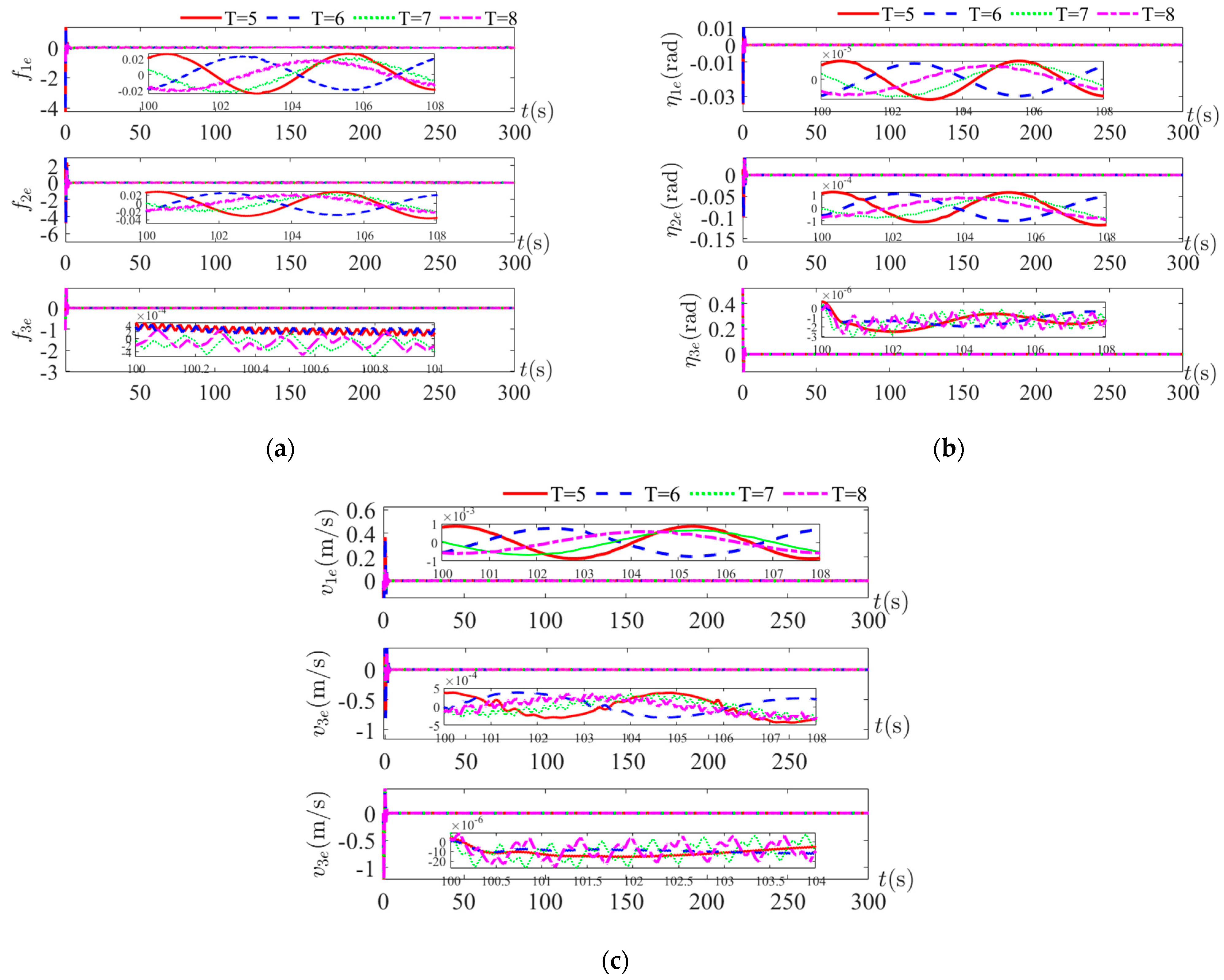
Figure 6 shows the observation error curves of complex disturbances
, positions
and velocities
. It can be seen in the three figures that for the three different state tracking error curves converge in a minimal neighborhood of zero. The composite disturbance error is less than
, and the position and velocity observation error is less than
. Despite the change in the period of the disturbance, the NESO observations are still valid within the error tolerance. There is an initial error in the estimation error of the vessel positions and velocities state at the initial stage. As time goes on, the error converges very quickly. From the convergence range of the error, it can be concluded that the estimated vessel speed and position states can replace the actual measured states information and feedback to the system. Therefore, when the states of the underactuated USV system cannot be measured or is disturbed by the external environment, the structural information of the system itself can be used to estimate the states information of the underactuated USV.
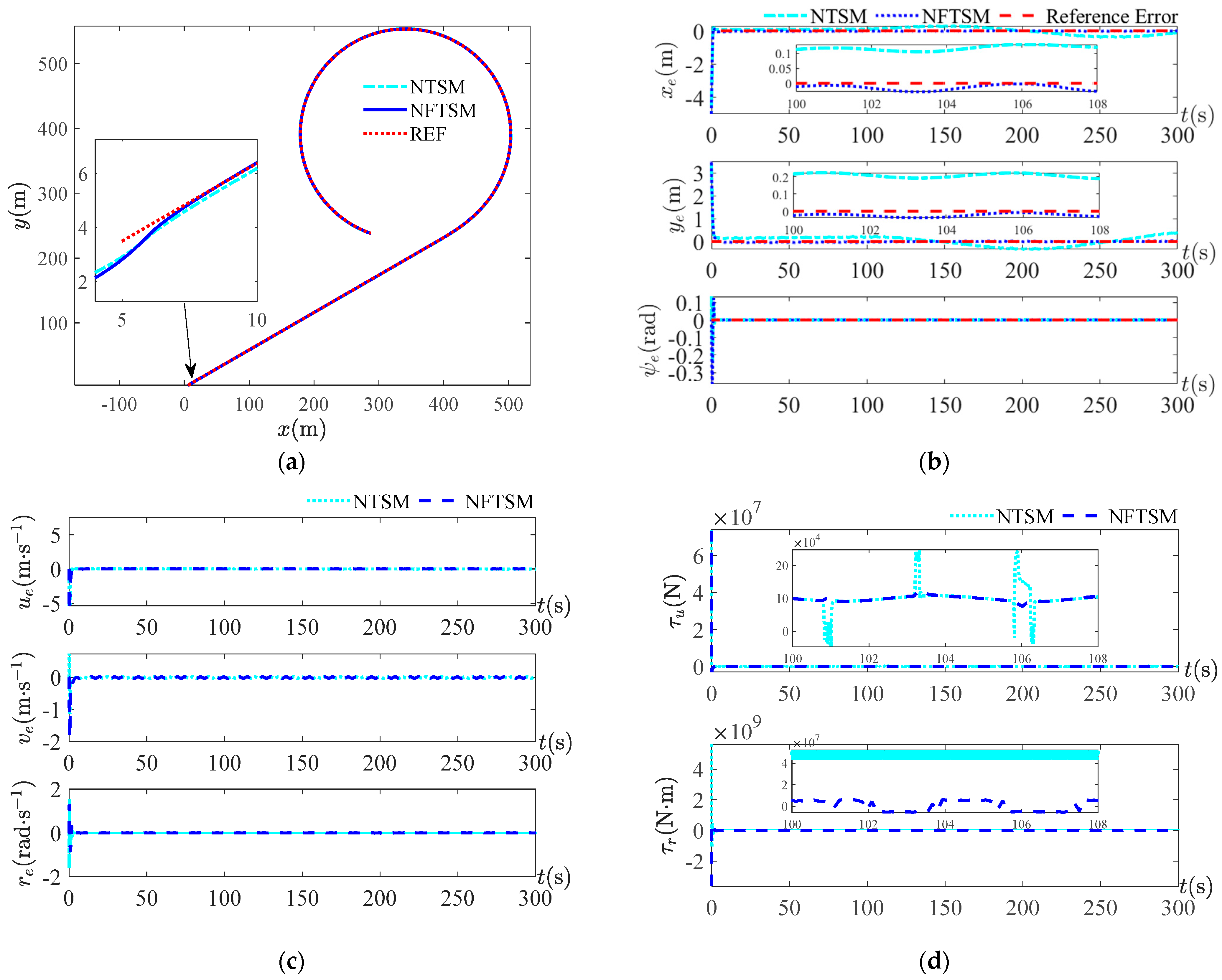
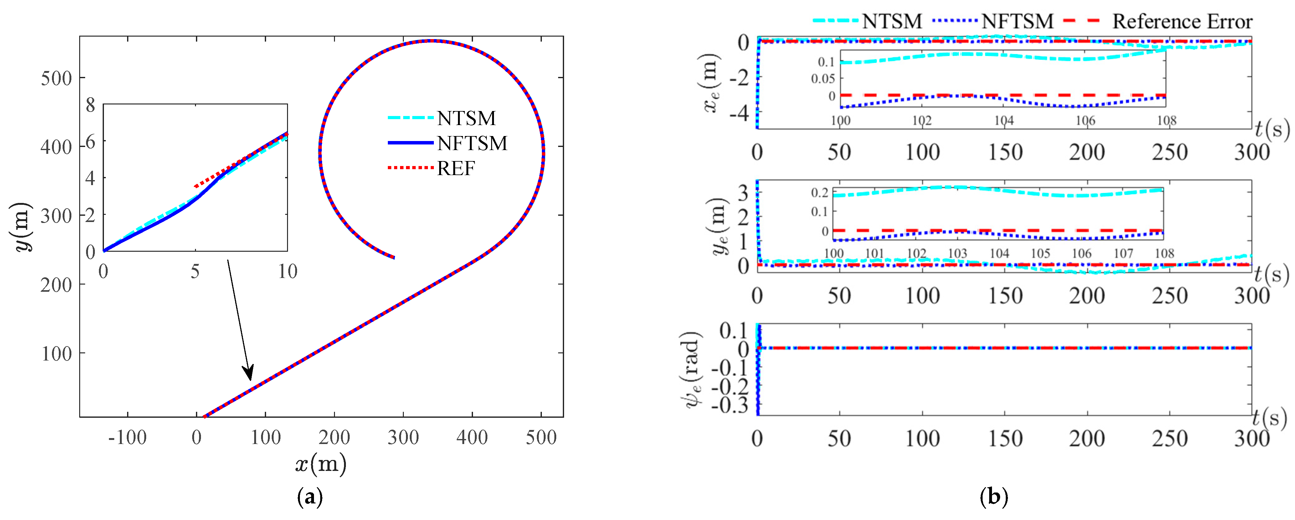
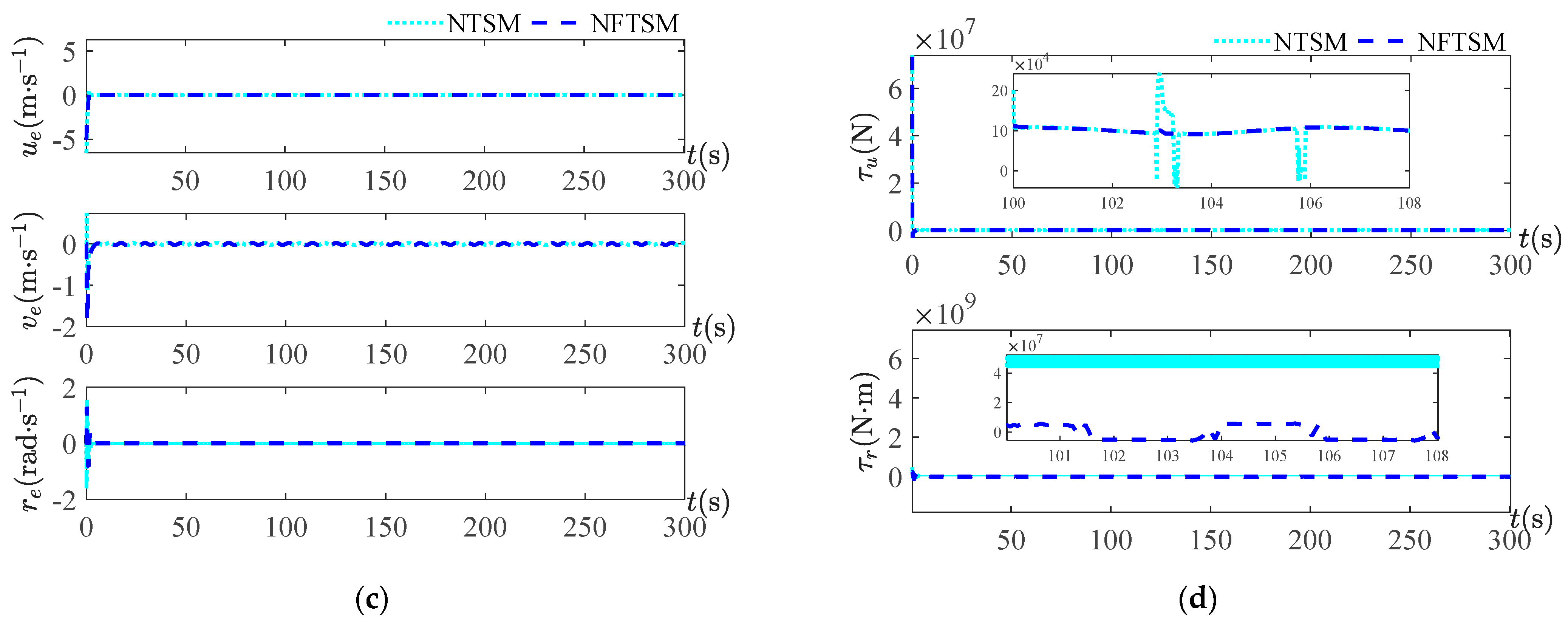
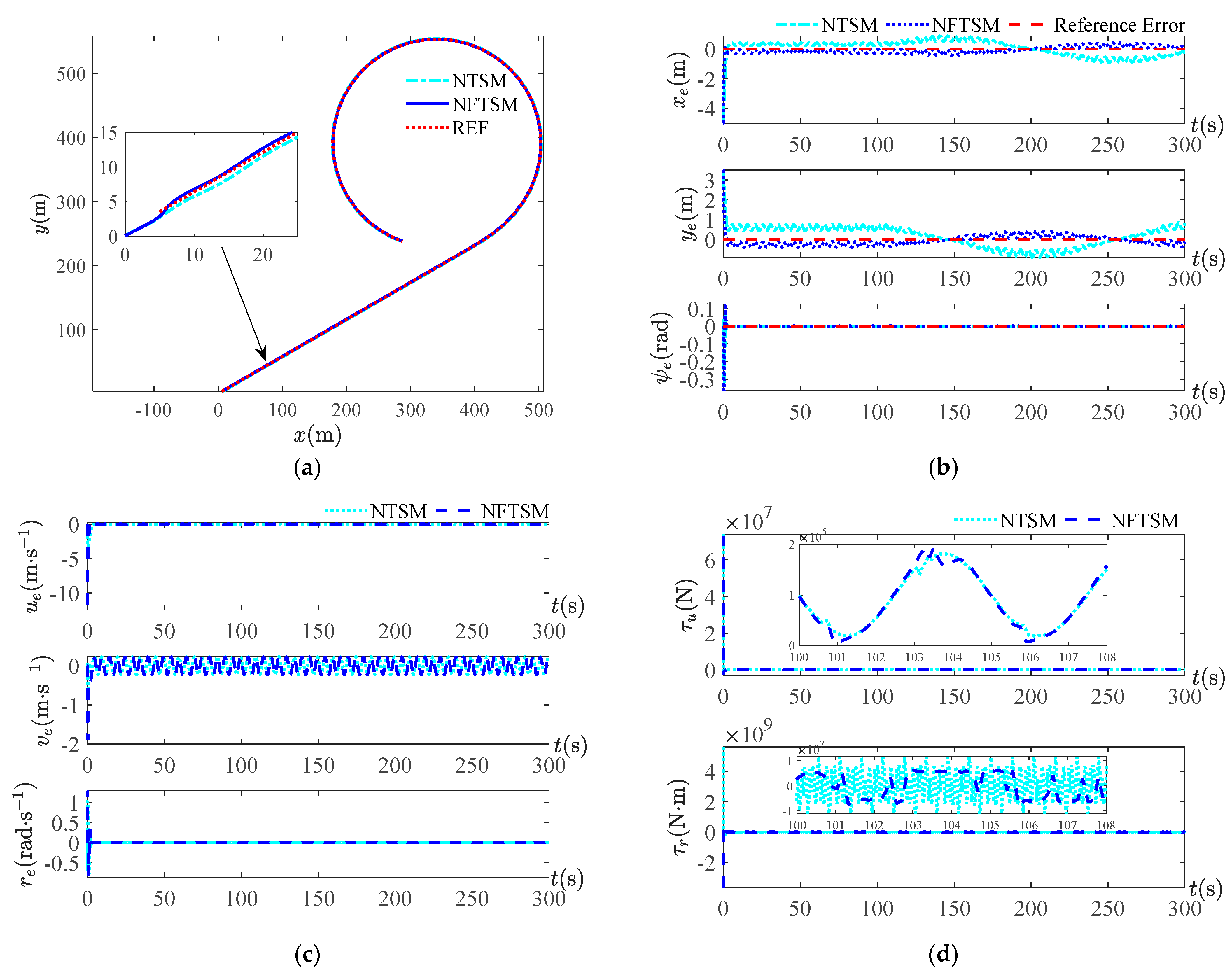
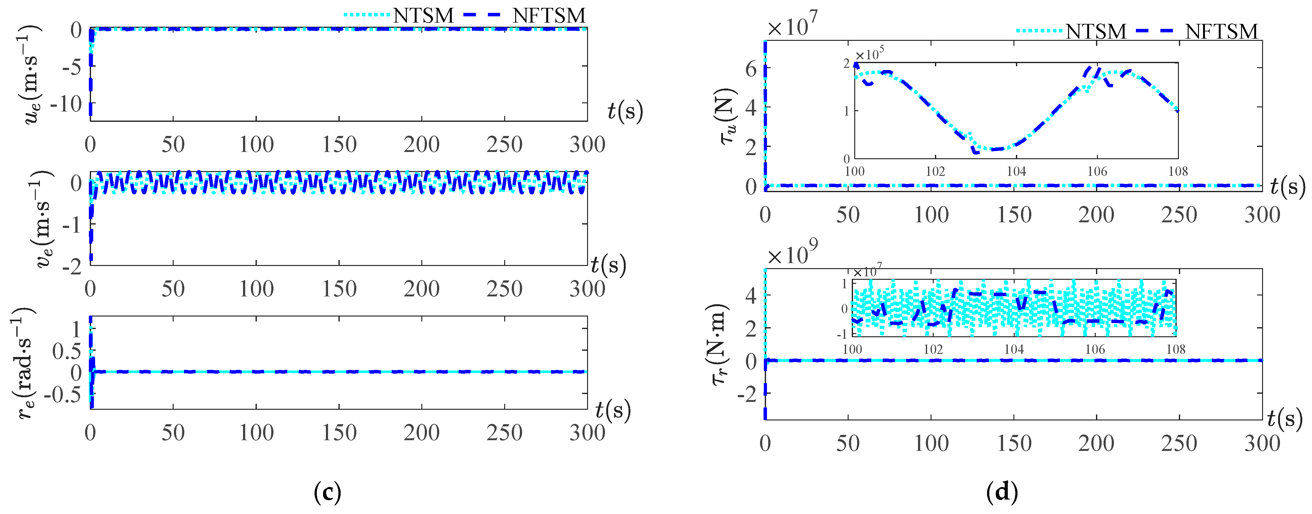
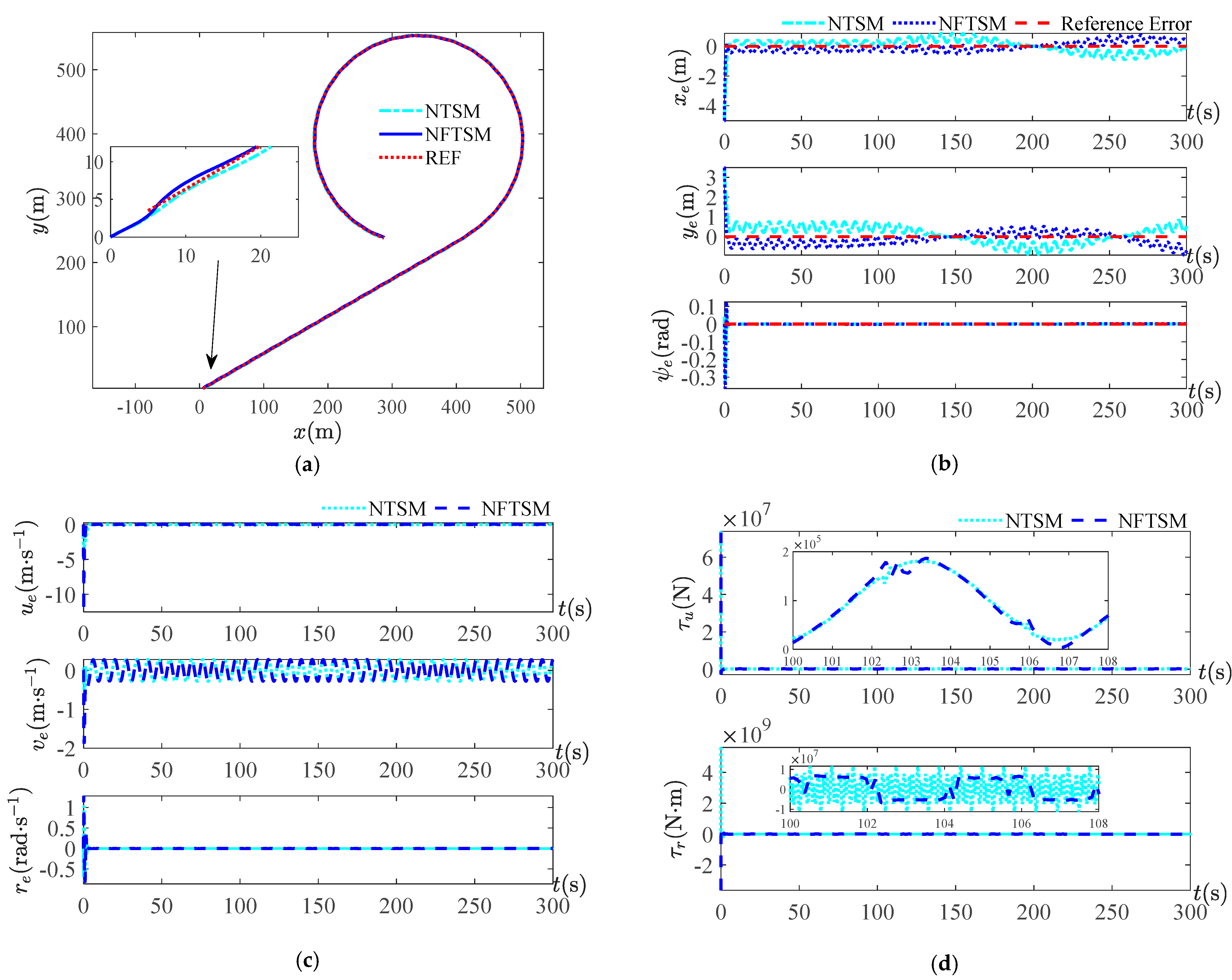
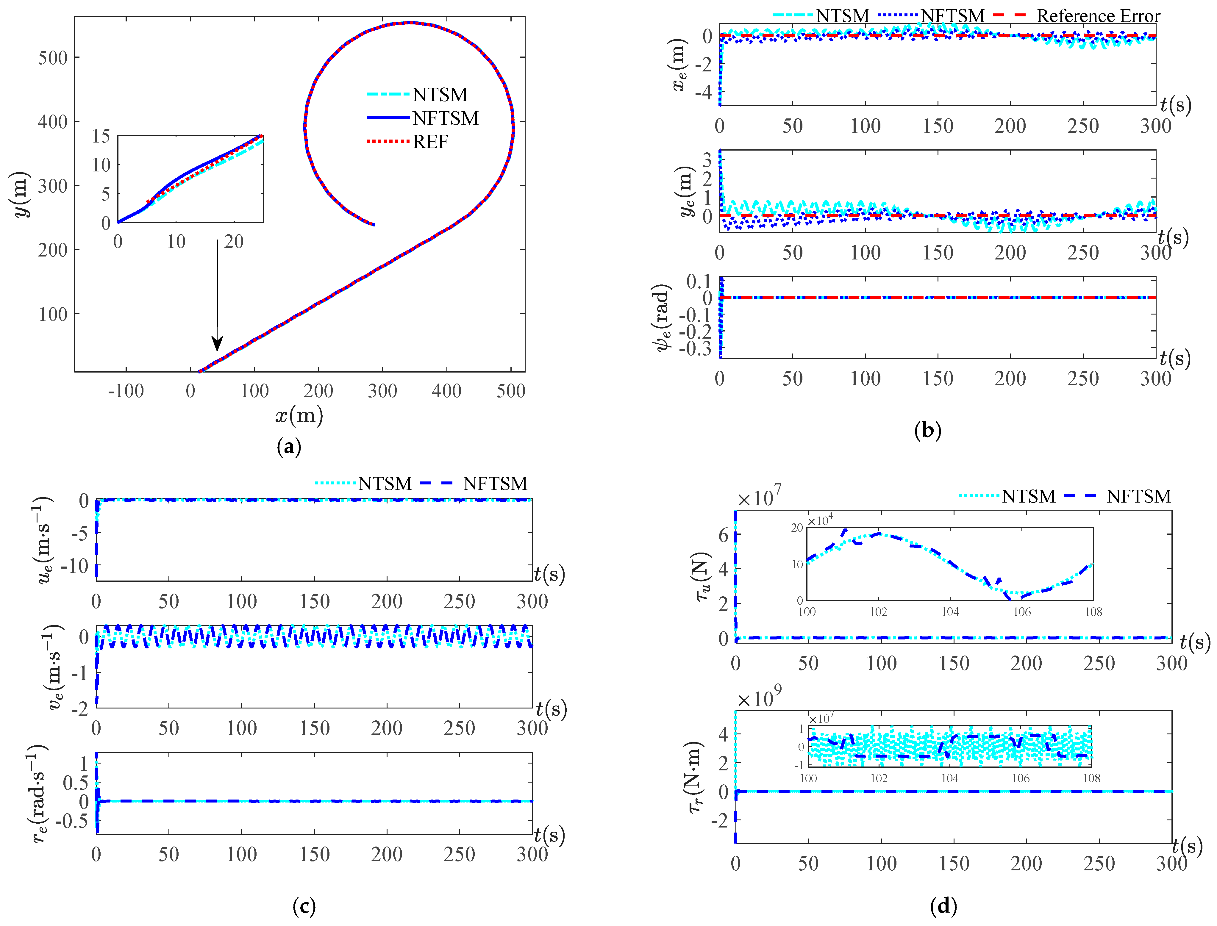
Figure 7,
Figure 8,
Figure 9 and
Figure 10 show the simulation results under four periods of disturbance
. The trajectory tracking curve, position tracking error curve, velocity tracking error curve and surge force and yaw moment curve are given for each period. For the trajectory tracking curves under four periods, it can be seen that, overall, both control methods can track the reference trajectory, but from the local zoom in, it can be seen that the NFTSM control method used in this study approaches the reference trajectory earlier than the NTSM method and the approximation error is smaller. The small error indicates that the safety is higher and the risk is lower when performing the task using this method. As seen from the velocity tracking error curve, there is not much difference between the two methods because, overall, both methods can make the USV track on the reference trajectory, while achieving the position tracking needs to satisfy the velocity tracking first. For the simulation curves of surge force and yaw moment, it can be seen that the output curve of the controller is smoother than the control method used in this study, and the output curve of the NTSM control method is more strongly chattered. When the periods are
and
, it is obvious from the position tracking
Figure 9b and
Figure 10b under the two sets of periods that the control method NFTSM of this paper is better than the NTSM control scheme.
The second disturbances amplitude is 10 times the first disturbances amplitude, and the disturbances as in Equation (38) are chosen for simulation.
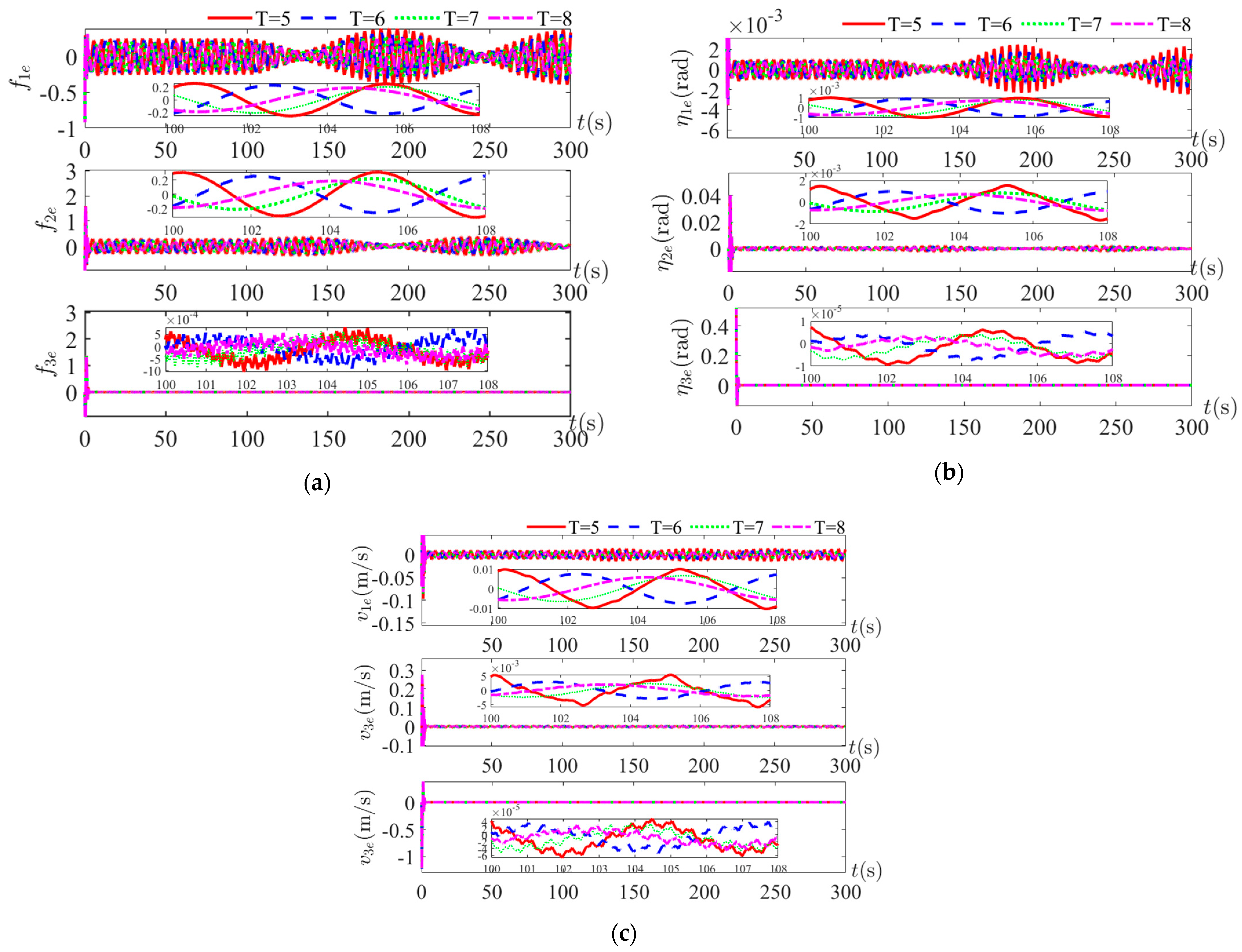
Figure 11 presents the observation error curves of complex disturbances, position and velocity under disturbances as shown in Equation (38). For disturbances with amplitude 11 times larger, the observations of the complex disturbances as shown in
Figure 11a are not as good as in the case of small disturbances, but the observation errors of the position and velocity states are within
. In the case of period variation, there is no significant difference between the simulation graphs under the four periods, and there is good adaptability for the period variation.
The simulation results shown in
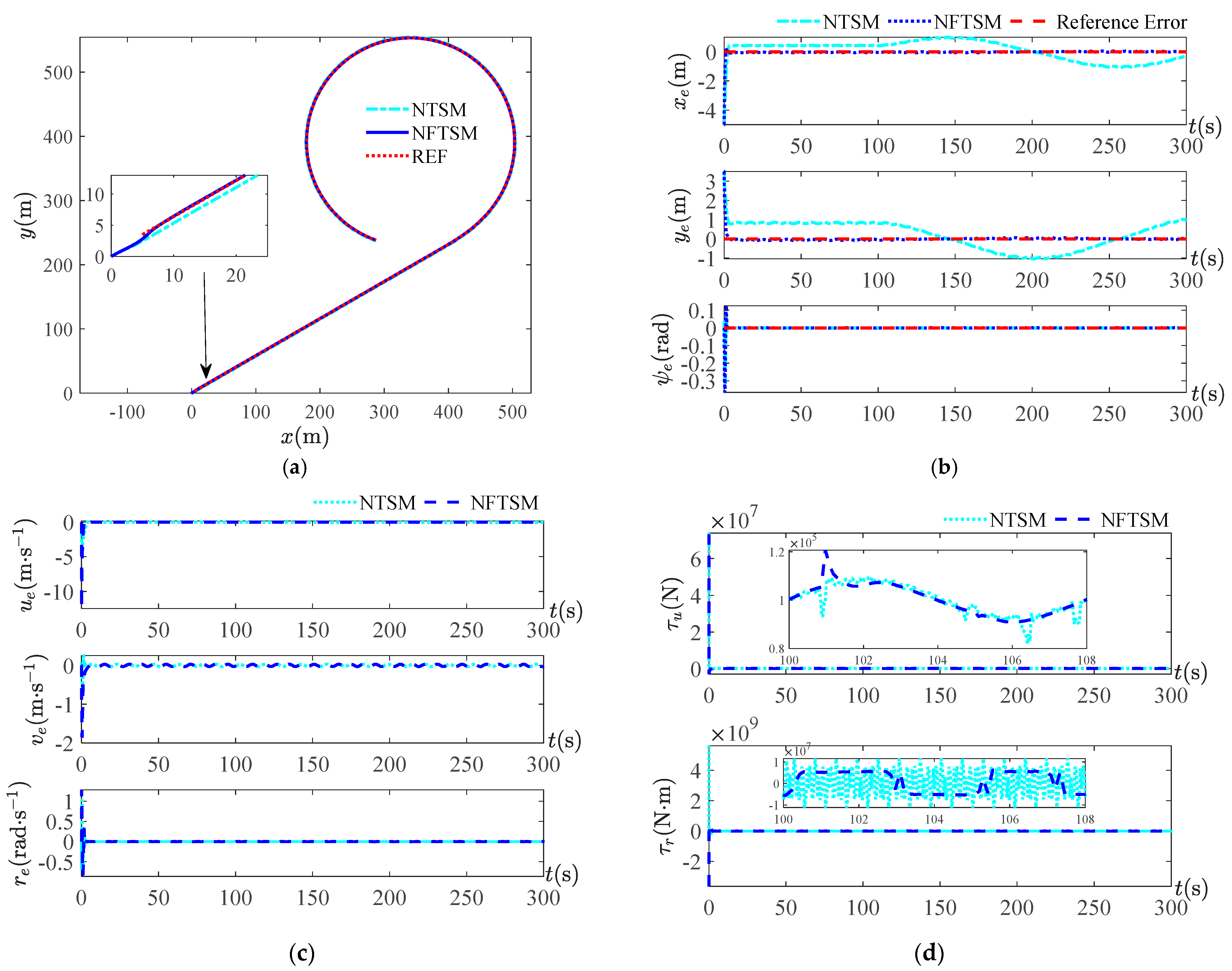
Figure 12,
Figure 13,
Figure 14 and
Figure 15 are obtained by varying the period
of the disturbances. Since the disturbances amplitude is 10 times the disturbances in Equation (37), the errors of the observed value obtained by NESO are relatively large compared to the small amplitude disturbances, which have an impact on the position tracking results and lead to a larger error. In the presence of observation errors, both control methods can achieve trajectory tracking control as seen in the trajectory tracking result graph, but the control effects are different. From the simulation results of
Figure 12 at the disturbance period of
, it is obvious from
Figure 12b that the control effect of the blue curve NFTSM of the control method used in this paper has a smaller error, and
Figure 12d shows that the chattering of the yaw moment is smaller. When the period becomes larger, as seen from the position error curves of the four periods, the tracking error of the control method in this paper is smaller, and its error curves are closer to the reference error curve of zero value. The simulation graph of the yaw moment at four periods shows that the control scheme proposed in this study has a smaller frequency of control output variation and less chattering.
The simulation results of the above two amplitudes and four periods show that the observation errors of position and velocity are less than and the complex disturbance less than in the case of small disturbance amplitude. In the case of a large disturbance of 10 times the small amplitude disturbance, the observation errors of position and velocity are less than , and the observation errors of the complex disturbance are less than . Under the disturbance of small amplitude and large amplitude disturbances, the position, velocity and composite disturbance observations with a small enough error can be obtained, which shows that the designed full state observer is feasible. The comparison of different periods of the two control methods highlights that the control method NFTSM in this paper has a better trajectory tracking effect, a smaller error and less controller chattering.
7. Conclusions
In this study, a method combining NESO and NFTSM is presented for trajectory control of an underactuated USV under the disturbances of wind, wave and current in external environment, in the presence of perturbation of the parameters of an underactuated USV model and in the absence of accurate information about the state of the system. Based on theoretical analysis, it is proved that the design process of NESO and NFTSM satisfies the Lyapunov stability condition. Two types of disturbances with 10 times difference in amplitude and four different periods are designed. The four period disturbances with the higher probability of generating wind and wave currents are chosen according to the scatter diagram of the sea states, and the numerical simulation verifies the effectiveness of NESO for all of the states observed. Finally, the NTSM and NFTSM are compared with the position, velocity and complex perturbation observations obtained by NESO, and the following conclusions can be drawn: (1) The stability demonstration and simulation results of NESO show that the designed observer can quickly approximate the actual complex disturbances and the underactuated USV system state, and the vessel position and vessel velocity observation errors for different periods of the two disturbances are less than , thus it is feasible and easier to implement the observer as a measurement module of the system to feedback the underactuated USV system state. (2) The simulation results show that the actual trajectory has a good approximation for the combined linear and circular trajectory, and the error curve shows the control scheme of NFTSM with a smaller error, and the error finally converges to the small neighborhood of zero, thus the probability of accidents is lower. (3) The simulation results show that under the conditions of environmental disturbances, model parameter uncertainty and state unpredictability, the control method of NFTSM can achieve rapid trajectory tracking control with less tracking error and less chattering in the process.
In future work, the focus will be on adaptive NESO, since the control accuracy is affected by the observer accuracy when using state feedback.
