Article

A Two-Stage Path Planning Algorithm Based on Rapid-Exploring Random Tree for Ships Navigating in Multi-Obstacle Water Areas Considering COLREGs

1
Intelligent Transportation System Research Center, Wuhan University of Technology, Wuhan 430063, China
2
National Engineering Research Center for Water Transport Safety (WTS Center), Wuhan University of Technology, Wuhan 430063, China
3
Inland Port and Shipping Industry Research Co., Ltd. of Guangdong Province, Shaoguan 512100, China
4
Centre for Marine Technology and Ocean Engineering (CENTEC), Instituto Superior Técnico, Universidade de Lisboa, Av. Rovisco Pais, 1049-001 Lisboa, Portugal
*
Authors to whom correspondence should be addressed.
J. Mar. Sci. Eng. 2022, 10(10), 1441; https://doi.org/10.3390/jmse10101441
Submission received: 2 September 2022 / Revised: 30 September 2022 / Accepted: 3 October 2022 / Published: 6 October 2022

Abstract

:
A two-stage ship path planning method is proposed, based on the Rapid-exploring Random Tree (RRT) algorithm, which is composed of global path planning and local path planning, addressing the important problem of finding an economical and safe path from start to destination for ships under dynamic environment, especially in waters with multiple obstacles and multiple target ships. The global path planning takes into consideration the ship draft and Under Keel Clearance to find navigable water using RRT, and reduces the path length and waypoints based on elliptic sampling and smoothing. In the local path planning, a dynamic collision risk detection model is constructed by introducing the Quaternion Ship Domain under a dynamic environment, and the restrictions of ship manoeuvrability and COLREGs are also involved. The simulation results show that the proposed model can find a satisfactory path within a few iterations, and keep clear of both static obstacles and dynamic ships. The research can be used to make and verify planned ship routes before sailing and to guide officers to make decisions regarding collision avoidance.

1. Introduction

With the development of shipping technologies in recent years, autonomous or intelligent ships have attracted increased attention [1,2,3,4]. To facilitate the progress of the regulatory scoping exercise, the autonomy degrees of ships are usually classified with four levels: ships with automated processes and decision support, remotely controlled ships with seafarers on board, remotely controlled ships without seafarers on board and fully autonomous ships [5,6]. For all ships, the question of how to ensure navigation safety is a top concern. According to statistics from 2014 to 2019, collision, contact and grounding in total account for 44% of all maritime accidents [7]. This percentage is even higher for bulk carriers, but is lower for containerships [8]. In the case of high-speed craft, which often operate in busy traffic areas the probability of collision, contact and grounding accidents is about 15% larger than for commercial vessels, reaching thus a percentage of the order of 60% [9].
Meanwhile, collisions and groundings sometimes bring serious casualties, property loss and environmental pollution [10,11], and most of them are caused by decision making failures and human errors under complex navigation environment and ship encounter scenarios [8,12,13,14]. Therefore, to improve the ship navigation safety, one effective strategy is to construct intelligent and autonomous decision support systems for ship route planning [15,16,17,18].
Automatic ship path planning is one of the hot issues in maritime transportation study [19,20,21]. The most important objective is to find a safe and economical route [22], which includes global and local path planning [23]. In practice, the planned route is first formulated by the second officer according to charts and navigation books before the whole voyage, and finally confirmed after the master review and puts forward correction/optimization when necessary [24]. The global path planning needs to choose a feasible route between the departure port and destination, and can keep a certain safe distance from under/above water obstacles, islands and reefs to ensure navigation safety [25,26,27]. Meanwhile, the planned path length and navigation manoeuvres frequency and the difficulty should be reduced as much as possible [21,28,29]. The objective of local path planning is to find a collision-free route with dynamic ships according to the International Regulations for Preventing Collision at Sea (COLREGs), with navigation experience, good seamanship and ordinary practice of seamen when encountering dynamic obstacles [30,31,32], such as target ships. The main purpose of path planning is to ensure navigation safety, and reduce the fuel consumption, the sailing time and path length as much as possible to improve efficiency [33], which for long distances needs to also account for the weather conditions [34].
In order to realize the above objectives, a path planning approach based on the Rapid-Exploring Random Tree (RRT) algorithm is proposed, which involves both global and local path planning. The rest of the article is organized as follows: Section 2 presents a literature review on the related research on path planning and the RRT algorithm. In Section 3, a modified path planning algorithm called RRTes, which involves the global and local path planning model, is proposed for ships navigating in a dynamic environment. A case study is presented along with results analysis and discussion in Section 4. Finally, conclusions and discussions are summarized in Section 5.

2. Literature Review

2.1. Global Path Planning

The global path planning method is suitable for the situation where there are only static obstacles and the navigation environment is available [19,35]. Grid-based path planning is a classical global planning approach. Lau et al. [36] proposed an increment update mechanism that only accesses the changing units in the configuration space for robot navigation. The approach works well in both 2D and 3D maps. Han et al. [21] presented a Predicted Trajectory Approach (PTA) for global motion planning of the under-actuated Unmanned Surface Vehicle (USV) based on grid navigation environment. Although the global motion planning can ignore the real-time performance, the computational efficiency of PTA is not satisfactory. In addition, heuristic algorithms are widely applied to finding feasible paths, and algorithms include Artificial Neural Network (ANN) [37], Evolution Algorithm (EA) [38], Fuzzy Logic (FL) [17,39] and A* Algorithm [19]. The heuristic path planning methods are usually realized in a random mode, and the path can be obtained by iterative convergence or mapping between input and output. In general, the global path planning methods usually can get satisfactory paths, but some more efforts are necessary for most of them when there are moving obstacles in the environment. Real-time decision making and path optimization are the problems to be solved in global path planning.

2.2. Local Path Planning

Based on the results of global path planning, the local planning model is usually introduced to update the path and ensure safe navigation in a real-time mode when collision risk with dynamic obstacles is at an acceptable level [35]. It mainly includes a collision risk measurement and collision avoidance decision-making [40]. Distance to Closest Point of Approach (DCPA) and Time to Closest Point of Approach (TCPA) are the most widely used indicators to measure the collision risk between encounter ships [41,42]. Cai et al. [43] proposed a collision risk model by synthesizing different Risk Influencing Factors (RIFs) including TCPA, DCPA, relative velocity and bearing angle. The Velocity Obstacle (VO) model is another type of collision risk evaluation approach from geographical perspective between encounter ships using the idea of velocity field [44]. Ship Domain (SD) is also one of the most widely used collision risk quantification model. The size of SD is determined by many factors, including ship characteristics (i.e., ship type, size, manoeuvrability), navigation waters (i.e., open waters, port waters, restricted waters), and environments (i.e., visibility, wind, current) [45].
In general, collision avoidance procedures are usually performed in a distributive mode [16,18,46], which means that each ship should make decisions from its own perspective while considering COLREGs, the intention of target ships as well as the uncertainties involved [47]. Zhang et al. [18] proposed a distributive and close-loop anti-collision decision support formulation considering COLREGs. The model can find a safe path for ships when all the ships comply with COLREGs, and consider ship manoeuvrability. Hu et al. [46] proposed a similar decision-making procedure by involving a Collision Risk Index (CRI) based on the Fuzzy Logic (FL) algorithm. The decision on course alteration as well as changing speed are considered when the CRI reaches a certain threshold. However, ship manoeuvrability is not considered.
There are also many deterministic and heuristic algorithms that have been introduced into local path planning, for instance, Artificial Potential Field (APF) [48], the Dijkstra algorithm [49,50], Ant Colony Optimization (ACO) [51], Genetic Algorithm (GA) [52], and Deep Reinforce Learning [53]. Most of them work well in certain circumstances, but their expansibility to different application scenarios needs to be further investigated.

2.3. RRT Algorithm

Rapid-exploring Random Tree (RRT) is a sampling-based algorithm that has been introduced into path planning [54,55]. The main idea of RRT is to perform random searches with fixed steps in the searching space, until reaching the destination. The searching procedure makes a trade-off between efficiency and randomness. RRT was first introduced to robot path planning and works well in many applications [56], and some research extended its application to ship path planning [57,58].
Chiang and Tapia [57] proposed a COLREG-RRT algorithm for surface vehicle navigation, and the path planning is realized by constructing virtual obstacles in the tree growth procedure in a scenario containing 20 obstacle ships. Enevoldsen et al. [58] proposed an informed RRT* algorithm, in which a feasible path is formulated using the traditional RRT algorithm and the planned path can be shortened in iterative mode. The results indicated that it has a high success rate and good adaptation to changes in the environment.
In order to ensure the ships navigation safety, not only global path planning is needed to avoid static obstacles, but also the local planning algorithm is necessary to avoid target ships or other moving obstacles. In this study, the RRT algorithm is used to synthesize the global path planning model and local path planning model. Based on the starting point of voyage and navigation environment, the global planning path is formed in the first step, and the planning process is to keep a certain distance from obstacles to ensure safe navigation. In local path planning, dynamic collision risk detection is integrated into RRT algorithm to adapt to dynamic obstacles. The local path planning algorithm will be activated if the ship identifies target ships when sailing along the global planned path. Moreover, in the local path planning method, the Quaternion Ship Domain (QSD) model is introduced to detect collision risk [59,60]. The local planning path is carried out considering ship manoeuvrability and COLREGs. Due to ship manoeuvrability, the angle range between planned path segments is restricted. The ellipse region is selected for sampling iteration, and the space was limited according to COLREGs. The planned path is optimized according to the path length.

3. Methodologies

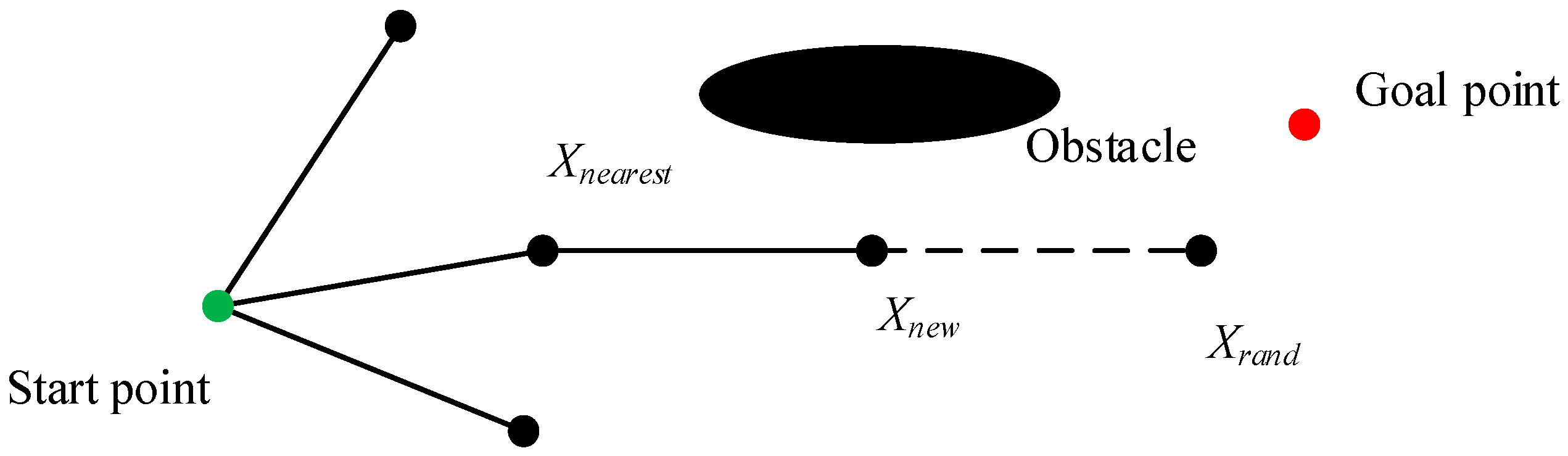
3.1. The RRT Algorithm

RRT is widely used in the field of robot obstacle avoidance and path planning [61]. The process of RRT algorithm expanding spanning tree is presented in Figure 1. It first randomly samples a point (Xrand) from the solution space with a probability (Pr), and selects the goal point with 1—Pr in each step. By doing so, it can make a trade-off between randomness and goal-orientation [62]. Then, Xrand is connected with the nearest node (Xnearest) in the existing tree and finds a new node (Xnew) randomly with the fixed distance step (Dp). If the path from Xnearest to Xnew is collision free, Xnew will be added to the tree. Otherwise, one more node will be sampled in the same way. The procedure continues until reaching the destination and a safe path can be found. The pseudo-code of the RRT algorithm expanding spanning tree is shown in Algorithm 1.
Algorithm 1: RRT algorithm expand spanning tree
Input: Start point Pstart; Goal point Pgoal; Set of static obstacles Osta; Distance step Dp; Samples probability Pr
Output: The RRT tree Ar
1:Create an array Ar as RRT tree and put the start point Pstart as its head node;
2:While Pgoal not in Ar
3: Generated a random number Rn between (0,1);
4: If Rn > Pr
5:  Sample a sampling point Xrand in free space;
6: Else
7:  Set goal point Pgoal as sampling point;
8: End If
9: Get nearest point form the sampling point Xnearest;
10: Generate new node Xnew with distance step Dp form Xnearest;
11: If no risk from Xnearest to Xnew with Osta
12:  Append Xnew to Ar;
13: Else
14:  Go to line 2;
15: End If
16: If distance between Xnew and Pgoal < Dp & no risk from Xnew to Pgoal with Osta
17:   Append Pgoal to Ar;
18: End If
19:End While
20:Return Ar
The RRT algorithm has advantage in finding a satisfactory path even in some very complex environments [63]. However, there are three issues that need to be considered when applying it to ship path planning. The first is the determination of the extent of navigable waters. The water depth is required according to ship draft to avoid grounding accidents [64]. The navigable water area is determined according to the requirements of the ship draft and under keel clearance (UKC). The second one is the collision detection. The RRT algorithm is initially used in a static environment and the collision detection is straightforward [65]. However, both own ship (OS) and target ship (TS) are moving and the collision detection should consider collision risk between them. The last issue is that ship manoeuvrability and COLREGs should be taken into consideration, which means that the turning angle between consecutive nodes should be limited within a range and the collision avoidance actions direction should be selected according to COLREGs.

3.2. Global Path Planning Based on RRT Algorithm

3.2.1. Navigable Map Construction Considering Grounding Risk

When determining the navigable water area, it is necessary to consider the ship draft in order to comply with the requirements of UKC to avoid the risk of grounding. Grounding is due to the fact that the ship draft is larger than the water depth in the sailing area, which often results in serious damage to the ship structure [66]. Therefore, before the global path planning, it is important to obtain the navigable map for the navigation environment information around the ship navigation water areas. The UKC is determined in accordance with the relevant navigation regulations of the authorities and is generally proportional to the ship draft [67]. Therefore, the water depth required by the ship in actual navigation can be calculated as follows:
Depth = − (draft + UKC)
UKC = k·draft
where k is the ratio of the UKC to the ship draft. According to [64], k is set to 0.2.
When the water depth required for navigation safety is determined, the boundary of the navigable area can be defined according to the chart isobaths and the minimum required water depth. Since the bathymetric points on the chart are stored in the form of coordinates, a series of coordinates on the chart isobaths line can be extracted to construct the original navigable map.
Meanwhile, the ship trajectory tends to deviate to some degree to both sides of the planned route because of the influence of hydrological and meteorological conditions [47,64]. To avoid the side grounding, a certain safe distance should be kept at least from the minimum required water depth at the chart. So, the original navigable map needs to be expanded by the certain safe distance ds from the minimum required water depth and the navigable map considering the grounding risk.

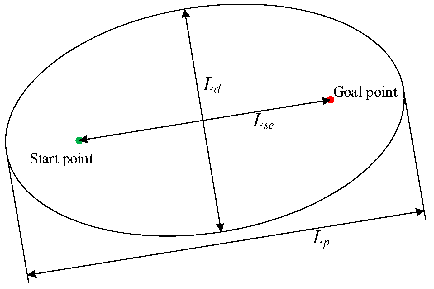
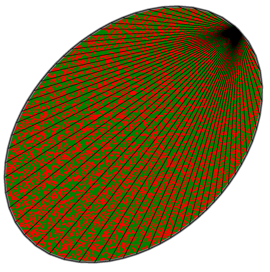
3.2.2. Sampling Space and Iterative Optimization

The path generated by RRT algorithm is non-asymptotically optimality in nature [68], so it needs to be optimized. When the planned path is found for the first time based on RRT algorithm, the path length is recorded as Lp. The sampling space within an ellipse is introduced which the start point and the goal point are the two focal points of the elliptical sampling space, as shown in Figure 2. Lp is taken as the major axis of the initial ellipse, and the initial minor axis Ld is calculated according to Equation (3).
L d = L p 2 L s e 2
where, Lse is the distance between the start and goal points. Due to the geometric characteristics of ellipse, the sum of the distance between the point in the region of the ellipse and the two focal points is less than Lp; and if a path smaller than Lp can be found, it must be in the region of the ellipse. When a better path is generated by iteration, the ellipse parameters can be further updated accordingly.
One issue that need to be resolved is sampling within the eclipse randomly and uniformly. To realize this, the ellipse is decomposed with a series of triangles, and the probability of the sample falling within any triangle is in proportion to its area. The sample distribution is shown in Figure 3, and the path will be optimized iteratively within the new sampling space and the path can be shortened accordingly while guaranteeing safety.
In order to reduce the ship manoeuvre frequency, the number of waypoints should be reduced as much as possible. For the planned path generated by the RRT algorithm, there are multiple nodes, which can be reduced by introducing smooth optimization, as shown in Figure 4. The smooth optimization starts from the goal point, and each node is connected to each node with its parent node, until there is a connection across the static obstacle (the red dashed line). Then, choose the last parent node (the blue point) as the current node to repeat the smooth optimization, until the start point can be connected. The points connected by the green solid line are the retained waypoints after smooth optimization.
According to Figure 4, smooth optimization can further reduce the path length on the basis of ensuring navigation safety. Meanwhile, smooth optimization can make the waypoints as few as possible and reduce the manoeuvring complexity.

3.2.3. Global Path Planning Algorithm Based on RRT Algorithm

With respect to the traditional RRT algorithm, the algorithm can achieve asymptotically optimization by choosing the elliptic sampling spaces iteratively. Meanwhile, the smooth optimization reduces the waypoints and further reduces the path length. The pseudo-code of global path planning algorithm is shown in Algorithm 2.
Algorithm 2: Global path planning algorithm based on RRT algorithm
Input: Start point Pstart; Goal point Pgoal; Set of static obstacles Osta; Distance step Dp; Samples probability Pr; Origin path Pathrrt; Optimized path Patho; Iterative time N
Output: The result of global path planning Pathg
1:Calculate the path length of Pathrrt (Lp), Lse and Ld
2:For i = 1,2,…N do
3: Construct or update elliptic sampling space
4: Pathi generation based on RRT algorithm and ellipse sampling space
5: Sent Pathi to smooth optimization
6: Calculate the length Ls of Pathi after smooth optimization
7: If Ls < Lp
8:  Assign Ls to the major axis Lp and update Ld;
9:  Set Pathi as the optimized path Patho;
10: End If
11:End For
12:Return Pathg = Patho

3.3. Local Path Planning under Dynamic Collision Risk

The planned route is generated by using the global path planning algorithm under the consideration of static obstacles. When the ship navigating along the planned route encounters the TS, it is necessary to take appropriate collision avoidance actions to ensure navigation safety [41,69]. Since the RRT algorithm is mainly used to solve the problem of static obstacle avoidance [65], local path planning under the dynamic risk detection should be formulated. Meanwhile, in order to guide the ship operator to make collision avoidance decisions, the local path planning should also involve the ship manoeuvrability and COLREGs.
There are two main methods of avoiding collision: changing speed or changing course. Course change is the primary consideration for collision avoidance, and speed change appears only when the environment does not allow a course change [70]. Meanwhile, due to the protective effect of special programs of ship propeller and large forces, it is very difficult for the ship to change speed in a short time [71]. Hence, this paper focuses on course alteration.

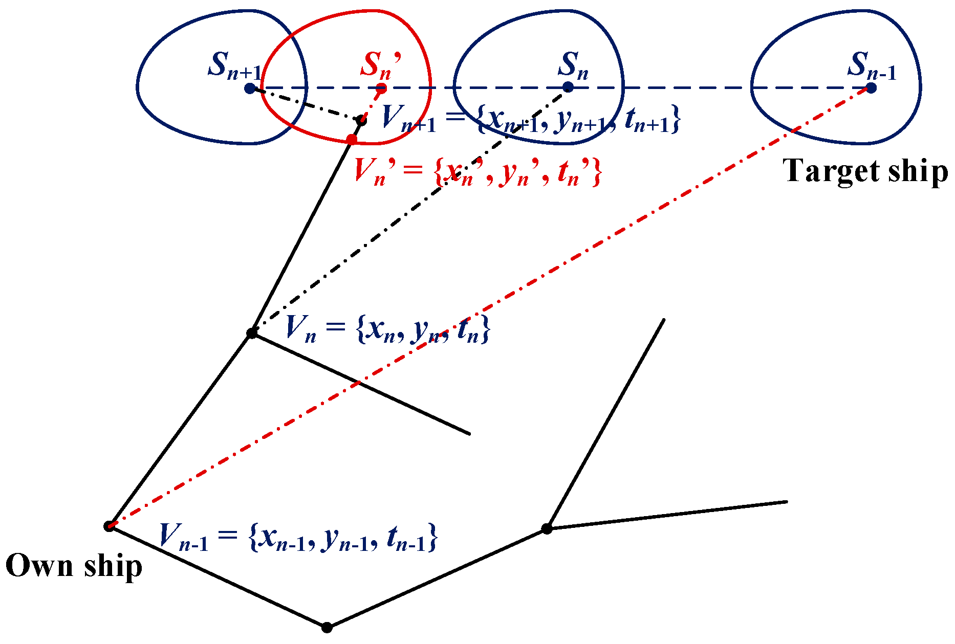
3.3.1. Dynamical Collision Risk Detection Based on Ship Domain

The size and shape of SD is influenced by many factors, including traffic density, visibility, ship size and speed, and manoeuvrability [72,73,74]. In this study, the QSD model is introduced to detect dynamic collision risk, and it takes COLREGs into consideration with a different safety radius in different bearing angles [59]. The QSD is shown in Figure 5, and the parameters are as follows:
{ R f o r e = ( 1 + 1.34 k A D 2 + ( k D T / 2 ) 2 ) L R a f t = ( 1 + 0.67 k A D 2 + ( k D T / 2 ) 2 ) L R s t a r b = ( 0.2 + k A D ) L R p o r t = ( 0.2 + 0.75 k A D ) L
where the parameter v is ship speed, and L is ship length. kAD and kDT represent gains of the advance and the tactical diameter, respectively, which are related to ship manoeuvrability, and can be calculated as follows [59]:
{ k A D = 10 0.3591 lg ( v ) + 0.0952 k D T = 10 0.5441 lg ( v ) 0.0795
Based on the QSD model, the dynamic collision detection model is formulated. As can be seen from Figure 6, one more parameter of t is added to the tree vertices, which means the time taken to reach the correspondent vertices. Assume the new sampling node is Vn+1 = {xn+1, yn+1, tn+1}, the time interval of ship navigating from Vn to Vn+1 can be decomposed into many pieces and they are considered as many consecutive moments. The positions, speeds and courses of OS and TS can be predicted and collision risk can be detected. If any domain violation occurs, i.e., the interval node Vn’ falls within the domain of TS, the path from Vn to Vn+1 is assumed to be obstructed. If there is no domain violation, the new path is considered to be collision-free and can be added to the tree. It should be noted that in the above analysis, although the analysis is carried out with the TS maintaining its course and speed, the model can also be used as long as the TS motion state can be predicted.
By adding the dynamic collision risk detection model to the RRT algorithm, it can generate the path that can not only avoid static obstacles, but also moving ships.

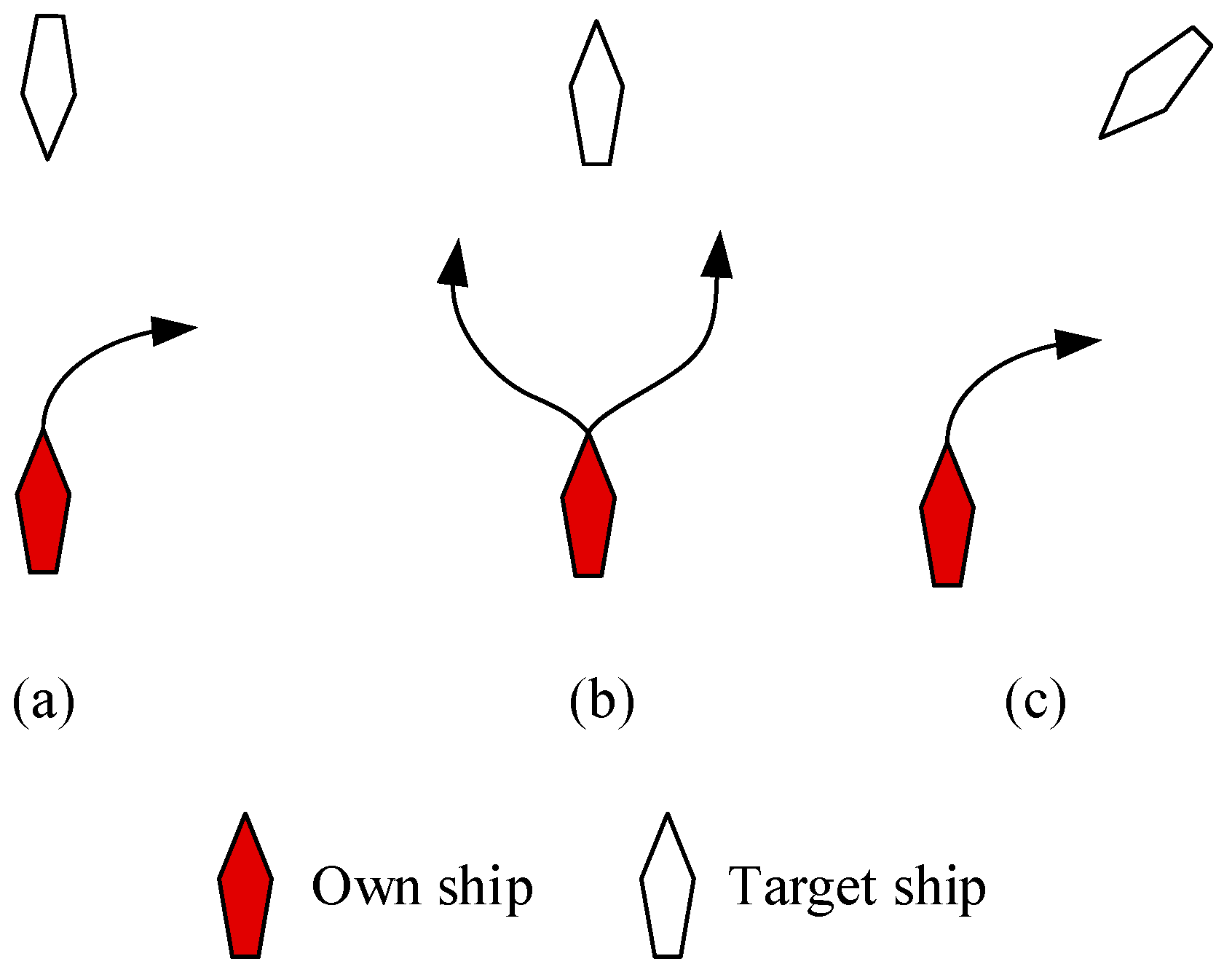
3.3.2. The Restriction of Ship Manoeuvrability and COLREGs

1.
Ship manoeuvrability restriction
The path should be planned in accordance with ship manoeuvring characteristics and evaluation of the collision avoidance effect, otherwise the ship cannot navigate along the planned route. Therefore, the max turning angle limitation should be considered according to the moving distance between neighbour nodes. This restriction can make the turning angles small enough to ensure that the ship is able to follow the planned path.
The manoeuvrability restriction function is added to the path planning algorithm in the random sampling part. It can select potential nodes in which the turning angle is smaller than the max turning angle. Then, the node which is the nearest from the sampling point is further selected as the parent node. By doing so it can guarantee that the turning angle along the whole path is small enough, and ships can follow the planned path under its manoeuvrability limitation. On the other hand, the sampling efficiency would be reduced to some degree, because the sampling failure would be more frequent with more restrictions. According to the simulation results of motion model in [75,76,77], the distance step Dp is set to 0.2 n miles, and the maximum turning angle Amax between two nodes is set to 5°.
2.
Sampling space selection considering COLREGs restriction
Another issue that should be considered is COLREGs compliance. When two power-driven ships encounter and have a collision risk, the give-way ship shall take action to avoid collision according to the COLREGs.
Rules 13~15 of COLREGs mainly include overtaking, head-on and crossing situations. The encounter situation can be determined according to the relative bearing and course, and the division range of encounter situation is given in [72]. Meanwhile, the distance of taking collision avoidance action under each situation should be quantified, in which 6 n miles is the generally accepted distance that officers begin to take collision avoidance action [41,42,78]. The schematic diagram of ship collision avoidance direction in each situation is shown in Figure 7.
According to Figure 7, the give-way ship can turn starboard or port in the overtaking situation, and it is recommended that the give-way ship turn starboard in the head-on and crossing situation. Therefore, in different situations, the planned path should comply with COLREGs by limiting the sampling space. In the overtaking situation, the sampling space is not limited, and the sampling space is limited to the right half ellipse in the head-on and crossing situations, as shown in Figure 8.

3.3.3. Local Path Planning Algorithm

In local path planning, the dynamic risk detection model is introduced by considering one extra parameter of time. At the same time, in order to adapt to the encounter situations, ship manoeuvrability restrictions are also included in local path planning algorithm. According to COLREGs, the ship collision avoidance distance and direction are quantified, and are considered in the planning path generation. The pseudo-code of local path planning algorithm under dynamic environment is shown in Algorithm 3.
Algorithm 3: Local path planning algorithm under ship dynamic collision risk
Input: OS position Xown; Next waypoint Xnp; static obstacles Osta; Distance step Dp; Dynamic obstacles Odyn; Samples probability Pr; Iterative time M; maximum turning angle Amax
Output: Local planned path Pathl
1:Create an array Al to store Local planned path Pathl
2:Set Xown and Xnp as the start and end point in local path planning;
3:Calculate the distance don between Xown and Xnp;
4:While Xnp not in Al
5: Constructed the elliptic sampling space, Lp = 3 * don, Lse = don;
6: Update the sampling space according to the ship encounter situation
7: Generated a random number Rn between (0, 1);
8: If Rn > Pr
9:  Sample a sampling point Xrand in free space;
10: Else
11:  Set goal point Xnp as sampling point;
12: End If
13: Get nearest point form the sampling point Xnearest;
14: Generate new node Xnew with distance step Dp form Xnearest;
15: Calculate the angle Anew between the Xnew and Xnearest
16: If Anew < Amax
17:  If no risk from Xnearest to Xnew with Osta and Odyn
  //using dynamic risk detection model to judge
18:   Append Xnew to Al;
19:  Else
20:   Go to line 7;
21:  End If
22:  Calculate the distance dng between Xnew and Xnp;
23:  If dng < Dp & no risk from Xnew to Xnp with Osta and Odyn
24:   Append Xnp to Al;
25:  End If
26: Else
27:  Go to line 7
28: End If
29:End While
30:Return Pathl = Al

4. Results and Discussion

In this section, a sea bottom map is constructed based on the chart depth, and the navigable map is formed considering the grounding risk. The grounding and collision risk is avoided by the global and local path planning.
The experiments are performed on a PC with an AMD Ryzen 9 5900HX with Radeon Graphics CPU with a speed of 3.30 GHz was manufactured by Advanced Micro Devices, Inc, 32 GB memory, and running the Windows 10 64-bit operating system. All hardware sourced from China; Python 3.7 is used for the experiments.

4.1. The Experimental Situation

A general cargo ship, which the ship length, width and the draft of full load are 96 m, 16.6 m and 5.8 m, respectively, is set as OS. According to Equations (1) and 2, the minimum water depth to ensure the ship safe navigation is 6.96 m, and ds is set to 0.1 n miles (185.2 m, more than 10 times of ship width) to avoid the side grounding. A topographic map of 20 × 20 n miles with water depth characteristics is generated as the global map containing environmental information, and the navigable map is further obtained according to the requirements of UKC and ds, as shown in Figure 9. Figure 9a shows the generated topographic map. Figure 9b shows the contour map and Figure 9c shows the navigable map considering grounding risk. The relationship between the minimum water depth and navigable map is shown in Figure 10, and the red line is minimum water depth line.
In global planning, (0, 0) and (20, 20) are used as the start and goal point to verify the proposed method based on navigable map, respectively. Then, the overtaking, crossing and head on situations between OS and TS are added to verify the collision avoidance decision-making performance.

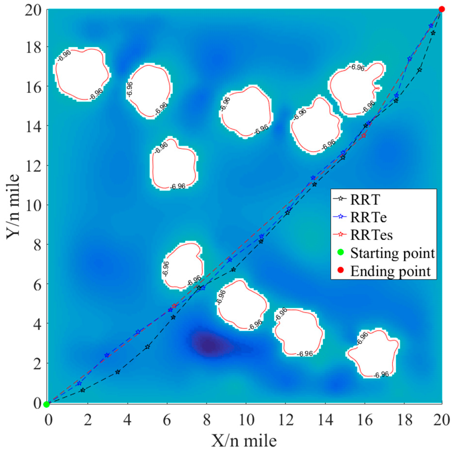
4.2. Result of Global Path Planning

Based on the navigable map shown in Figure 10, the traditional RRT algorithm, the RRT algorithm with elliptic sampling (RRTe), and RRT algorithm with elliptic sampling and smooth optimization (RRTes) are performed, respectively. The results with over 50 iterations are shown in Table 1 and Figure 11, where the dashed line with black, blue and red represent the shortest distance results of RRT, RRTe and RRTes, respectively. The relationship between iteration times and planned path length is shown in Figure 12.
According to Figure 11, all three algorithms can find a safe path based on the navigable map considering the grounding risk. Meanwhile, RRTes has an embedded smooth optimization function, which greatly reduces the number of nodes in path planning. In the process of global path planning, RRT is used to find the initial path firstly and the path length is 39.60 n miles, which is the initial result in Figure 12. The shortest path length and the number of waypoints (including the starting point) corresponding to RRT, RRTe and RRTes are 29.01 n miles and 4, 28.73 n miles and 16, 28.57 n miles and 16 after 50 iterations.
Figure 12 shows the process of the shortest path length with 50 iterations. It can be seen that the path length is significantly shortened with the increase in the number of iterations. RRTes can rapidly reduce the length of the planned path, which basically becomes stable after 13 iterations, and the shortest path appears after 18 iterations. RRTe can also reduce the planned path length quickly, which becomes stable after 16 iterations and with smaller improvement in the subsequent iterations. With the increase in the number of iterations, the planned path length of RRT shows a downward trend, which becomes stable after 35 iterations, and also has a small extent improvement in the subsequent iterations.
By comparing Figure 11 and Figure 12, RRTes can significantly reduce the number of waypoints in global path planning, so as to reduce the frequency and difficulty of ship manoeuvring. Meanwhile, when the initial path is consistent, RRTes can reach a relatively stable state in fewer iterations than RRT and RRTes, and the final path length of planning result is also shorter.

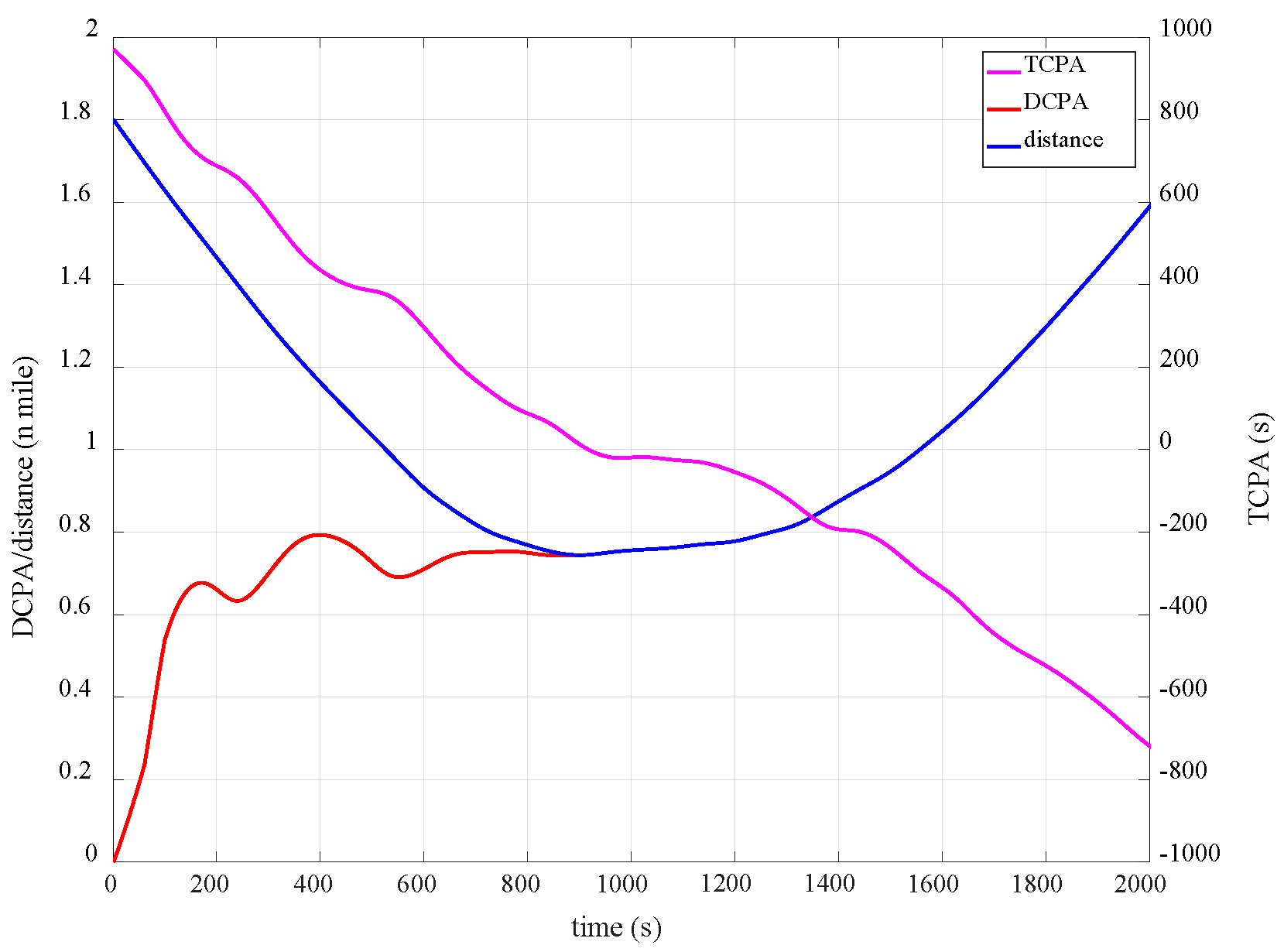
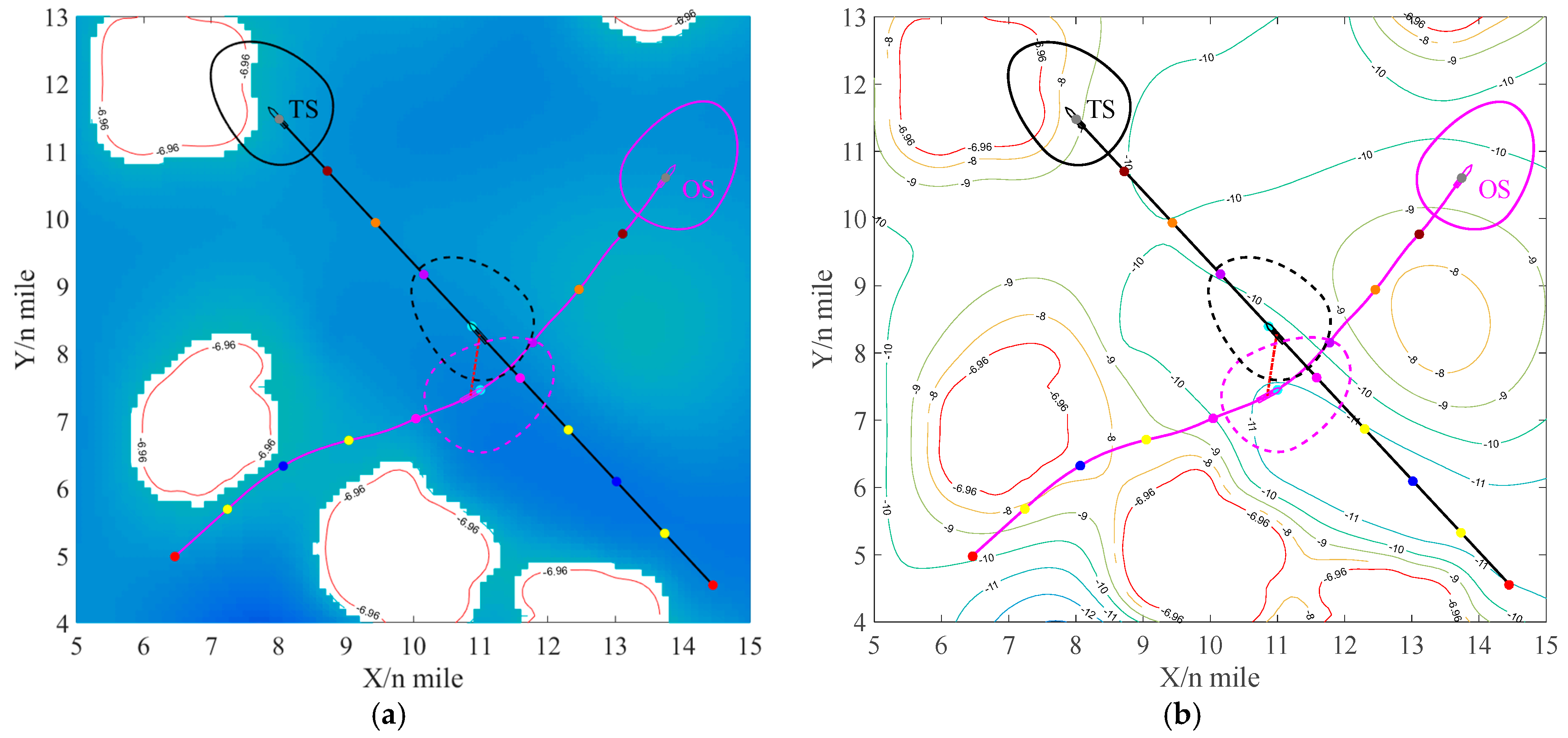
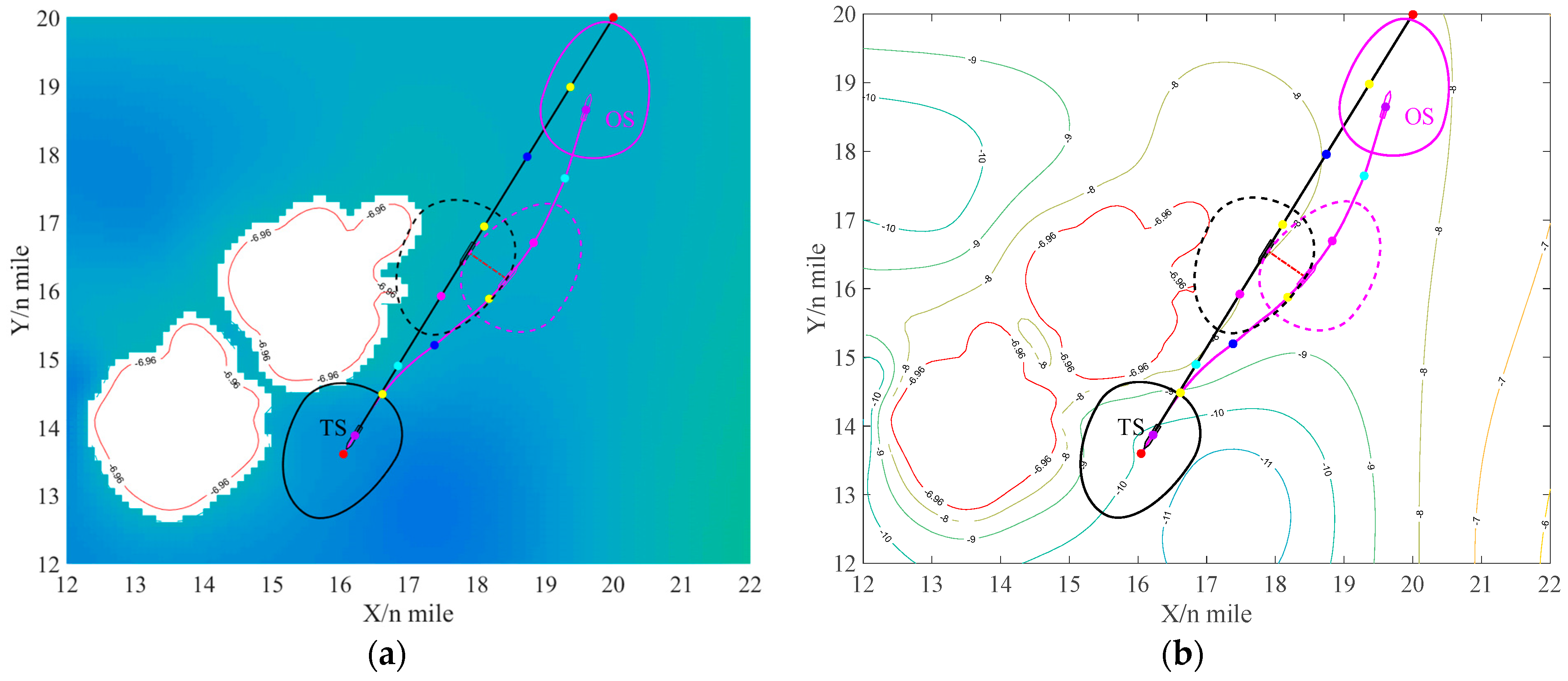
4.3. Result of Local Path Planning

To further verify the effectiveness of local path planning in dynamic obstacle scenarios, such as ship encounter, based on the results of global path planning, dynamic ships are placed near the global planned path and form overtaking, crossing and head-on situation with OS, respectively. The ship encounter parameters are shown in Table 2.
When the OS navigating from the start point (0, 0) to the goal point (20, 20), it encounters three TSs, so the OS needs to replan the path for three times.

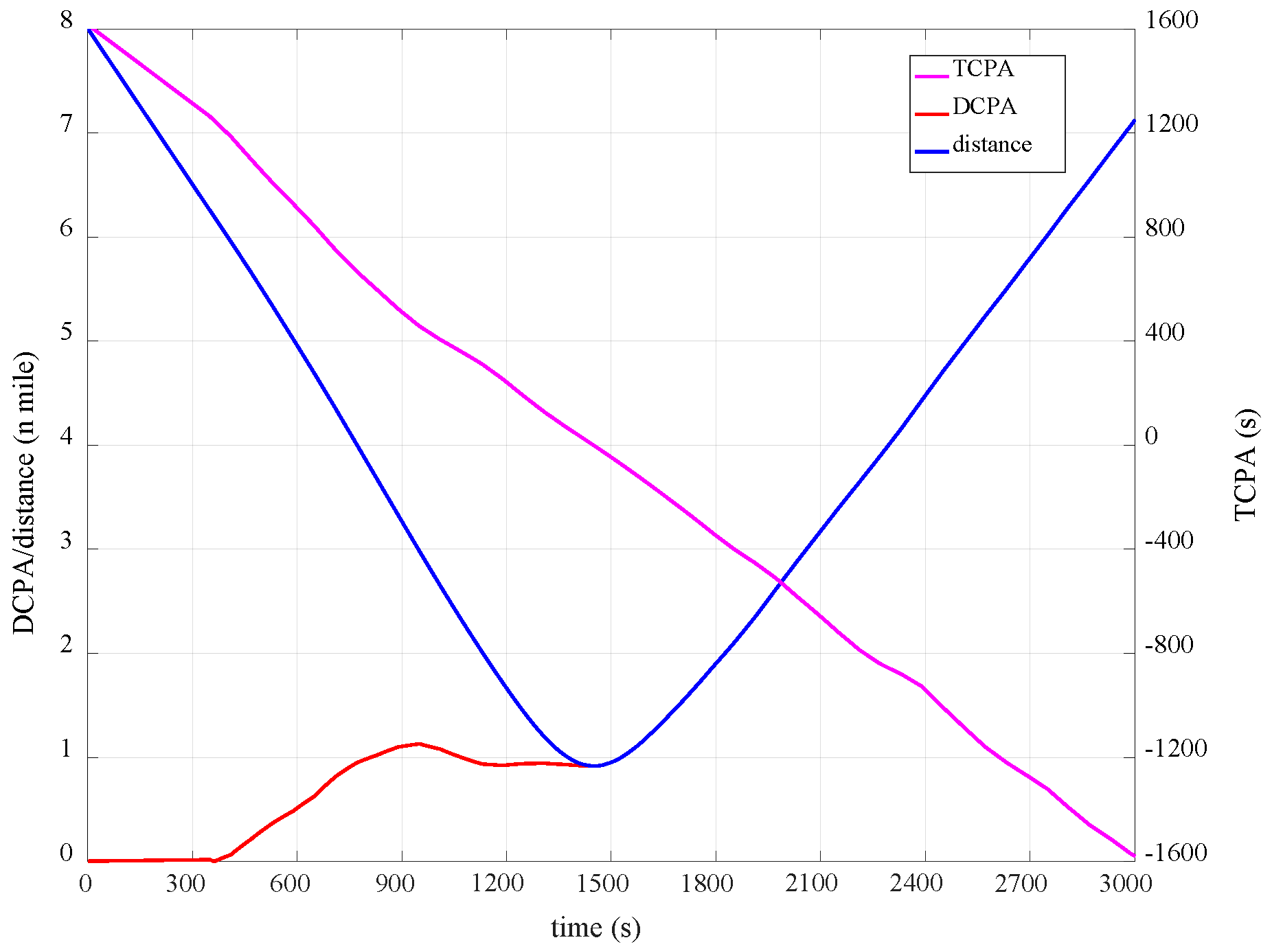
4.3.1. Overtaking Situation

In the overtaking situation, OS overtakes TS and is a give-way ship. The initial distance between them is 1.80 n miles, which is smaller than the collision avoidance distance in overtaking situation. Therefore, OS re-plans the path to keep clear of the TS immediately, and the results are shown in Figure 13. According to the re-planned path, DCPA, TCPA and distance between ships are calculated as shown in Figure 14. Figure 13a,b show the planned path of the ships in the navigable map and depth contour, respectively, where the magenta represents the OS, the black represents the TS (the overtaken ship) and the points with the same colour show the ships position synchronization. The time interval is 300 s, and the red dashed line is the line between the closest positions of ships. The dashed ship domain is the scope corresponding to the closest point of the ship. In Figure 14, the curve with magenta, red and blue represent TCPA, DCPA and distance varies with time, respectively. The ship motion parameters are obtained by interpolation calculation according to the planned path. Since RRTes are the waypoints planned with a constant step, cubic spline interpolation method is adopted to obtain changing curves.
According to Figure 13, the ship turns to starboard to avoid the TS. By analysing the COLREGs, turning to port or starboard both comply with COLREGs in the overtaking situation. However, the relative bearing of TS to OS is 0 at initial moment, and in QSD the starboard side is larger than the port side. So, turning to starboard can safely pass the TS with a smaller collision avoidance amplitude. As can be seen from Figure 14, DCPA is 0 at the initial moment, and increases rapidly after taking collision avoidance. The ships pass each other at the nearest distance of 0.74 n miles at t = 901 s, and the OS begins to resume heading for waypoints (6.46, 4.98) subsequently.

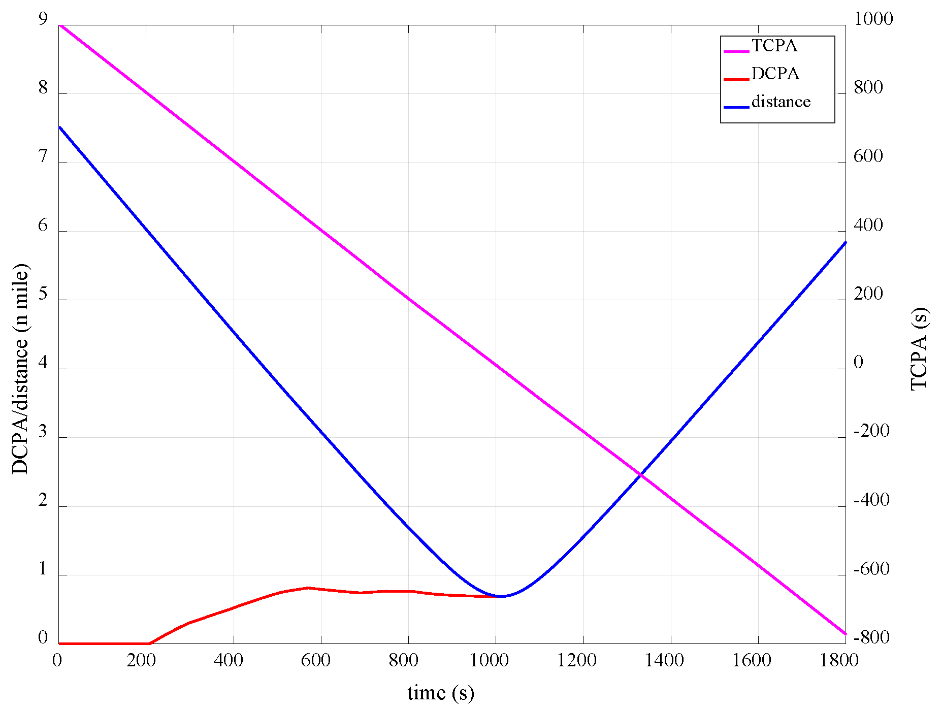
4.3.2. Crossing Situation

In this simulation, a crossing situation is formed between OS and TS. Note that OS is on the port of TS, OS is the give-way ship and the TS is the stand-on ship. The result of local path planning is shown in Figure 15, and the results of encounter parameters vary with time is shown in Figure 16.
The lines and colours in Figure 15 have the same meaning as in Figure 13. As can be seen from Figure 15, the OS turns to starboard to keep clear from the TS, which conforms to the requirements of COLREGs in the crossing situation. When ships are closest to each other, there is no invasion of each other’s ship domain, which proves that the algorithm can find a safe navigation path in navigable map. Based on Figure 15 and Figure 16, the distance between ships is larger than 6 n miles at the initial time which the distance is set to start taking actions according to [41,42]. Therefore, OS begins to act at 6 n miles (t = 402 s), and DCPA gradually increases from 0 at the initial time and stabilises at 0.92 n miles. The distance between ships reaches the nearest at t = 1450 s, and then the ship turns towards the next waypoint (16.05, 13.60).

4.3.3. Head-On Situation

According to COLREGs, both ships in the head-on situation have the same duty of collision avoidance and shall turn to starboard simultaneously and pass from port sides. However, in this simulation, there are obstacles on the starboard of the TS’s planned path, so it is not possible to take coordinated actions. Therefore, only the OS turns to starboard to keep clear. The results are shown in Figure 17, and the parameters curves are shown in Figure 18.
The lines and colours in Figure 17 have the same meaning as in Figure 13 and Figure 15. According to Figure 17 and Figure 18, the ship begins to turn to starboard at 6 n miles (t = 204 s), and the DCPA between ships gradually increased from 0. The nearest distance between ships is 0.69 n miles at t = 1012 s, with no ship domain violations, and then OS turns toward the destination (20.0, 20.0).

4.4. Discussion and Analysis

Figure 19 shows the results of the planned global path and local path. In conclusion, the planned paths can maintain a certain safe distance with static obstructions and dynamic ships. The global path planning is similar to the planning route before sailing practice to ensure that the water depth meets the requirements and avoid grounding.
When OS follows the planned path and encounters TSs, the collision avoidance scheme is activated through the steps of collision risk detection, situation assessment and collision avoidance decision-making, which has the same process and effect as the local path planning in this study. The global path planning and local path planning are two steps to avoid grounding accidents and collision accidents, respectively, which is in line with the navigation practice.
In global path planning, elliptic sampling is used to update and reduce the sampling space step by step. The smooth optimization model is introduced to further reduce the length of the planned path. Meanwhile, it can make the waypoint nodes as few as possible to reduce the navigation difficulty. According to Figure 11 and Figure 12, RRTes can achieve short path length in very few iterations. In 50 iterations, RRTes reaches the optimal solution of 28.57 n miles at 18 iterations and there are only four waypoint nodes. In comparison, the path length of RRT and RRTe are 29.01 n miles and 28.73 n miles, and with 16 waypoint nodes.
In the local path planning, the ship manoeuvrability restriction is taken into account to make the planned path more consistent with the ship motion characteristics, which is beneficial to verify the accuracy. At the same time, according to the action requirements of COLREGs, the direction of collision avoidance action is selected, so as to determine the sampling space area, so that the planning scheme comply with COLREGs. In the simulation, the closest distances are 0.74 n miles, 0.92 n miles and 0.69 n miles, respectively, for the overtaking, crossing and head-on situation. Although there are differences in distances, the encountered ships do not invade the domain of the other ships due to the difference in ship relative azimuth under different encounter situations. This is because the QSD and dynamical collision check algorithm is introduced to the algorithm. In this model, the ship bow direction is larger than the stern and the starboard side is larger than the port side, which is consistent with the cognition of ship collision risk in the actual navigation practice.
In terms of the running time, 50 iterations are carried out through the global planning and the local planning algorithm, and the results are shown in Table 3.
The average running time of global planning and local planning of three situations is 77.73 s, 37.48 s, 43.18 s and 34.24 s, respectively. Due to the global planning being completed before the voyage, calculation time is not significant, and the optimal path could be chosen after several iterations. Since the local planning involves ship collision avoidance, the time requirement becomes higher. According to the results of local planning, the time range of 50 iterations is 27.90~50.61 s, 31.25~57.53 s and 14.88~54.81 s, respectively. Considering that the ship speed is usually not very high, they can make timely response to the encounter situation to avoid collision using the proposed algorithm in most cases. Moreover, in practice, the TSs can be found at a long distance based on radar and other navigational aids, and the local planning path can be made some time before the encounter situation, and the subsequent scheme can be updated according to the evolution of the situation, so as to ensure the timeliness of making collision avoidance decisions.
It should be noted that RRT is a path planning algorithm based on random sampling, which a satisfactory planned path can be obtained through multiple iterations, but this path is not an optimal solution. This is also the common drawback of random algorithms. Meanwhile, the ship motion model is simplified and selected to be combined with the planning step to improve computation efficiency, but there are always some errors in the actual control and path following. This will be further studied on the real-time path planning optimization and path following control in the future research.

5. Conclusions

In this study, a modified path planning method called RRTes is proposed by adding more restrictions on RRT when considering the special case of ship path planning. The algorithm is synthesized with global path planning and local path planning. The former mainly considers the influence of ship draft and UKC to avoid grounding, and reduces the path length and nodes based on elliptic sampling and smooth optimization. In the latter model, a ship collision risk dynamic detection approach is constructed by using the QSD and dynamic collision detection algorithms, and is formed by considering the ship manoeuvrability restrictions and COLREGs. The results show that the proposed path planning method can find a satisfactory path with fewer iterations than the traditional RRT model, and can also keep clear from static obstacles and dynamic ships. The research can be used to make and verify ship planning routes before sailing and to guide ship collision avoidance decision-makings.
In the present study, some assumptions and simplifications are made, which can be further considered in the future research. For example, tidal information is not considered in the process of generating navigable maps. The qualitative grounding risk evaluation model can be introduced considering tidal effect in ocean environments. In the local path planning, the ship manoeuvrability is also simplified. Only changing the course and all ships complying with COLREGs is considered in local path planning. Therefore, the ship manoeuvrability under the effects of wind and current, and the speed change, the joint action of course and speed change, and the coordinated collision avoidance action under the uncertain state of the ship should be involved in future research.

Author Contributions

Conceptualization, J.Z. and D.W.; methodology, H.Z. and J.L.; software, H.Z. and D.W.; validation, J.Z., H.Z. and J.L.; formal analysis, C.G.S.; investigation, D.W. and C.G.S.; resources, J.Z. and C.G.S.; data curation, J.L. and D.W.; writing—original draft preparation, H.Z. and J.L.; writing—review and editing, J.Z. and C.G.S.; visualization, J.L. and D.W.; supervision, J.Z. and D.W.; project administration, J.Z.; funding acquisition, J.Z. All authors have read and agreed to the published version of the manuscript.

Funding

The research was supported by National Key Technologies Research and Development Program of China (No. 2019YFE0104600), National Natural Science Foundation of China (Nos. 51920105014; 52071247), the Fundamental Research Funds for the Central Universities (WUT: 223144002), and Natural Science Foundation of Hubei Province (No. 2019CFA039).

Institutional Review Board Statement

Not applicable.

Informed Consent Statement

Not applicable.

Data Availability Statement

Not applicable.

Conflicts of Interest

The authors declare no conflict of interest.

References

  1. Campbell, S.; Naeem, W.; Irwin, G.W. A review on improving the autonomy of unmanned surface vehicles through intelligent collision avoidance manoeuvres. Annu. Rev. Control. 2012, 36, 267–283. [Google Scholar] [CrossRef] [Green Version]
  2. Perera, L.P.; Ferrari, V.; Santos, F.P.; Hinostroza, M.A.; Guedes Soares, C. Experimental Evaluations on Ship Autonomous Navigation and Collision Avoidance by Intelligent Guidance. IEEE J. Ocean. Eng. 2015, 40, 374–387. [Google Scholar] [CrossRef]
  3. Liu, Z.; Zhang, Y.; Yu, X.; Yuan, C. Unmanned surface vehicles: An overview of developments and challenges. Annu. Rev. Control 2016, 41, 71–93. [Google Scholar] [CrossRef]
  4. Hu, L.; Naeem, W.; Rajabally, E.; Watson, G.; Mills, T.; Bhuiyan, Z.; Raeburn, C.; Salter, I.; Pekcan, C. A Multiobjective Optimization Approach for COLREGs-Compliant Path Planning of Autonomous Surface Vehicles Verified on Networked Bridge Simulators. IEEE Trans. Intell. Transp. 2020, 21, 1167–1179. [Google Scholar] [CrossRef] [Green Version]
  5. IMO. Takes First Steps to Address Autonomous Ships. Available online: https://www.imo.org/en/MediaCentre/PressBriefings/Pages/08-MSC-99-MASS-scoping.aspx (accessed on 25 May 2018).
  6. IMO. Outcome of the Regulatory Scoping Exercise for the Use of Maritime Autonomous Surface Ships (MASS); IMO: London, UK, 2021. [Google Scholar]
  7. EMSA. Annual Overview of Marine Casualties and Incidents 2020; ESMA: Lisbon, Portugal, 2020. [Google Scholar]
  8. Guedes Soares, C.; Teixeira, A.P. Risk assessment in maritime transportation. Reliab. Eng. Syst. Saf. 2001, 74, 299–309. [Google Scholar] [CrossRef]
  9. Antão, P.; Guedes Soares, C. Causal factors in accidents of high-speed craft and conventional ocean-going vessels. Reliab. Eng. Syst. Saf. 2008, 93, 1292–1304. [Google Scholar] [CrossRef]
  10. Zhang, G.; Thai, V.V. Expert elicitation and Bayesian Network modeling for shipping accidents: A literature review. Saf. Sci. 2016, 87, 53–62. [Google Scholar] [CrossRef]
  11. Fan, S.; Blanco-Davis, E.; Yang, Z.; Zhang, J.; Yan, X. Incorporation of human factors into maritime accident analysis using a data-driven Bayesian network. Reliab. Eng. Syst. Saf. 2020, 203, 107070. [Google Scholar] [CrossRef]
  12. Graziano, A.; Teixeira, A.P.; Guedes Soares, C. Classification of human errors in grounding and collision accidents using the TRACEr taxonomy. Saf. Sci. 2016, 86, 245–257. [Google Scholar] [CrossRef]
  13. Sotiralis, P.; Ventikos, N.P.; Hamann, R.; Golyshev, P.; Teixeira, A.P. Incorporation of human factors into ship collision risk models focusing on human centred design aspects. Reliab. Eng. Syst. Saf. 2016, 156, 210–227. [Google Scholar] [CrossRef]
  14. Wu, B.; Yip, T.L.; Yan, X.; Guedes Soares, C. Review of techniques and challenges of human and organizational factors analysis in maritime transportation. Reliab. Eng. Syst. Saf. 2022, 219, 108249. [Google Scholar] [CrossRef]
  15. Tsou, M.; Kao, S.; Su, C. Decision Support from Genetic Algorithms for Ship Collision Avoidance Route Planning and Alerts. J. Navig. 2010, 63, 167–182. [Google Scholar] [CrossRef]
  16. Perera, L.P.; Carvalho, J.P.; Guedes Soares, C. Fuzzy logic based decision making system for collision avoidance of ocean navigation under critical collision conditions. J. Mar. Sci. Technol. 2011, 16, 84–99. [Google Scholar] [CrossRef]
  17. Perera, L.P.; Carvalho, J.P.; Guedes Soares, C. Intelligent Ocean Navigation and Fuzzy-Bayesian Decision/Action Formulation. IEEE J. Ocean. Eng. 2012, 37, 204–219. [Google Scholar] [CrossRef]
  18. Zhang, J.; Zhang, D.; Yan, X.; Haugen, S.; Guedes Soares, C. A distributed anti-collision decision support formulation in multi-ship encounter situations under COLREGs. Ocean Eng. 2015, 105, 336–348. [Google Scholar] [CrossRef]
  19. Xie, L.; Xue, S.; Zhang, J.; Zhang, M.; Tian, W.; Haugen, S. A path planning approach based on multi-direction A algorithm for ships navigating within wind farm waters. Ocean Eng. 2019, 184, 311–322. [Google Scholar] [CrossRef]
  20. Huang, Y.; Chen, L.; Chen, P.; Negenborn, R.R.; van Gelder, P.H.A.J. Ship collision avoidance methods: State-of-the-art. Saf. Sci. 2020, 121, 451–473. [Google Scholar] [CrossRef]
  21. Han, S.; Wang, L.; Wang, Y.; He, H. An efficient motion planning based on grid map: Predicted Trajectory Approach with global path guiding. Ocean Eng. 2021, 238, 109696. [Google Scholar] [CrossRef]
  22. Thombre, S.; Zhao, Z.; Ramm-Schmidt, H.; Garcia, J.M.V.; Malkamaki, T.; Nikolskiy, S.; Hammarberg, T.; Nuortie, H.; Bhuiyan, M.Z.H.; Sarkka, S.; et al. Sensors and AI Techniques for Situational Awareness in Autonomous Ships: A Review. IEEE Trans. Intell. Transp. 2022, 23, 64–83. [Google Scholar] [CrossRef]
  23. Han, S.; Wang, L.; Wang, Y. A COLREGs-compliant guidance strategy for an underactuated unmanned surface vehicle combining potential field with grid map. Ocean Eng. 2022, 255, 111355. [Google Scholar] [CrossRef]
  24. IMO. International Convention on Standards of Training, Certification and Watchkeeping for Seafarers 1978. Commonw. Law Bull. 1984, 10, 1312. [Google Scholar]
  25. Kim, H.; Kim, D.; Shin, J.; Kim, H.; Myung, H. Angular rate-constrained path planning algorithm for unmanned surface vehicles. Ocean Eng. 2014, 84, 37–44. [Google Scholar] [CrossRef]
  26. Kim, H.; Kim, D.; Kim, H.; Shin, J.; Myung, H. An extended any-angle path planning algorithm for maintaining formation of multi-agent jellyfish elimination robot system. Int. J. Control. Autom. Syst. 2016, 14, 598–607. [Google Scholar] [CrossRef]
  27. Zhang, M.; Zhang, D.; Fu, S.; Kujala, P.; Hirdaris, S. A predictive analytics method for maritime traffic flow complexity estimation in inland waterways. Reliab. Eng. Syst. Safe. 2022, 220, 108317. [Google Scholar] [CrossRef]
  28. Claussmann, L.; Revilloud, M.; Gruyer, D.; Glaser, S. A Review of Motion Planning for Highway Autonomous Driving. IEEE Trans. Intell. Transp. 2020, 21, 1826–1848. [Google Scholar] [CrossRef] [Green Version]
  29. Wang, N.; Xu, H. Dynamics-Constrained Global-Local Hybrid Path Planning of an Autonomous Surface Vehicle. IEEE Trans. Veh. Technol. 2020, 69, 6928–6942. [Google Scholar] [CrossRef]
  30. Lazarowska, A. A new deterministic approach in a decision support system for ship’s trajectory planning. Expert Syst. Appl. 2017, 71, 469–478. [Google Scholar] [CrossRef]
  31. Wang, N.; Su, S. Finite-Time Unknown Observer-Based Interactive Trajectory Tracking Control of Asymmetric Underactuated Surface Vehicles. IEEE Trans. Control Syst. Technol. 2021, 29, 794–803. [Google Scholar] [CrossRef]
  32. Hinostroza, M.A.; Xu, H.; Guedes Soares, C. Motion Planning, Guidance, and Control System for Autonomous Surface Vessel. J. Offshore Mech. Arct. Eng. 2021, 143, 041202. [Google Scholar] [CrossRef]
  33. Wu, G.; Atilla, I.; Tahsin, T.; Terziev, M.; Wang, L. Long-voyage route planning method based on multi-scale visibility graph for autonomous ships. Ocean Eng. 2021, 219, 108242. [Google Scholar] [CrossRef]
  34. Vettor, R.; Guedes Soares, C. Development of a ship weather routing system. Ocean Eng. 2016, 123, 1–14. [Google Scholar] [CrossRef]
  35. Namgung, H. Local Route Planning for Collision Avoidance of Maritime Autonomous Surface Ships in Compliance with COLREGs Rules. Sustainability 2021, 14, 198. [Google Scholar] [CrossRef]
  36. Lau, B.; Sprunk, C.; Burgard, W. Efficient grid-based spatial representations for robot navigation in dynamic environments. Robot. Auton. Syst. 2013, 61, 1116–1130. [Google Scholar] [CrossRef]
  37. Yang, S.; Meng, M. An efficient neural network approach to dynamic robot motion planning. Neural Netw. 2000, 13, 143–148. [Google Scholar] [CrossRef]
  38. Tam, C.; Bucknall, R. Path-planning algorithm for ships in close-range encounters. J. Mar. Sci. Technol. 2010, 15, 395–407. [Google Scholar] [CrossRef]
  39. Perera, L.P.; Carvalho, J.P.; Guedes Soares, C. Solutions to the Failures and Limitations of Mamdani Fuzzy Inference in Ship Navigation. IEEE Trans. Veh. Technol. 2014, 63, 1539–1554. [Google Scholar] [CrossRef]
  40. Zhang, M.; Zhang, D.; Goerlandt, F.; Yan, X.; Kujala, P. Use of HFACS and fault tree model for collision risk factors analysis of icebreaker assistance in ice-covered waters. Saf. Sci. 2019, 111, 128–143. [Google Scholar] [CrossRef]
  41. Zhang, M.; Montewka, J.; Manderbacka, T.; Kujala, P.; Hirdaris, S. A Big Data Analytics Method for the Evaluation of Ship—Ship Collision Risk reflecting Hydrometeorological Conditions. Reliab. Eng. Syst. Saf. 2021, 213, 107674. [Google Scholar] [CrossRef]
  42. Liu, J.; Zhang, J.; Yan, X.; Guedes Soares, C. Multi-ship collision avoidance decision-making and coordination mechanism in Mixed Navigation Scenarios. Ocean Eng. 2022, 257, 111666. [Google Scholar] [CrossRef]
  43. Cai, M.; Zhang, J.; Zhang, D.; Yuan, X.; Guedes Soares, C. Collision risk analysis on ferry ships in Jiangsu Section of the Yangtze River based on AIS data. Reliab. Eng. Syst. Saf. 2021, 215, 107901. [Google Scholar] [CrossRef]
  44. Chen, P.; Huang, Y.; Mou, J.; van Gelder, P.H.A.J. Ship collision candidate detection method: A velocity obstacle approach. Ocean Eng. 2018, 170, 186–198. [Google Scholar] [CrossRef]
  45. Xin, X.; Liu, K.; Yang, X.; Yuan, Z.; Zhang, J. A simulation model for ship navigation in the “Xiazhimen” waterway based on statistical analysis of AIS data. Ocean Eng. 2019, 180, 279–289. [Google Scholar] [CrossRef]
  46. Hu, Y.; Zhang, A.; Tian, W.; Zhang, J.; Hou, Z. Multi-Ship Collision Avoidance Decision-Making Based on Collision Risk Index. J. Mar. Sci. Eng. 2020, 8, 640. [Google Scholar] [CrossRef]
  47. Yuan, X.; Zhang, D.; Zhang, J.; Zhang, M.; Guedes Soares, C. A novel real-time collision risk awareness method based on velocity obstacle considering uncertainties in ship dynamics. Ocean Eng. 2021, 220, 108436. [Google Scholar] [CrossRef]
  48. Lyu, H.; Yin, Y. COLREGS-Constrained Real-time Path Planning for Autonomous Ships Using Modified Artificial Potential Fields. J. Navig. 2019, 72, 588–608. [Google Scholar] [CrossRef]
  49. Niu, H.; Lu, Y.; Savvaris, A.; Tsourdos, A. An energy-efficient path planning algorithm for unmanned surface vehicles. Ocean Eng. 2018, 161, 308–321. [Google Scholar] [CrossRef] [Green Version]
  50. Silveira, P.; Teixeira, Â.P.; Guedes Soares, C. AIS Based Shipping Routes Using the Dijkstra Algorithm. TransNav 2019, 13, 565–571. [Google Scholar] [CrossRef]
  51. Wang, H.; Guo, F.; Yao, H.; He, S.; Xu, X. Collision Avoidance Planning Method of USV Based on Improved Ant Colony Optimization Algorithm. IEEE Access 2019, 7, 52964–52975. [Google Scholar] [CrossRef]
  52. Fiskin, R.; Atik, O.; Kisi, H.; Nasibov, E.; Johansen, T.A. Fuzzy domain and meta-heuristic algorithm-based collision avoidance control for ships: Experimental validation in virtual and real environment. Ocean Eng. 2021, 220, 108502. [Google Scholar] [CrossRef]
  53. Wang, S.; Yan, X.; Ma, F.; Wu, P.; Liu, Y. A novel path following approach for autonomous ships based on fast marching method and deep reinforcement learning. Ocean Eng. 2022, 257, 111495. [Google Scholar] [CrossRef]
  54. Wang, W.; Deng, H.; Wu, X. Path planning of loaded pin-jointed bar mechanisms using Rapidly-exploring Random Tree method. Comput. Struct. 2018, 209, 65–73. [Google Scholar] [CrossRef]
  55. Enevoldsen, T.T.; Galeazzi, R. Grounding-aware RRT⁎ for Path Planning and Safe Navigation of Marine Crafts in Confined Waters. IFAC-PapersOnLine 2021, 54, 195–201. [Google Scholar] [CrossRef]
  56. Li, Y.; Wei, W.; Gao, Y.; Wang, D.; Fan, Z. PQ-RRT: An improved path planning algorithm for mobile robots. Expert Syst. Appl. 2020, 152, 113425. [Google Scholar] [CrossRef]
  57. Chiang, H.L.; Tapia, L. COLREG-RRT: An RRT-Based COLREGS-Compliant Motion Planner for Surface Vehicle Navigation. IEEE Robot. Autom. Lett. 2018, 3, 2024–2031. [Google Scholar] [CrossRef]
  58. Enevoldsen, T.T.; Reinartz, C.; Galeazzi, R. COLREGs-Informed RRT* for Collision Avoidance of Marine Crafts. In Proceedings of the 2021 IEEE International Conference on Robotics and Automation (ICRA), Xi’an, China, 30 May–5 June 2021; pp. 8083–8089. [Google Scholar]
  59. Ning, W. A Novel Analytical Framework for Dynamic Quaternion Ship Domains. J. Navig. 2013, 66, 265–281. [Google Scholar]
  60. Silveira, P.; Teixeira, A.P.; Guedes Soares, C. A method to extract the Quaternion Ship Domain parameters from AIS data. Ocean Eng. 2022, 257, 111568. [Google Scholar] [CrossRef]
  61. Lonklang, A.; Botzheim, J. Improved Rapidly Exploring Random Tree with Bacterial Mutation and Node Deletion for Offline Path Planning of Mobile Robot. Electronics 2022, 11, 1459. [Google Scholar] [CrossRef]
  62. Wang, X.; Wei, J.; Zhou, X.; Xia, Z.; Gu, X. AEB-RRT: An adaptive extension bidirectional RRT algorithm. Auton. Robot. 2022, 46, 685–704. [Google Scholar] [CrossRef]
  63. Sintov, A.; Borum, A.; Bretl, T. Motion Planning of Fully Actuated Closed Kinematic Chains with Revolute Joints: A Comparative Analysis. IEEE Robot. Autom. Lett. 2018, 3, 2886–2893. [Google Scholar] [CrossRef]
  64. Zhang, M.; Kujala, P.; Hirdaris, S. A machine learning method for the evaluation of ship grounding risk in real operational conditions. Reliab. Eng. Syst. Saf. 2022, 226, 108697. [Google Scholar] [CrossRef]
  65. Wei, K.; Ren, B. A Method on Dynamic Path Planning for Robotic Manipulator Autonomous Obstacle Avoidance Based on an Improved RRT Algorithm. Sensors 2018, 18, 571. [Google Scholar] [CrossRef] [PubMed] [Green Version]
  66. Abaei, M.M.; Arzaghi, E.; Abbassi, R.; Garaniya, V.; Javanmardi, M.; Chai, S. Dynamic reliability assessment of ship grounding using Bayesian Inference. Ocean Eng. 2018, 159, 47–55. [Google Scholar] [CrossRef]
  67. Mate, B.; Robert, M.; Djani, M. Determining Restricted Fairway Additional Width due to Bank Effect for Fine Form Vessels. J. Navig. 2019, 72, 1435–1448. [Google Scholar]
  68. Li, J.; Li, C.; Chen, T.; Zhang, Y. Improved RRT Algorithm for AUV Target Search in Unknown 3D Environment. J. Mar. Sci. Eng. 2022, 10, 826. [Google Scholar] [CrossRef]
  69. Zhang, M.; Conti, F.; Le Sourne, H.; Vassalos, D.; Kujala, P.; Lindroth, D.; Hirdaris, S. A method for the direct assessment of ship collision damage and flooding risk in real conditions. Ocean Eng. 2021, 237, 109605. [Google Scholar] [CrossRef]
  70. Zhou, K.; Chen, J.; Liu, X. Optimal Collision-Avoidance Manoeuvres to Minimise Bunker Consumption under the Two-Ship Crossing Situation. J. Navig. 2018, 71, 151–168. [Google Scholar] [CrossRef]
  71. He, Y.; Jin, Y.; Huang, L.; Xiong, Y.; Chen, P.; Mou, J. Quantitative analysis of COLREG rules and seamanship for autonomous collision avoidance at open sea. Ocean Eng. 2017, 140, 281–291. [Google Scholar] [CrossRef]
  72. Gia, H.D.; Nam-kyun, I. The combination of analytical and statistical method to define polygonal ship domain and reflect human experiences in estimating dangerous area. Int. J. e-Navig. Marit. Econ. 2016, 4, 97–108. [Google Scholar]
  73. Zhang, L.; Meng, Q. Probabilistic ship domain with applications to ship collision risk assessment. Ocean Eng. 2019, 186, 106130. [Google Scholar] [CrossRef]
  74. Liu, K.; Yuan, Z.; Xin, X.; Zhang, J.; Wang, W. Conflict detection method based on dynamic ship domain model for visualization of collision risk Hot-Spots. Ocean Eng. 2021, 242, 110143. [Google Scholar] [CrossRef]
  75. Wang, X.; Liu, Z.; Cai, Y. The ship maneuverability based collision avoidance dynamic support system in close-quarters situation. Ocean Eng. 2017, 146, 486–497. [Google Scholar] [CrossRef]
  76. Xu, H.; Rong, H.; Guedes Soares, C. Use of AIS data for guidance and control of path-following autonomous vessels. Ocean Eng. 2019, 194, 106635. [Google Scholar] [CrossRef]
  77. Wang, T.; Wu, Q.; Zhang, J.; Wu, B.; Wang, Y. Autonomous decision-making scheme for multi-ship collision avoidance with iterative observation and inference. Ocean Eng. 2020, 197, 106873. [Google Scholar] [CrossRef]
  78. Cockcroft, A.N.; Lameijer, J.N.F. A Guide to the Collision Avoidance Rules: International Regulations for Preventing Collisions at Sea, 7th ed.; Butterworth-Heinemann: Oxford, UK, 2012. [Google Scholar]
Figure 1. Diagram of RRT algorithm expanding spanning tree.
Jmse 10 01441 g001
Figure 2. Diagram of ellipse sampling space construction.
Jmse 10 01441 g002
Figure 3. The result of random uniform sampling in the ellipse.
Jmse 10 01441 g003
Figure 4. Diagram of smooth optimization.
Jmse 10 01441 g004
Figure 5. The diagram of Quaternion ship domain (QSD).
Jmse 10 01441 g005
Figure 6. The illustrative demonstration of dynamic collision risk detection.
Jmse 10 01441 g006
Figure 7. Ship collision avoidance direction in each situation. (a) Head-on. (b) Overtaking. (c) Crossing.
Jmse 10 01441 g007
Figure 8. The sampling space result of half ellipse in head-on and crossing situation area.
Jmse 10 01441 g008
Figure 9. The schematic of navigable map. (a) Topographic map. (b) Contour map. (c) Navigable map.
Jmse 10 01441 g009
Figure 10. The relationship between the minimum water depth and navigable map.
Jmse 10 01441 g010
Figure 11. The shortest distance from the three global path planning algorithms (50 iterations).
Jmse 10 01441 g011
Figure 12. The relationship between iterations and planned path length.
Jmse 10 01441 g012
Figure 13. Local path planning in overtaking situation. (a) Navigable map. (b) Depth contour.
Jmse 10 01441 g013
Figure 14. The curves of ship encounter parameters with time in overtaking situation.
Jmse 10 01441 g014
Figure 15. Ship local path planning results in crossing situation. (a) Navigable map (b) Depth contour.
Jmse 10 01441 g015
Figure 16. The curve of ship encounter parameters varies with time in crossing situation.
Jmse 10 01441 g016
Figure 17. Ship local path planning result in head-on situation. (a) Navigable map. (b) Depth contour.
Jmse 10 01441 g017
Figure 18. The curve of ship encounter parameters varies with time in head-on situation.
Jmse 10 01441 g018
Figure 19. Comparison the results of global path planning and local path planning. (a) Navigable map. (b) Depth contour.
Jmse 10 01441 g019
Table 1. The nodes position and shortest path length of three algorithms.
No.Nodes Position/n miles
RRTRRTeRRTes
10.000.000.000.000.000.00
21.840.721.671.076.464.98
33.601.643.052.4916.0513.60
45.112.914.633.6720.0020.00
56.414.416.274.78The shortest path length:
RRT: 29.01 n miles;
RRTe: 28.73 n miles;
RRTes: 28.57 n miles.
67.715.907.925.89
79.476.839.287.32
810.858.2410.878.50
912.199.6912.279.90
1013.5611.1313.4911.47
1115.0012.4915.0012.74
1216.1514.1016.3014.24
1317.6815.3617.7015.63
1418.8816.9318.3717.49
1519.5618.7919.4519.15
1620.0020.0020.0020.00
Table 2. Parameters and encounter situation between OS and TSs.
Own Ship (OS)Target ship (TSs)Distance
/n Miles
Situation
Position/n MilesHeading/◦Speed/knPosition/n MilesHeading/◦Speed/kn
(0.0, 0.0)52.412.6(1.43, 1.10)52.46.31.80Overtaking
(6.46, 4.98)48.0(14.45, 4.56)318.012.68.00Crossing
(16.05, 13.60)31.7(20.0, 20.0)211.714.47.52Head-on
Table 3. The running time of global and local path planning.
Time/sGlobal Path PlanningLocal Path Planning
OvertakingCrossingHead-On
Average77.7337.4843.1834.24
Maximum162.7350.6157.5354.81
Minimum36.7327.9031.2514.88
Publisher’s Note: MDPI stays neutral with regard to jurisdictional claims in published maps and institutional affiliations.

