Article

Numerical Study on Attitude and Resistance of a Side-Damaged Ship during Steady Flooding

College of Marine and Energy Power Engineering, Wuhan University of Technology, Wuhan 430063, China
*
Author to whom correspondence should be addressed.
J. Mar. Sci. Eng. 2022, 10(10), 1440; https://doi.org/10.3390/jmse10101440
Submission received: 21 August 2022 / Revised: 2 October 2022 / Accepted: 2 October 2022 / Published: 6 October 2022
(This article belongs to the Special Issue Hydrodynamic Analysis on Ship Performance)

Abstract

:
The computational fluid dynamics method is used to analyze the attitude and resistance of a side-damaged frigate DTMB-5415 during steady flooding phase. The volume of fluid method is used to capture the interface between water and air. The shear stress transport k-ω model is employed to include the turbulence effect. The dynamic overlapping grid method is utilized to deal with the mesh update due to the ship motion in the simulation. First, the resistance, floating position and wave profile of an intact ship for different forward speeds are calculated. By comparing the results with experimental data, the calculation method is verified. Then, the resistances, attitudes and flow fields for the ship in intact, side-damaged (symmetrical and asymmetric flooding) and damage-repaired conditions are calculated and compared. For the side-damaged condition, the main change of the ship’s attitude is that the ship’s sinkage increases as the forward speed increases. Compared with symmetrical flooding, the ship’s heel increases during asymmetric flooding, while the sinkage decreases. For symmetrical flooding, the resistance of the ship increases significantly compared to the intact ship case. The increased resistance is mainly caused by the increase of ship sinkage. The existence of opening that affects the flow field causes additional increase of ship resistance. The pressure resistance is the main component of increased resistance, which is similar to the asymmetric flooding case.

1. Introduction

When a sailing ship encounters accidents such as groundings and collisions, the ship may be damaged. Sea water floods into compartments through the damaged opening. As a result, the safety of the damaged ship declines. In general, the ship flooding process in calm water after damage can be divided into three phases [1]: (I) transient phase, (II) progressive phase, (III) steady phase. In the first two phases, the water in the compartments accumulates rapidly, which will exacerbate the magnitude of ship motion such as heave, roll and pitch or even make the ship capsize [2,3,4]. If the ship survives the first two phases, it will undergo a steady flooding phase [5]. In this phase, the motions of the damaged ship and floodwater are almost stable. It is necessary to assess the safety of the damaged ship returning to port without external help. Compared to an intact ship, the attitudes of a damaged ship in calm water change significantly due to water flooding, which influences the performance of ship resistance. To provide relevant support for the damaged ship’s safe return to port, it is necessary to investigate the characteristics of the damaged ship’s attitudes and resistance during the steady flooding phase.
The ship’s resistance is normally evaluated by model test [6,7] and numerical simulation [8,9,10]. The method of model test requires special equipment and facilities and the costs are significant. With the advantages of relative low cost and flexibility on flow fields analysis, the method of numerical simulation based on computational fluid dynamics (CFD) had been widely used to predict the resistance of intact ships [11,12,13,14] and ships with bottom openings or moonpools [15,16]. Based on solving the Reynolds Averaged Navier Stokes (RANS) equation, the resistance characteristics for ships with large mid-bottom openings or moonpools were investigated by analyzing the flow fields around the ships. Also, different parameters of the bottom openings, such as positions, shapes and sizes, were investigated to show their influences on a damaged ship’s resistance performance [17,18,19]. It indicated that the damaged ship resistance is sensitive to changes of different parameters. Based on the flow field in the moonpool, the characteristics of ship resistance with a bottom opening were investigated [20,21]. By comparing different motion modes of the flow field in the moonpool, such as sloshing mode, piston mode, the coupled mode of sloshing and piston, the additional resistance influenced by the movement of flow field in the moonpool were investigated. The study can provide a powerful reference for the design of the moonpool type to improve the ship’s resistance performance. So, the types of moonpool were proposed to improve the ship’s resistance performance and sailing attitudes [22,23]. Different types of moonpools, such as the recess type and corner-cutting type moonpools, improved the motion of fluid in the moonpool. The additional resistance caused by the moonpool was effectively reduced. Besides the calm water condition, the ship resistance caused by the waves cannot be ignored. The characteristics of resistance for ships with bottom openings or moonpools were investigated in waves [24].
The above research studies are mainly focused on engineering ships with bottom openings. However, the positions of openings are not only at the bottom of the ship but also on the port or starboard in real accidents. The flow fields around ships and inside the compartments are different due to different damaged positions, which influences the characteristics of a damaged ship’s resistance. At present, there are few studies on the ship resistance for the side-damaged conditions. In addition, considering the ship’s internal layout, the compartments could be arranged with or without longitudinal bulkheads. The flooding cases can be categorized into two scenarios: symmetrical flooding and asymmetric flooding [25,26], in which the attitudes and resistance characteristics are difference. To provide more relevant support for the damaged ship’s safe return to port, in this paper, the resistance of a ship in side-damaged conditions were investigated, including symmetrical and asymmetric flooding. Based on the CFD method, the characteristics of attitudes and resistance of frigate DTMB-5415 in calm water were analyzed. The resistance, attitudes and flow fields for the intact, side-damaged and damage-repaired conditions were calculated and compared. The influence of opening and sailing attitudes on the flow field and ship resistance are discussed.

2. Methods

The CFD solver STAR-CCM+ is applied to investigate the ship resistance problem. Water and air are considered incompressible fluids. The volume of fluid (VOF) method is used to capture the interface between water and air. The fluid motion is governed by the continuity and the RANS equations described in the Cartesian coordinate system, as follows:
u i x i = 0
( ρ u i ) t + ( ρ u i u j ) x j = P x i + μ 2 u i x j x i τ i j x j + F i + S i
α t + x i ( α u i ) = 0
where t is the time; xi (i = 1, 2, 3) is the coordinate component (x, y, z); ui is the fluid velocity component in the xi-direction; ρ is the density of water; μ is the effective viscosity; P is the pressure; τij is the Reynolds stress; Fi is body force; Si is the source term in the xi direction; α is the fluid volume fraction; The shear stress transport k-ω model is employed to include the turbulence effect and combined with Y-plus (Y+) insensitive wall treatment to treat the flow behavior in the near-wall region.
For the discretization of the governing equations, the time terms are calculated by a second-order implicit scheme. In Equation (2), the convection term and diffusion term adopt the second-order upwind scheme and central differencing scheme, respectively. The convective term in Equation (3) adopts the second-order high-resolution interface capture scheme (HRIC). The semi-implicit method for pressure linked equation (SIMPLE) algorithm is employed for the pressure-velocity coupling.
Three degrees of freedom of motion (heave, roll and pitch) is considered in this study. The motion equations of the ship are as follows:
m η ˙ 3 = F 3
I 44 η ¨ 4 = M 4
I 55 η ¨ 5 = M 5
where m is the mass of the ship; η 3 is the vertical displacement of the center of gravity; F 3 is the vertical force acting on the ship; I 44 and I 55 are the ship moment of inertia relative to the center of mass about x-axis and y-axis, respectively; η 4 and η 5 are the roll angle and pitch angle, respectively; M 4 and M 5 are the roll and pitch moments acting on the hull, respectively.
The dynamic overlapping grid method is utilized to deal with the mesh update due to the ship motion in the simulation. The flow domain is divided into overlapping area and background area. By the interpolation calculation of overlapping grid, the flow field information is exchanged mutually.

3. Studied Cases and Validation

3.1. Ship and Compartment Models

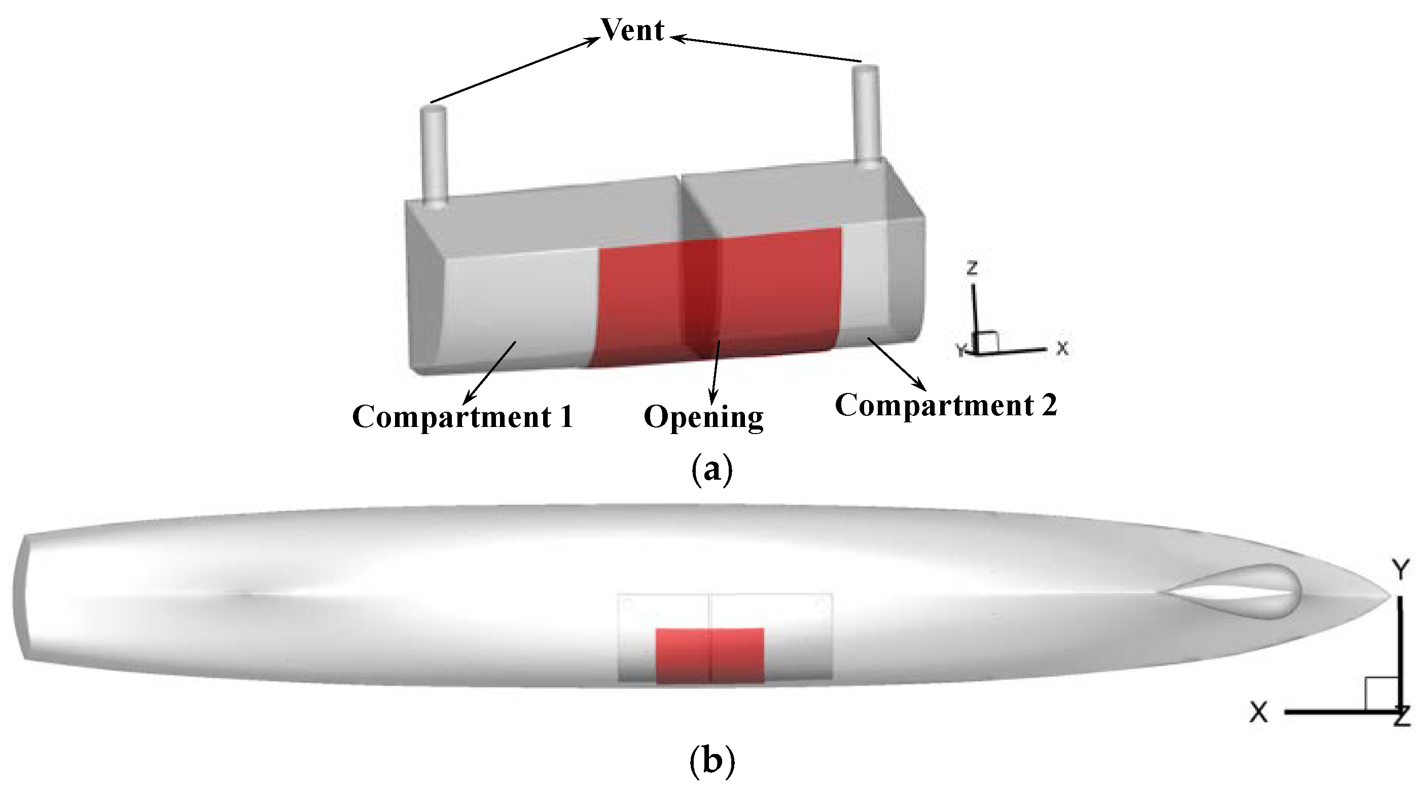
The frigate DTMB-5415 with two damaged compartments is selected as the ship to investigate the attitudes and resistance performance at different forward speeds. Normally, when a ship is damaged, it will return to port by itself or be towed to port with the help of a salvage boat at a low speed. Under war conditions, the damaged frigate may need to sail at a high speed. Thus, the Froude numbers, which are from 0.05 to 0.4, are selected to analyze. For a symmetrical flooding case, two damaged compartments are located at the midship along the x-axis, as shown in Figure 1. The total length of the two compartments is 17% of the ship’s length. The damaged condition is reasonable for a warship, which has to preserve functionality after two compartments are damaged [27]. Two vents are arranged at the top of the compartments for air ventilation during the flooding process. The scale ratio of the frigate model and damaged compartments is 1/24.83, as shown in Table 1 and Table 2. For an asymmetrical flooding case, the compartments are halved along the mid-longitudinal section. The port side parts are retained, as shown in Figure 2. Besides the damaged condition, the ships under intact and damage-repaired conditions are also investigated. Details of the repaired condition are described in Section 4.1.

3.2. Validation for Intact Ship

Series of experiments were conducted to measure the resistance, attitudes and wave patterns for the intact frigate DTMB-5415 at different forward speeds [28]. The length, width and water depth of the towing tank are 220 m, 9 m and 3.5 m, respectively. To verify the CFD model, the same cases, which were adopted in the experiment, are selected for numerical simulations. The calculated resistance and attitudes are compared with the experimental results. Figure 3 illustrates the computational domain, whose width and water depth are consistent with those of the experiment. The total length of the computational domain is 6.5 times that of the ship length. The upstream and downstream boundaries of the computational domain are set as the velocity inlet and pressure outlet, respectively. The remaining boundaries are set as no-slip wall. The computational domain is divided into an overlapping area and a background area. The background area remains static, while the motion of the overlapping area is consistent with the motion of the ship. To eliminate the wave reflection, a momentum source which brings a damping effect is added at the wave-dissipation area, which is 0.5 L away from the downstream boundary in the x-direction.
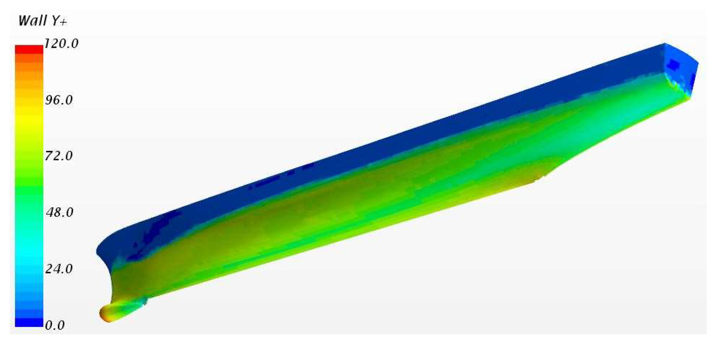
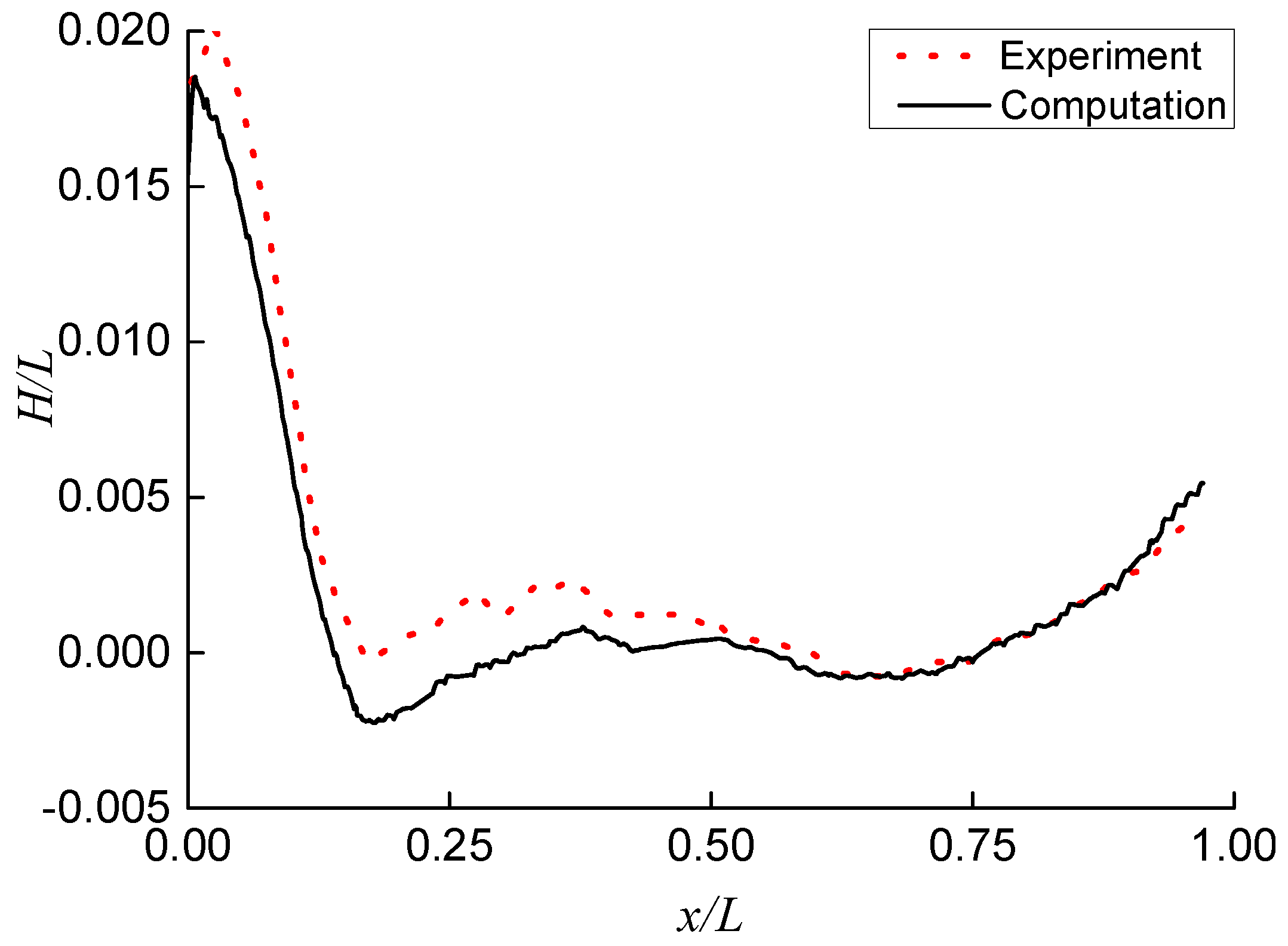
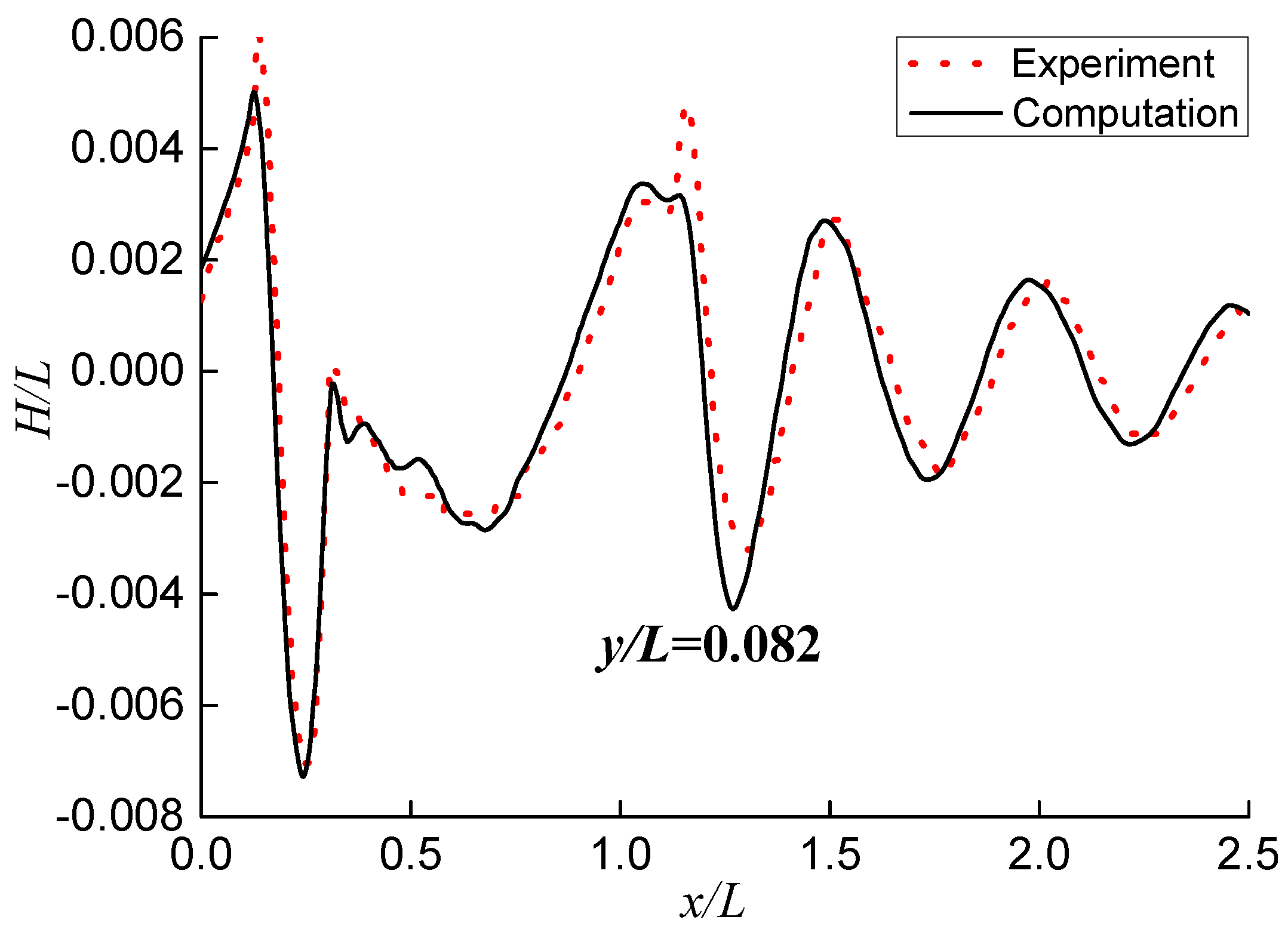
The accuracy of calculation is affected by the mesh arrangement and time step. First, the influence of mesh arrangement on calculation accuracy is discussed. To capture the wave profile accurately, the free surface mesh at the Kelvin area is refined in three directions. The whole mesh near the free surface is refined along the vertical direction. Away from the free surface and ship, mesh size gradually becomes larger. Based on the above principles, three sets of mesh are generated, namely, fine mesh, medium mesh and coarse mesh. Parameters of three sets of mesh are listed in Table 3, which includes the number of mesh, the element size near the free surface, the thickness of the first layer mesh and the corresponding Y+ value. In STAR-CCM+, when Y+ > 30, the wall function method is used to bridge the viscosity-affected region between the wall and the fully turbulent region. When Y+ < 1, the turbulence model for the low Reynolds number is used to resolve the viscosity-affected region. To avoid the switch of turbulent models near the wall region, in this study, Y+ on the wet surface of the ship is selected larger than 40, which guarantees that the wall function is utilized for different mesh arrangements. Figure 4 depicts the vertical view of medium mesh arrangement for the case of an intact ship. Figure 5 shows the Y+ distribution on the hull surface with medium mesh. The corresponding range of Y+ on the wet surface of the ship is from 40 to 120. Except for the wet surface, the Y+ on other parts of the ship (in the air phase) is from 0 to 10. The selected Froude number is 0.28, and the computational time step is 0.01 s. The calculation results of three sets of mesh listed in Table 4 are in good agreement with the experimental results. Compared with the experimental results, the maximum errors of calculated resistance and sinkage are approximately 1% and 12%, respectively. The trim angle in the numerical simulation and experiment are approximately 0.5° and 0.1°, respectively, both of which are very small. The absolute error is less than 0.4°. Table 5 summarizes the results of mesh dependence study for the resistance, e.g., convergence ratio (RG), order of accuracy (PG), correction factor (CG), simulation numerical error (δRE), uncertainty (UG) and its proportion of total resistance of model test (%D). Note that RG is greater than 0 and less than 1, the calculated resistance is monotonically convergent among three sets of mesh. Figure 6, Figure 7 and Figure 8 depict the comparisons of wave elevations on the hull surface and at different longitudinal sections obtained by numerical simulation and experiment. The calculated wave elevation on the hull surface has an average deviation of 10 mm. It indicates that the distribution of pressure on the hull surface in the CFD simulation is different from that in the experiment. Therefore, the trim angle obtained in the numerical simulation deviates a little from the experimental measurement. For the area away from the ship, the wave elevations obtained with CFD are in good agreement with the experimental results.
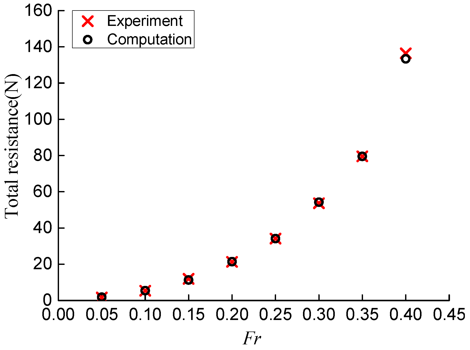
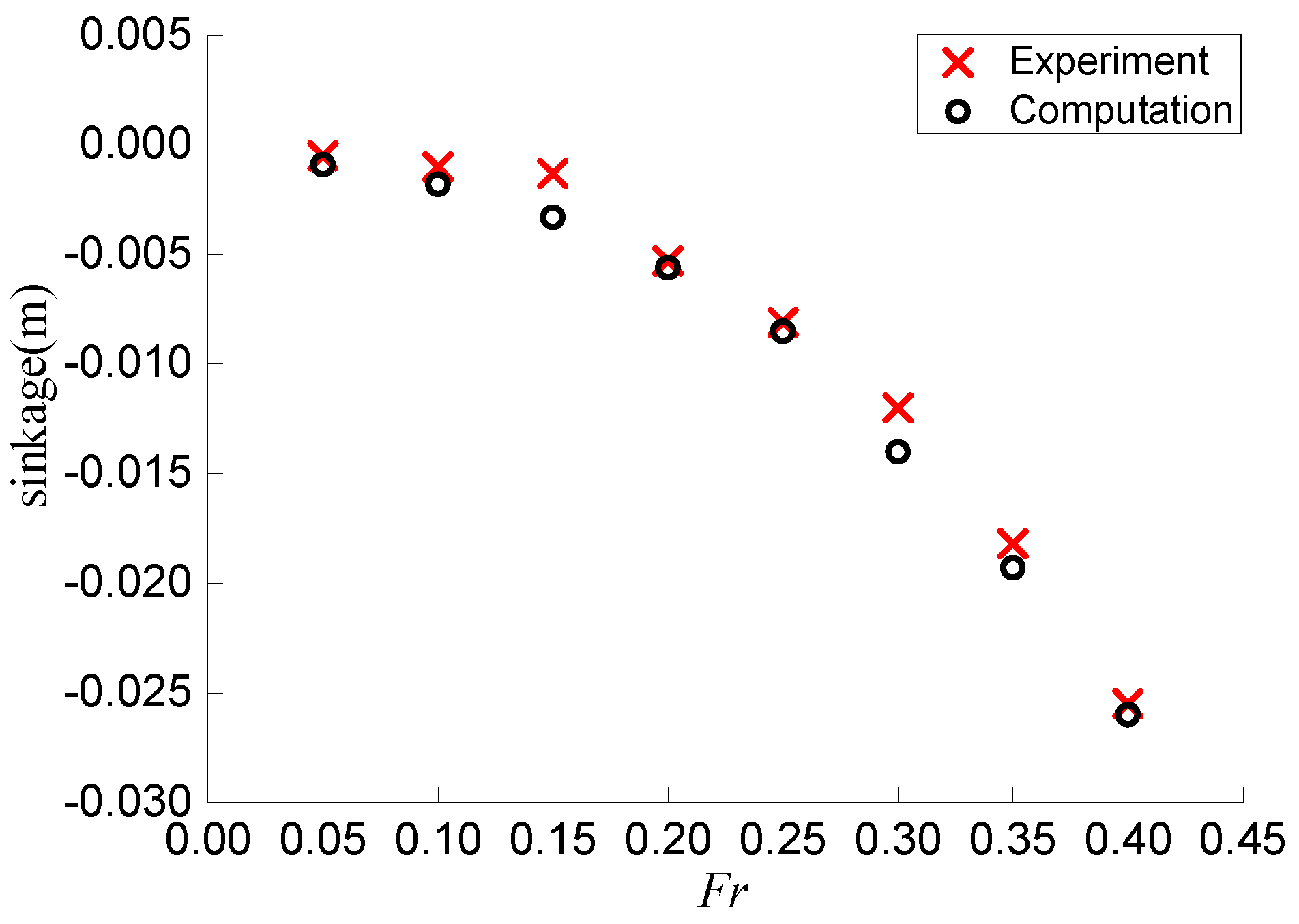
Three different time steps (i.e., 0.0025 s, 0.005 s and 0.01 s) and medium mesh are selected for time dependence investigation. The calculated resistance and attitudes based on different time steps are listed in Table 6, which present similar accuracy. Similar to mesh dependence study, the results of time dependence study for the resistance are summarized in Table 7. The RT is also greater than 0 and less than 1, the calculated resistance is monotonically convergent among three different time steps. The above comparisons show that the selection of medium mesh and time step of 0.01 s can guarantee the accuracy and efficiency of calculation and is adopted for the following analysis. The resistance and sinkage of the intact ship (Fr = 0.05~0.4) are compared with the experimental data, as shown in Figure 9 and Figure 10. Good agreements between numerical and experiment results are obtained.

4. Attitude and Resistance of Damaged Ship

4.1. Symmetrical Flooding

The medium mesh and time step 0.01 s are selected to calculate the resistance and attitudes of the ship during symmetrical flooding at different forward speeds. Figure 11 depicts the mesh arrangement for the case of symmetrical flooding. Three mesh sizes inside the compartments (i.e., 0.007 m, 0.01 m and 0.014 m) are selected for mesh dependence investigation. The results are summarized in Table 8. The selection of mesh size of 0.01 m can guarantee the accuracy and efficiency of calculation and is adopted for the following analysis. The total number of mesh in computational domain is approximately 3.57 million. The calculated attitudes of the damaged ship are compared with the results of an intact ship and listed in Table 9. The heel and trim angles of the ship during symmetrical flooding at different forward speeds are small. They are similar to the zero-speed condition. With the increase of the forward speed, the sinkage of the ship increases gradually and becomes larger than that for the zero-speed condition. Compared with the intact ship, the attitudes of the ship during symmetrical flooding are increased, mainly due to the increase of the draught by more than 20%. Correspondingly, the changes of the flow field around the damaged ship cause the resistance to increase significantly. The increased resistance for the ship during symmetrical flooding ranged from 27% to 42% at different forward speeds, as listed in Table 10.
For further analyzing the influence of ship attitudes and damage on ship resistance, the damage-repaired case is investigated. The results are listed in Table 10. For the damage-repaired case, the damaged opening is closed. The ship attitudes (sinkage, heel and trim) in the damage-repaired case are adjusted to be equal to those in the symmetrical flooding case, as shown in Table 9. The resistance and wave patterns of the damage-repaired case are compared with those of the symmetrical flooding case, aiming to analyze the influence of the existence of the opening on the resistance of the ship. The results for three cases (i.e., intact case, symmetrical flooding case and damage-repaired case) are compared. The results show that the changes of ship’s attitudes (almost the increase of draught) cause the increase of resistance by 19% to 34% at different forward speeds. The existence of the damaged opening induces an additional resistance increase from 6% to 13%. The results in Table 10 also show that the intact ship’s resistance is the smallest among three conditions at the same speed, while the resistance of the ship under symmetrical flooding is the largest. It can be seen that the additional resistance of the ship under symmetrical flooding is mainly caused by the increase of the ship’s draught, while the disturbance of the opening to the flow field causes the further increase of the ship resistance to some extent.
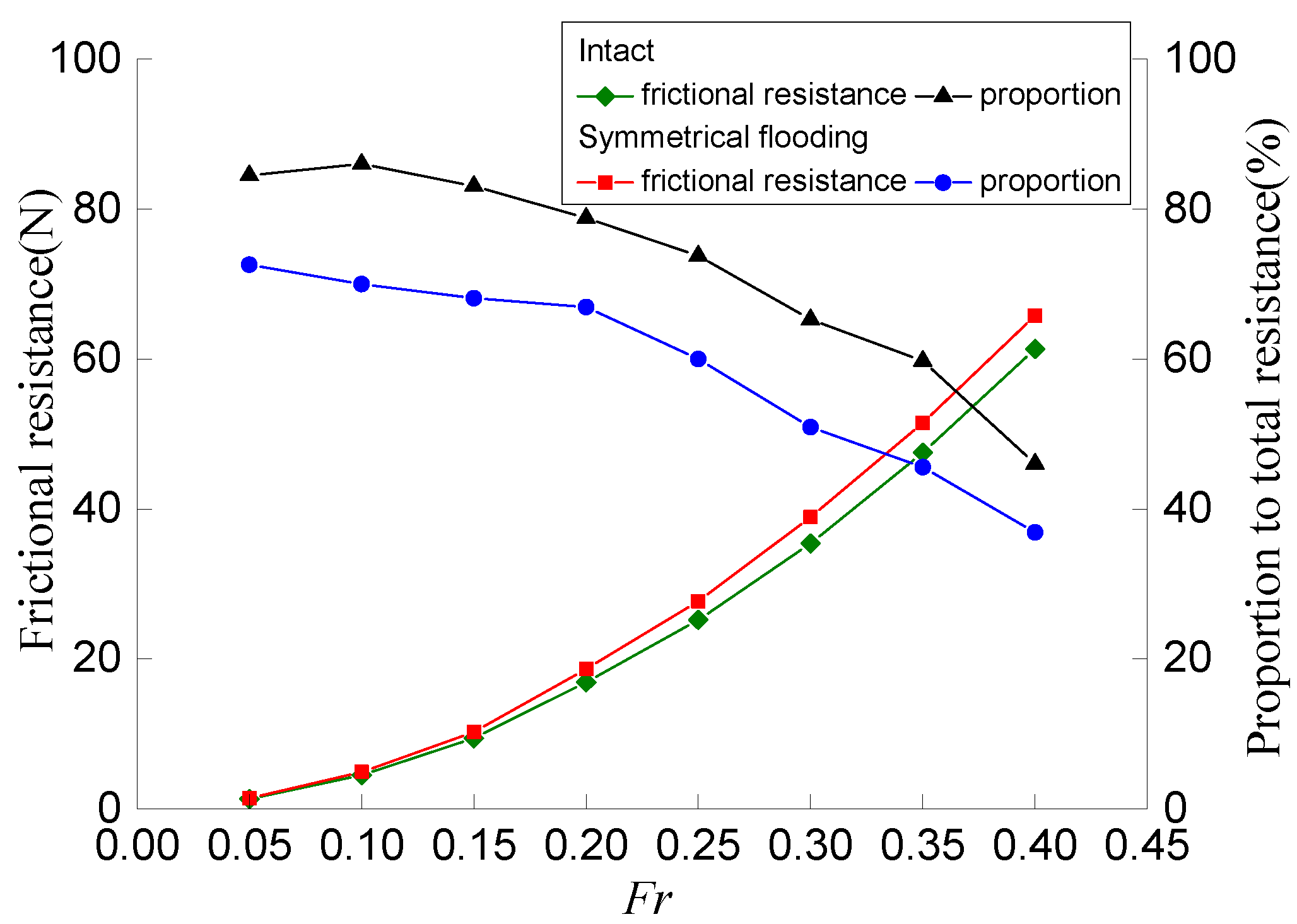
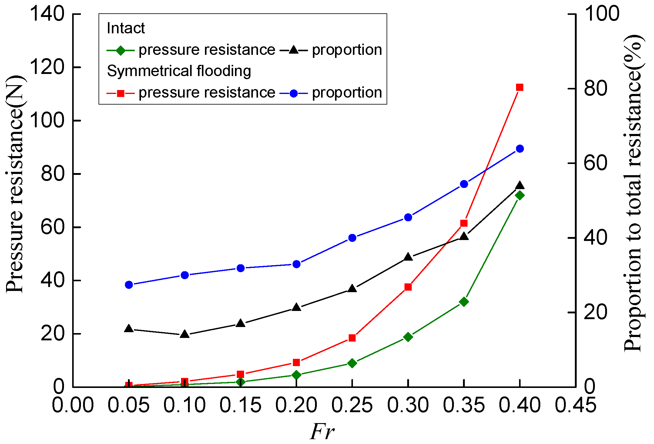
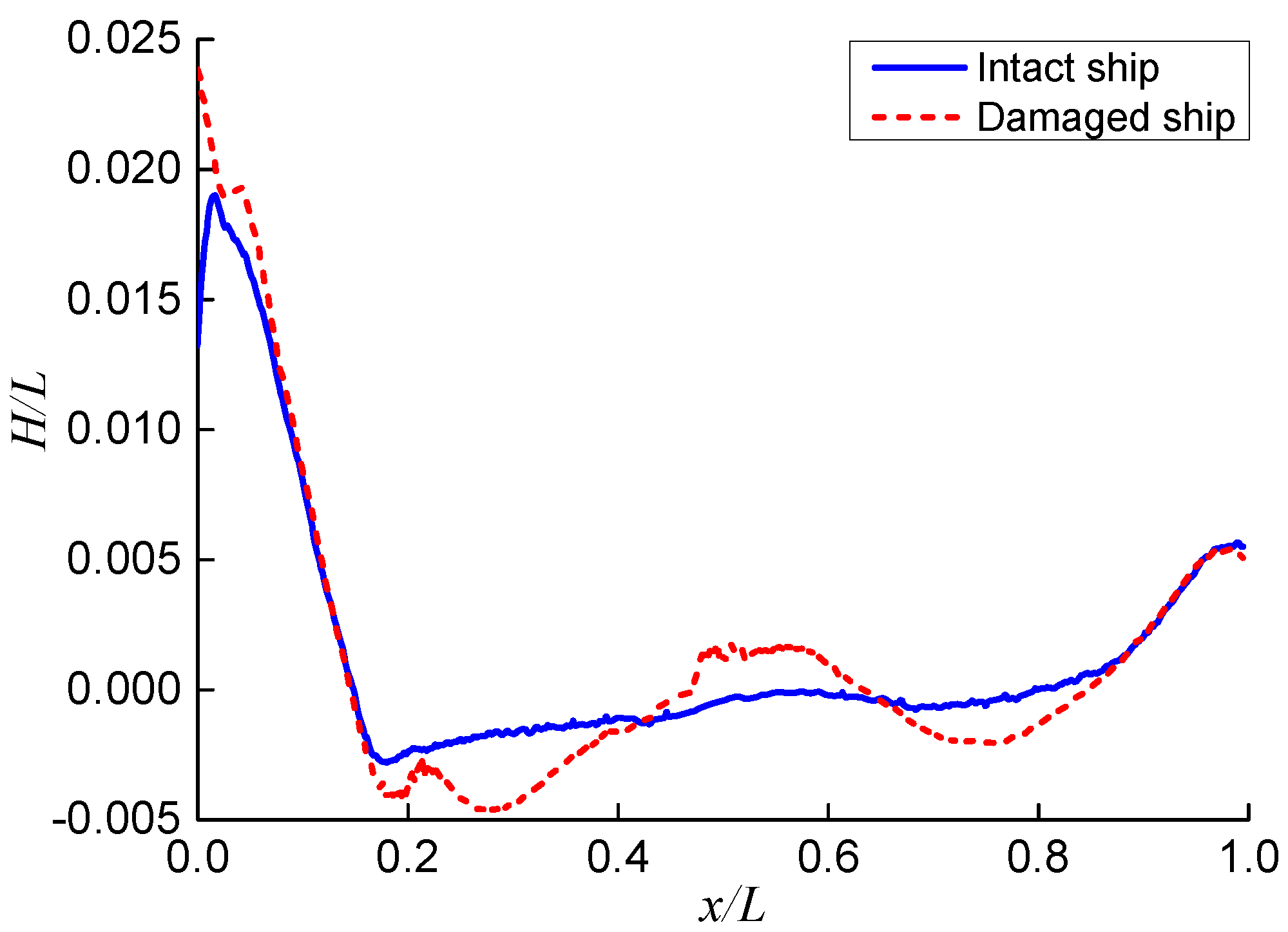
The total resistance of the ship is divided into frictional resistance and pressure resistance. Figure 12 and Figure 13 compare the resistance components of the ship for intact and symmetrical flooding cases. The floodwater will cause the ship to sink and increase the wet surface of the ship. Thus, both the frictional and pressure resistance of the damaged ship are larger than those of the intact ship. After the ship incurs damages, the pressure resistance increases from 56% to 150% at different forward speeds. The increase of pressure resistance is much greater than the increase of frictional resistance (7–10%). For the frictional resistance, it mainly depends on the wet surface of the hull. For Fr = 0.05~0.40, the wet surface of the external hull for damaged condition is 11% to 14% more than that of the intact condition. The frictional resistance of the damaged ship increases moderately. For the increased pressure resistance, it is partly caused by the changes of wave elevation on hull surface (see Figure 14). After the ship is damaged, its attitudes (draft, heel and trim) are changed. Since the draft increases significantly, the wave elevation on the hull surface for the damaged ship is larger than that of the intact ship, leading to the increase of pressure resistance due to a wave-making effect. In addition, water flowing through the opening and inside the compartments induces pressure resistance of the compartment (see Table 11). Compared with the intact ship, the proportion of pressure resistance in the total resistance increases by 17% to 89%, which indicates that the main component of the increased resistance for the ship under symmetrical flooding is the pressure resistance.
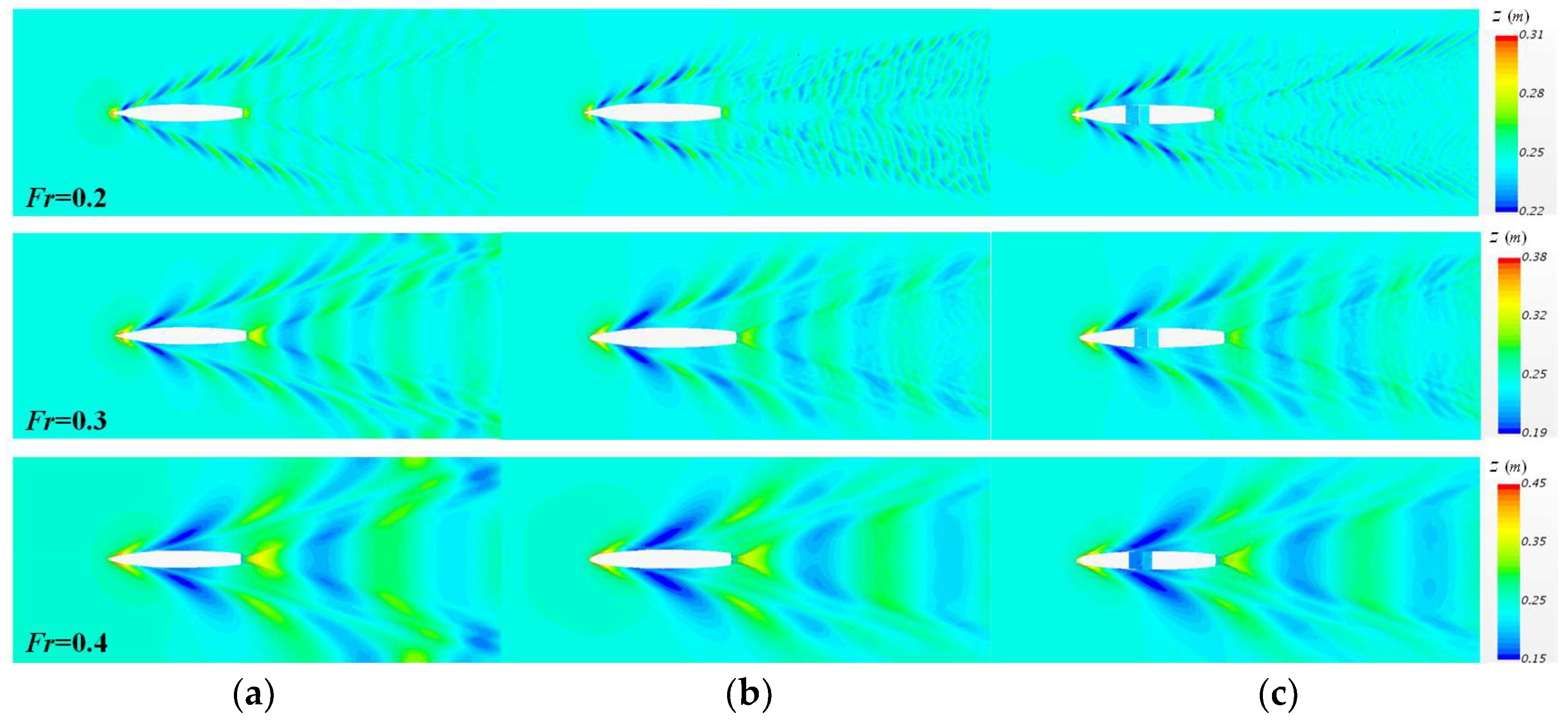
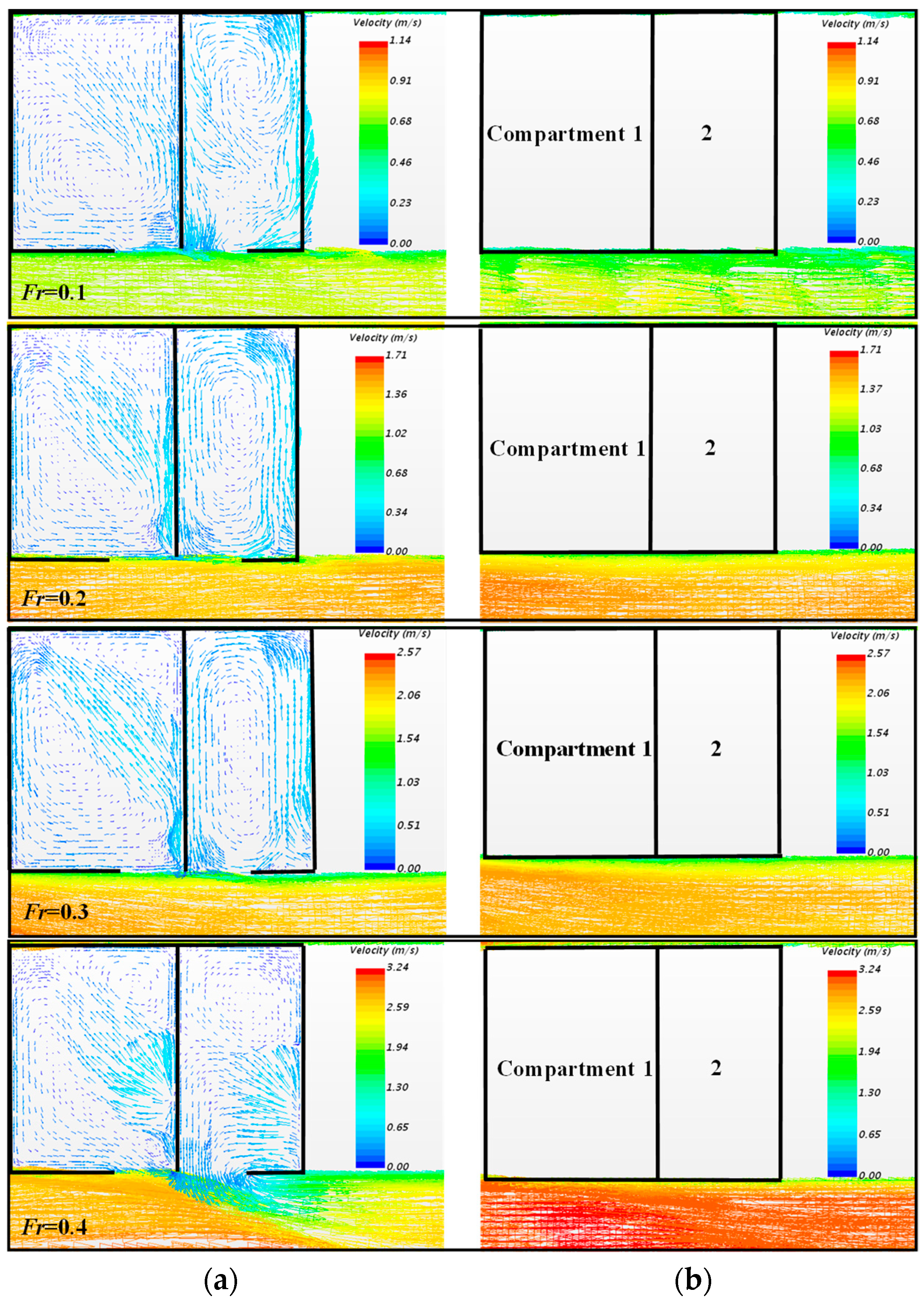
The characteristics of water flow around the ship and inside the compartments for the ship under symmetrical flooding are analyzed. The wave patterns for intact, symmetrical flooding and damage-repaired cases are presented in Figure 15. The wave patterns of the intact case are significantly different from the other two cases because of the smaller draught of the intact ship. Comparing the symmetrical flooding case with the damage-repaired case, the existence of a damaged opening only disturbs the wave pattern around the opening and has limited influence on the general wave pattern of the fluid domain. This influence decreases with the increase of the forward speed. Figure 16 compares the flow velocity near the damaged opening under the symmetrical flooding case and damage-repaired case. When the water flows into the compartments, stable backflow and vortex are formed. The water surface profile in the compartments remains constant for the same forward speed, as shown in Figure 17. For medium and low forward speeds (Fr ≤ 0.3), the water flow in the compartments varies slightly with the forward speed. The water surface is calm and the vortex motion is moderate. The flow velocity inside the compartments and near the damaged opening is smaller than that outside the ship. Thus, the changes of the flow patterns near the damaged opening have limited influences on the external flow field. For both the symmetrical flooding case and the damage-repaired case, the flow field in the area away from the damaged opening is similar. For a high-speed case (Fr = 0.4), water in the compartments collides with the wall violently and forms a notable reversed flow. The vortex profile and water surface in the compartments are changed greatly. The complex flow pattern near the opening has large interference on the flow velocity outside the ship. As a result, the velocity at the midship area for the symmetrical flooding case is different from that for the damage-repaired case. To illustrate the contribution of flow patterns inside and outside the compartments to the ship resistance, the ship resistance under symmetrical flooding is divided into compartment resistance and hull resistance, as summarized in Table 11. The compartment resistance accounts for 8.5% to 16.8% of the total resistance at different forward speeds and is dominated by the pressure resistance. With the increase of speed, the water vortex in the compartments becomes stronger. The compartment resistance increases. The hull resistance is the main component of the ship resistance under symmetrical flooding. With the increase of speed, the pressure resistance increases and becomes larger than the frictional resistance. The variation characteristics of hull resistance are basically consistent with that of total resistance.

4.2. Asymmetric Flooding

The resistance and attitudes of the ship under asymmetric flooding at different forward speeds (Fr = 0.1~0.4) are calculated using the CFD method. The principles of mesh and time arrangements are consistent with those of symmetrical flooding. The comparisons of the attitudes under symmetrical flooding and asymmetric flooding are listed in Table 12. The trim of the ship under symmetrical and asymmetric flooding is small at different forward speeds. The difference between two cases is approximately 0.3°. The sinkage gradually increases with the increase of forward speed. Compared with the symmetrical flooding case, the volume of the compartments for the asymmetric case is smaller, which causes an average decrease of 42% of ship draught at different forward speeds. Also, the asymmetric distribution of water in the compartments makes the heel angle increase by 15°. As discussed in Section 4.1, the change of draught is the main factor that influences the ship’s total resistance. Compared with the symmetrical flooding case, the total resistance of the ship under asymmetric flooding decreases due to the draught reduction. For the asymmetric flooding case at different forward speeds, the range of resistance increase is from 18% to 33%, which is lower than that of the symmetrical flooding case, as listed in Table 13.
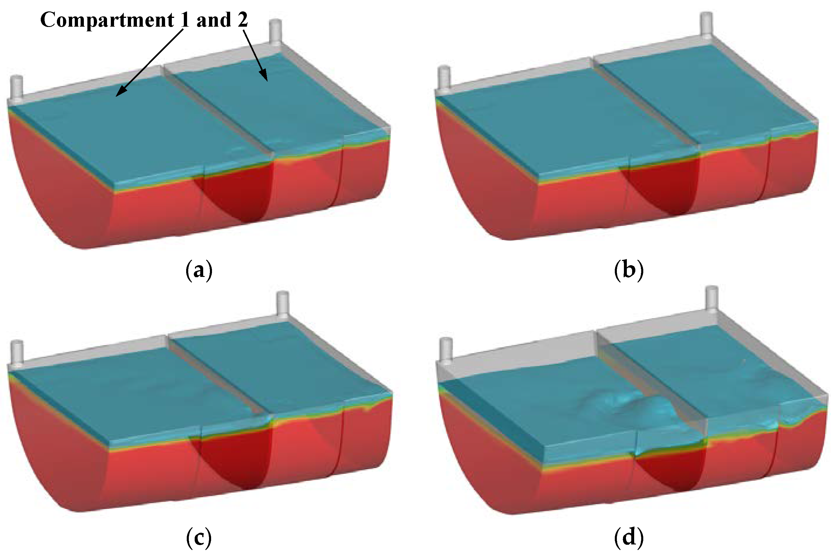
Figure 18 and Figure 19 depict the flow velocity and water profile in the compartments for the ship under asymmetric flooding at different forward speeds. Similar to the symmetrical flooding case (see Figure 16 and Figure 17), for the medium and low speeds (Fr ≤ 0.3), the asymmetric flooding cases present low flow velocity, gentle vortex motion and calm water surface. The impact of the damaged opening on the flow field outside the hull is limited. For the high-speed case (Fr = 0.4), the water in the compartments moves violently and causes great interference to the flow field outside the ship. For the asymmetric flooding case, the total resistance of the ship is decomposed into the compartment resistance and hull resistance, as summarized in Table 14. Similar to the symmetrical flooding case, the compartment and hull resistances in the asymmetric flooding case increase with the forward speed increases. The compartment resistance accounts for 12% to 20% of the total resistance at different forward speeds. The frictional resistance in the compartments can be ignored. The hull resistance is the main component of the total resistance for the ship under asymmetric flooding. For the hull resistance, the pressure resistance becomes larger than the frictional resistance as the speed increases. Compared with the intact case (see Figure 12 and Figure 13), the range of increased pressure resistance at different forward speeds for the ship under asymmetric flooding is from 47% to 126%, which is much larger than the increase of frictional resistance (0.1% to 3%). The proportion of pressure resistance in the total resistance increases from 17% to 82%. It indicates that the increase in resistance is dominated by the pressure resistance.

5. Conclusions

The RANS solver, which is based on the VOF method and dynamic overlapping grid technology, is applied to investigate the attitudes and resistance of the side-damaged frigate DTMB-5415 during the steady flooding phase. Based on the validated model of the intact ship, the flow field of the ship at different forward speeds is simulated for the intact, side-damaged (causing asymmetric and symmetrical flooding) and damage-repaired cases. The characteristics of the attitudes, resistance and the flow field inside the compartments and outside the ship are compared and analyzed for different cases. The main findings are summarized as follows.
  • For the side-damaged cases, the heel and trim of the ship at different forward speeds are similar to those in the zero-speed case. The main change of ship attitudes is that the sinkage gradually increases as the speed increases. The sinkage of the ship with forward speed is larger than that of the zero-speed ship. Compared with the symmetrical flooding case, due to the differences between the volume and distribution of water in the compartments, the sinkage of the ship under asymmetric flooding at different forward speeds decreases by an average of 42%, while the heel angle increases by about 15°.
  • Compared with the intact ship, the resistance of the ship under symmetrical flooding increases from 27% to 42% at different forward speeds. Water flooding causes the ship to sink. The increase of the hull wet surface causes the increase of the ship resistance at different forward speeds, which ranges from 19% to 34%. In addition, the existence of opening disturbs the flow field around the ship and makes the ship resistance increase from 6% to 13%. The resistance of the ship under asymmetric flooding is slightly lower than that of the ship under symmetric flooding. Compared with the intact ship, the resistance of the ship under asymmetric flooding increases from 18% to 33%.
  • Compared with the intact ship, the pressure resistance of the damaged ship at different forward speeds increases from 47% to 150%. The proportion of pressure resistance in the total resistance also increases from 17% to 89%. The main component of the increased resistance for the damaged ship is the pressure resistance.
  • During the steady flooding, the water movement in the compartments behaves as vortex flow. The profile of the internal water surface remains constant for the same forward speed. With the speed increases, the vortex flow in the compartments becomes complex. The water surface fluctuates significantly. Consequently, the compartment resistance increases. The proportion of compartment resistance in the total resistance ranges from 9% to 20% at different forward speeds.
The present study discusses the characteristics of ship’s attitudes and resistance with side damage occurring at mid-ship. In future work, the cases of ship with bow damage or stern damage will be investigated.

Author Contributions

This work was supervised by Z.G. The numerical simulations and the draft of the text were handled by W.X. The computational results were prepared and analyzed by S.X. All authors have read and agreed to the published version of the manuscript.

Funding

This research was supported by the National Natural Science Foundation of China (grant number 52071242).

Institutional Review Board Statement

Not applicable.

Informed Consent Statement

Not applicable.

Conflicts of Interest

The authors declare no conflict of interest.

References

  1. Marco, P.E.H.; Jeonghwa, S.; Hamid, S.H. Numerical simulations for the safe return to port of a damaged passenger ship in head or following seas. Ocean Eng. 2017, 143, 305–318. [Google Scholar]
  2. Zhang, X.L.; Mancini, M.; Lin, Z.; Li, P. Numerical investigation into the effect of damage openings on ship hydrodynamics by the overset mesh technique. J. Mar. Sci. Eng. 2020, 8, 11. [Google Scholar] [CrossRef] [Green Version]
  3. Acanfora, M.; Begovic, E.; Luca, F.D. A Fast simulation method for damaged ship dynamics. J. Mar. Sci. Eng. 2019, 7, 111. [Google Scholar] [CrossRef] [Green Version]
  4. Sadat-Hosseini, H.; Kim, D.H.; Carrica, P.M.; Rhee, S.H. URANS simulations for a flooded ship in calm and regular beam waves. Ocean. Eng. 2016, 120, 318–330. [Google Scholar] [CrossRef] [Green Version]
  5. Ermina, B.; Alexander, H.D.; Atilla, I.; Domenica, P. Roll damping assessment of intact and damaged ship by CFD and EFD methods. In Proceedings of the 12th International Conference on the Stability of Ships and Ocean Vehicles, Glasgow, UK, 13–19 June 2015. [Google Scholar]
  6. Song, S.; Ravenna, R.; Dai, S. Experimental investigation on the effect of heterogeneous hull roughness on ship resistance. Ocean Eng. 2021, 223, 108590. [Google Scholar] [CrossRef]
  7. Song, S.; Dai, S.; Demirel, Y.K. Experimental and theoretical study of the effect of hull roughness on ship resistance. J. Ship Res. 2021, 65, 62–71. [Google Scholar] [CrossRef]
  8. Niklas, K.; Pruszko, H. Full-scale CFD simulations for the determination of ship resistance as a rational, alternative method to towing tank experiments. Ocean Eng. 2019, 190, 106435. [Google Scholar] [CrossRef]
  9. Zhang, X.L.; Mancini, M.; Lin, Z.; Li, P. Numerical simulation of the ship resistance of KCS in different water depths for model-scale and full-scale. J. Mar. Sci. Eng. 2020, 8, 745. [Google Scholar]
  10. Linde, F.; Ouahsine, A.; Huybrechts, N.; Sergent, P. Three-Dimensional numerical simulation of ship resistance in restricted waterways: Effect of ship sinkage and channel restriction. J. Waterw. Port. Coastal. Ocean. Eng. 2017, 143, 06016003. [Google Scholar] [CrossRef]
  11. Ravenna, R.; Song, S.; Shi, W.C.; Sant, T. CFD analysis of the effect of heterogeneous hull roughness on ship resistance. Ocean Eng. 2022, 258, 111733. [Google Scholar] [CrossRef]
  12. Ali, M.A.; Peng, H.; Qiu, W. Resistance prediction of two fishing vessel models based on RANS solutions. Phys. Chem. Earth Parts A/B/C 2019, 113, 115–122. [Google Scholar] [CrossRef]
  13. Cucinotta, F.; Mancini, D.; Sfravara, F.; Tamburrino, F. The effect of longitudinal rails on an air cavity stepped planing hull. J. Mar. Sci. Eng. 2021, 9, 470. [Google Scholar] [CrossRef]
  14. Cucinotta, F.; Guglielmino, E.; Sfravara, F. A critical CAE analysis of the bottom shape of a multi stepped air cavity planing hull. Appl. Ocean Res. 2019, 82, 130–142. [Google Scholar] [CrossRef]
  15. Basic, J.; Degiuli, N.; Deihalla, R. Total resistance prediction of an intact and damaged tanker with flooded tanks in calm water. Ocean Eng. 2017, 130, 83–91. [Google Scholar] [CrossRef]
  16. Zhang, X.Y.; Sun, L.P.; Sun, C.; Wang, C. Study on the influence of the moonpool on the smooth water resistance performance of the ship. Ocean Eng. 2021, 237, 1–13. [Google Scholar] [CrossRef]
  17. Shi, X.; Chen, X.Q.; Tan, J.H. Study of resistance performance of vessels with notches by experimental and computational fluid dynamics calculation methods. J. Shanghai Jiaotong Univ. 2010, 15, 340–345. [Google Scholar] [CrossRef]
  18. Erik, H.; John, T. Effect of the Moonpool on the Total Resistance of a Drillship. Master’s Thesis, Chalmers University of Technology, Gothenburg, Sweden, 2012. [Google Scholar]
  19. Machado, L.; Fernandes, A.C.; Hussain, A.A. Effects on drillship resistance of a large moonpool using CFD simulations with experimental validation. In Proceedings of the ASME 2016 35th International Conference on Ocean, Offshore and Arctic Engineering, Busan, South Korea, 19 June 2016. [Google Scholar]
  20. Li, Y.Z.; Zhang, H.B. On flow field and additional resistance of moonpool in drillship with CFD. Ship Boat. 2015, 26, 10–15. [Google Scholar]
  21. Sivabalan, P. Influence of moonpool on the total resistance of a drillship by the effect of water motions inside the moonpool. Sustain. Mar. Struct. 2019, 1, 35–40. [Google Scholar]
  22. Ma, P.; Xing, X.; Yan, D. Drillship moonpool design to reduce added resistance for fuel saving. In Proceedings of the Offshore Technology Conference, Houston, TX, USA, 2–5 May 2016. [Google Scholar]
  23. Lee, S.K.; Xu, L. CFD Study and Model Test Verification of Moonpool Configuration Modifications for Minimizing Drillship Resistance. In Practical Design of Ships and Other Floating Structures, Proceedings of the 14th International Symposium, PRADS 2019, Yokohama, Japan, 22–26 September 2019; Springer: Singapore, 2019; pp. 3–27. [Google Scholar]
  24. Zhang, X.L.; Li, P.; Mancini, S. Numerical investigation into the resistance performance for the damaged DTMB 5415 ship in calm water and regular head waves. Ships Offshore Struct. 2021, 10, 1–12. [Google Scholar] [CrossRef]
  25. Zhang, X.L.; Lin, Z.; Li, P. A numerical investigation on the effect of symmetric and asymmetric flooding on the damage stability of a ship. J. Mar. Sci. Eng. 2020, 25, 1157–1165. [Google Scholar] [CrossRef]
  26. Gao, Z.; Wang, Y.; Su, Y. On damaged ship motion and capsizing in beam waves due to sudden water ingress using the RANS method. Appl. Ocean Res. 2020, 95, 102047. [Google Scholar] [CrossRef]
  27. Begovic, E.; Mortola, G.; Incecik, A.; Day, A.H. Experimental assessment of intact and damaged ship motions in head, beam and quartering seas. Ocean Eng. 2013, 72, 209–226. [Google Scholar] [CrossRef]
  28. Olivieri, A.; Pistani, F.; Avanzini, A.; Stern, F.; Penna, R. Towing Tank Experiments of Resistance, Sinkage and Trim, Boundary Layer, Wake, and Free Surface Flow around a Naval Combatant INSEAN 2340 Model; IIHR-TR-421; College of Engineering, The University of Iowa: Iowa City, IA, USA, 2001. [Google Scholar]
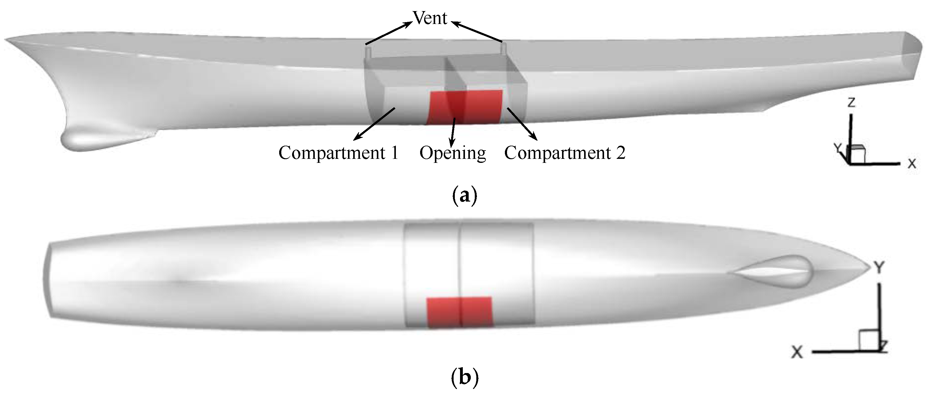
Figure 1. Model of frigate with damaged compartments for symmetrical flooding at different views: (a) Side view (b) Bottom view.
Jmse 10 01440 g001
Figure 2. Model of frigate with damaged compartments for asymmetric flooding: (a) Compartments (b) Ship.
Jmse 10 01440 g002
Figure 3. Sketch of the computational domain.
Jmse 10 01440 g003
Figure 4. Mesh arrangement for intact ship case (medium mesh).
Jmse 10 01440 g004
Figure 5. Y+ distribution on the hull for medium mesh.
Jmse 10 01440 g005
Figure 6. Comparison of wave elevation on hull surface obtained by computation and experiment for intact ship.
Jmse 10 01440 g006
Figure 7. Comparison of wave elevation at y/L = 0.082 longitudinal section obtained by computation and experiment for intact ship.
Jmse 10 01440 g007
Figure 8. Comparison of wave elevation at y/L = 0.172 longitudinal section obtained by computation and experiment for intact ship.
Jmse 10 01440 g008
Figure 9. Comparison of total resistance obtained by computation and experiment for intact ship at different forward speeds.
Jmse 10 01440 g009
Figure 10. Comparison of sinkage obtained by computation and experiment for intact ship at different forward speeds.
Jmse 10 01440 g010
Figure 11. Mesh arrangement for the case of ship under symmetrical flooding.
Jmse 10 01440 g011
Figure 12. Comparison of frictional resistance and its proportion to total resistance for the ship in intact and symmetrical flooding cases.
Jmse 10 01440 g012
Figure 13. Comparison of pressure resistance and its proportion to total resistance for the ship in intact and symmetrical flooding cases.
Jmse 10 01440 g013
Figure 14. Comparison of wave elevation on the hull surface for intact and damaged ships (Fr = 0.30).
Jmse 10 01440 g014
Figure 15. Comparison of wave patterns in different cases: (a) Intact case; (b) Damage-repaired case; (c) Symmetrical flooding case.
Jmse 10 01440 g015
Figure 16. Comparison of local flow for two cases: (a) Symmetrical flooding case; (b) Damage-repaired case.
Jmse 10 01440 g016
Figure 17. Comparison of water surface in compartments during symmetrical flooding at different forward speeds: (a) Fr = 0.1 (b) Fr = 0.2 (c) Fr = 0.3 (d) Fr = 0.4.
Jmse 10 01440 g017
Figure 18. Comparison of local flow for the ship under asymmetric flooding at different forward speeds: (a) Fr = 0.1 (b) Fr = 0.2 (c) Fr = 0.3 (d) Fr = 0.4.
Jmse 10 01440 g018
Figure 19. Comparison of water surface in compartments for the ship under asymmetric flooding at different speeds: (a) Fr = 0.1 (b) Fr = 0.2 (c) Fr = 0.3 (d) Fr = 0.4.
Jmse 10 01440 g019
Table 1. Main particulars of DTMB-5415.
Main ParticularsFull ScaleModel Scale (1/24.83)
Length of waterline (L) (m)142.05.719
Breadth of waterline (B) (m)19.060.768
Draft (T) (m)6.150.248
Displacement (Δ) (ton)8636.00.554
Vertical center of gravity from baseline (KG) (m)7.5550.304
Roll radius of gyration rxx (m)7.0520.284
Pitch radius of gyration ryy (m)35.51.429
Table 2. Properties of the damaged compartments.
Main PropertiesFull ScaleModel Scale (1/24.83)
Length of damaged opening (m)12.150.49
Height of damaged opening (m)7.690.31
Distance between front of compartment 1 and stern (m)65.662.645
Distance between end of compartment 1 and stern (m)76.353.077
Distance between end of compartment 2 and stern (m)90.023.626
Volume of compartment 1 (m3)15100.099
Volume of compartment 2 (m3)11890.078
Table 3. Three sets of mesh for intact ship case.
MeshNumber of MeshSize of Mesh Near the Free Surface in Three DirectionsThickness of the First Cell Near the Hull SurfaceY+ on the Hull Wet Surface
xyz
Fine6.52 million0.028 m0.028 m0.007 m0.0015 m40~120
Medium3.48 million0.04 m0.04 m0.01 m
Coarse2.54 million0.057 m0.057 m0.014 m
Table 4. Total resistance, sinkage and trim obtained by three sets of mesh for intact ship (Fr = 0.28).
MeshTotal Resistance (N)Sinkage (m)Trim (°)
Num.Exp.Error (%)Num.Exp.Error (%)Num.Exp.Error (%)
Fine44.6144.50+0.2−0.0116−0.0104+11.5−0.457−0.108+323
Medium44.77+0.6−0.0116+11.5−0.460+326
Coarse44.98+1.1−0.0117+12.5−0.464+330
Table 5. Results of grid dependence study for intact ship (Fr = 0.28).
VariableRGPGδRECGUGUG (D%)
Resistance0.760.780.510.310.511.14
Table 6. Total resistance, sinkage and trim obtained by three time steps for intact ship (Fr = 0.28).
Timesteps (s)Total Resistance (N)Sinkage (m)Trim (°)
Num.Exp.Error (%)Num.Exp.Error (%)Num.Exp.Error (%)
0.002545.4144.50+2.0−0.0114−0.0104+9.6−0.456−0.108+322
0.00545.18+1.5−0.0115+10.6−0.457+323
0.0144.77+0.6−0.0116+11.5−0.460+326
Table 7. Results of time dependence study for intact ship (Fr = 0.28).
VariableRTPTδRECTUTUT (D%)
Resistance0.560.83−0.290.260.290.65
Table 8. Results of three different mesh sizes inside the compartment for damaged ship (Fr = 0.30).
Mesh Sizes (m)Number of Mesh Inside the CompartmentResistance (N)
0.01430,99776.28
0.0187,67576.42
0.007247,98276.72
Table 9. The comparison of attitudes in intact and symmetrical flooding cases at different forward speeds.
FrSinkage (m)Trim (°)Heel (°)
IntactSymmetrical FloodingIntactSymmetrical FloodingSymmetrical Flooding
0.000.0−0.052−0.31−0.710.60
0.05−0.001−0.056−0.32−1.060.59
0.10−0.002−0.057−0.33−1.070.59
0.15−0.003−0.058−0.36−1.100.59
0.20−0.006−0.061−0.39−1.150.58
0.25−0.008−0.064−0.43−1.180.58
0.30−0.014−0.070−0.44−1.210.58
0.35−0.019−0.071−0.45−1.190.62
0.40−0.026−0.073−0.14−0.820.39
Table 10. The comparison of total resistance in intact, damage-repaired and symmetrical flooding cases at different forward speeds (unit: N).
FrIntactDamage-Repaired (Increased Ratio)Symmetrical Flooding (Increased Ratio)
0.051.551.85 (19%)1.97 (27%)
0.105.436.50 (20%)7.03 (29%)
0.1511.3413.56 (20%)15.03 (33%)
0.2021.4425.49 (19%)27.90 (30%)
0.2534.1643.09 (26%)46.16 (35%)
0.3054.2472.49 (34%)76.42 (41%)
0.3579.52105.42 (33%)112.98 (42%)
0.40133.32171.03 (28%)178.32 (34%)
Table 11. Resistances of compartment and hull and proportions to the total resistance under symmetrical flooding (unit: N).
FrCompartmentHull
Frictional Resistance
(Proportion)
Pressure Resistance
(Proportion)
Frictional Resistance
(Proportion)
Pressure Resistance
(Proportion)
0.050.001 (0.1%)0.17 (8.6%)1.43 (72.5%)0.37 (18.8%)
0.100.01 (0.1%)0.71 (10.1%)4.90 (69.7%)1.41 (20.1%)
0.150.01 (0.1%)1.68 (11.2%)10.21 (67.9%)3.13 (20.8%)
0.200.02 (0.1%)3.03 (10.9%)18.65 (66.8%)6.20 (22.2%)
0.250.05 (0.1%)7.71 (16.7%)27.65 (59.9%)10.75 (23.3%)
0.300.08 (0.1%)9.01 (11.8%)38.83 (50.8%)28.50 (37.3%)
0.350.22 (0.2%)11.84 (10.5%)51.27 (45.4%)49.65 (43.9%)
0.400.25 (0.1%)14.95 (8.4%)65.54 (36.8%)97.58 (54.7%)
Table 12. The comparison of ship attitudes under symmetrical flooding and asymmetric flooding.
FrSinkage (m)Trim (°)Heel (°)
Symmetrical FloodingAsymmetric FloodingSymmetrical FloodingAsymmetric FloodingSymmetrical FloodingAsymmetric Flooding
0.00−0.052−0.028−0.71−0.770.6015.71
0.10−0.057−0.031−1.07−0.780.5915.87
0.20−0.061−0.033−1.15−0.850.5815.52
0.30−0.070−0.040−1.21−0.890.5815.25
0.40−0.073−0.051−0.82−0.560.3912.73
Table 13. The comparison of ship total resistance in the intact, symmetrical flooding and asymmetric flooding cases (unit: N).
FrIntactAsymmetric Flooding (Increased Ratio)Symmetrical Flooding (Increased Ratio)
0.105.436.73 (24%)7.03 (29%)
0.2021.4425.34 (18%)27.90 (30%)
0.3054.2472.07 (33%)76.42 (41%)
0.40133.32167.27 (25%)178.32 (34%)
Table 14. Resistances of compartment and hull and proportions to the total resistance under the asymmetric flooding case (unit: N).
FrCompartmentHull
Frictional Resistance
(Proportion)
Pressure Resistance
(Proportion)
Frictional Resistance
(Proportion)
Pressure Resistance
(Proportion)
0.100.01 (0.1%)0.88 (13.1%)4.62 (68.5%)1.24 (18.4%)
0.200.02 (0.1%)3.67 (14.5%)16.91 (66.7%)4.74 (18.7%)
0.300.06 (0.1%)14.23 (19.7%)35.78 (49.7%)22.00 (30.5%)
0.400.03 (0.1%)20.84 (12.5%)61.74 (36.9%)84.66 (50.6%)
Publisher’s Note: MDPI stays neutral with regard to jurisdictional claims in published maps and institutional affiliations.