Abstract
The gyrostabilizer produces the anti-roll effect through the precession output moment generated by a high-speed rotating flywheel. As a floating-base multi-body system composed of ship and gyrostabilizer, the recent research that has only focused on the control strategies or multi-body dynamics is obviously not comprehensive. This study presents an adaptive controller based on the variable gain control strategy for a marine gyrostabilizer installed on a port salvage tug. The variable gain control strategy controlled the flywheel precession output moment of the gyrostabilizer and thereby of the precession process, to reduce the ship roll motion effectively. Furthermore, a full-system hydrodynamic model of a gyrostabilizer-ship-wave based on three-dimensional numerical wave flume technology was innovatively established to evaluate its anti-roll performance under irregular wave conditions. The simulation results show that, for the sea state considered, the increase of spin rate of gyrostabilizer flywheel improved the anti-roll effect significantly. The average anti-roll rate of the gyrostabilizer decreased with the increase of significant wave height, wave period and wave encounter angle.
1. Introduction
Ships sailing and operating at sea are constantly affected by wind, waves and currents. These lead to continuous swaying motions of ship, including roll, pitch and yaw. These irregular undesirable motions always have adverse effects on the stability, seakeeping and resistance characteristic of ship [1,2], which will eventually affect the safety of navigation, anchoring and operations of ships, as well as the cargo stowage, the comfort of occupants and the normal operation of mechanical equipment [3]. The damage caused by ship roll needs special attention, especially for the special ships with high stability requirements, such as military ships, crane ships, passenger ships and rescue ships [4].
In order to minimize the roll motion of ship, many researchers and marine equipment companies have developed various types of ship stabilization technologies and devices. The most notable ones include bilge keel, fin stabilizer, rudder roll damping, anti-roll tank and anti-roll gyrostabilizer [5]. According to the installation location, these devices can be classified into two types: external device and internal device. The external devices are installed on the outside of the hull, which can generate anti-roll force and moment to the ship through the hydrodynamic interaction between the anti-roll attachment and the water; the bilge keel, fin stabilizer and rudder roll damping belong to this type [6]. The internal devices are usually installed inside the ship, which achieve the purpose of ship anti-roll by generating roll damping force and moment of the device itself. The most typical internal devices are anti-roll tanks and gyrostabilizer [7].
The marine gyrostabilizer reduces the ship swaying motion by the damping moment generated by the precession effect of the high-speed rotating flywheel. The first marine gyrostabilizer was a passive device, which was invented by Otto Schlick in Germany in 1904. In 1911, Sperry Company of the United States improved the passive gyrostabilizer into an active device by adding a forced action to the gyro frame. This device was installed on a yacht in 1915. The test results showed that the device has good anti-roll effect [8].
Compared with the external anti-roll devices, the gyrostabilizer has no external attachment and additional resistance. Therefore, the ship has better anti-roll performance in all speed range. Moreover, the weight and volume of the gyrostabilizer are very small, and the operation is simpler and safer. Its anti-roll effect is usually better with no impact on the stability of the ship [9]. What deserves attention is that the gyrostabilizer is especially suitable for installation on existing ships flexibility. However, for a long time, the marine gyrostabilizer has not been widely used for its complicated structure and high cost. In recent years, with the application of new technologies, new materials and the progress of manufacturing technology, the marine gyrostabilizer technology has received renewed attention [10].
The research of marine gyrostabilizer mainly includes dynamic simulation, system control and device experiment. For the dynamic simulation of marine gyrostabilizer, the most commonly used method is to establish a mechanical dynamic model reflecting the motion and interaction of the gyrostabilizer and ship. The ship motion on waves is represented by the model equations. The disturbance items are adopted to represent the wave excitation force and excitation moment acting on ship. However, in the specific solution of model equations, the fluid mechanics equations based on potential flow theory for rigid body are usually not easy to solve. Therefore, the hydrodynamic parameters in the model equations are generally replaced by empirical values or approximate values that obtained from the ship model tests or full-scale ship experiment. The principle of this method is easy to understand and the calculation process is relatively simple. However, because of the selection of empirical data and experimental data, its accuracy is insufficient. This method is difficult to deal with some ships or floating bodies with complex geometric shapes. In most equations of ship motion in waves, there are generally no physical quantities used to represent the hydrodynamic effect of the underwater attachment structures of the ship. For example, the specific impacts of the rudder, propeller and other underwater attachment structures on ship are unavailable in many researches of the ship nonlinear motion [11,12,13].
The system control research mainly focuses on the design of control strategy for the regulating system of gyrostabilizer, which is also based on the model equations of ship motion [14]. In these studies, many effective control strategies have been proposed [15,16]. However, many designs of the control strategy are too complex and the types of gyrostabilizers are diverse, which limits its practical application in industrial products [17].
The sea trials and wave tank experiment of the device model are the most effective methods for the development of marine stabilization system [18]. However, the disadvantages of high cost, long time and test data susceptible to uncertainties are not conducive to the convenient design and research on working characteristics of the device.
In this research, a vertical axis gyrostabilizer installed on a port salvage tug was used as the study object. As a prerequisite for use on ships, an adaptive controller based on the variable gain control strategy was applied to design its controller. Then a full-system hydrodynamic model of gyrostabilizer-ship-wave was established to analyze the performance of the gyrostabilizer more comprehensively. The numerical simulation was based on the complex technologies of three-dimensional numerical wave tank and multi-floating body coupling. The hydrodynamic simulation results reflect the dynamic response of the gyrostabilizer, and the effects of wave conditions, gyrostabilizer flywheel momentum and flywheel working parameters on the anti-roll performance were obtained.
2. Research Object
The main structure of the vertical axis gyrostabilizer was composed of the fixed part and rotating part, which is shown in Figure 1. The structure size of the physical model refers to the GSZR-250K gyrostabilizer. The fixed part included a machinery bed, a shell, an outer support, a motor and other auxiliary equipment. The rotating body was mainly a cylindrical gyro flywheel. The machinery bed and other fixed parts were connected with the ship deck through many tie rods. The anti-roll moment generated by the high-speed rotating flywheel was transmitted to the entire hull through the fixed part of the marine gyrostabilizer and the damping unit, and, finally, inhibited the ship roll in the waves.
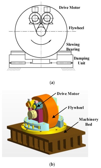
Figure 1.
Physical model of the marine gyrostabilizer. (a) Project drawing; (b) Assembly drawing.
The main parameters of the gyrostabilizer flywheel are shown in Table 1.

Table 1.
Major parameters of the marine gyrostabilizer flywheel.
Considering the applicability of this specification of the gyrostabilizer on the ship, a 3200HP salvage tug serving in Jingtang harbour district of China Tangshan port is used as the installation object for the gyrostabilizer. The main parameters of the ship are shown in Table 2.
Table 2.
Dimensions of ship for simulation.
The simulation model of ship-gyrostabilizer is shown in Figure 2. The gyrostabilizer was installed on the main deck of the ship. The vertical distance from the flywheel center to the bow was 20 m, and from the main deck was 0.75 m.
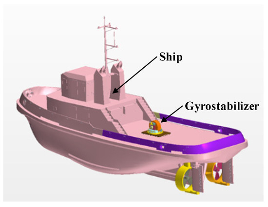
Figure 2.
Physical simulation model of ship-gyrostabilizer.
3. Roll Motion Equations and Anti-Roll Mechanism
The roll amplitude of ship is the most significant among the three rotational motion modes. Moreover, under the severe sea conditions, the excessive roll angle and beam wave have the most serious impact on the safety of the ship. Therefore, the characteristics of ship roll motion are one of the important indicators to evaluate the performance of ship [19].
In this paper, a mathematical model of ship roll motion with gyrostabilizer is established to explain its anti-roll principle [20].
where is the rotational inertia of ship roll motion including fixed parts of gyrostabilizer. is the additional mass moment of inertia of ship roll motion including fixed parts of the gyrostabilizer. is the roll angular displacement of the ship. is the roll damping moment of water on the ship. is the restoring moment of ship roll motion. is the wave excitation moment, which reflects the fluid-solid coupling between the wave and the hull. is the applied moment of gyrostabilizer on ship roll motion, which reflects the solid-solid coupling between the ship and the gyrostabilizer.
The roll amplitude of this type of tug sailing in the sheltered water is generally not more than 10°. When , is an approximate representation as a linear function of the roll angular velocity and is approximately expressed as a linear function of the roll angle.
where D is the weight of ship and gyrostabilizer fixed parts, h is the metacentric height of the ship.
The output moment of gyrostabilizer on ship roll motion R is expressed as:
where β is precession angle of gyrostabilizer flywheel and θ is the spin rate of the gyrostabilizer flywheel (rad/s).
Wave excitation moment is expressed as a function of effective wave slopes , which is:
In order to simplify the calculation process of the control equations, the linear wave assumption was applied, that is:
where is maximum significant wave slopes and ω is wave circular frequency. The Equation (1) is derived as:
4. Control Rate Design and Analysis
4.1. Control Rate Design
The real sea waves are irregular waves, and the ship performs irregular non-linear roll motion under the excitation of the waves. It is necessary to ensure that the gyrostabilizer automatically adapts to the different roll amplitudes and motion states of the ship. The variable gain control rate is one of the appropriate strategies to control the precession of the gyrostabilizer and suppress the roll amplitude of the ship in waves for its simple and direct features.
The precession output moment of the gyrostabilizer R is listed by Equation (4). The precession angle adopts the following control rate [20]:
where α is the control standard parameter, χ is the feedback gain of precession angle, and γ is the variable control gain.
Under the action of the gyrostabilizer damping units, the precession angular velocity of the flywheel is generally designed to be proportional to the roll angular velocity of the ship and inversely proportional to the precession angle. Therefore, for a specific sea condition, the maximum roll angle displacement of ship is defined as:
When the precession angle of the flywheel reaches its maximum , the following equation is obtained:
This control rate controlled the precession angle of flywheel in a reasonable range and made the output moment of the gyrostabilizer R opposite to the roll motion direction of the ship so as to produce the anti-roll effect.
The variable control gain was divided into five levels according to the change of the roll angular velocity of ship, which is shown in Table 3. The maximum roll angular velocity is defined as:
Table 3.
Design Parameters of the variable gain controller.
The length of time was chosen to be a constant slightly larger than the ship roll period.
The selection rule of the variable control gain γ should satisfy the following equation:
where, , C is a constant. This equation indicates that the increment of flywheel precession moment is a constant value when it changes between adjacent control levels.
The system control equation of ship and gyrostabilizer is expressed as:
where ,
In addition, in order to evaluate the anti-roll performance of gyrostabilizer more accurately, the following equation was used to define the average anti-roll rate .
where and are the average roll amplitudes with zero flywheel rate spin rate and with gyrostabilizer work respectively.
4.2. Calculation and Analysis
In this calculation, the wave period T was 3.0 s (ω = 2.094 rad/s), the ship’ forward speed was assumed to be zero, and the wave encounter angle was assumed to be 90° (beam waves). The control standard parameter was and the feedback gain of precession angle was . The variable control gain and roll angular velocity response were selected according to Table 4.
Table 4.
Variable control gain.
, and are set as the initial conditions for calculation. The system control equation of ship and gyrostabilizer are solved by the Runge–Kutta algorithm on the MATLAB platform.
Figure 3a–c are the time-domain curves of the ship roll angular displacement with wave height of 0.5 m, 1.5 m and 2.5 m. In the simulation calculation, the gyrostabilizer was set to be put into operation in the time range of 100 s to 200 s.
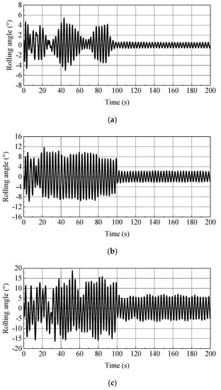
Figure 3.
Time-series roll motion of ship. (a) H = 0.5 m; (b) H = 1.5 m; (c) H = 2.5 m.
Based on the time-series roll motion of ship shown in Figure 3, the obtained anti-roll parameters are shown in Table 5.
Table 5.
Anti-roll parameters of the gyrostabilizer.
From the calculation result of the average anti-roll rate, it can be seen that the gyrostabilizer has shown good anti-roll performance in a variety of sea conditions. The method of using a variable gain controller to control the flywheel precession moment of this gyrostabilizer can make full use of the precession characteristics so that the gyrostabilizer can automatically adapt to different sea conditions and ship roll states.
5. Hydrodynamics Numerical Simulation
5.1. Numerical Simulation Method
The motion analysis of a ship equipped with gyrostabilizers under wave excitation should essentially be classified as a fluid–solid coupling dynamic analysis of a floating-base multi-body system. The gyrostabilizer exerted an influence on the ship through the interaction of their forces and moments. In this study, the finite element analysis software of STAR-CCM+ was used in the modeling and numerical simulation. The DFBI (dynamic fluid body interaction) motion model with six degrees of freedom was adopted to describe the ship motion in waves [21,22]. The interaction between the flywheel of the gyrostabilizer and the ship was described by the effect of rotary joint and linear damper of DFBI multi-body coupling model.
The feature of the large motion range of the ship and gyrostabilizer makes it necessary for the flow field near the free surface to have a high mesh precision in the multiphase flow simulation. In this paper, the overset mesh method and dynamic mesh technique were used to solve the problem of automatic grid generation of the moving boundary [23,24]. The VOF method (Volume of Fluid) was used to capture the interface of the two-phase flow.
In the full-system coupling physical model of the wave-ship-gyrostabilizer, the anti-roll effect of gyrostabilizer was mainly achieved through the solid-solid coupling between the gyrostabilizer flywheel and the ship, and the fluid-solid coupling between the waves and the ship.
In the specific implementation of the hydrodynamic simulation, the field functions of the initial conditions were used to constrain the maximum precession angle of the flywheel and the damping characteristics of the damping unit so as to realize the adaptive control characteristics of the gyrostabilizer.
5.2. Numerical Simulation Model and Verification
In order to make the numerical simulation results consistent with the real situation and the real ship, in the ship simulation model (Figure 2), the profile, rudder, propeller and bilge keel that affect the ship motion characteristics were the same as the actual target ship.
A three-dimensional numerical wave flume was established. The overset mesh method was applied in the mesh generation of the calculation domain, and the mesh of the wave surface was densified. As shown in Figure 4, the size of the calculation domain was 200 m × 100 m × 32 m. The origin O of the coordinate system was located at the center of the plane where the ship designed draft line. The water depth was 16m, which is consistent with the water depth of the sea area where the tug works in the Jingtang harbour district. The Pierson Moskowitz (PM) irregular wave spectrum was used in the calculation.
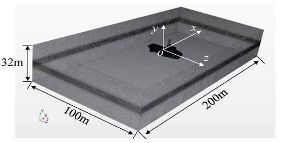
Figure 4.
Mesh of computational domain.
Figure 5 shows the scalar figure of the tug ship with a gyrostabilizer in the numerical simulation. The impact of ship speed was not considered for the time being; only the gyrostabilizer stabilizing effect was discussed when the ship was at anchor with zero forward speed.
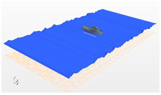
Figure 5.
Scalar figure of the tug ship with a gyrostabilizer in the numerical simulation.
In numerical simulation, the frictional resistance of the flywheel spinning and the interaction effect of the yaw and roll were ignored.
The mesh independence and step-length independence were verified for numerical simulation to ensure the credibility of the simulation results. The time step was calculated by the following equation.
where is the number of wave surface mesh nodes within one wave length.
The mesh convergence analysis is shown in Figure 6. It can be seen that, when the main mesh size was less than 0.75 m, the roll amplitude of the ship basically no longer changed. In this paper, the main mesh size selected in the calculation was 0.5 m, which meets the requirement of convergence.
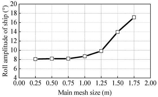
Figure 6.
Mesh convergence analysis.
In addition, the roll motion numerical results of the ship simulation model without the gyrostabilizer were compared with the sea trial data of the actual ship under the same working conditions. When the significant wave height was 1.5 m and the period T was 4.0 s, the time-series roll motion of the actual ship roll motion and beam waves are shown in Figure 7 and Figure 8 respectively.
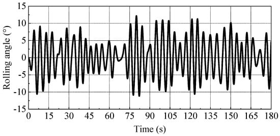
Figure 7.
Time-series roll motion of the actual ship with zero forward speed in beam waves.
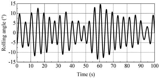
Figure 8.
Time-series roll motion obtained by numerical simulation.
It can be seen that the roll motion period of the ship in waves was consistent with the wave period. The average roll amplitude of the actual ship was 7.82° and the average roll amplitude of the simulation was 8.10°, with an error of about 3.6%, which shows that the numerical simulation result had good coherence with the data obtained by the actual ship test. Thus, it was verified that the numerical model and numerical simulation method are reliable.
5.3. Results and Analysis
5.3.1. Effect of Flywheel Spin Rate
Gyrostabilizer flywheel spin rates can significantly influence system performance. Generally, the rotational inertia of the flywheel is given; faster spin rates can enable the moment of momentum increase, which affects the stabilization of the gyrostabilizer to the ship. Figure 9 shows the time-series roll motion of the ship for varying flywheel spin rates (n = 0 r/min, n = 1000 r/min, n = 2000 r/min and n = 3000 r/min). Figure 10 shows the average roll amplitude of the ship and average anti-roll rate for varying flywheel spin rates (the percentage values marked on the curve are the corresponding anti-roll rates under these working conditions). The wave encounter angle was 90°, the significant wave height was 1.5 m and the wave period was 4.0 s. It can be seen that, with the increase of the flywheel speed, the average roll amplitude of the ship continued to decrease and the average anti-roll rate calculated by Equation (14) continued to increase. When the flywheel speed reached the rated speed of 2000 r/min, the average roll amplitude of ship is 2.9°, and the average anti-roll rate is 64.2%.
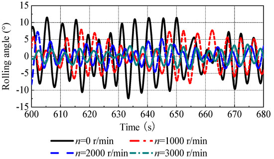
Figure 9.
Time-series roll motion of ship for varying flywheel spin rates.
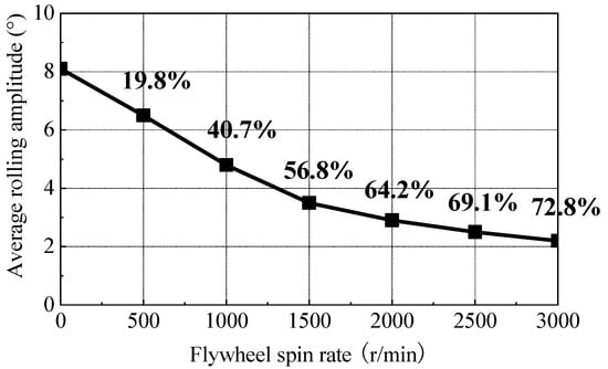
Figure 10.
Average roll amplitude of the ship and average anti-roll rate for varying flywheel spin rates.
5.3.2. Effect of Significant Wave Height
Figure 11a–c are the time-series roll motion of the ship for varying significant wave heights (, and ), with the wave period of 4.0 s, under the conditions of the gyrostabilizer working (n = 2000 r/min) and the gyrostabilizer not working (n = 0 r/min). The time-series roll motion of the ship for a significant wave height of 1.5 m is shown in Figure 8. Figure 12 shows the average roll amplitude of the ship for varying significant wave heights.
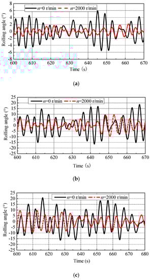
Figure 11.
Time-series roll motion for varying significant wave heights. (a) ; (b) ; (c) .
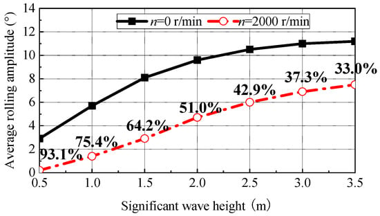
Figure 12.
Average roll amplitude of the ship and average anti-roll rate for varying significant wave heights.
It can be seen that the gyrostabilizer could significantly reduce the roll of the ship in waves within the range of significant wave height selected in this research. When the flywheel speed was constant, the average anti-roll rate decreased with the increase of significant wave height.
5.3.3. Effect of Wave Period
Figure 13a–c are the time-series roll motion for varying wave periods (T = 2.0 s, T = 3.0 s and T = 5.0 s) under the conditions of the gyrostabilizer working (n = 2000 r/min) and the gyrostabilizer not working (n = 0 r/min). Figure 14 shows the average roll amplitude of the ship and average anti-roll rate for varying wave periods. The significant wave height was 1.5 m.
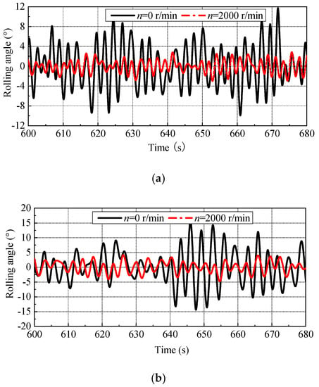
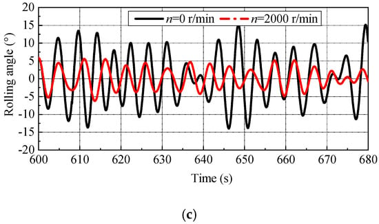
Figure 13.
Time-series roll motion for varying wave periods. (a) T = 2.0 s; (b) T = 3.0 s; (c) T = 5.0 s.
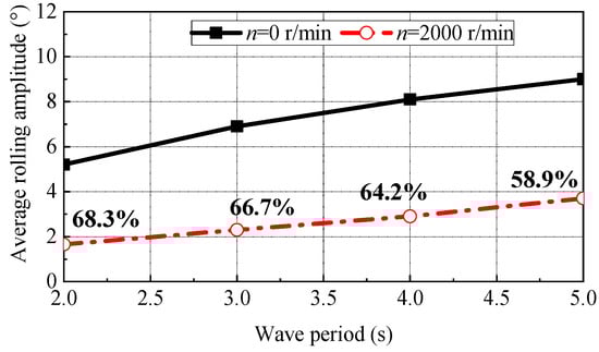
Figure 14.
Average roll amplitude of the ship and average anti-roll rate for varying wave periods.
It can be seen that the gyrostabilizer exhibited good anti-roll characteristics at each wave period. The average anti-roll rate decreased with the increase of the wave period. That is, in waves with a smaller period, the gyrostabilizer could usually play the better stabilization effect.
All simulations are carried out in irregular wave for significant wave height of 1.5 m and wave period of 4.0 s.
5.3.4. Effect of Wave Encounter Angle
Figure 15a,b are the time-series roll motion for varying wave encounter angles (μ = 30°, μ = 60° and μ = 90°) under the conditions of the gyrostabilizer working (n = 2000 r/min) and the gyrostabilizer not working (n = 0 r/min). Figure 16 shows the average roll amplitude of the ship and average anti-roll rate for varying wave encounter angles. The significant wave height was 1.5 m and the wave period was 4.0 s.
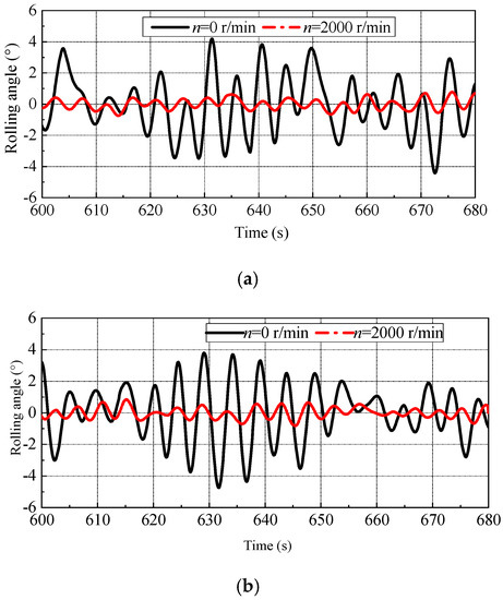
Figure 15.
Time-series roll motion for varying wave encounter angles. (a) μ = 30°; (b) μ = 60°.
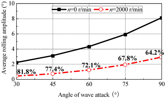
Figure 16.
Average roll amplitude of the ship and average anti-roll rate for varying wave encounter angles.
It can be seen that when the wave encounter angle increased from 30° to 90°, the roll amplitudes of the ship increased from 2.2° to 8.1° without roll stabilization. The roll amplitude was reduced from 0.4° to 2.9° under the stabilization effect of the gyrostabilizer. The reduction of roll amplitude continued to increase from 1.8° to 5.2°. However, the average anti-roll rate decreased from 81.8% to 64.2%.
6. Conclusions
This study presented an adaptive controller for a marine gyrostabilizer installed on a harbor tug and conducted a simulation study on its anti-roll performance. Furthermore, a full-system hydrodynamic model of gyrostabilizer-ship-wave based on three-dimensional numerical wave flume was established, and the working performance of the gyrostabilizer is studied. For various simulations carried out in this paper, the variable gain control strategy by restricting the precession angles and, thus, the precession output moment of the flywheel, could be applied to the vertical axis gyrostabilizer to reduce the ship roll motion effectively. The gyrostabilizer could improve its anti-roll performance significantly on ships by increasing the flywheel spin rate. Typically, the flywheel operates at the rated spin rate in a gyrostabilizer system. As the sea state changes, the stabilization performance of the gyrostabilizer showed a significant difference. Through the hydrodynamic simulations, it was found that the average anti-roll rate of the gyrostabilizer decreases with the increase of significant wave height, wave period and wave encounter angle. The gyrostabilizer systems provided an effective means of motion control for ships in waves. For gyrostabilizer systems to fulfill their potential, further studies regarding the system design and control would be worthwhile.
Author Contributions
Conceptualization, B.L.; Data curation, B.L.; Formal analysis, B.L.; Investigation, B.L.; Project administration, B.L. and N.C.; Resources, J.W. and N.C.; Software, J.W.; Supervision, X.Z.; Writing—original draft, B.L.; Writing—review and editing, X.Z. All authors have read and agreed to the published version of the manuscript.
Funding
This research was supported by the Scientific Research Initializing Fund of Jiangsu University of Science and Technology (Jiangsu University of Science and Technology, funding numbers 1142931705), the Open Fund of Zhenjiang Marine Power Equipment Characteristic Key Laboratory (Zhenjiang Marine Power Equipment Characteristic Key Laboratory, funding numbers 10331910), Jiangsu Enterprise Science and Technology Vice-General Talent Project (Jiangsu Province Department of Science and Technology, Jiangsu, China, funding numbers FZ20210894), and Jiangsu Natural Science Foundation (Jiangsu Province Department of Science and Technology, Jiangsu, China, funding numbers BK20210883).
Institutional Review Board Statement
Not applicable.
Informed Consent Statement
Not applicable.
Data Availability Statement
The data that support the findings of this study are available from the corresponding author upon reasonable request.
Acknowledgments
The authors extend their thanks to Tangshan Maritime Safety Administration of the People’s Republic of China for the help to provide measured data of the salvage tug.
Conflicts of Interest
The authors declare no conflict of interest. The funders had no role in the design of the study; in the collection, analyses, or interpretation of data; in the writing of the manuscript, or in the decision to publish the results.
Glossary
| Rotational inertia | |
| Added mass moment of inertia | |
| Roll angular displacement of ship | |
| Roll damping moment | |
| Restoring moment of ship roll motion | |
| Wave excitation moment | |
| Precession output moment of gyrostabilizer | |
| Weight of ship and gyrostabilizer | |
| Metacentric height of ship | |
| Precession angle of gyrostabilizer flywheel | |
| Spin rate of gyrostabilizer flywheel (rad/s) | |
| Effective wave slops | |
| Maximum significant wave slops | |
| Wave circular frequency | |
| Control standard parameter | |
| Feedback gain of precession angle | |
| Variable control gain | |
| Average anti-roll rate | |
| Average roll amplitude with zero flywheel rate spin rate | |
| Average roll amplitude with gyrostabilizer work | |
| Wave height | |
| Significant wave height | |
| Wave period | |
| Spin rate of gyrostabilizer flywheel (r/min) | |
| Wave encounter angle |
References
- Hu, L.; Wu, H.; Yuan, Z.; Li, W.; Wang, X. Roll motion response analysis of damaged ships in beam waves. Ocean Eng. 2021, 2, 108558. [Google Scholar] [CrossRef]
- Park, K.; Kim, D.J.; Kim, S.Y.; Rhee, S.H. A Study on the Resistance Performance and Flow Pattern of High Speed Planing Hull using CFD. J. Soc. Nav. Archit. Korea 2019, 56, 23–33. [Google Scholar] [CrossRef]
- Chu, J.L.; Gu, M.; Lu, J.; Bu, S.X. Study on the direct stability assessment method of parametric roll in regular waves. J. Hydrodyn. A 2019, 34, 39–44. [Google Scholar]
- Yang, T.; Sun, N.; Chen, H.; Fang, Y. Neural Network-Based Adaptive Antiswing Control of an Underactuated Ship-Mounted Cranewith Roll Motions and Input Dead Zones. IEEE Trans. Neural Netw. Learn. Syst. 2020, 31, 901–914. [Google Scholar] [CrossRef]
- Liang, L.H.; Zhao, P.; Zhang, S.T.; Yuan, J.; Yu, W. Simulation and analysis of Magnus rotating roll stabilizer at lows peed-Science Direct. Ocean Eng. 2017, 142, 491–500. [Google Scholar] [CrossRef]
- Zhang, Z.H.; Zhang, X.S. Course-keeping with roll damping control for ships using rudder and fin. J. Mar. Sci. Technol. 2021, 26, 872–882. [Google Scholar] [CrossRef]
- Alujević, N.; Ćatipović, I.; Malenica, S.; Senjanović, I.; Vladimir, N. Ship roll control and energy absorption using a U-tube anti-roll tank. Ocean Eng. 2019, 172, 857–870. [Google Scholar] [CrossRef]
- Song, J.G.; Liang, L.H.; Zhang, S.T.; Wang, J.M. Design and experimental investigation of a GA-based control strategy for a low-speed fin stabilizer. Ocean Eng. 2020, 218, 108234. [Google Scholar]
- Hong, C.; Chen, Y.X. Current Situation and Tendency of Development of Ship Stabilizer Technique. Ship Eng. 2012, 34, 234–244, 298. [Google Scholar]
- Palraj, M.; Rajamanickam, P. Motion control studies of a barge mounted offshore dynamic wind turbine using gyrostabilizer. Ocean Eng. 2021, 237, 109578. [Google Scholar] [CrossRef]
- Panahi, R.; Jahanbakhsh, E.; Seif, M.S. Towards simulation of 3D nonlinear high-speed vessels motion. Ocean Eng. 2009, 36, 256–265. [Google Scholar] [CrossRef]
- Neves, M.; Rodríguez, C. On unstable ship motions resulting from strong non-linear coupling. Ocean Eng. 2006, 33, 1853–1883. [Google Scholar] [CrossRef]
- Chen, J.P.; Zhu, D.X. Numerical simulations of nonlinear ship motions in waves by a Rankine panel method. Chin. J. Hydrodyn. 2010, 25, 830–836. [Google Scholar]
- Townsend, N.C.; Shenoi, R.A. Control Strategies for Marine Gyrostabilizers. IEEE J. Ocean Eng. 2013, 39, 243–255. [Google Scholar] [CrossRef]
- Townsend, N.C.; Shenoi, R.A. Gyrostabilizer Vehicular Technology. Appl. Mech. Rev. 2011, 64, 010801. [Google Scholar] [CrossRef]
- Townsend, N.C.; Murphy, A.J.; Shenoi, R.A. A new active gyrostabiliser system fo rride control of marine vehicles. Ocean Eng. 2007, 34, 1607–1617. [Google Scholar] [CrossRef]
- Talha, M.; Asghar, F.; Kim, S.H. Design of Fuzzy Tuned PID Controller for Anti Rolling Gyro (ARG) Stabilizer in Ships. Int. J. Fuzzy Log. Intell. Syst. 2017, 17, 210–220. [Google Scholar] [CrossRef]
- Prabowo, H.; Kanigara, B.E. Design, Simulation, and Laboratory Experiments of High Voltage Strike for Lightning Protection System in Fishing Boat Model. In Proceedings of the 2020 2nd International Conference on Smart Power & Internet Energy Systems (SPIES), Bangkok, Thailand, 15–18 September 2020. [Google Scholar]
- Lee, S.K.; You, J.M.; Lee, H.H.; Rhee, S.H.; Rhee, K.P. Experimental Study on Free Roll Decay Motions of a Damaged Ship for CFD Validation Database. J. Soc. Nav. Archit. Korea 2012, 49, 62–67. [Google Scholar] [CrossRef]
- Lu, J.H.; Chen, S.N. Active Gyro-stabilizer for Nonlinear Roll Suppression of Marine Vehicles. J. Mech. Eng. 2011, 47, 86–90. [Google Scholar] [CrossRef]
- Feng, Y.K.; Sun, H.B.; Zou, J.; Wang, R.; Yang, J. Optimization and Analysis of Partial Air Cushion Catamaran Hull Spacing on Resistance Performance. J. Wuhan Univ. Technol. (Transp. Sci. Eng.) 2014, 38, 1381–1384, 1389. [Google Scholar]
- Liu, Y.; Lu, R.; Cai, W.J. Hydrodynamic performance of marine current turbine with diffuser based on overlap grid method. J. Drain. Irrig. Mach. Eng. 2019, 37, 606–611. [Google Scholar]
- Wang, J.H.; Wan, D.C. CFD study of ship stopping maneuver by overset grid technique. Ocean Eng. 2020, 197, 106895. [Google Scholar] [CrossRef]
- Gao, J.A. Numerical Method for Motion Characteristics of a Ship Modelin Regular Waves Based on Overset Mesh. J. Sichuan Ordnance 2018, 10, 193–196, 206. [Google Scholar]
Publisher’s Note: MDPI stays neutral with regard to jurisdictional claims in published maps and institutional affiliations. |
© 2022 by the authors. Licensee MDPI, Basel, Switzerland. This article is an open access article distributed under the terms and conditions of the Creative Commons Attribution (CC BY) license (https://creativecommons.org/licenses/by/4.0/).