Article

Design and Experiment of Intelligent Mechanical Weeding System Based on DEM–MBD Coupling

1
College of Engineering, Northeast Agricultural University, Harbin 150030, China
2
School of Engineering, Anhui Agricultural University, Hefei 230036, China
*
Authors to whom correspondence should be addressed.
Agriculture 2026, 16(5), 613; https://doi.org/10.3390/agriculture16050613
Submission received: 30 January 2026 / Revised: 28 February 2026 / Accepted: 4 March 2026 / Published: 6 March 2026
(This article belongs to the Special Issue Ecology, Evolution, and Management of Agricultural Weeds)

Abstract

Weed control is crucial for safeguarding the yield and quality of fresh maize. To achieve comprehensive, low-damage removal of weeds in fresh maize fields, an intelligent mechanical weeding system was developed. Based on the spatial distribution of maize seedling roots and agronomic requirements, a three-dimensional protection zone was established and a dedicated intra-row weeding knife was designed. An EDEM–RecurDyn co-simulation was then performed; single-factor and orthogonal experiments were used to evaluate the effects of operating speed, hydraulic cylinder extension–retraction speed, and knife bending angle on the coverage rate and intrusion rate, and to determine the optimal parameter combination. Seedling detection and field weeding trials were subsequently conducted. The detection accuracies under good and low illumination were 95.82% and 93.32%, respectively. Under the optimal settings (operating speed 1.5 km/h, hydraulic cylinder extension–retraction speed 0.22 m/s, and knife bending angle 20°), the system achieved a mean weeding rate of 90.79% and a mean seedling damage rate of 2.27%. The results demonstrate stable performance and confirm that the proposed system meets the requirements for comprehensive, low-damage weeding in fresh maize fields, providing a reference for the design of intelligent mechanical weeding equipment.

1. Introduction

Farmland weeds not only compete with crops for nutritious substances, water and other resources, but also affect crop yield and quality [1,2]. The prevention and control of weeds in farmland is very important [3]. The existing weeding technologies primarily include chemical weeding, mechanical weeding and other new weeding methods (laser weeding and flame weeding) [4,5,6]. Chemical weeding has high efficiency, but excessive application can cause environmental pollution, leading to a rapid increase in the number of resistant weeds and adverse effects on crop quality and yield [7,8,9]. Pesticide residues also endanger human health [10,11]. Compared with chemical weeding, mechanical weeding is green, environmentally friendly and pollution-free, and is widely used in weeding operations such as organic vegetables, fresh corn and other crops [12,13]. With the rapid advancement of artificial intelligence and automated control technologies, employing deep learning algorithms, such as the YOLO series, to detect and recognise crops and weeds in farmland and to control mechanical weeding equipment accordingly has become a key development trend in intelligent weeding systems [14,15,16,17].
Farmland weeds can be categorized by their growth location into intra-row weeds and inter-row weeds [18]. Inter-row weeds are located far away from crops, and shovel-type weeding tools such as single-wing shovels and double-wing flat shovels are often used to remove them. In contrast, intra-row weeds are closer to the crops, and weeding operations in these areas risk damaging crop seedlings [19,20]. The challenge of removing intra-row weeds without harming the seedlings has been a key focus and difficulty for scholars both domestically and internationally [20]. The end-effector is a crucial component of intelligent intra-row weeding machinery, as it directly impacts the weeding performance [21]. Domestic and foreign scholars have designed end-effector devices such as comb-brush, finger-type, and shovel-type for different crops [22]. Ye et al. [23] designed an active elastic comb tooth device based on swinging opening and closing to remove weeds between soybean plants. The comb tooth plate was controlled to open and close through the rotation of a flange to complete seedling avoidance and weed control. Q et al. [24] designed a damaging application system for intra-row weeds in maize and Chinese cabbage. This system utilizes a brush-like end-effector to damage the weeds, followed by herbicide spraying, which both reduces energy consumption and minimizes environmental pollution. To address the speed dependency of traditional finger weeders, Jannis et al. [25] integrated drive motors for active intra-row weeding in sugar beets. For vegetable crops, Garford (Robocrop Inrow weeder) [26] and Huang et al. [27] developed crescent-shaped end-effectors to reduce crop damage. Similarly, the FARMING GT weeding robot by Farming Revolution and the FD20 by FarmDroid utilize L-shaped weeding knives for efficient weed removal [28,29]. Overall, scholars and institutions have mainly focused on creating novel end-effectors, optimizing structural parameters, and integrating artificial intelligence technologies to tackle the intra-row weeding problem. However, most studies have not considered the spatial distribution of crop root systems during the weeding process.
In the field of agricultural engineering, the discrete element method (DEM) is widely used for the design and optimization of agricultural machinery, as it helps reduce research and development costs while shortening development cycles [30,31]. YU et al. [32] designed a straddling self-propelled weeding robot and used EDEM software to simulate and analyse the weeding process. The results indicated that the optimal working parameter for intra-row weeding knives is a 60° soil entry angle. Wang et al. [33] designed several types of furrow openers based on bionic principles and used the discrete element method to analyse cutting resistance and soil disturbance at different operational speeds. Furthermore, scholars have developed various coupling methods for different operational scenarios, such as DEM–MBD and DEM–CFD couplings [34,35]. Tan et al. [36], inspired by a dog’s paw, designed a new bionic blade and constructed an MBD and DEM coupling model. Simulation results showed that, compared to traditional blades, the bionic blade reduced overall energy consumption. Khaliq et al. [37] designed a walk-behind intra-row weeding machine to remove weeds in rice fields. Adams EDEM co-simulation was used to optimize the working and structural performance of the machine, which significantly reduced the development cost and time. Additionally, Guo [38] developed a lightweight on-ridge double-row weeder for small-spacing crops, using EDEM–RecurDyn co-simulation to analyse soil disturbance and determine optimal parameters. These studies demonstrate that DEM–MBD coupling can effectively simulate complex machinery movements and soil particle behaviour, providing strong support for the design and optimization of agricultural machinery.
In this study, an intelligent weeding system was developed to control weeds in fresh-eating maize fields. An intra-row weeding knife based on root protection technology was designed with reference to the spatial distribution of maize crop roots. The optimal parameters were determined through coupled simulation tests using EDEM and RecurDyn. Under these optimal parameters, field performance trials of the designed weeding system were conducted, verifying its potential for practical application in production.

2. Materials and Methods

2.1. Structure and Working Principle of the Whole Machine

2.1.1. Structure of the Whole Machine

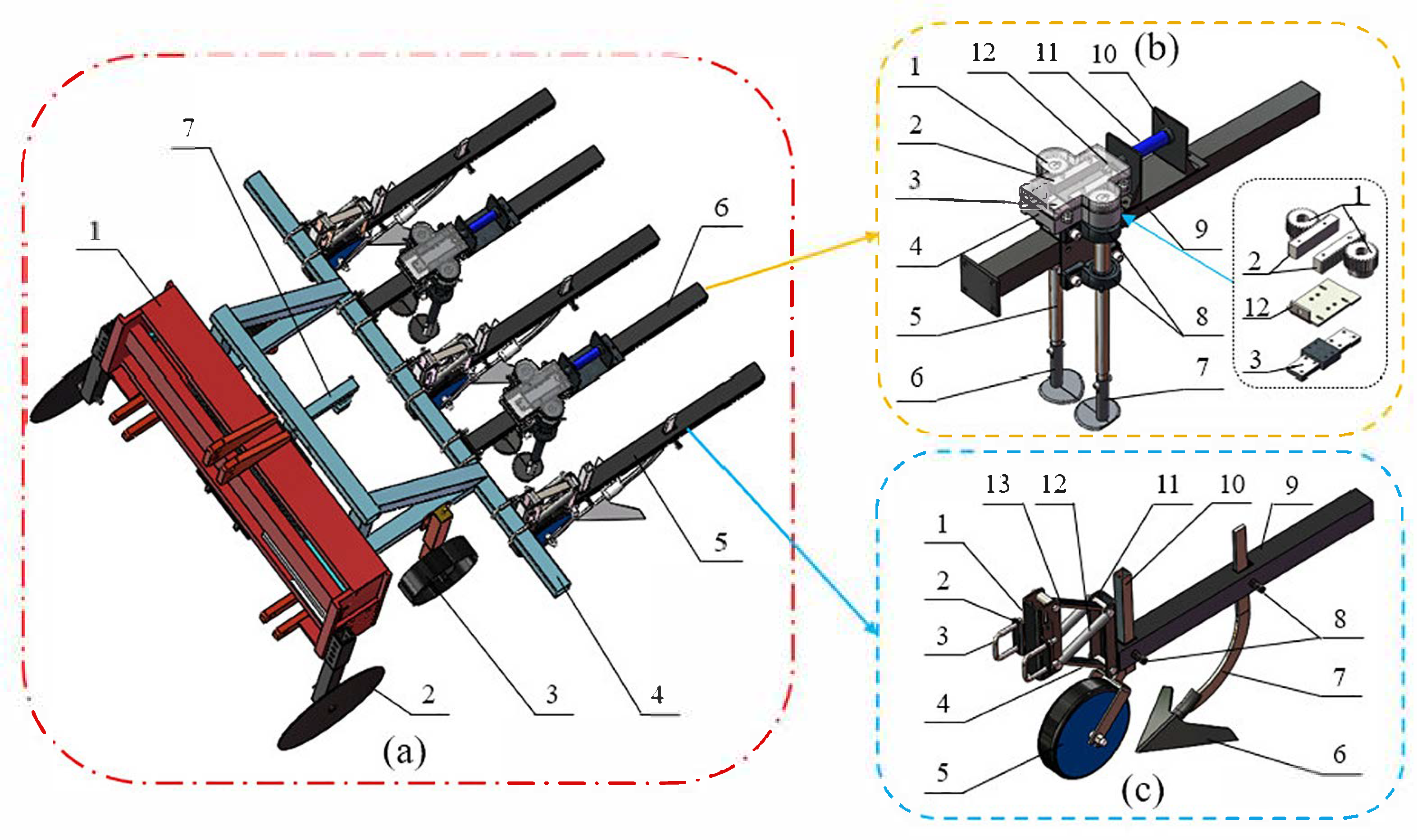
The weeding system primarily comprises an alignment device, directional wheels, depth limiting wheels, inter-row weeding single group, intra-row weeding single group, vision system, and other components. The overall structure is shown in Figure 1a. Among them, the intra-row weeding single group eliminates the intra-row weeds of the crop, which is composed of gear, rack, sliding block and guide rail, hoe blade shaft, right intra-row weeding knife, left intra-row weeding knife, double-acting hydraulic cylinder, as shown in Figure 1b. The inter-row weeding single group, designed to eliminate weeds between crop rows, mainly includes parallel four-bar mechanism, inter-row weeding actuator, contour wheel, and shovel handle, as shown in Figure 1c. The weeding system is pulled by the tractor, and the tractor’s hydraulic system provides power for the alignment device and the intra-row weeding single group.

2.1.2. Operating Principle of the Weeding System

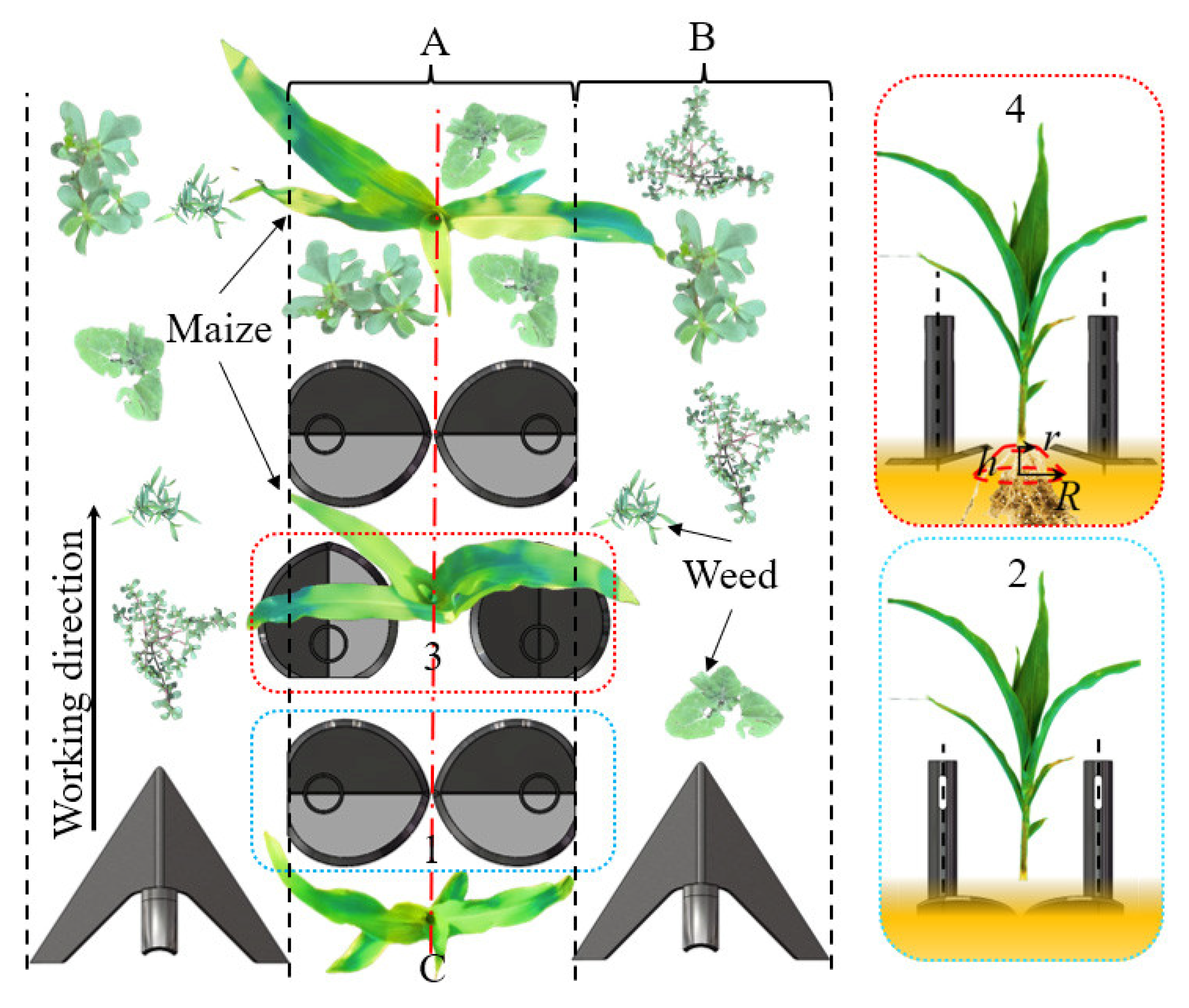
During the weeding operation, the vision system captures field images in real time. The maize seedling positions are identified via an image processing algorithm, which subsequently directs the alignment device to adjust the implement’s position in the field. When the intra-row weeding unit encounters seedlings, the hydraulic cylinder piston rod extends, driving the inter-row weeding knife to rotate outward and open via a rack-and-pinion mechanism to avoid the seedlings. After crossing the seedlings, the piston rod is retracted, and the intra-row weeding knife is driven by the rack and pinion device to rotate and close inward to complete the intra-row weeding operation. The inter-row weeding actuators remove weeds between crop rows as the implement moves forward. The operation process of the weeding system is shown in Figure 2.

2.2. Measurement of Maize Seedling Parameters and Establishment of Protected Zones

2.2.1. Measurement of Morphological Indicators

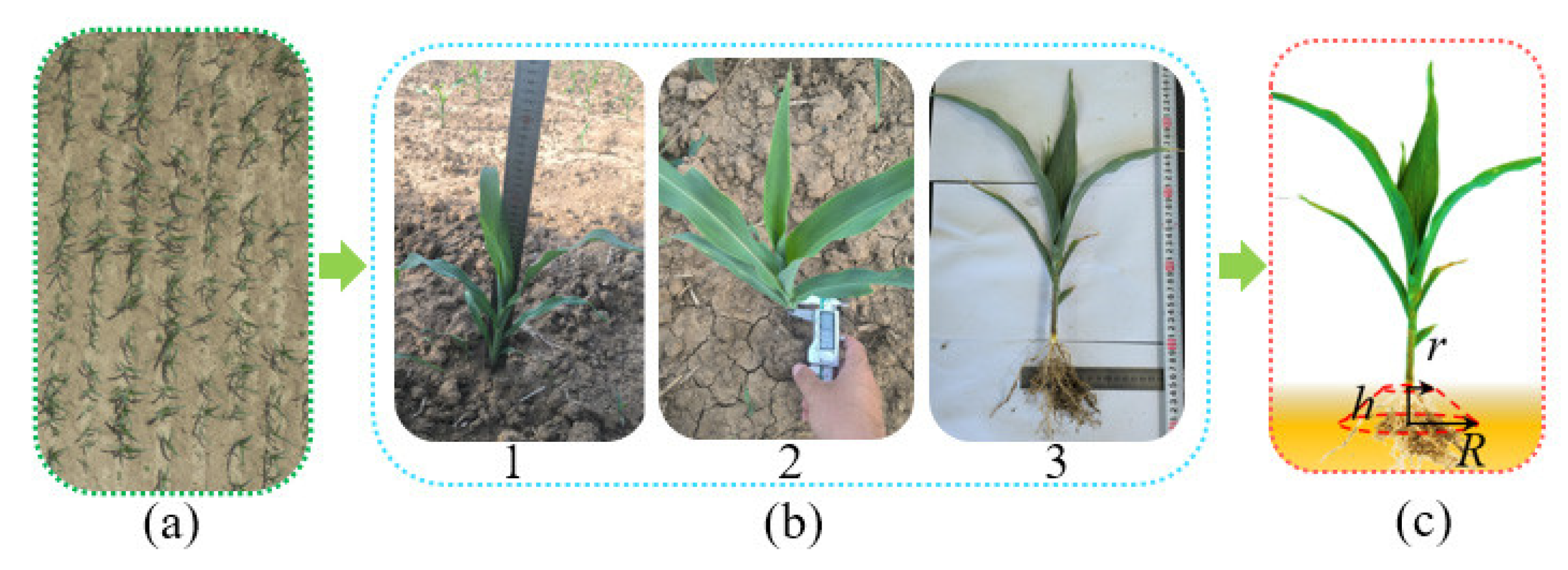
At the National Agricultural Science and Technology Park in Fuyang City, Anhui Province (115°24′ E, 32°59′ N), an experimental field was established with a planting density of 52,500 plants per hectare. The row spacing was 60 cm, the seed spacing was 32 cm, and the planting variety was Nongke Glutinous 336. In the experimental field, five statistical areas were delineated using the five-point sampling method. Within each statistical area, four maize seedlings were randomly selected, yielding a total of 20 seedlings. Morphological indicators including plant height, stem diameter, and root system radial diameter at 30 mm below ground level were measured. To accurately measure the root radius, the seedlings along with the surrounding soil were collected and brought to the laboratory. The soil around the roots was removed using a brush and small wooden strips while maintaining the root–soil distribution. The root radius at a depth of 30 mm below the soil surface was then measured using a ruler, as shown in Figure 3.

2.2.2. Measurement Results and Establishment of Protected Areas

The measurement results for morphological indicators such as plant height and stem diameter are shown in Table 1. Based on these measurements, the average plant height of maize seedlings is 31.5 cm, the average stem diameter (calculated from the average length of the long axis) is 13.10 mm, and the average root radiation diameter at 30 mm underground is 68.4 mm. The crop protection zone is established to minimise damage to crop root systems during weeding operations [39]. An excessively large protection zone reduces the coverage area around crops, thereby lowering weeding efficiency. Conversely, an overly small protection zone risks the weeding knives damaging seedlings and roots [27,40]. Based on relevant studies and the measured morphological indices, a frustum-shaped three-dimensional spatial protection zone was established. The zone is centred on the maize seedlings, with the upper base being the soil surface, the upper radius (r) being 15 mm, the depth (h) being 30 mm, and the lower radius (R) being 40 mm, as shown in Figure 3c. Avoiding this protective zone during intra-row weeding operations can effectively reduce damage to the crop roots.

2.3. Key Component Design

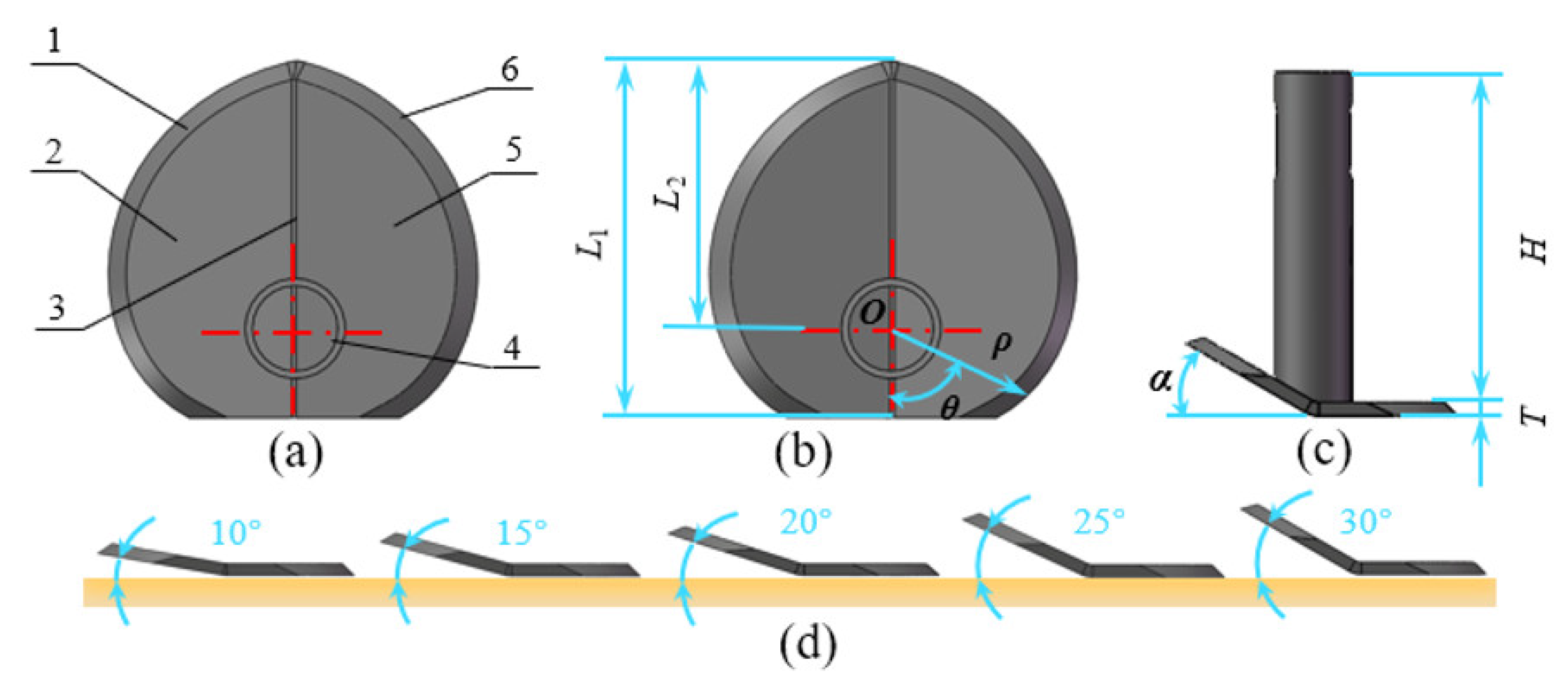
The structural and dimensional parameters of the intra-row weeding knife significantly affect weeding performance [27]. The weeding knife mainly consists of a main cutting edge, main blade section, bending line, handle, secondary blade section, and secondary cutting edge, as illustrated in Figure 4a. The main structural dimensions of the weeding knife include the total knife length L1, the rotational centre of the knife shaft located on the bending line, the distance from the rotational centre to the tip of the knife L2, the angle α between the side blade edge and the horizontal plane, the handle height H, and knife thickness T, as shown in Figure 4b,c.
The total length of the weeding knife directly influences the operational coverage area. Excessive length results in an enlarged coverage zone, which increases both the difficulty of control during seedling avoidance and operational energy consumption. Conversely, insufficient length reduces the coverage area, rendering the operation prone to missing weeds. The total length of the weeding knife is generally expressed as:
W 2 L 1 W
The rotational centre of the knife is located on the bending line. The position of the rotational centre affects the resistance to rotation during seedling avoidance weeding. Based on design experience, L2 is generally:
W 4 L 2 L 1
where W is the size of the intra-row weeding operation area, which typically extends 180 mm symmetrically on both sides of the seedling band centreline in domestic maize field weeding equipment [40]. Considering the design as a whole:
L 1   =   100   mm L 2   =   75   mm    
To prevent grass from tangling and reduce energy consumption during the weeding operation, the cutting edge curve design of the main cutting edge and secondary cutting edge of the intra-row weeding knife is based on the commonly used Archimedean spiral curve in rotary tiller knives. The equation for the curve is:
ρ   = ρ 0 + c θ
where ρ is the radial distance of the spiral, mm. ρ0 is the initial radial distance of the spiral, mm. c is the Archimedean spiral coefficient, representing the increase (or decrease) in the radial distance for every 1-degree increase in the angle, mm/°. θ denotes the polar angle of any point on the Archimedean spiral, °. The designed total length of the knife L1 is 100 mm. With the rotation centre of the knife as the origin O, the curve of the single-side weeding knife extends from 0° to 180°. The starting radial distance ρ0 is 25 mm, and the radial distance ρ1 after rotating counterclockwise by 180° is 75 mm. The coefficient c is:
c   =   ρ 1 ρ 0 180
During weeding operations, the weeding knife should ensure soil loosening without bringing subsoil to the surface layer [41]. To investigate the influence of the bending angle on weeding performance, five variations of intra-row weeding knives were designed. The bending angles were set at 10°, 15°, 20°, 25°, and 30°, respectively, as illustrated in Figure 4d.
The weeding knife is installed on the blade shaft through bolt connection. For easy maintenance and disassembly, the handle should not be too long and is designed to be 120 mm. During operation, the weeding knife is in prolonged contact with the soil. To prevent damage to the tool and improve its service life, a wear-resistant material, 65 Mn, is selected. To avoid deformation of the tool after contact with the soil, the knife thickness T is designed to be 5 mm.

3. Results and Discussion

3.1. DEM–MBD Coupled Simulation Modelling

3.1.1. Multi-Body Dynamics Modelling

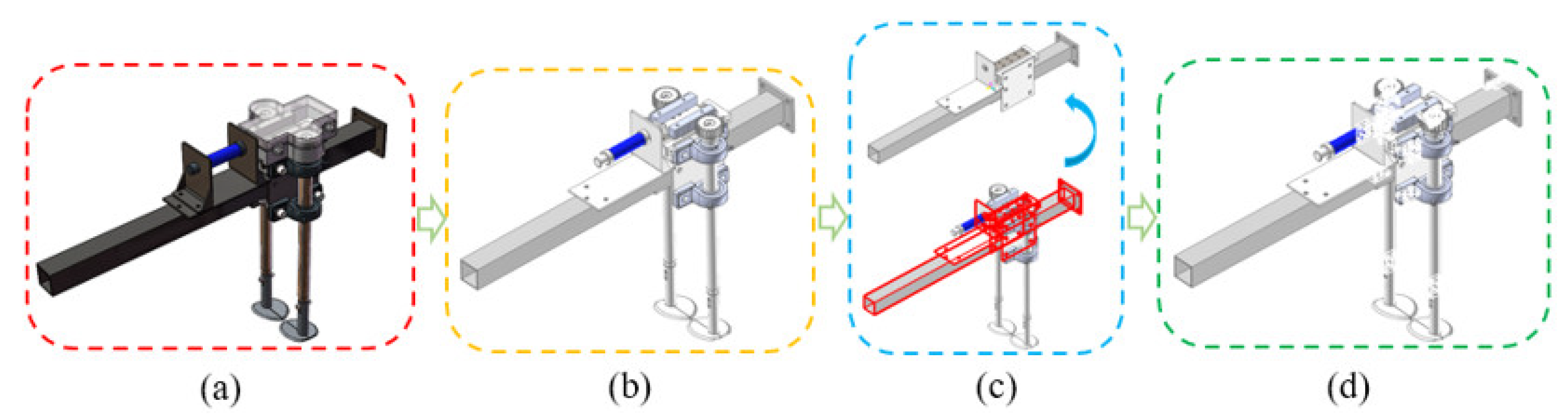
Based on the dimensional and structural parameters of each component within the intra-row weeding unit, three-dimensional solid modelling was performed using SolidWorks (2016) software at a 1:1 scale, as illustrated in Figure 5a. To enhance simulation efficiency, irrelevant components for weeding operations, such as dust covers, bolts and nuts, were omitted during the model process, as illustrated in Figure 5b. The core components of the weeding unit include double-acting hydraulic cylinders, gears, racks, sliders and guide rails, bearing with seat, hoe blade shaft, left intra-row weeding knife, right intra-row weeding knife and tray. These components were assembled within SolidWorks (2016), and the assembled model was saved in the .x_t format for import into RecurDyn (V9R2) software. When importing the intra-row weeding unit model into RecurDyn (V9R2), the assembly hierarchy was removed to facilitate subsequent constraint and contact definitions; all components were imported as individual parts to enable easier setup of interactions and constraints during simulation.
Constraints and contacts shall be defined prior to the simulation of the multi-body dynamic model. Components that do not involve interaction during the simulation, including the crossbeam, hanger frame and hydraulic cylinder support, are merged into a single entity by means of the Merge module, as illustrated in Figure 5c. This approach not only reduces the number of constraints and contacts to be defined but also enhances the simulation efficiency.
Based on the working principle of the intra-row weeding unit, contacts and constraints were applied to the key components of the model, as illustrated in Figure 5d. The motion of components in the model can be divided into two types: the forward motion of the weeding single group accompanying the implement and the telescopic motion of the double-acting hydraulic cylinder. During the extension and retraction of the hydraulic cylinder, the rack undergoes reciprocating motion, driving the gear to rotate and thereby turning the intra-row weeding knife. The main constraints and contacts of the model are shown in Table 2.

3.1.2. Discrete Element Method Modelling

Soil Intrinsic Parameters
The simulation parameters comprise the intrinsic parameters and contact parameters of soil [42]. The soil intrinsic parameters include moisture content, density, stacking angle, etc. Soil intrinsic parameters can be measured by instruments or obtained through relevant literature [42]. According to the “Standard for geotechnical testing method” (GB/T50123-2019) [43], the simulation-related parameters such as soil moisture content, density and stacking angle in the weeding test field were measured. The measurement results are shown in Table 3. The remaining parameter settings were referenced from relevant studies [44,45].
Soil particle size distribution analysis was conducted on samples from the experimental field. The results indicated that 81.5% of the soil particles ranged from 0.075 to 2 mm, while 12.55% were smaller than 0.075 mm and 5.95% exceeded 2 mm. The soil was classified as sandy loam. To balance computational efficiency with simulation accuracy, the simulated particle size was set to five times the actual mean diameter [46,47]. According to the soil particle size distribution of the experimental field, the particle diameter in this simulation was set to 5 mm.
Contact Parameters
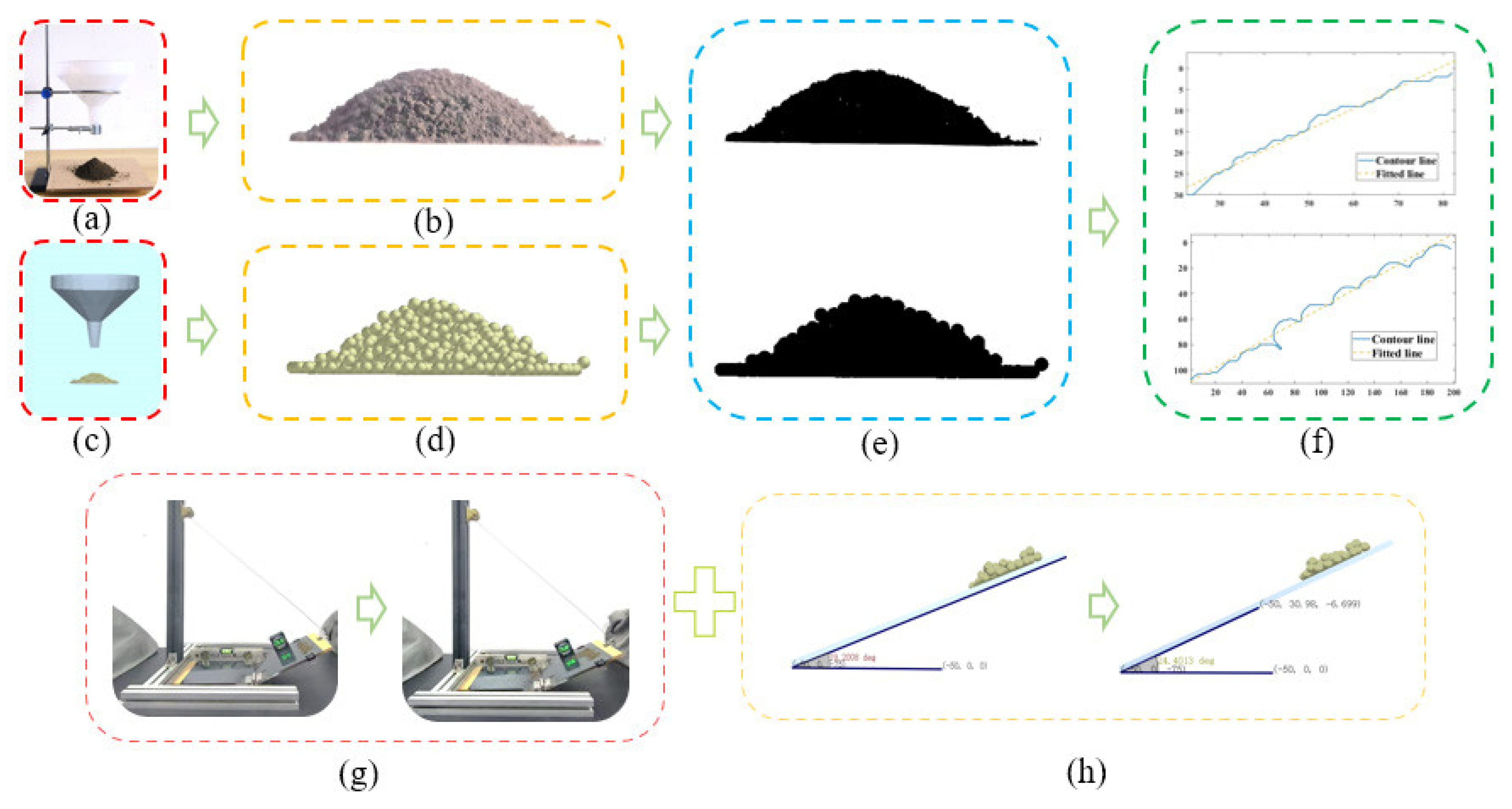
The inter-particle soil contact parameters were calibrated through physical tests of stacking angle and EDEM software simulation experiments. In the simulation, the Hertz–Mindlin with JKR model was adopted for soil–soil contact, whilst the Hertz–Mindlin (no slip) model was selected for the interaction between the soil and the weeding knife (65 Mn) [45].
The inter-particle soil contact parameters were calibrated through physical tests of stacking angle and EDEM software simulation experiments, and the calibration procedure is shown in Figure 6a–f. The contact parameters between soil and the soil-engaging components (65 Mn) were calibrated using rolling friction tests in combination with EDEM simulations, and the calibration procedure is shown in Figure 6g,h. The calibrated parameter values are listed in Table 4.
3.1.3. Configuration of Parameters for DEM–MBD Coupled Simulation
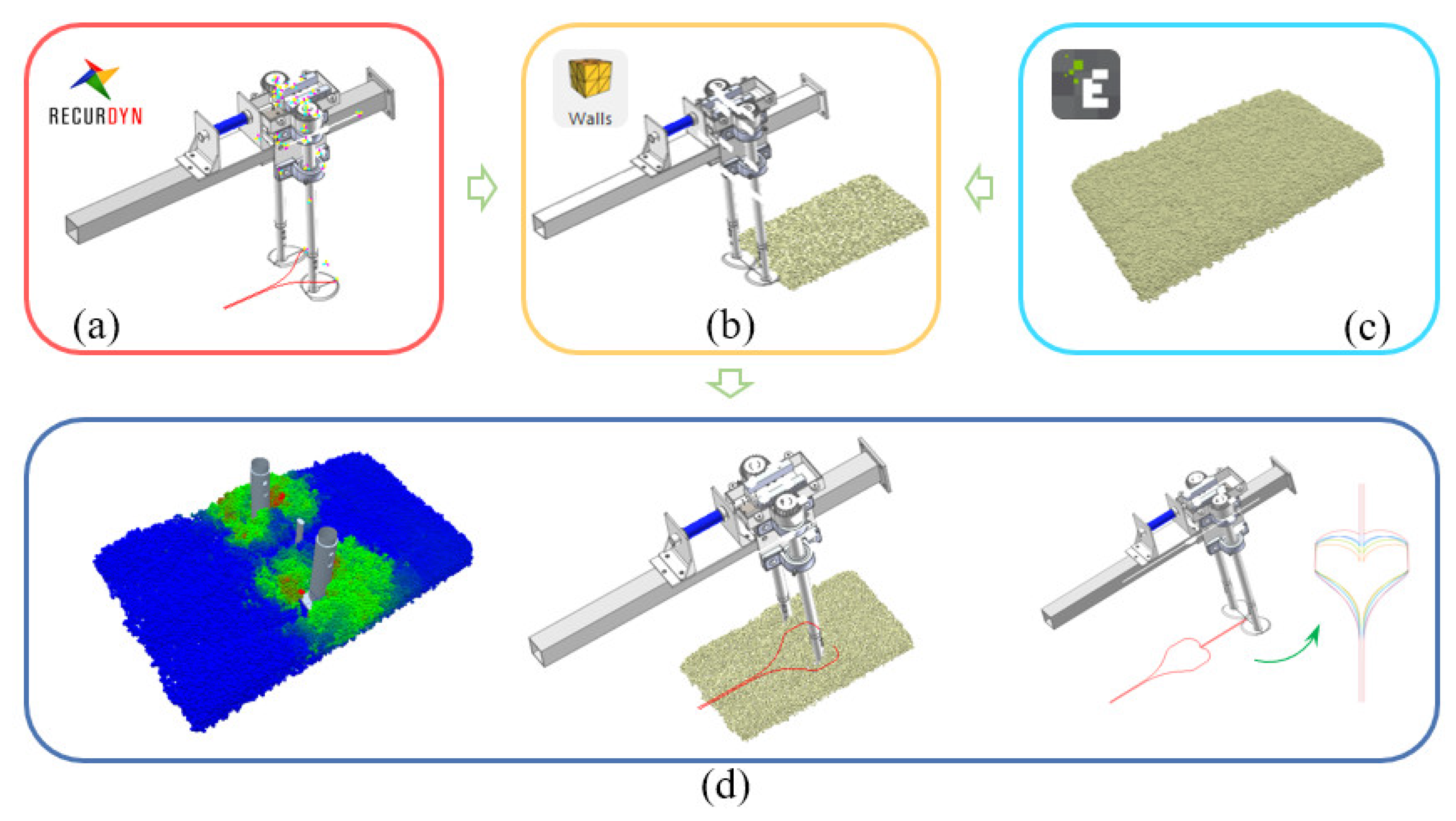
The simulations were conducted using EDEM 2020 coupled with RecurDyn V9R2. In RecurDyn, the simulation parameters of the single intra-row weeding unit were set according to the experimental design, and a ‘Wall’ file was generated, as shown in Figure 7a. In EDEM, soil particles were created based on parameters such as soil density, and the simulated field plot was established, as depicted in Figure 7c. To ensure the acquisition of sufficient simulation data, the plot dimensions were set to 500 × 300 × 50 mm. The ‘Wall’ file was then imported into EDEM, with the simulation time step set to 15.491% of the Rayleigh time step (5 × 10⁻⁵ s) and the data saving interval set to 0.01 s. To maintain temporal synchronisation between the multi-body dynamics and discrete element simulations, the EDEM simulation duration was adjusted to 2 s. The coupled weeding simulation was initiated and completed by activating the EDEM coupling interface module. The coupled simulation process is shown in Figure 7.

3.2. Simulation Metrics and Methodology

To optimize the operational performance of intra-row weeding single group, single-factor weeding simulations based on DEM–MBD coupling were conducted. The principal factors influencing weeding performance during operation were the bending angle of the weeding knife, the machine operating speed, and the hydraulic cylinder extension–retraction speed. The spatial coverage of the target area by the intra-row weeding knife and the intrusion rate into the protected zone were used as surrogate indices for the weeding rate and the crop injury rate, respectively.
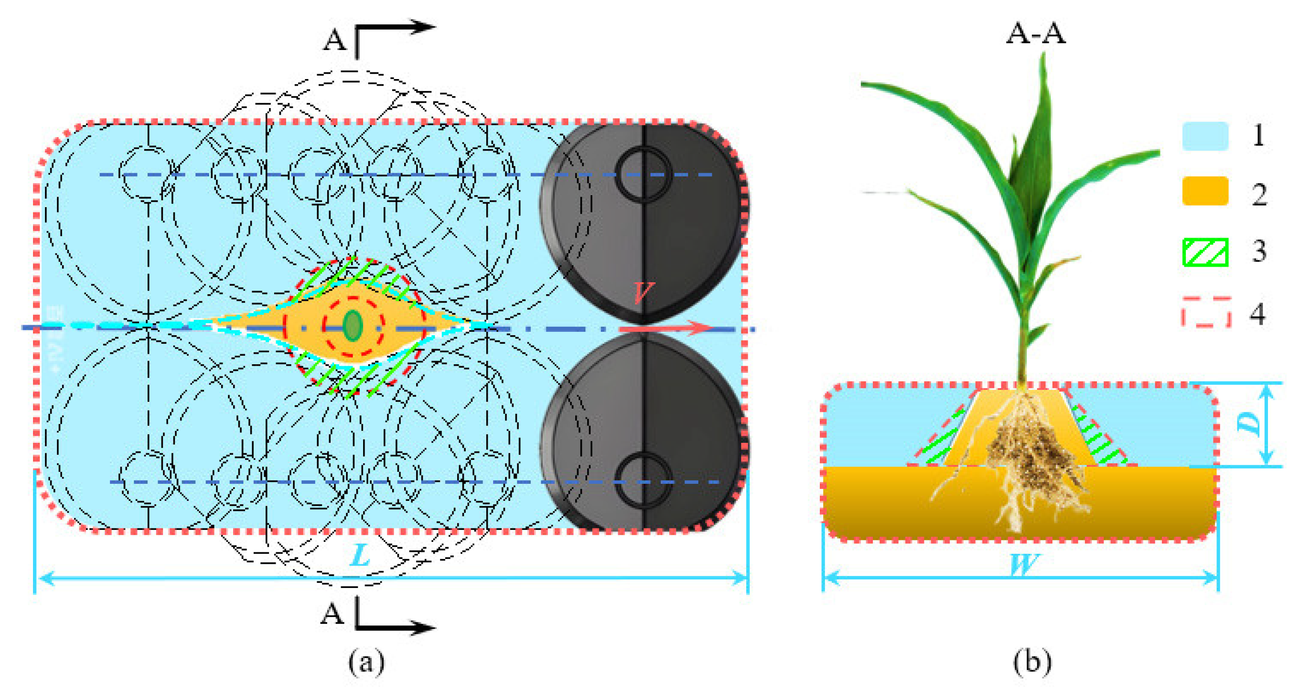
The data collection area for the simulation was defined as a symmetrical region centred on the seedling, as shown in Figure 8, where region 4 denotes the protection zone. The planting row spacing for fresh maize in the experimental field is 320 mm. The statistical region for the simulation test has a length (L) of 320 mm, a width (W) of 200 mm, and a depth (D) of 30 mm.
After coupling the simulation test, the volume of the weeding knife coverage area (Region 1 in Figure 8) and the volume of the weeding knife intrusion into the protection zone (Region 3 in Figure 8) are calculated. The inter-row weeding knife coverage rate and intrusion rate rare then calculated using the following formulas:
f   =   V f V z × 100 %
r = V r V b × 100 %
where   f represents the weeding knife coverage rate, %. V f is the volume of the weeding knife coverage area, mm3. V z is the total volume of the weeding knife operation area, mm3. r represents the intrusion rate, %. V r is the volume of the overlap between the weeding knife and the protection zone, mm3. V b is the volume of the protection zone, mm3.
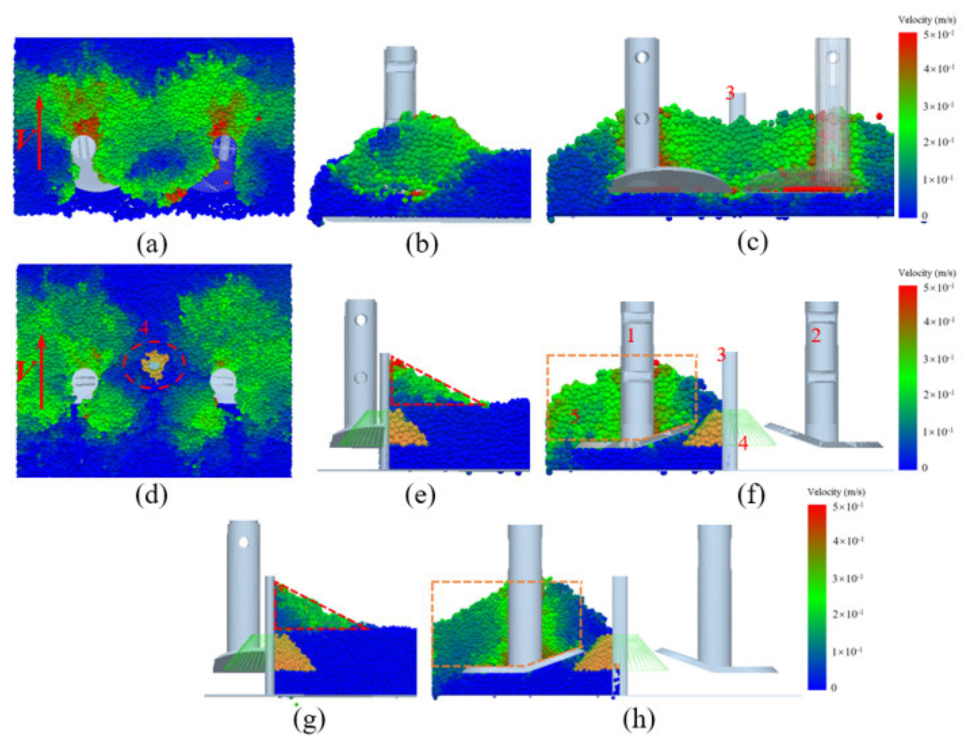
During weeding operations, the intra-row weeding unit initially remains in a closed state, with the knife tips facing each other. As the implement advances, the main cutting edge of the knife performs a sliding cut through the soil and weed root systems, as illustrated in Figure 9a–c. The velocity and distribution of soil particles shown in the figure indicate that the weeding knife effectively covers the working area. When encountering seedlings, the weeding knife rotates outward to avoid the crop roots while simultaneously removing the surrounding weeds, as shown in Figure 9d–f. At this time, both the main and secondary cutting edges simultaneously cut through the soil and weeds. The velocity and distribution of soil particles shown in the figure demonstrate that the left and right secondary cutting edges effectively avoid the crop root protection zone.
To accurately calculate coverage and intrusion rates, the number of particles in each area is used instead of the area volume. When the particle diameter is relatively large, fewer particles come into contact with the tool as it intrudes into the protection zone. As the particle diameter decreases, more particles fill the same volume, and the number of particles contacted by the tool during intrusion correspondingly increases. However, the tool’s effective spatial coverage remains broadly consistent, as indicated by the red and yellow dashed lines in Figure 9e–h. Numerical simulations were therefore performed under identical parameter settings using particles with diameters of 3 mm and 5 mm. The operating speed was set to 1.5 km/h, the hydraulic cylinder extension/retraction speed to 0.25 m/s and the tool angle to 20°. Coverage and intrusion ratios were calculated for each case. Each simulation was repeated three times, and the mean value was reported. For the 3 mm particles, the mean coverage and intrusion ratios were 90.45% and 4.06%, respectively. For the 5 mm particles, repeated measurements yielded mean ranges of 89.33–91.15% for coverage and 4.03–4.85% for intrusion. The differences between the two cases were within 1%. Nevertheless, the average runtime for soil generation and coupled simulations using 3 mm particles exceeded 19 h, whereas the corresponding runtime for 5 mm particles was only 5 h under the same conditions. Given the negligible loss in accuracy, a particle diameter of 5 mm provides substantially higher computational efficiency.
This study employs soil particles with a diameter of 5 mm, whose individual volume constitutes a fixed value. The simulated statistical region (320 × 200 × 30 mm) and protection zone volume substantially exceed the volume of a single particle. The volumes of the statistical region and protection zone may be approximated as the product of particle count and particle volume, exhibiting a linear relationship with particle quantity. Substituting particle count for the volumes of the statistical region and protection zone differs only by a constant proportionality factor. Replacing volume overlap with particle counting substantially reduces post-processing complexity without affecting the relative magnitudes or trends of coverage and intrusion rates. Using the post-processing module of EDEM software, the number of moving particles and the total number of particles within each region during the weeding operation are extracted.

3.3. Single-Factor Experiment

To investigate the impact of the operational speed, hydraulic cylinder extension/retraction speed and weeding knife bending angle on the performance of the weeding operation, single-factor experiments were conducted for each parameter. The ranges for each parameter were as follows: operational speed (0.9–2.1 km/h), hydraulic cylinder extension/retraction speed (0.15–0.35 m/s), and weeding knife bending angle (10–30°).

3.3.1. Operational Speed

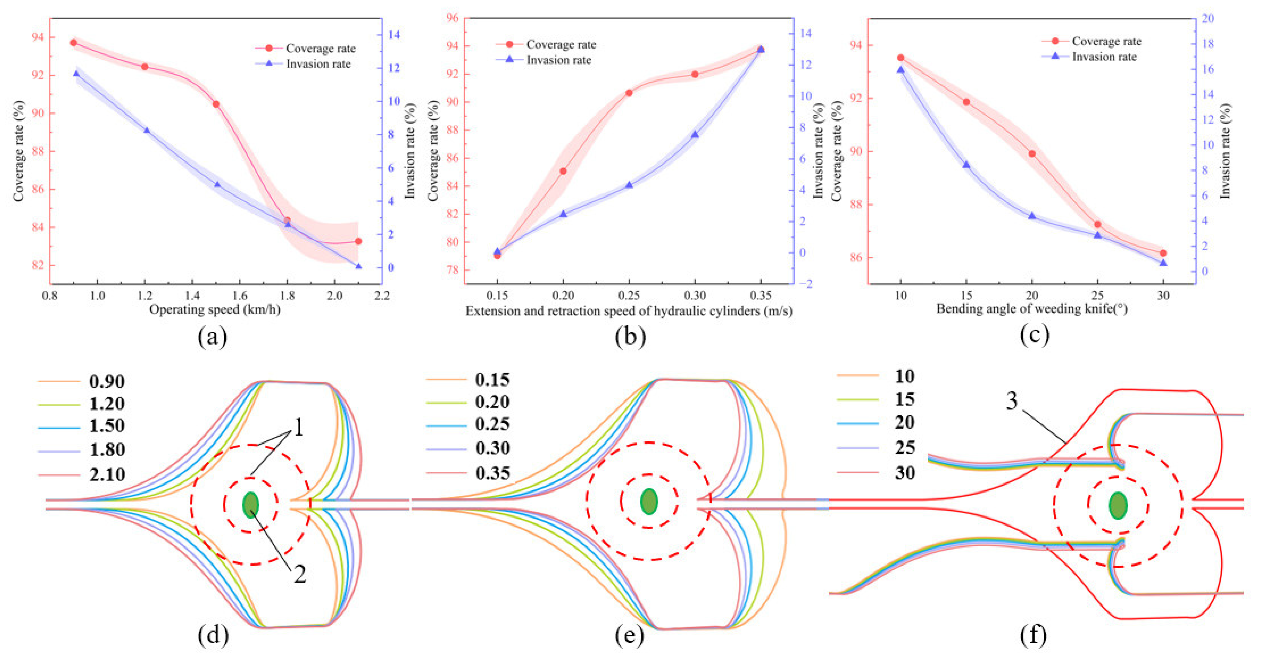
Simulation experiments were conducted across five levels of operational speed (0.9–2.1 km/h), whilst maintaining a constant hydraulic cylinder extension/retraction speed of 0.25 m/s and a weeding knife bending angle of 20°. When the hydraulic cylinder extension/retraction speed and the bending angle of the weeding knife were kept constant, increasing the operating speed led to a gradual decrease in both the coverage rate and the intrusion rate of the intra-row weeding knife, as shown in Figure 10a. The movement trajectories of the weeding knife tip at different parameters are shown in Figure 10d. As indicated by the red trajectory in Figure 10d, at higher operational speeds, the displacement of the knife along the direction of travel during the opening and closing phases increased. This led to a reduction in the volume of the covered weeding area, thereby diminishing the efficacy of intra-row weed removal. Conversely, at lower operational speeds, the longitudinal displacement during the opening and closing phases was reduced; consequently, the knife failed to exit the protection zone prior to closure, resulting in intrusion into the protected area. Based on these findings, an operational speed range of 1.2–1.8 km/h was selected for the subsequent orthogonal experiments.

3.3.2. Hydraulic Cylinder Extension/Retraction Speed

Simulation experiments were conducted across five levels of hydraulic cylinder extension/retraction speed (0.15–0.35 m/s), whilst maintaining an operational speed of 1.5 km/h and a weeding knife bending angle of 20°. When the operational speed and weeding knife bending angle remained unchanged, increasing the hydraulic cylinder extension speed resulted in an increase in the coverage rate of the intra-row weeding knife, but also a gradual increase in the intrusion rate into the protected area, as shown in Figure 10b. The movement trajectories of the weeding knife tip at different parameters are shown in Figure 10e. Higher hydraulic cylinder speeds corresponded to rapid opening and closing of the weeding knife, yielding higher coverage rates. However, the knife failed to exit the protection zone prior to closure, leading to an increased intrusion rate and a higher risk of damage to the crop root system. Conversely, lower hydraulic cylinder speeds resulted in slower opening and closing actions and a longer travel path during seedling avoidance. This reduced spatial coverage around the crop, thereby impeding effective weed removal in the crop vicinity. Consequently, a hydraulic cylinder extension/retraction speed range of 0.20–0.30 m/s was selected for the orthogonal experiments.

3.3.3. Weeding Knife Bending Angle

Simulation experiments were performed for five levels of weeding knife bending angle (10–30°) under conditions of an operational speed of 1.5 km/h and a hydraulic cylinder speed of 0.25 m/s. When the operational speed and hydraulic cylinder extension speed remained unchanged, it was observed that as the weeding knife bending angle increased, the coverage rate of the intra-row weeding knife gradually decreased, and the intrusion rate into the protected area also decreased, as shown in Figure 10c. Since the knife tip trajectories for different bending angles were similar, the impact of the bending angle on weeding performance was further explored by extracting the trajectory of the midpoint of the secondary knife edge at different angles, as shown in Figure 10f. From the figure, it is evident that when the bending angle is too large, the trajectory moves further away from the protected area, indicating that the side knife works further from the protected area, reducing both coverage and intrusion rates. Conversely, if the bending angle is too small, the secondary blade edge works too close to the protected area, increasing the likelihood of intrusion and causing potential root system damage. Therefore, the selected bending angle for the orthogonal experiment was determined to be 15–25°.

3.4. Orthogonal Experiment

Based on the Box–Behnken design principle, a three-factor, three-level quadratic orthogonal rotatable composite experiment was constructed. The operating speed (A), hydraulic cylinder extension/retraction speed (B), and weeding knife bending angle (C) were selected as the experimental factors, while the coverage rate (y1) and intrusion rate (y2) were used as the response variables. The coded levels of the experimental factors are given in Table 5.

3.5. Experimental Results and Analysis

3.5.1. Experimental Design and Results

The design and simulation results of the quadratic regression orthogonal rotational combination experiment are presented in Table 6.

3.5.2. Analysis of Experimental Results

Analysis of variance (ANOVA) and significance testing were performed on the data in Table 6 using Design-Expert 11.0 software; the results are summarized in Table 7. The ANOVA results indicated that the regression models for both coverage rate (y1) and intrusion rate (y2) were highly significant (p < 0.0001). The lack-of-fit terms were insignificant (p > 0.05), with values of 0.1191 and 0.4276, respectively. This demonstrates a high goodness of fit and confirms that the models accurately describe the relationships between the response variables and the experimental factors.
Analysis of the F-values revealed that the influence of the experimental factors on the coverage rate, in descending order of magnitude, was: hydraulic cylinder extension/retraction speed, operational speed, and weeding knife bending angle. Similarly, the order of influence on the intrusion rate was: hydraulic cylinder extension/retraction speed, operational speed, and weeding knife bending angle. This is because the proposed intra-row weeding knife adopts an active seedling-avoidance mechanism and is directly driven by a hydraulic cylinder, which governs the opening and closing rate of the knife. The opening–closing speed is critical for completing the avoidance manoeuvre. Any change in cylinder speed leads to a pronounced phase shift in knife deployment and retraction, thereby markedly altering coverage of, and intrusion into, the crop row zone. By contrast, the operating speed primarily controls the machine’s forward travel rate and thus the knife dwell time near the plant; it does not directly change the knife’s coverage and intrusion states.
To characterize the relationships between A, B and C and the responses y1 and y2, quadratic polynomial regression models were established. Following the elimination of insignificant terms, the regression equations were obtained as follows:
y 1   =   90.57     3.56 A     +   4.64 B     1.51 C       1.57 A C       2.37 A 2     5.09 C 2 y 2   =   4.40     1.05 A   +   2.42 B     0.75 C   +   0.68 A B     0.75 A C     1.8 C 2    
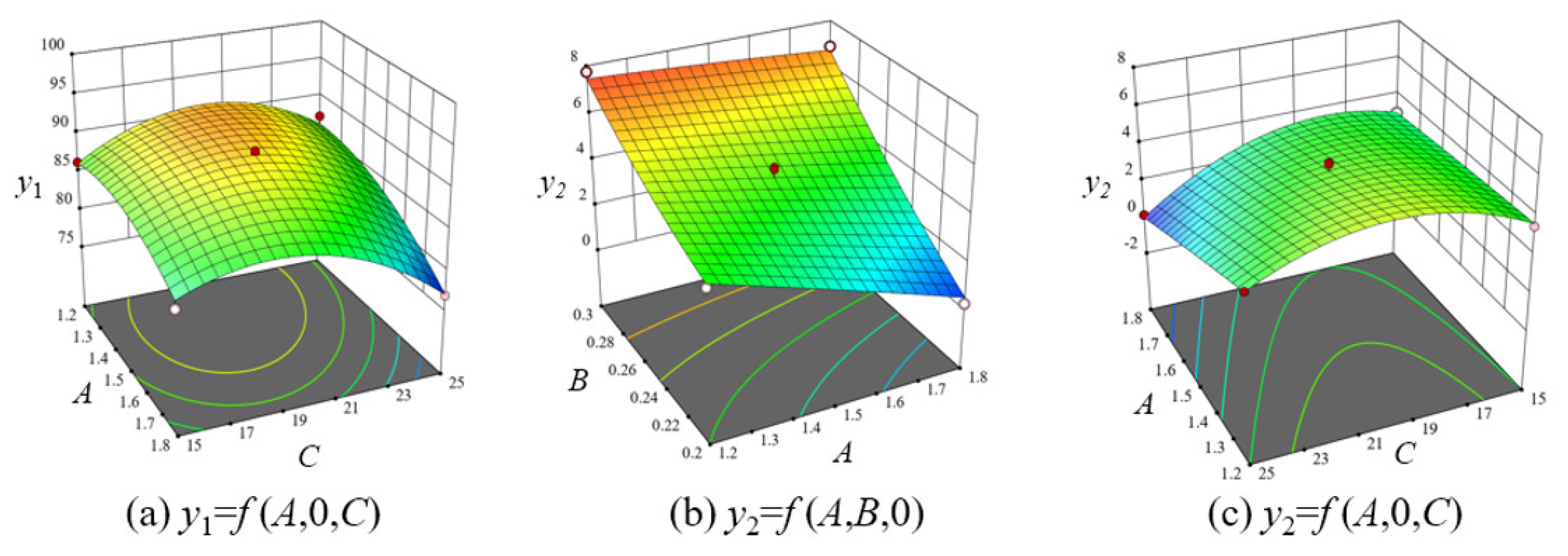
As shown in Figure 11a, when B (extension and retraction speed of the hydraulic cylinders) is set to 0.25 m/s, y1 (coverage rate) varies markedly with A (operating speed) and C (bending angle of the weeding knife). With A held constant, y1 initially increased and subsequently decreased as C increased. As the bending angle increased, the cutting action on surface soil particles intensified, thereby increasing the coverage rate. However, at excessively large bending angles, the cutting action on bottom-layer particles diminished, resulting in a reduced coverage rate. With C held constant, y1 demonstrated an overall downward trend as A increased. The reason may be that with the increase in working speed, the working stroke becomes larger when the weeding knife avoids seedlings, and the coverage rate of weeding in the surrounding area of crops decreases.
As shown in Figure 11b, when C (bending angle of the weeding knife) is set to 20°, y2 (intrusion rate) exhibits significant variation with respect to parameters A (operating speed) and B (hydraulic cylinder extension/retraction speed). With A held constant, y2 generally exhibited an upward trend as B increased. As the extension speed increases, the opening and closing speed of the weeding knife accelerates, resulting in a shorter travel distance during seedling avoidance. This makes the weeding knife more prone to intruding into the protected zone, leading to an elevated intrusion rate. When the B value remains constant, y2 exhibits an overall downward trend as A increases. As the operating speed increases, the stroke of the weeding knife when avoiding seedlings increases, and the space for the weeding knife to avoid the protected area increases, resulting in a decrease in the intrusion rate.
As shown in Figure 11c, when B (hydraulic cylinder extension/retraction speed) was set to 0.25 m/s, the y2 (intrusion rate) showed significant variation with the A (operating speed) and C (bending angle of the weeding knife). With A held constant, y2 initially increased and then decreased as C increased. When the bending angle is small, the weeding knife covers a larger area during crop avoidance and the auxiliary knife is closer to the protected zone, making intrusion more likely. As the bending angle increases, the intrusion point of the auxiliary knife shifts from the bottom towards the middle of the protected zone and then gradually moves away, leading to an initial increase followed by a decrease in disturbance. With C held constant, y2 exhibited an overall downward trend as A increased. Consistent with previous findings, higher operational speeds extended the operational path during seedling avoidance, allowing sufficient space to navigate around the protection zone, thereby mitigating intrusion.

3.5.3. Parameter Optimisation

To further enhance the weeding performance of the mechanical weeding system and determine the optimal combination of experimental factors, multi-objective optimization of the experimental parameters was conducted using Design-Expert software. The objectives were to maximize the coverage rate and to minimize the intrusion rate, with the objective functions and constraints defined as follows:
m a x y 1 ( A , B , C ) m i n y 2 ( A , B , C ) s . t . 1.2   km / h A 1.8   km / h 0.2   m / s B 0.3   m / s 15 ° C 25 °
The optimal parameter combination identified through numerical optimization comprised an operational speed of 1.487 km/h, a hydraulic cylinder extension/retraction speed of 0.222 m/s, and a weeding knife bending angle of 20.192°. Under these conditions, the predicted coverage rate was 87.98%, with an intrusion rate of 3.19%. Accounting for practical operational conditions and knife manufacturing constraints, the parameters for the field verification trials were refined to an operational speed of 1.5 km/h, a hydraulic cylinder speed of 0.22 m/s, and a bending angle of 20°.

3.6. Field Experiments

Field experiments encompass maize seedling detection tests and field weeding experiment. The experiment was carried out in the National Agricultural Science and Technology Park in Fuyang City, Anhui Province, China (115°24′ E, 32°59′ N). The experimental field featured a maize row spacing of 60 cm and a seed spacing of 32 cm, with a planting density of 52,500 plants per hectare. The maize variety used was Nongke Glutinous 336. The experiment was conducted when the maize seedlings reached the 3–5 leaf stage.

3.6.1. Maize Seedling Detection Trial and Results

Farmland images were acquired using an industrial camera module (RER-USBFHD01M-LS36, Shenzhen, China), with a maximum resolution of 1080 p and a maximum frame rate of 60 fps. During testing, the camera was mounted vertically above the ground at an installation height of h = 0.8 m. Prior to data acquisition, camera parameters were calibrated using the Camera Calibrator module in MATLAB 2021. After calibration, the intrinsic parameters were fx = 1501 pixels and fγ = 1499 pixels. The ground sampling distance (GSD) in both the horizontal and vertical directions was 0.53 mm/pixel. Under these settings, the ground field of view was 1.06 m × 0.54 m, fully covering two adjacent maize rows. A 10 m seedling strip was selected within the experimental area to count the number of maize seedlings. Seedling detection tests were conducted under good illumination (sunny) and low illumination (dusk) conditions. The YOLOv8-word model was used for detection, and the testing speed was 1.5 km/h.
As shown in Table 8, under favourable lighting conditions, maize detection accuracy ranged from 95.16% to 96.49%, with an average detection accuracy of 95.82%. In dimmer lighting, detection accuracy ranged from 92.98% to 93.55%, with an average detection accuracy of 93.32%, meeting field trial requirements. The detection performance is favourable due to the larger size and more pronounced characteristics of maize seedlings. To enhance the model’s detection accuracy in complex agricultural environments, a combination-based data augmentation method utilising traditional image processing operators was employed during training. This involved randomly combining techniques such as horizontal flipping, brightness adjustment, contrast transformation, saturation perturbation, Gamma correction, and Gaussian noise to augment the original images (1000 images) and their corresponding YOLO format labels (4000 images).

3.6.2. Field Weeding Experiments and Result

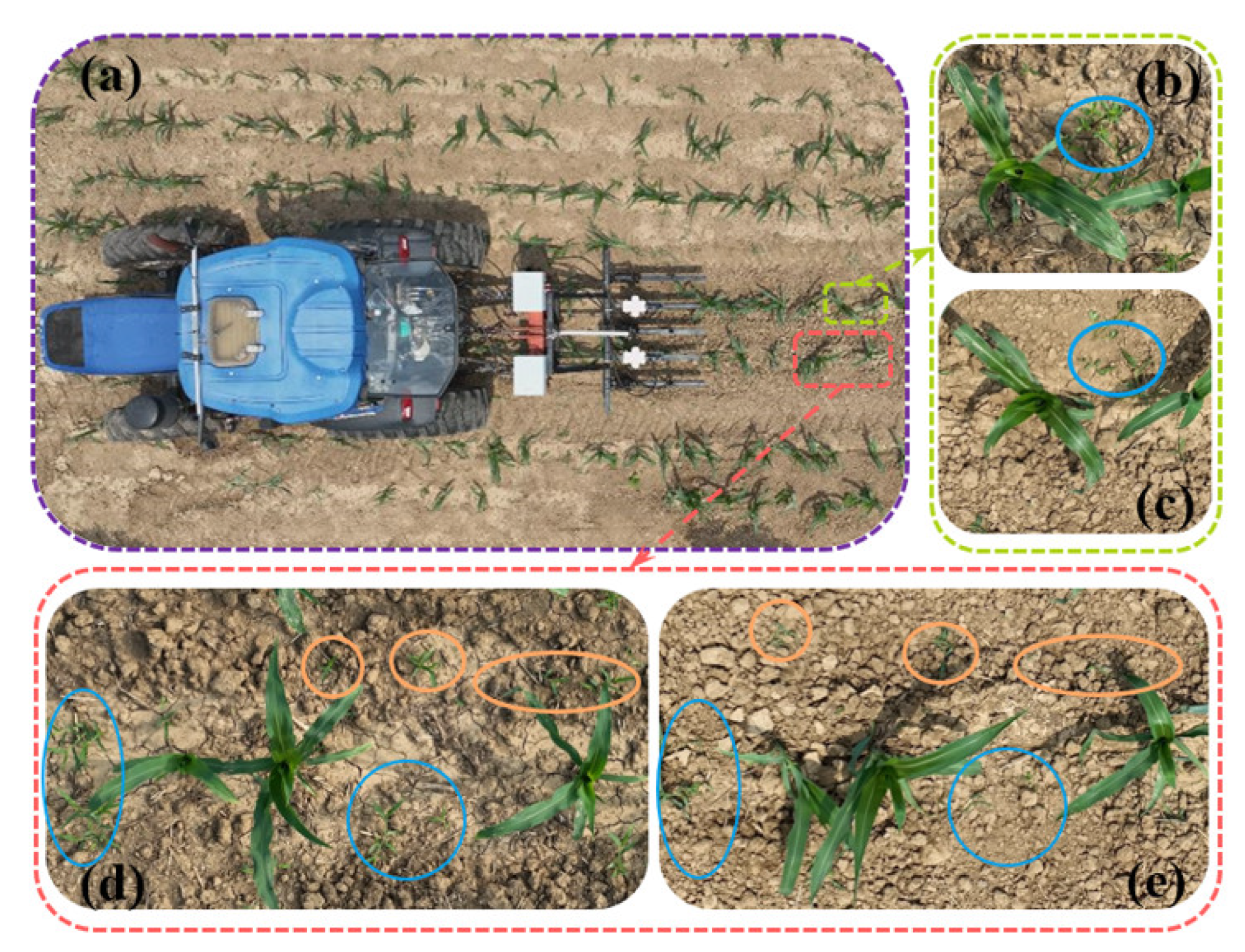
The experimental plot was 40 m in length and 20 m in width. Along the travel direction, the first 5 m was designated as the machine start-up zone, and the remaining area beyond 5 m was used as the measurement zone. With a hydraulic cylinder extension/retraction speed of 0.22 m/s and a weeding knife bending angle of 20°, field weeding trials were conducted at operating speeds of 1.2 km/h, 1.5 km/h (optimal setting), and 1.8 km/h, with each treatment repeated three times. The field experiment is shown in Figure 12.
The test indicators were the weeding rate and seedling injury rate. The calculation methods for these indicators are as follows:
R W = ( 1 N L N W ) × 100 %
R D = N D N C × 100 %
where RW is the weeding rate, %. NL is the number of weeds cut after weeding. NW is the total number of weeds before weeding. RD is the seedling injury rate, %. ND is the number of seedlings damaged after weeding. NC is the total number of crops before weeding.
The field trial results are summarised in Table 9. At an operating speed of 1.2 km/h, the highest mean weeding rate was 91.02%, while the mean seedling damage rate was also the highest at 3.83%. At 1.8 km/h, the weeding rate decreased to the lowest value of 87.84%, whereas the mean seedling damage rate was the lowest at 1.65%. With all other parameters held constant, both the weeding rate and the seedling damage rate decreased as the operating speed increased, which is consistent with the trends observed in the single-factor simulation tests. Under the optimal parameter combination, the weeding rate ranged from 89.79% to 91.54%, with a mean of 90.79%, and the seedling damage rate ranged from 1.72% to 3.33%, with a mean of 2.27%. Considering both weeding efficiency and seedling protection, an operating speed of 1.5 km/h was more suitable for field weeding. Overall, the proposed weeding system exhibited stable and reliable performance, enabling comprehensive, low-damage removal of weeds surrounding fresh maize plants. The results satisfy the agronomic requirements for weeding in fresh maize fields and provide a useful reference for the design and development of intelligent mechanical weeding equipment.

3.7. Research Limitations

Although a five-point sampling method was employed to ensure randomness, all test samples were collected from the same farm, the same growing season, and a single maize variety. While the operational performance of the weeding device has been validated under these conditions, the applicability of its findings across different production regions, soil types, and maize varieties requires further verification. Maize crops exhibit varying physiological indicators at different growth stages, necessitating validation of suitability across distinct growth cycles. When calculating coverage and infestation rates, the entire working surface of the knife was used as the statistical area, without accounting for the density gradient of particles near the knife edge. This constitutes a limitation of the present study. Future research will investigate the influence of minute areas such as the knife edge on parameters like coverage. Concurrently, systematic trials across regions, varieties, and environmental conditions will be conducted. The aim is to maintain stable weeding performance while enhancing the device’s adaptability to different regions and its practical application value.

4. Conclusions

This study addresses the challenge of weed control in fresh-eating maize fields by designing a comprehensive low-damage weeding system. To minimize damage to crop roots, a specialized intra-row weeding knife was designed based on the spatial distribution of maize roots and the agronomic requirements of weeding operations, following the principle of crop root protection.
To optimise the operational performance of the weeding system, EDEM–RecurDyn coupled simulations were employed. Single-factor experiments were conducted to investigate the effects of operating speed, hydraulic cylinder extension and retraction speed, and knife bending angle on coverage and intrusion rates, thereby determining the ranges for these parameters. Based on the Box–Behnken design principle, a three-factor, three-level quadratic regression orthogonal rotation combination experiment was conducted. The optimal parameter combination was determined to be an operating speed of 1.487 km/h, a hydraulic cylinder extension/retraction speed of 0.222 m/s, and a knife bending angle of 20.192°. Under these conditions, the predicted coverage rate and intrusion rate were 87.98% and 3.19%, respectively.
Field trials were conducted to evaluate the prototype, including maize seedling detection tests and field weeding experiments. The maize seedling detection results indicated that the detection accuracy was 95.82% under good illumination and 93.32% under low illumination, which satisfies the requirements for field experimentation. According to the optimal parameter combination obtained from the coupled simulation, the operating parameters of the implement for the field trials were determined. Field weeding experiments were conducted at operating speeds of 1.2 km/h, 1.5 km/h (optimal parameters), and 1.8 km/h, respectively, with a hydraulic cylinder extension and retraction speed of 0.22 m/s and a weeding knife bending angle of 20°. Each treatment was replicated three times. Considering both weeding efficiency and seedling damage rate, an operating speed of 1.5 km/h is more suitable for weeding operations. The experimental results showed that the weeding rate of the system ranged from 89.78% to 91.55%, with an average of 90.79%, while the seedling injury rate ranged from 1.72% to 3.33%, with an average of 2.27%. These results satisfy the requirements for low-damage weeding in fresh maize production and can provide a reference for the design and development of intelligent mechanical weeding equipment.

Author Contributions

Conceptualization, D.S., L.Q. and H.C.; methodology, L.Q. and H.C.; software, D.S.; validation, D.S., L.Q. and H.C.; data curation, D.S.; writing—original draft preparation, D.S.; writing—review and editing, L.Q. and H.C.; project administration, L.Q. and H.C.; funding acquisition, L.Q. and H.C. All authors have read and agreed to the published version of the manuscript.

Funding

This research was funded by the National Natural Science Foundation of China, grand number 32271998 and 32471989.

Institutional Review Board Statement

Not applicable.

Data Availability Statement

The data presented in this study are available on request from the correspondence author.

Conflicts of Interest

The authors declare no conflicts of interest.

References

  1. Von Redwitz, C.; Andert, S.; Bensch, J.; Forster, R.; Schatke, M.; Strehlow, B.; Ulber, L. Enhancing Arable Weed Diversity by Reduced Herbicide Use? J. Crop Health 2025, 77, 65. [Google Scholar] [CrossRef]
  2. Kumar, S.; Kumari, S.; Rana, S.S.; Rana, R.S.; Anwar, T.; Qureshi, H.; Saleh, M.A.; Alamer, K.H.; Attia, H.; Ercisli, S. Weed management challenges in modern agriculture: The role of environmental factors and fertilization strategies. Crop Prot. 2024, 185, 106903. [Google Scholar] [CrossRef]
  3. Gao, W.T.; Su, W.H. Weed Management Methods for Herbaceous Field Crops: A Review. Agronomy 2024, 14, 486. [Google Scholar] [CrossRef]
  4. Gatkal, N.R.; Nalawade, S.M.; Shelke, M.S.; Sahni, R.K.; Walunj, A.A.; Kadam, P.B.; Ali, M. Review of cutting-edge weed management strategy in agricultural systems. Int. J. Agric. Biol. Eng. 2025, 18, 25–42. [Google Scholar] [CrossRef]
  5. Wu, K.; Zhou, S.; Zeng, G.; Yang, H.; Wu, B. Technology to utilise and suppress weeds for sustainable maize production. Resour. Environ. Sustain. 2025, 22, 100279. [Google Scholar] [CrossRef]
  6. Fang, H.; Niu, M.; Wang, X.; Zhang, Q. Effects of reduced chemical application by mechanical-chemical synergistic weeding on maize growth and yield in East China. Front. Plant Sci. 2022, 13, 1024249. [Google Scholar] [CrossRef]
  7. Parven, A.; Meftaul, I.M.; Venkateswarlu, K.; Megharaj, M. Herbicides in modern sustainable agriculture: Environmental fate, ecological implications, and human health concerns. Int. J. Environ. Sci. Technol. 2025, 22, 1181–1202. [Google Scholar] [CrossRef]
  8. Kaur, S.; Dhanda, S.; Yadav, A.; Sagwal, P.; Yadav, D.B.; Chauhan, B.S. Current status of herbicide-resistant weeds and their management in the rice-wheat cropping system of South Asia. Adv. Agron. 2022, 172, 307–354. [Google Scholar] [CrossRef]
  9. Niu, L.-T.; Su, W.-H.; Zhang, H.-Y.; Wang, Q.; Dong, B.-W.; Peng, Y. Development of intelligent equipment for weed identification and variable spraying in lettuce fields based on instance segmentation framework. Eng. Appl. Artif. Intell. 2025, 159, 111634. [Google Scholar] [CrossRef]
  10. Zhou, W.; Li, M.; Achal, V. A comprehensive review on environmental and human health impacts of chemical pesticide usage. Emerg. Contam. 2025, 11, 100410. [Google Scholar] [CrossRef]
  11. Leskovac, A.; Petrović, S. Pesticide Use and Degradation Strategies: Food Safety, Challenges and Perspectives. Foods 2023, 12, 2709. [Google Scholar] [CrossRef]
  12. Jia, W.; Tai, K.; Wang, X.; Dong, X.; Ou, M. Design and simulation of intra-row obstacle avoidance shovel-type weeding machine in orchard. Agriculture 2024, 14, 1124. [Google Scholar] [CrossRef]
  13. Liu, C.; Yang, K.; Chen, Y.; Gong, H.; Feng, X.; Tang, Z.; Fu, D.; Qi, L. Benefits of mechanical weeding for weed control, rice growth characteristics and yield in paddy fields. Field Crops Res. 2023, 293, 108852. [Google Scholar] [CrossRef]
  14. Moshayedi, A.J.; Khan, A.; Geng, K.; Hu, J.; Kolahdooz, A. Advancing agricultural practices: Analyzing the role of robotics in corn farming. Int. J. Eng. Trans. A Basics 2025, 38, 1517–1532. [Google Scholar] [CrossRef]
  15. Moshayedi, A.J.; Wang, Z.; Sharifdoust, M.; Khoojine, A.S.; Zhang, W.; Kolahdooz, A.; Hu, J. Smart farming solutions: A user-friendly GUI for maize tassel estimation using YOLO with dynamic and fixed labelling, featuring video support. IEEE Access 2025, 13, 2169–3536. [Google Scholar] [CrossRef]
  16. Pai, D.G.; Kamath, R.; Balachandra, M. Deep Learning Techniques for Weed Detection in Agricultural Environments: A Comprehensive Review. IEEE Access 2024, 12, 113193–113214. [Google Scholar] [CrossRef]
  17. Rakhmatulin, I.; Kamilaris, A.; Andreasen, C. Deep neural networks to detect weeds from crops in agricultural environments in real-time: A review. Remote Sens. 2021, 13, 4486. [Google Scholar] [CrossRef]
  18. Li, J.-L.; Su, W.-H.; Hu, R.; Niu, L.-T.; Wang, Q. Smart weeding system with multi-sensor fusion for tomato plant detection and targeted micro-spraying of intra-row weeds. Comput. Electron. Agric. 2025, 237, 110598. [Google Scholar] [CrossRef]
  19. Zhao, C.-T.; Wang, R.-F.; Tu, Y.-H.; Pang, X.-X.; Su, W.-H. Automatic lettuce weed detection and classification based on optimized convolutional neural networks for robotic weed control. Agronomy 2024, 14, 2838. [Google Scholar] [CrossRef]
  20. Zheng, S.; Zhao, X.; Fu, H.; Tan, H.; Zhai, C.; Chen, L. Design and Experimental Evaluation of a Smart Intra-Row Weed Control System for Open-Field Cabbage. Agronomy 2025, 15, 112. [Google Scholar] [CrossRef]
  21. Li, Y.; Qu, Y.; Fang, Y.; Yang, J.; Lu, Y. Design and experiment of autonomous shield-cutting end-effector for dual-zone maize field weeding. Agriculture 2025, 15, 1549. [Google Scholar] [CrossRef]
  22. Tang, Z.; Xi, X.; Zhang, B.; Shi, Y.; Wang, Y.; Zhang, R. Design and Experiment of an Inter-Row Weeding Machine Applied in Soybean and Corn Strip Compound Planting (SCSCP). Agronomy 2024, 14, 2136. [Google Scholar] [CrossRef]
  23. Ye, S.; Xue, X.; Si, S.; Xu, Y.; Le, F.; Cui, L.; Jin, Y. Design and testing of an elastic comb reciprocating a soybean plant-to-plant seedling avoidance and weeding device. Agriculture 2023, 13, 2157. [Google Scholar] [CrossRef]
  24. Jiang, W.; Quan, L.; Wei, G.; Chang, C.; Geng, T. A conceptual evaluation of a weed control method with post-damage application of herbicides: A composite intelligent intra-row weeding robot. Soil Tillage Res. 2023, 234, 105837. [Google Scholar] [CrossRef]
  25. Machleb, J.; Peteinatos, G.G.; Sökefeld, M.; Gerhards, R. Sensor-Based Intrarow Mechanical Weed Control in Sugar Beets with Motorized Finger Weeders. Agronomy 2021, 11, 1517. [Google Scholar] [CrossRef]
  26. Available online: https://garford.com/products/robocrop-inrow-weeder/ (accessed on 10 December 2025).
  27. Huang, X.; Liu, W.; Zhang, C.; Zhang, Y.; Li, W. Optimal design of rotating disc for intra-row weeding robot. Trans. Chin. Soc. Agric. Mach. 2012, 43, 42–46. [Google Scholar] [CrossRef]
  28. Jiao, J.; Zang, Y.; Chen, C. Key Technologies of Intelligent Weeding for Vegetables: A Review. Agriculture 2024, 14, 1378. [Google Scholar] [CrossRef]
  29. Available online: https://www.farmdroid.co.uk/fd20-robot/ (accessed on 11 December 2025).
  30. Wang, J.; Xu, Y.; Wang, C.; Xiang, Y.; Tang, H. Design and simulation of a trenching device for rice straw burial and trenching based on MBD-DEM. Comput. Electron. Agric. 2023, 207, 107722. [Google Scholar] [CrossRef]
  31. Lin, J.; Kang, Y.; Liao, Q.; Du, W.; Li, L.; Zhang, Q. Numerical analysis and parameter optimization of soil-loosening plow compatible with the shovel-type seedbed preparation machine. Comput. Electron. Agric. 2025, 239, 110981. [Google Scholar] [CrossRef]
  32. Yu, J.; Miu, H. Design and Simulation Analysis of Straddling Self-propelled Weeding Robot—Based on EDEM. J. Agric. Mech. Res. 2024, 46, 64–69. [Google Scholar]
  33. Wang, J.; Wen, N.; Liu, Z.; Zhou, W.; Tang, H.; Wang, Q.; Wang, J. Coupled Bionic Design of Liquid Fertilizer Deep Application Type Opener Based on Sturgeon Streamline to Enhance Opening Performance in Cold Soils of Northeast China. Agriculture 2022, 12, 615. [Google Scholar] [CrossRef]
  34. Xu, T.; Zhang, R.; Wang, Y.; Jiang, X.; Feng, W.; Wang, J. Simulation and Analysis of the Working Process of Soil Covering and Compacting of Precision Seeding Units Based on the Coupling Model of DEM with MBD. Processes 2022, 10, 1103. [Google Scholar] [CrossRef]
  35. Shi, H.; Klaassen, P.; Schott, D.; Jovanova, J. Reinventing the wheel: A simulation-aided design of a soft, shape-adapting, lugged wheel for locomotion on sandy terrains. Front. Robot. AI 2025, 12, 1686519. [Google Scholar] [CrossRef] [PubMed]
  36. Tan, H.; Shen, C.; Ma, J.; Wu, C.; Xu, L.; Ma, S. The reduction of energy consumption and soil disturbance mechanisms in trenching using biomimetic blades. Comput. Electron. Agric. 2025, 230, 109887. [Google Scholar] [CrossRef]
  37. Khaliq, A.; Ahmad, I.; Ahmad, F.; Faheem, M.; Naizi, B.M.K.; Mahmood, H.S.; Ali, M. A Virtual Prototyping Approach to Sustainable Paddy Weeder Design Using MSC Adams, EDEM, and ANSYS. J. Agric. Res. 2025, 63, 341–352. [Google Scholar] [CrossRef]
  38. Guo, Z. Design and Experimental Study of a Mechanical Weeding Device for Ridge-Cultivated Soybeans. Master’s Thesis, Heilongjiang Bayi Agricultural University, Daqing, China, 2025. [Google Scholar]
  39. Quan, L.; Zhang, J.; Jiang, W.; Li, H.; Yang, C.; Zhang, X. Development and experiment of intra-row weeding robot system based on protection of maize root system. Nongye Jixie Xuebao/Trans. Chin. Soc. Agric. Mach. 2021, 52, 115–123. [Google Scholar]
  40. Zhou, F.; Wang, W.; Li, X.; Tang, Z. Design and experiment of cam rocker swing intra-row weeding device for maize. Nongye Jixie Xuebao/Trans. Chin. Soc. Agric. Mach. 2018, 49, 77–85. [Google Scholar]
  41. Zhang, X. Agricultural Machinery Design Manual; China Agricultural Science Press: Beijing, China, 1988. [Google Scholar]
  42. Song, S.; Tang, Z.; Zheng, X.; Liu, J.; Meng, X.; Liang, Y. Calibration of the discrete element parameters for the soil model of cotton field after plowing in Xinjiang of China. Trans. Chin. Soc. Agric. Eng. 2021, 37, 63–70. [Google Scholar]
  43. GB/T50123-2019; Standard for Geotechnical Testing Method. China Plans Publishing House: Beijing, China, 2019.
  44. Yun, Z. Study on the Relationship Between Lateral Stress Change Law and Soil Disturbance of Subsoiler Operation in Sandy Loam soil Environment. Master’s Thesis, Anhui Agricultural University, Hefei, China, 2024. [Google Scholar]
  45. Sun, J.; Liu, Q.; Yang, F.; Liu, Z.; Wang, Z. Calibration of discrete element simulation parameters of sloping soil on loess plateau and its interaction with rotary tillage components. Nongye Jixie Xuebao/Trans. Chin. Soc. Agric. Mach. 2022, 53, 63–73. [Google Scholar]
  46. Wenyan, Y. Research on Active Anti-blocking Technology of No-tillage Seeding of Corn in Wheat-Corn Rotation Area. Ph.D. Thesis, Shandong University of Technology, Zibo, China, 2023. [Google Scholar]
  47. Wang, D.; Lu, T.; Zhao, Z.; Shang, S.; Zheng, S.; Liu, J. Calibration of Discrete Element Simulation Parameters for Cultivated Soil Layer in Coastal Saline Alkali Soil. Trans. Chin. Soc. Agric. Mach. 2024, 55, 240–249. [Google Scholar]
Figure 1. Overall structure diagram of the intelligent mechanical weeding system. (a) Intelligent mechanical weeding system: 1. Alignment device; 2. Directional wheels; 3. Main frame; 4. Depth limiting wheels; 5. Inter-row weeding single group; 6. Intra-row weeding single group; 7. Vision system; (b) Intra-row weeding single group: 1. Gear; 2. Rack; 3. Sliding block and guide rail; 4. Dust cover; 5. Hoe blade shaft; 6. Right intra-row weeding knife; 7. Left intra-row weeding knife; 8. Bearing with seat; 9. Hanging bracket; 10. Abutment; 11. Double acting hydraulic cylinder; 12. Tray; (c) Inter-row weeding single group: 1. Front drawbar; 2. Mounting plate; 3. U-bolt; 4. Lower drawbar; 5. Contour wheel 6. Inter-row weeding actuator; 7. Shovel handle; 8. Positioning screw; 9. Weeding single-beam frame; 10. Contour wheel bracket; 11. Rear drawbar; 12. Spring; 13. Upper drawbar.
Agriculture 16 00613 g001
Figure 2. Operating process of the weeding system. (A) Intra-row weeding area. (B) Inter-row weeding area. (C) Centreline of the seedling strip. 1. Vertical view with weeding knife close; 2. Front view with weeding knife close; 3. Vertical view with weeding knife open (avoid seedlings and weed control); 4. Front view with weeding knife open (Red dotted lines are protected areas). r denotes the radius of the upper base of the protection zone; h denotes the depth of the protection zone, and R denotes the radius of the lower base of the protection zone.
Agriculture 16 00613 g002
Figure 3. Measurement of morphological parameters and establishment of protected areas. (a) Experimental farmland. (b) Morphological indicators. (c) Three-dimensional protected zones in dome-shaped spaces: 1. Plant height (cm); 2. Stem diameter (mm); 3. Root radiation diameter at 30 mm underground (mm). r denotes the radius of the upper base of the protection zone; h denotes the depth of the protection zone, and R denotes the radius of the lower base of the protection zone.
Agriculture 16 00613 g003
Figure 4. Structure of intra-row weeding knife. (a) Left intra-row weeding knife. (b) Right intra-row weeding knife. (c) Side view of right intra-row weeding knife. (d) Weeding knife for different angles. 1. Main cutting edge; 2. Main blade section; 3. Bending line; 4. Handle; 5. Secondary blade section; 6. Secondary cutting edge.
Agriculture 16 00613 g004
Figure 5. Multi-body dynamics modelling of weeding group. (a) Weeding group 3D model. (b) Simplified 3D model. (c) Merge parts. (d) Modelling with added joint and contact.
Agriculture 16 00613 g005
Figure 6. Contact parameter calibration test. (a) Stacking angle physical test. (b) Soil physical accumulation diagram. (c) Stacking angle simulation test. (d) Soil simulation accumulation diagram. (e) Binary processing. (f) Accumulation boundary fitting diagram. (g) Sliding friction physical test. (h) Sliding friction simulation test.
Agriculture 16 00613 g006
Figure 7. Weeding operation simulation. (a) Weeding device. (b) Coupling simulation. (c) Soil materials. (d) Simulation results.
Agriculture 16 00613 g007
Figure 8. Division of weed control operation area. (a) Top view of regional division. (b) Regional division sectional view. 1. Weed knife coverage area; 2. Weeding knife non-covered area; 3. Overlapping areas between weed knife and protected zones; 4. Frustum-shaped three-dimensional space protection zone.
Agriculture 16 00613 g008
Figure 9. Weeding operation simulation. (a) Top view of weed removal simulation test; (b) Side view of weed removal simulation test; (c) Rear view of weed removal simulation test; (d) Top view of seedling avoidance simulation test; (e) Side view of seedling avoidance simulation test (5 mm diameter particles); (f) Rear view of seedling avoidance simulation test (5 mm diameter particles); (g) Side view of seedling avoidance simulation test (3 mm diameter particles); (h) Rear view of seedling avoidance simulation test (3 mm diameter particles). 1. Left intra-row weeding knife; 2. Right intra-row weeding knife; 3. Maize; 4. Three-dimensional protected zone; 5. Soil particles. Orange particles are particles within the three-dimensional protected zone.
Agriculture 16 00613 g009
Figure 10. Single factor simulation test results. (a) The impact of operating speed on operational performance. (b) The impact of hydraulic cylinder extension/retraction speeds on operational performance. (c) The impact of the bending angle of the weeding knife on the operational performance. (d) Tool tip trajectory at various working speeds. (e) Tool tip trajectory at different hydraulic cylinder extension/retraction speeds. (f) Trajectory of the tool tip and midpoint of side blade at various angles. 1. Protected area; 2. Maize seedlings; 3. Weeding knife tip trajectory line.
Agriculture 16 00613 g010
Figure 11. Effects of experimental factors on coverage and intrusion rates. (a) Response surface graph of A (operating speed) and C (bending angle of the weeding knife) to y1 (coverage rate). (b) Response surface graph of A (operating speed) and B (hydraulic cylinder extension/retraction speed) to y2 (intrusion rate). (c) Response surface graph of A (operating speed) and C (bending angle of the weeding knife) to y2 (intrusion rate).
Agriculture 16 00613 g011
Figure 12. Field weeding experiment. (a) Aerial images of weed control experiments. (b,d) Farmland image before weeding. (c,e) Farmland image after weeding. Orange circles represent inter-row weeds, blue circles represent intra-row weeds.
Agriculture 16 00613 g012
Table 1. Morphological indicators of corn seedlings.
Measured ValuePlant Height (cm)Stem Diameter (mm)Root Radiation Diameter at 30 mm Underground (mm)
Maximum values35.014.0983.0
Minimum value28.011.5455.0
Average value31.513.1068.4
Table 2. Main joint and contact of the model.
NO.Constraint ObjectConstraint Type
1Bearing with seat 8-Hanging bracket 9Fixed
2Hoe blade shaft 5-Gear 1Fixed
3Hoe blade shaft 5-Intra-row weeding knife 6, 7Fixed
4Intra-row weeding knife 5-Bearing with seat 8RevJoints
5Gear 1-Rack 2GeoSurContact
6Rack 2-Tray 12Fixed
7Double acting hydraulic cylinder (piston rod)11-Tray 12Fixed
Table 3. Intrinsic parameter measurement methods and results.
ParametersMeasurement MethodsMeasurement Results
Moisture content (%)Oven-drying method14.85
Density (g/cm3)Ring-knife method1.66
Stacking angle (°)Natural accumulation method29.26
Table 4. Calibration results of contact parameters.
ParametersValue
Soil–soil JKR surface energy2.013
Soil–soil restitution coefficient0.317
Soil–soil rolling friction coefficient0.676
Soil–soil static friction coefficient0.056
Soil–65 Mn steel restitution coefficient0.332
Soil–65 Mn steel rolling friction coefficient0.520
Soil–65 Mn steel static friction coefficient0.103
Table 5. Experimental factor coding.
Factor LevelOperating Speed A/(km/h)Extension and Retraction Speed of Hydraulic Cylinders B/(m/s)Bending Angle of Weeding Knife C/(°)
−11.20.2015
01.50.2520
11.80.3025
Table 6. Orthogonal experimental design and results.
Test NO.A/km/hB/m/sC/°y1/%y2/%
11.20.22086.423.82
21.80.22079.150.23
31.50.252090.774.74
41.80.32091.566.88
51.80.252576.820.15
61.20.252587.263.63
71.50.252091.154.21
81.20.32094.187.75
91.50.31591.456.20
101.50.32587.274.02
111.50.252090.744.16
121.20.251586.273.48
131.50.252089.334.03
141.50.21582.681.29
151.80.251582.092.98
161.50.252090.854.85
171.50.22579.060.13
Table 7. Variance analysis of coverage and intrusion rate regression models.
Evaluation
Index
SourceSum of SquaresD/FMean SquareF-Valuep-ValueSignificance
Coverage rateModel422.04946.8942.97<0.0001 **
A75.09175.0968.81<0.0001 **
B172.521172.52158.09<0.0001 **
C18.24118.2416.720.0046 **
AB5.4115.414.950.0614
AC9.8019.808.980.0200 *
BC0.078410.07840.07180.7964
A223.71123.7121.720.0023 **
B20.569410.56940.52180.4935
C2108.881108.8899.78<0.0001 **
Residual7.6471.09
Lack of Fit5.6231.873.710.1191
Pure Error2.0240.5053
Cor Total429.6816
Intrusion rateModel78.6098.7359.47<0.0001 **
A8.9018.9060.630.0001 **
B46.95146.95319.69<0.0001 **
C4.5314.5330.850.0009 **
AB1.8511.8512.590.0094 **
AC2.2212.2215.120.0060 **
BC0.260110.26011.770.2250
A20.006410.00640.04360.8405
B20.407210.40722.770.1398
C213.63113.6392.79<0.0001 **
Residual1.0370.1469
Lack of Fit0.479330.15981.160.4267
Pure Error0.548740.1372
Cor Total79.6316
** is extremely significant. * is significant.
Table 8. Seedling detection test results.
Maize Plants
(No.)
Sunny Conditions Recognition Result (No.)Detection Accuracy (%)Average Detection Accuracy (%)Recognition Results in Low Light Conditions (No.)Detection Accuracy (%)Average Detection Accuracy (%)
585596.49 5392.98
605895.895.825793.4493.32
575995.16 5893.55
Table 9. Results of field weeding test.
V
(km/h)
Before WeedingAfter WeedingWeeding Rate (%)Average Weeding Rate (%)Seedling Injury Rate (%)Average Seedling Injury Rate (%)
Maize
(No.)
Weed
(No.)
Damaged Maize Seedlings
(No.)
Removed
Weeds
(No.)
1.259141212991.4991.023.393.83
63145313391.724.076
60138212489.863.33
1.558137112389.78 1.72
60142213091.5590.793.332.27
57134112291.04 1.75
1.862142112688.73 1.61
59138112389.1387.841.691.65
61139112287.77 1.63
Disclaimer/Publisher’s Note: The statements, opinions and data contained in all publications are solely those of the individual author(s) and contributor(s) and not of MDPI and/or the editor(s). MDPI and/or the editor(s) disclaim responsibility for any injury to people or property resulting from any ideas, methods, instructions or products referred to in the content.