Article

The Design and Experimentation Results for a Whole-Row Mechanical Two-Jaw Automatic Vegetable Seedling-Picking and Dropping Mechanism

1
Key Laboratory of Key Technology on Agricultural Machine and Equipment (South China Agricultural University), Ministry of Education, Guangzhou 510642, China
2
State Key Laboratory of Agricultural Equipment Technology, Guangzhou 510642, China
*
Author to whom correspondence should be addressed.
Agriculture 2026, 16(5), 562; https://doi.org/10.3390/agriculture16050562
Submission received: 12 January 2026 / Revised: 5 February 2026 / Accepted: 24 February 2026 / Published: 1 March 2026
(This article belongs to the Section Agricultural Technology)

Abstract

To address the problems of low picking efficiency, high pot-breaking rate, and poor stability in the pick-up and drop mechanisms of existing automatic vegetable transplanters, this paper describes the design of a whole-row mechanical two-claw seedling-picking mechanism. A “reciprocating common-rail”-type seedling picking trajectory is introduced. A whole-row mechanical two-claw seedling-picking mechanism composed of a planetary gear-linkage mechanism and a gripping mechanism is designed. The coordination method between seedling feeding and seedling picking is determined, and the parameters of the supporting seedling-feeding mechanism are established, completing the design and modelling of key parameters. Through single-factor simulation experiments, the optimal combination of key parameter levels for the seedling-picking claws was selected. A three-factor three-level orthogonal experiment was conducted to determine the optimal combination of working parameters. Seedling-picking performance tests were carried out on peppers, tomatoes, and broccoli. The test results meet relevant national standards, indicating that the pick-up and drop mechanism exhibits strong stability and good versatility, fulfilling the design requirements. This study lays a solid foundation for the design of seedling-picking mechanisms in automatic transplanters.

1. Introduction

Transplanting is the process of transferring cultivated seedlings from potting trays to the open field and this task is carried out using a transplanter [1]. Compared to direct seeding, transplanting has advantages such as climate compensation, more efficient land use, and improved crop yield and quality [2,3], making it the main method of vegetable cultivation in China [4,5]. However, along with the ageing of the agricultural population and labour force reduction, the lack of mechanization and automation technology and equipment for vegetable cultivation has become an important factor restricting the high-level development of the vegetable industry [6,7]. Transplanting robots are key production tools in the field of modern agricultural cultivation, and greatly improve production efficiency [8,9]. However, at present, most of the mechanised vegetable transplanting in China is semi-automatic. There are many supporting personnel and the low efficiency of manual seedling picking and dropping obviously cannot improve economic efficiency [10,11]. A fully automatic transplanting machine adopts the concept of an automatic seedling-picking and -placing mechanism and replaces manual work, realising complete mechanization from seedling nursery to transplanting [12]. It significantly improves efficiency and reduces labour costs. And the presence or absence of an automatic seedling-picking mechanism is the core index used to classify semi-automatic and fully automatic transplanters [13]. However, due to a late start, there is a lack of mature fully automatic vegetable transplanting technology and equipment in China [14,15], and the existing seedling-picking mechanism also suffers from low efficiency, a poor seedling-picking effect, and a high rate of injury to the bowl. Therefore, the design and development of a stable and reliable seedling-picking mechanism to provide technical support for the development of a fully automatic transplanting machine is of great practical significance for the development of China’s vegetable industry and for mechanised transplanting technology. The concept of a seedling-picking mechanism, as a core component of a fully automatic transplanter, has been widely studied by scholars at home and abroad in recent years. Internationally, research on transplanting machines has mainly focused on the transplanting of the bowl-shaped seedlings of rice, tobacco and vegetable crops [16,17]. The PC-21 transplanter produced by Visser in The Netherlands [18] uses an electric motor to move a row of seedling-picking claws, while a cylinder drives the extension and retraction of the four-needle seedling-picking claws, and this is combined with an airbag and springs to achieve the gripping and releasing of the claws. The manipulator inserts into the cell at an inclined angle to grip the plug seedlings, enabling the simultaneous transplanting of 12 seedlings. The height of the manipulator is flexibly adjustable to accommodate seedlings of varying heights. The row-type seedling-picking transplanter designed and produced by Pearson in the UK operates with the seedling tray placed horizontally. Seedlings are clamped from the tray and placed onto a seedling-transport mechanism. The transport mechanism conveys the seedlings to above the planting mechanism, where they are sequentially dropped into the planters. After planting is completed by the planter, press wheels perform soil covering and compaction. However, as seedlings are not sorted after each picking, sorting must be completed during subsequent transportation, resulting in a relatively complex overall machine structure [19,20]. The HD series fully automatic transplanter produced by Transplant Systems in Australia uses a four-needle insertion-type seedling-picking mechanism to extract entire rows of plug seedlings, which are then dropped into rotating seedling cups. The cups rotate to convey the seedlings to above the planter, where they are released. The planter then plants the seedlings into furrows pre-opened by a furrow opener. This machine is tractor-towed and offers a selectable number of transplanting rows ranging from 3 to 8, with a maximum operating efficiency of up to 3000 plants/(h·row) [21,22]. The FUTURA series fully automatic transplanter produced by Ferrari in Italy uses a combination of seedling pushing and clamping for picking. During picking, a seedling-pushing mechanism first ejects an entire row of seedlings, while pneumatic seedling-clamping claws simultaneously open to grip them. The entire row of seedlings, held by the mechanism, is then flipped at a certain angle to reach above the planter, where the seedlings are released under the control of a PLC system. This machine enables entire-row seedling picking and dropping, with a transplanting efficiency of up to 4500 plants per hour. It is characterized by high efficiency and a high degree of automation, but the machine is bulky and expensive. The SKP-100MPC1 automatic transplanting machine designed and manufactured by the Kubota Corporation of Naniwa-ku, Osaka in Japan has a fixed seedling-picking claw, and the seedling picking is completed through the movement of a seedling tray feeding mechanism, which is more stable, but the efficiency of seedling picking is lower [23]. In order to develop a seedling extraction mechanism suitable for China’s terrain and crops, Yu Gaohong et al. of Zhejiang University of Technology proposed an elliptical incomplete non-circular gear planetary wheel system vegetable potting seedling-extraction mechanism, and subsequently proposed a variety of rotary non-circular gear planetary wheel system structures on this basis [24,25,26,27,28,29]. The rotary gear seedling-taking mechanism is compact and relatively stable when working, but the intermittent motion is not suitable for high-speed movement conditions. Yin Daqing et al. from Northeast Agricultural University designed a probing pickup and push bowl-transplanting seedling-pickup mechanism based on an unequal-speed planetary wheel system [30], which shortens the seedling delivery time and improves the efficiency and accuracy of seedling pickup and delivery through the structural coordination of cams and springs. Aiming to address the problem that using only the seedling-picking mechanism can easily lead to a high rate of pot shattering during the clamping process, Hu et al. proposed a top-clamping and pulling combined seedling-picking mechanism in 2022 [31], which can better solve the problem of the substrate shattering when picking up the seedlings, but requires more from the control system. In order to improve transplanting efficiency, Zhou Haili et al. designed a pneumatic seedling-picking mechanism [32] for potting seedlings in rows, which can simultaneously control multiple seedling-picking claws to pick up seedlings to meet the requirements of high-speed and high-efficiency transplanting. In summary, while foreign automatic vegetable transplanting technology is advanced, a significant gap remains domestically. In recent years, driven by industrial demands and policy support, an increasing number of scholars and institutions have begun researching the core component of fully automatic transplanters—the seedling-picking mechanism. Breakthroughs have been successively achieved in various seedling-picking technologies, such as pot-clamping, seedling-clamping, and ejection methods. Beyond purely mechanical drive and control methods, research utilizing pneumatic and electric approaches has also been initiated. However, due to factors such as complex structures, manufacturing challenges, insufficient reliability, low operational efficiency, or poor integration with the overall machine, domestic transplanters still face issues of low seedling-picking efficiency, high seedling pot damage rates, and poor reliability. This hinders the industrial application of fully automatic vegetable transplanters. Therefore, this paper describes the design of a whole-row mechanical two-claw seedling-picking mechanism.

2. Materials and Methods

2.1. Research on Basic Physical Characteristics of Potting Seedlings

2.1.1. Pot Seedling Dimensions

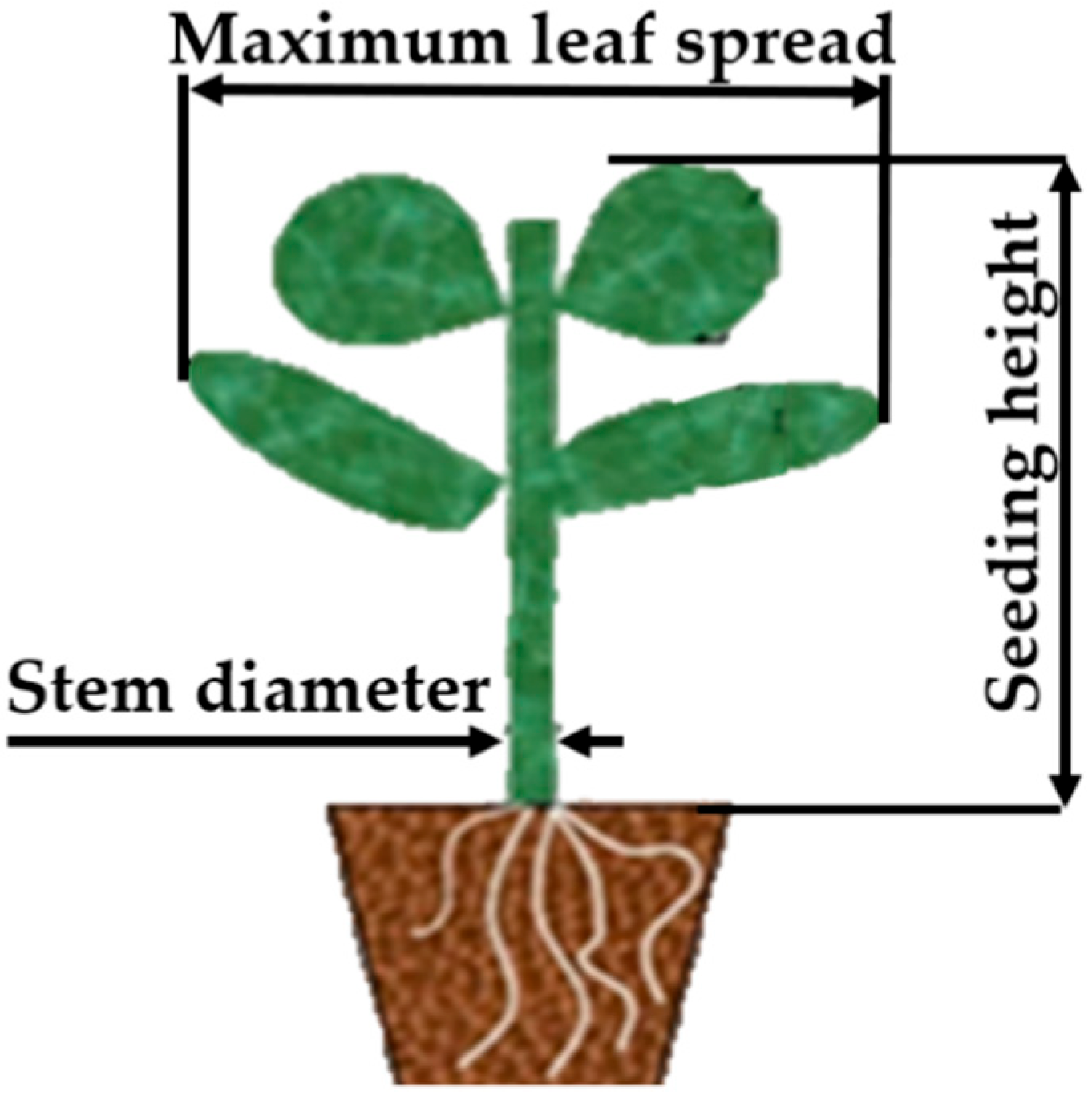
In order to accurately design the key dimensional parameters of the seedling-extraction claw and improve the versatility of the seedling-extraction mechanism, this section firstly measures the dimensional characteristics of the three kinds of vegetable potting seedlings (chillies, tomatoes, and broccoli) that are widely planted in Guangdong and suitable for mechanical transplanting, and statistically analyses their dimensional ranges. The dimensional characteristics of the test were measured using 128 potting seedlings with the same substrate ratio (3:1:1 for charcoal:perlite:vermiculite), moisture content between 50% and 60%, and age of 35 days. Measurement indexes mainly include potting height (the distance from the apex of the potting leaves to the upper plane of the potting body), maximum leaf spread (the maximum distance between the leaves of the potting seedlings when they are naturally unfolded), weight of the potting seedlings (the weight of the whole potting seedling including the potting body when it can be transplanted), and thickness of the stems (the thickness of the stems of the seedlings under the lowest leaves of the potting seedling), and the size of the potting body was defaulted to the size of the individual potting holes because the substrate filled the whole potting hole in seedling nursery. The main measurement parameters are shown in Figure 1.

2.1.2. Mantle Compression Characteristic Test

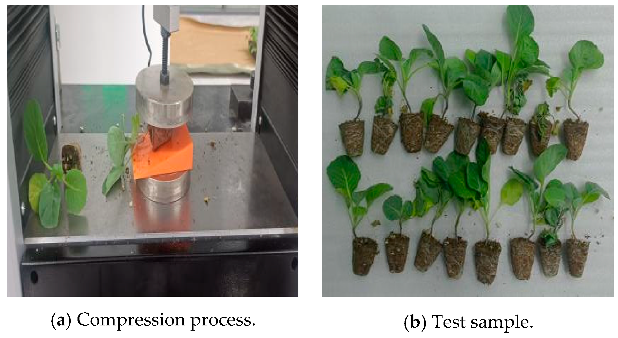
In order to accurately assess the appropriate clamping force required by the external mechanism for lifting the potting seedling and to avoid damage to the seedling due to excessive compression, it is necessary to study the compression characteristics of the potting seedling. In order to analyse the relationship between the compression resistance of the potting body and the amount of substrate deformation, compression characteristic tests were carried out on three types of potting seedlings. Before the test, the moisture content of the seedlings used for the test was determined sequentially using a halogen moisture meter (METTLER TOLEDO HE53, Shanghai, China) to ensure that it was within the specified range. The test process is shown in Figure 2: the inclined plane is fixed on the universal material testing machine (WDW-100 Jinan Chuanbai Instrument Equipment Co., Ltd., Jinan, China); the potting seedlings are placed in the centre of the inclined plane so that the potting seedlings can be parallel to the face of the compression plate; the compression plane is lowered to the height that just touches the plane of the potting; the loading speed is set to be 1 mm/s and the loading displacement is set to be 13 mm for the compression; and the test is repeated six times for each potting seedling.

2.1.3. Potting Seedling Release-Force Test

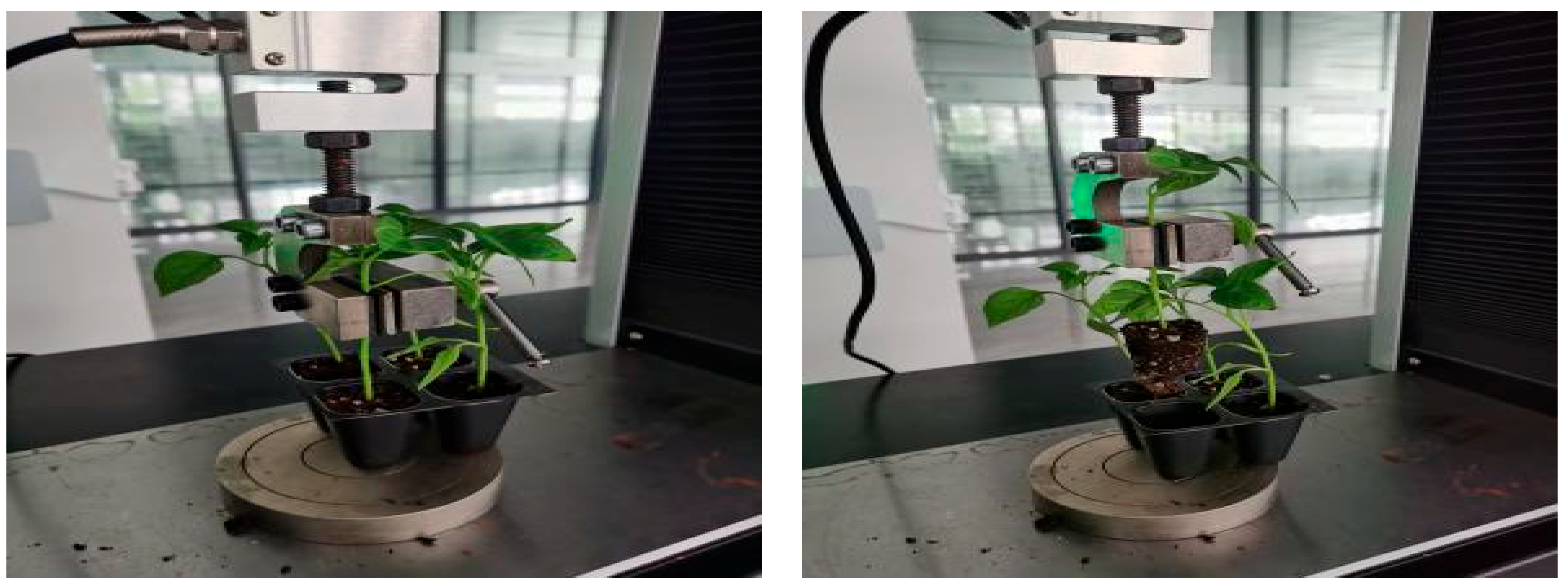
Adhesion force will be formed between the potting body and the seedling tray potting hole during the process of potting-seedling root growth. In order to provide a basis for the force analysis of seedling extraction by seedling claw, the de-disking force test for different potting seedlings was carried out. For the potting seedlings with a moisture content of about 55%, the maximum de-disking force [33] is required, so before the test we needed to control the three potting seedlings’ moisture content to ensure it remained at about 55%. The test process is shown in Figure 3. The test involves potting seedlings as a group into the neighbouring 4 holes cut from the potting tray; the use of double-sided tape means the bottom of the load table is fixed in the universal testing machine, and clamps are used to tighten the potting seedlings in the upper part of the main culm. The loading speed was set to 1 mm/s, the loading displacement was 42 mm (consistent with the depth of the potting hole), and each potting seedling experiment was repeated 6 times.

2.2. Vegetable-Seedling-Picking and -Dropping Test Materials and Equipment

The test was carried out in the teaching and research base of South China Agricultural University, and for the test we selected self-bred 128-hole trays of chilli, broccoli, and tomato potting seedlings. The substrate ratio was grass charcoal:perlite:vermiculite = 3:1:1, and the main pieces of test equipment were the seedling test stand, electronic balance, halogen moisture meter and so on.

2.3. Vegetable-Seedling-Picking and -Dropping Test Pilot Programme

The speed of seedling extraction, water content, and seedling age all affect the success of seedling extraction, and seedling age directly affects graft survival and tolerance, which in turn affects the damage rate. It was found that the damage rate of seedlings was greater at 30–40 days of age. Therefore, 30-, 35- and 40-day-old seedlings were selected for this study. Whereas moisture content is closely related to stem looseness and affects substrate loss, proper moisture control ensures smooth seedling extraction and minimises substrate loss. Therefore, potting seedlings with water content of about 45%, 55% and 65% were selected for the experiment, respectively. The extraction frequency of seedlings must balance the conveying and extraction rhythm of seedling trays, and both too-high and too-low frequencies will negatively affect the efficiency and success rate. Meanwhile, during the pre-commissioning process, it was found that due to the increase in the end-effector, when the seedling extraction speed exceeds 50 r/min, the mechanism will produce a strong resonance phenomenon.
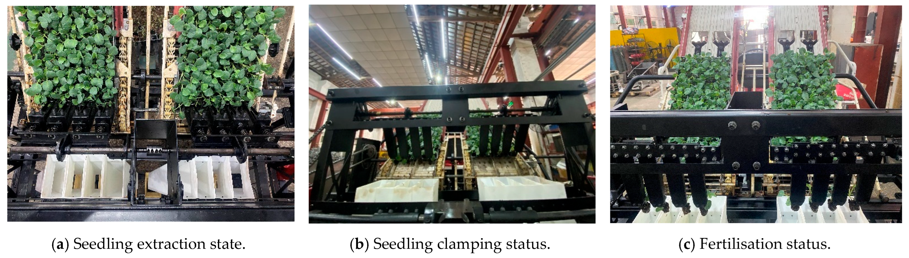
In summary, a three-factor, three-level orthogonal test was carried out with seedling-picking speed, potting water content and seedling age as the influencing factors, and the levels of the test factors were selected, as shown in Table 1. The test was carried out using broccoli potting seedlings with poor root entanglement, and a total of nine groups of tests were conducted, with 64 seedlings taken in each group of tests. The test process is shown in Figure 4.

2.4. Vegetable-Seedling-Picking and -Dropping Test Methods and Evaluation Criteria

According to the technical indexes proposed in JB/T10291-2013 [34] Industry Standard for Dryland Transplanting Machinery, taking the seedling-picking success rate Y1 and potting breakage rate Y2 as evaluation indexes, the seedling-picking performance test is carried out for the seedling-picking and -dropping mechanism. Under the condition of selecting the optimal combination, the seedling-picking performance test was carried out for tomatoes and broccoli to verify the seedling-picking performance of the seedling-picking and -dropping mechanism for different types of potting seedlings.
The evaluation indexes are calculated as shown in Equations (1) and (2):
Y 1 = N N f N × 100 %
where N is the total number of potting seedlings and Nf is the number of seedlings not removed.
Y 2 = M 0 M 1 M 2 M 0 M 1 × 100 %
where M0 is the total weight of potting seedlings, g; M1 is the weight of net seedling disc, g; and M2 is the weight of potting seedlings after taking and casting seedlings, g.

3. Results

3.1. Results of Research on Basic Physical Characteristics of Potting Seedlings

3.1.1. Results of Pot Seedling Dimensions

The potting height, maximum leaf spread, seedling stem length and seedling weight of each potting seedling were measured after the completion of the experiment and the results are shown in Table 2.
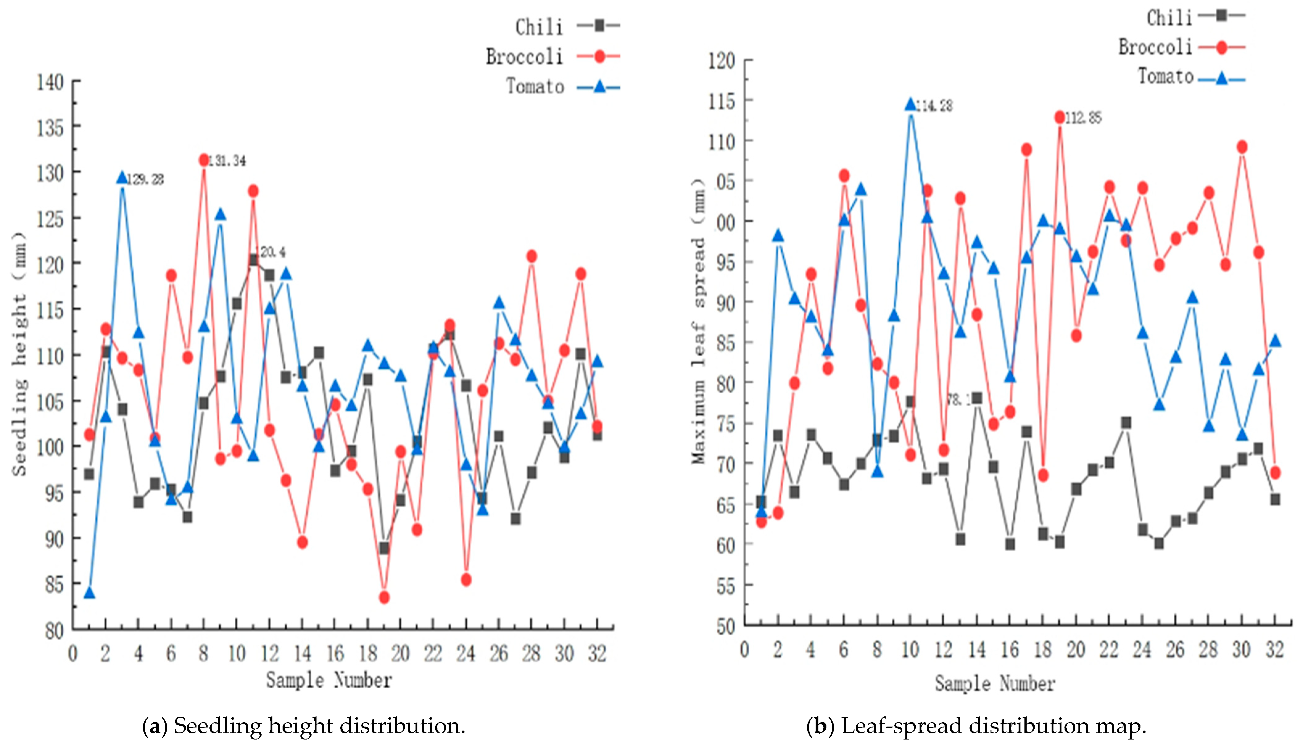
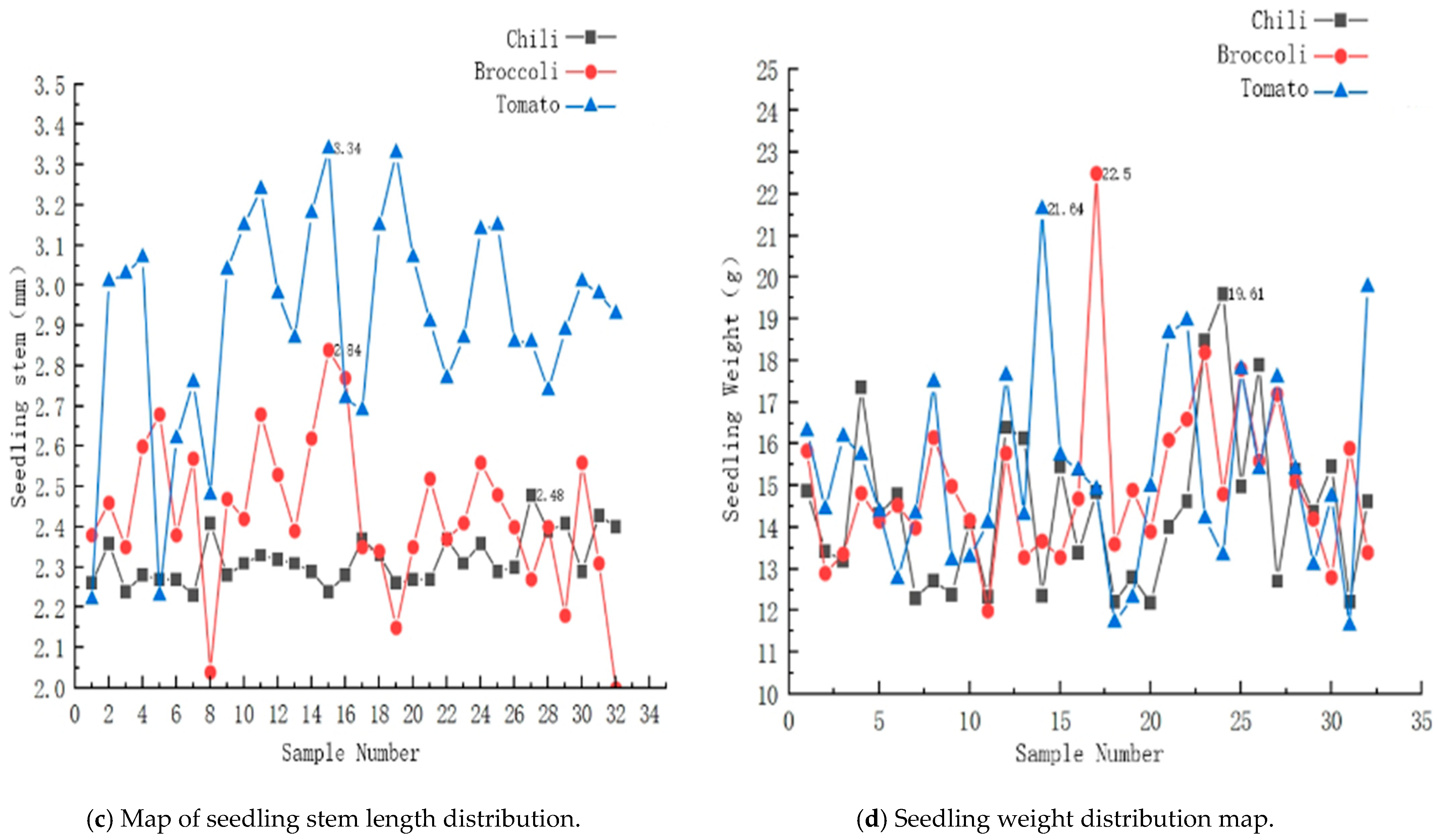
In order to observe more intuitively the differences between the test indicators for the three kinds of potting seedlings, the parameters were compared horizontally, and the results are shown in Figure 5.

3.1.2. Results of Mantle Compression Characteristic Test

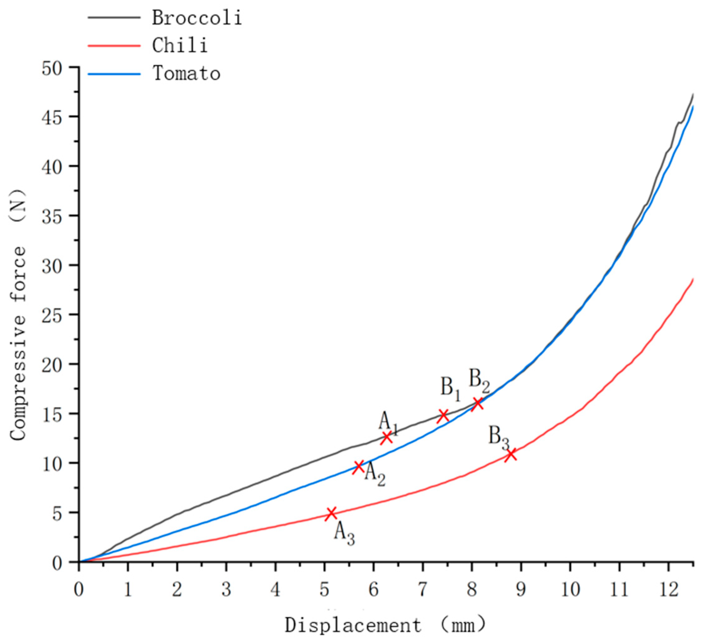
The results of the six trials for each potting seedling were imported into Origin 2024 software to generate curves, and the results were exported to generate a comparison plot, as shown in Figure 6.
From the curve in the Figure 6, it can be seen that the potting body in the process of being compressed, the deformation variable and the compression force have a nonlinear relationship. The three potting-body-compression-resistance characteristics show the following pattern: broccoli > tomato > chilli. It can be shown from the analysis that, after point B, the potting body exhibits the compaction state, the compression force increases sharply, the root system appears obvious fractured, and the potting body cannot rebound to the initial state after unloading the pressure, which is not conducive to the potting seedling’s growth in the later stage. Point B is the yield point of the potting body; at this time, the compression displacements of chillies, tomatoes, and broccoli are 8.8, 8.11, and 7.45 mm, respectively, and the compression force is 11, 16.2, and 14.85 N, respectively. From the above analysis, it can be seen that the compression displacement of the seedling-clamping claw should be less than the minimum compression displacement of the mantle body of 7.45 mm, and that the clamping force is less than 11 N.

3.1.3. Results of Potting-Seedling-Release-Force Test

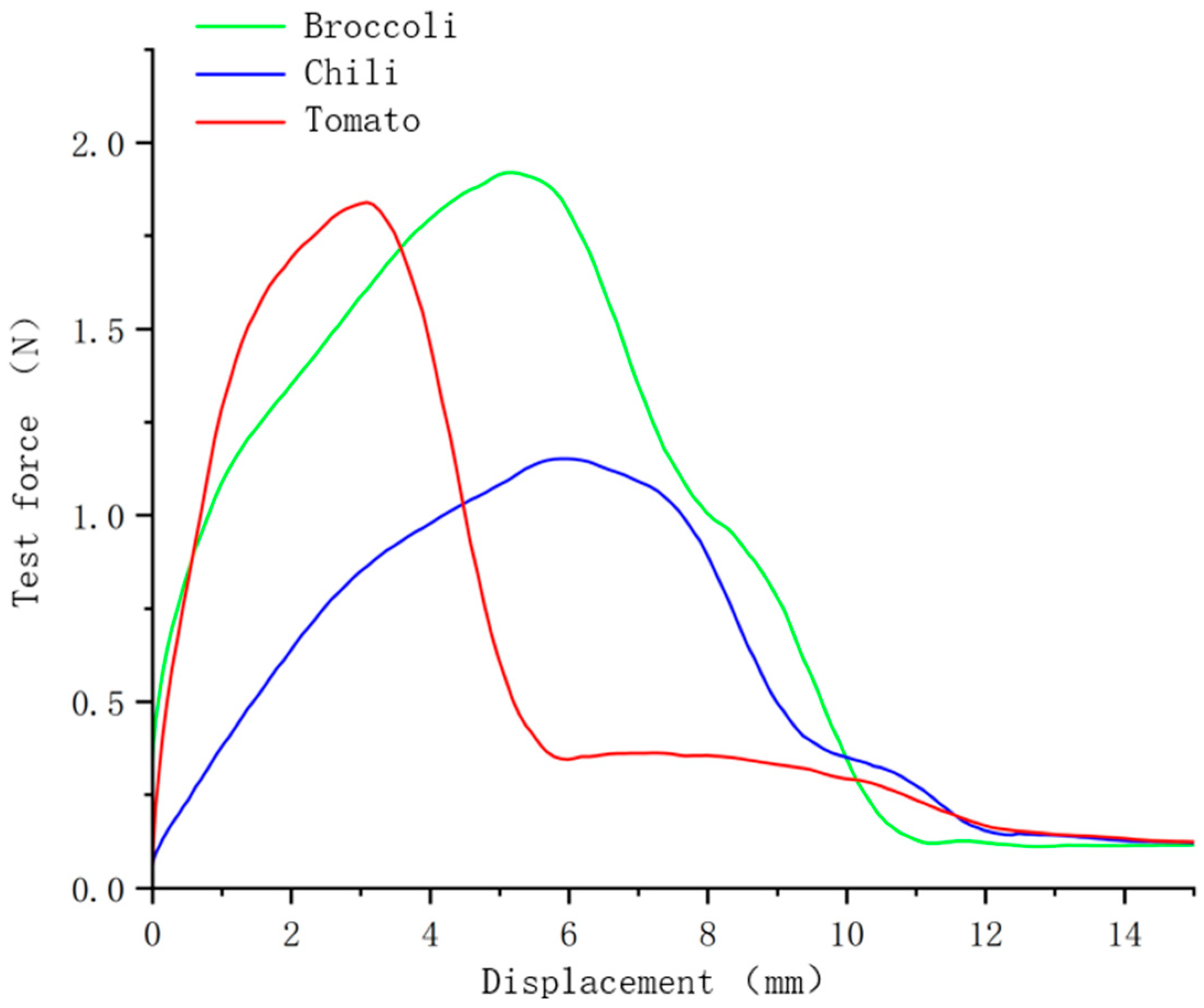
As can be seen from Figure 7, the magnitude of the dislodging force for chillies, tomatoes and broccoli was broccoli > tomatoes > chillies, and the peak dislodging force was 1.2, 1.8 and 1.9 N, respectively.

3.2. Structure and Working Principle of Seedling-Picking and -Dropping Mechanism

Design of the Seedling Planting Institution Plan

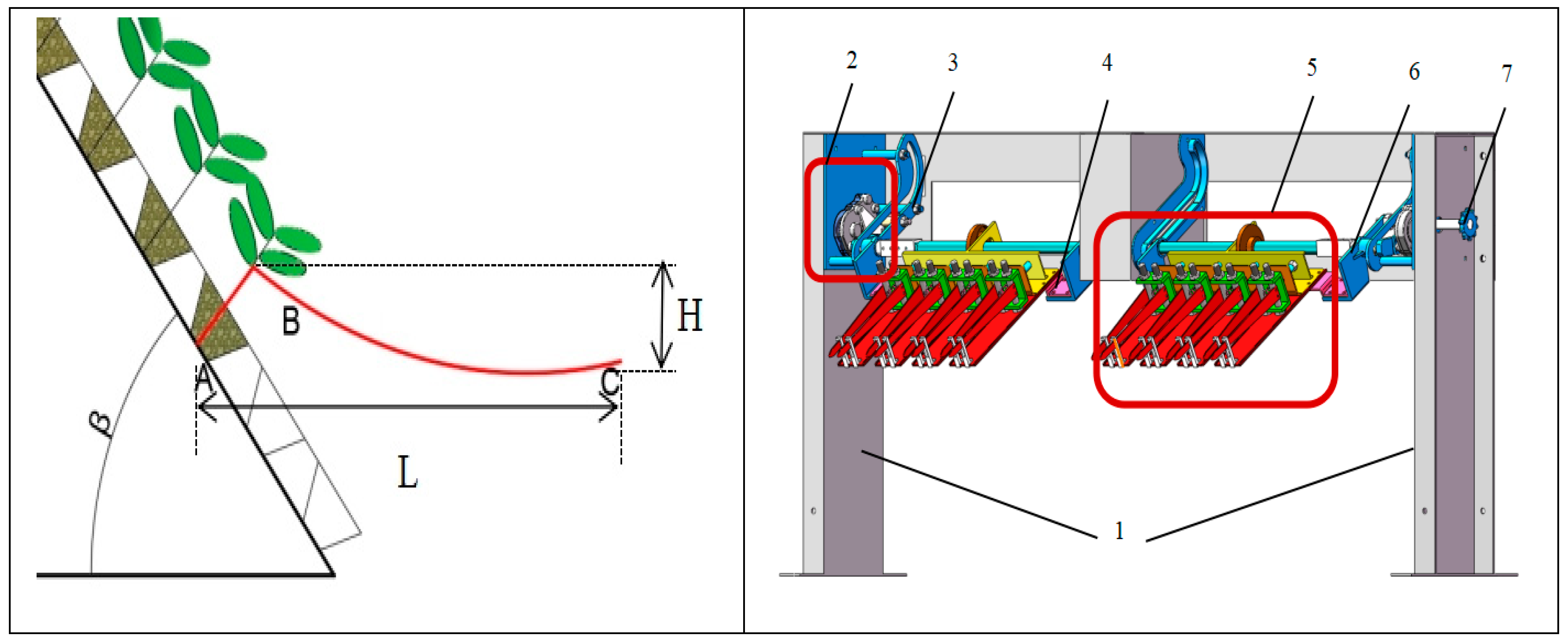
In order to meet the “reciprocating common track” type of seedling trajectory, we needed to solve the problem of the low efficiency of single-plant seedling transfer, clamping when the bowl is fragile, and instability when holding the seedling due to vibration. In this paper, a whole-row mechanical two-jaw pick-and-place mechanism is proposed for 128-hole potting trays, and the seedling removal trajectory and overall structure are shown in Figure 8.
When working, the power is transmitted from the power output shaft of the motor to the driving sprocket through the chain; the sprocket is fixed on the rotating centre of the gearbox of the planetary wheel system-linkage mechanism; the sprocket rotates to drive the planetary frame to rotate around the sun wheel; and the power is transmitted through the planetary wheel system-linkage mechanism in the planetary wheel system to make the sliding pin axle perform a reciprocating straight-line motion at the same time as the sliding pin axle rotates around its own axis. At the same time, the slide pin shaft rotates around its own axis, which is due to the constraints of the two sides of the track slot on the slide pin shaft, and the clamping mechanism in the planetary wheel system-linkage mechanism under the drive moves along the sliding track slot, so as to achieve the ideal seedling trajectory designed in the previous section. Four end-effectors are spaced on the end-effector mounting plate, and when the mechanism moves to the seedling picking point, the clamping mechanism clamps the seedling, picking it up, and when it reaches the seedling throwing point, the clamping mechanism loosens to complete the seedling throwing.

3.3. Planetary Wheel System-Linkage Mechanism Design

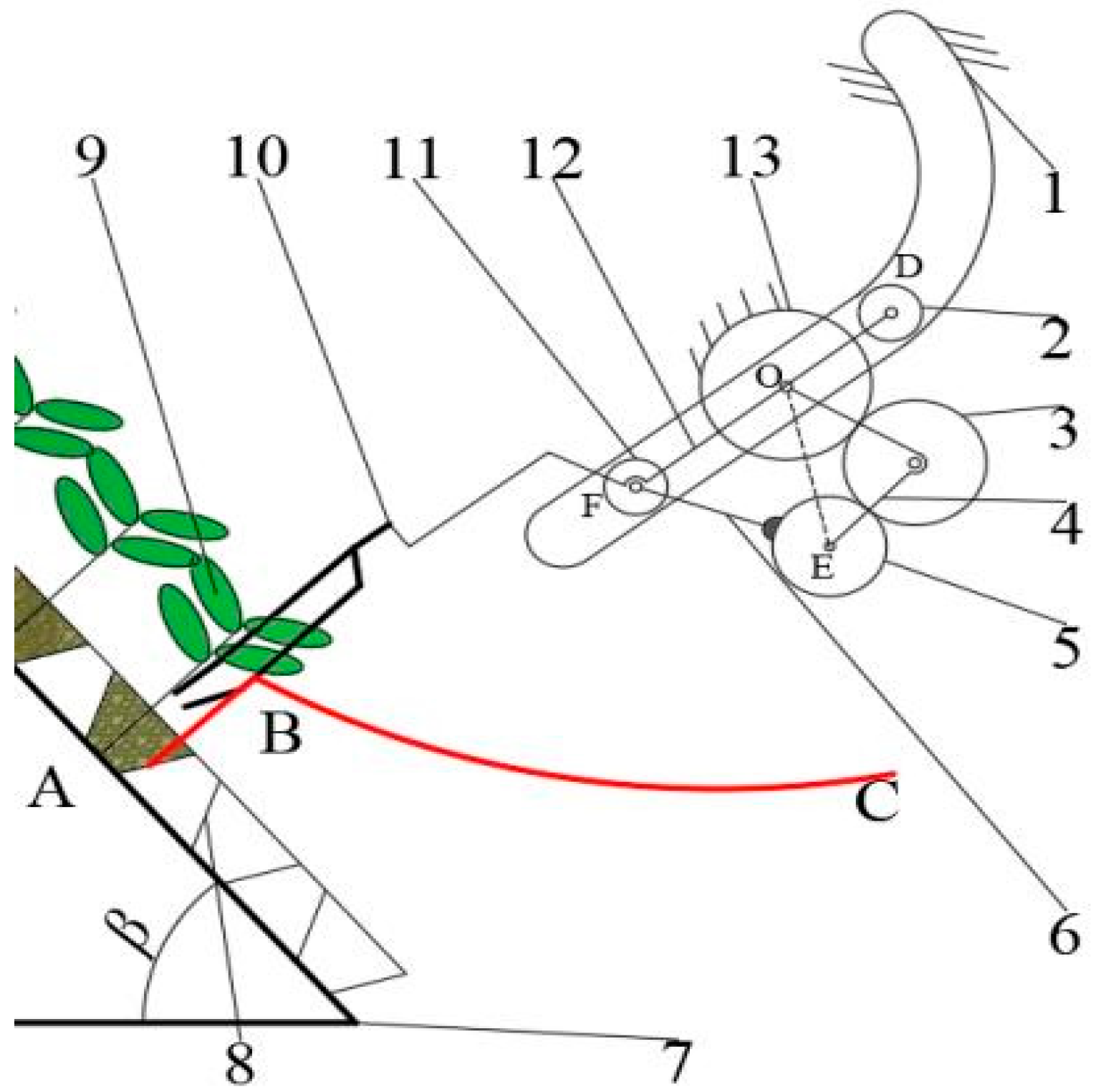
The planetary wheel system-linkage mechanism is the key to the seedling-picking and -dropping mechanism achieving the seedling-picking trajectory movement. As shown in Figure 9, it mainly consists of track groove1, slide pin2, intermediate wheel3, planetary frame4, planetary wheel5, connecting rod6, end-effector10, slide pin shaft11, slide rod12, sun wheel13 and other components. The planetary wheel system consists of three round gears, of which the sun wheel is fixed, driven by a drive shaft with the same axis as the sun wheel and fixed on the planetary frame to drive the planetary frame to rotate clockwise around the sun wheel. The intermediate wheel is meshed with the sun wheel and planetary wheel drive, respectively, and the connecting rod and the planetary wheel on the axle have a solid connection. The other end of the sliding pin with the axle is hinged at the point F, and through the sliding rod and the sliding pin it is fixedly connected.
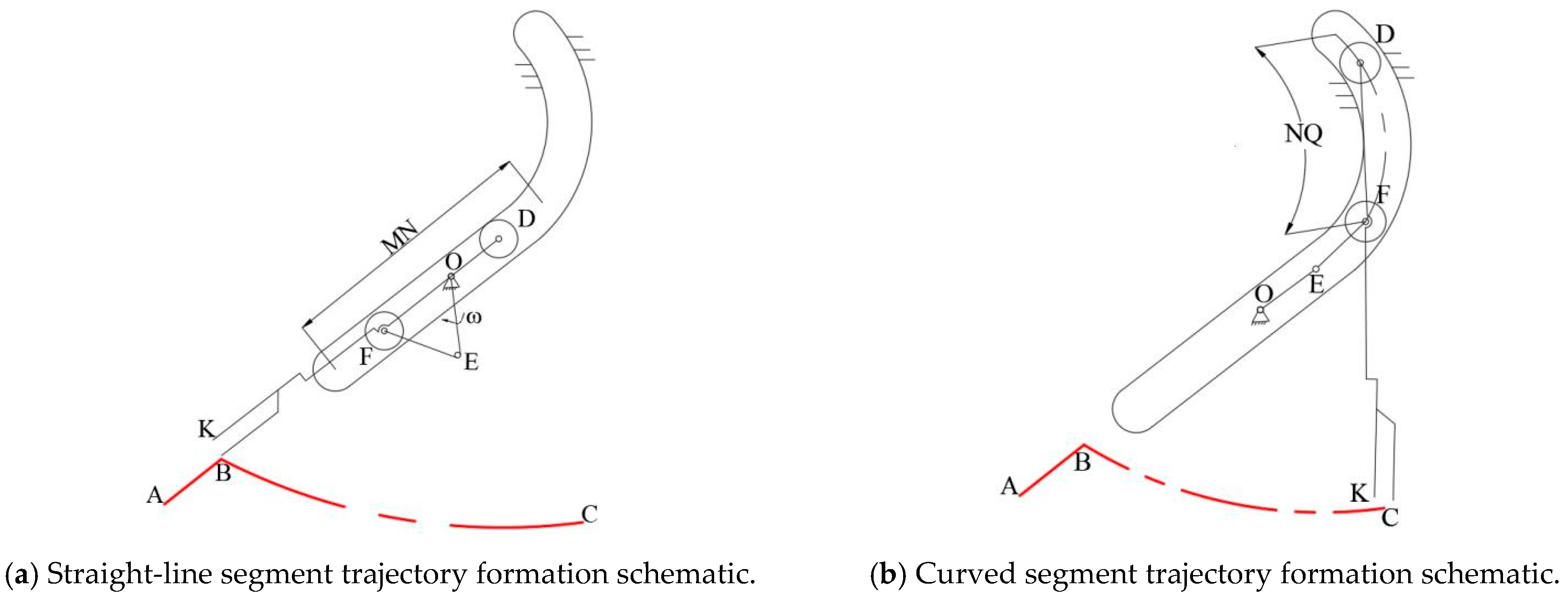
The specific principle of trajectory formation is as follows, as shown in Figure 10a: in the time taken for the end of the seedling claw K point to reach the beginning of the straight-line trajectory of the B point, the planetary wheel system–connecting rod mechanism with angular velocity ω performs a clockwise rotation. The planetary carrier is simplified as a crank OE, and the sliding pin shaft and connecting rod EF form a crank-slider mechanism. When the crank rotates clockwise, the sliding pin shaft makes reciprocating linear motion along MN. At this time, the sliding rod FD and the sliding pin are both located in the straight-line section MN interval, so it can form a straight-line trajectory AB along the direction of MN; due to the sliding rod being rigidly connected to the end-effector and hinged in the sliding pin shaft at the point F, when the crank continues to rotate, this drives the sliding rod FD and the sliding pin D to enter the curved segment of the trajectory groove NQ, as shown in Figure 10b. Due to the limitations of the curved section of the trajectory slot, the end-effector swings with point F as the centre, and the end-point K forms the curved part of the trajectory along BC so that the end-effector tip K forms the planned seedling-taking trajectory ABC.
In order to make the sliding pin form a fixed reciprocating motion in the trajectory slot straight-line MN, it needs to meet the following conditions: crank OE and connecting rod EF need to be equal in length; connecting rod EF and crank OE rotate in opposite directions; connecting rod EF moves around the point E, and the rotational speed is two times that of the crank so that when the crank is rotating the OE and EF always constitute an isosceles triangle; and the EF, with a rotational speed of −2 ω, is rotating around point E of the counterclockwise rotation around the point O at the same time, with a clockwise rotation.

3.3.1. Calculation of Degrees of Freedom

In order to determine that the planetary wheel system-linkage mechanism has a unique trajectory, it is necessary to calculate the degrees of freedom of the mechanism, which belongs to the planar mechanism, and the degrees of freedom can be calculated by Equation (3):
F = 3 n 2 P l P h F
where F is the degree of freedom, n is the number of active members, Pl is the number of low subs, Ph is the number of high subs, and F’ is the number of virtual constraints. Considering the sliding pin axis as a hinge point in the mechanism, the number of active members is 4, the number of low vice is 5, and the trajectory of the sliding pin and the sliding bar at point D coincide, so the virtual constraint is 1, and the degrees of freedom are calculated as follows:
F = 4 × 3 2 × 5 0 1 = 1
The degree of freedom F = 1 means that the mechanism can form a uniquely determined seedling-taking trajectory.

3.3.2. Kinematic Analysis of Planetary Wheel System-Linkage Mechanisms

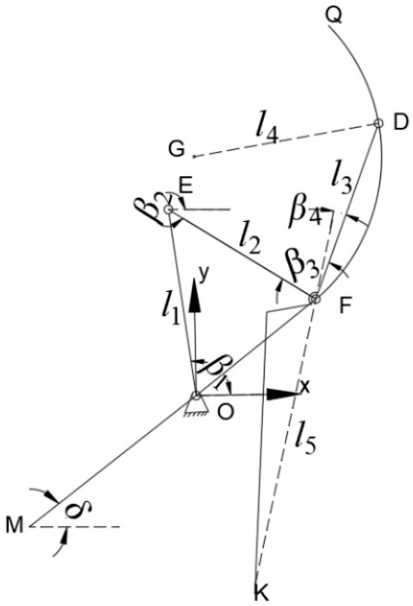
In order to obtain the key parameters of the trajectory slot and of each gear, the kinematic model of the planetary wheel system-linkage mechanism is established by the vector modelling method, and the key point displacement, velocity and acceleration parameters are analysed. In order to simplify the analysis, the planetary wheel system-linkage mechanism is further simplified, as shown in Figure 11, with the rotation centre O of the sun wheel as the origin, and the horizontal and vertical directions as the X-axis and Y-axis to establish the right-angle coordinate system, and simplify the sliding pins and the sliding pin axis as the slider and the articulation point, respectively. The kinematic analysis is carried out with clockwise rotation as the positive direction and crank speed as ω. The relevant symbols involved in the analysis process are explained in Table 3.
From the figure above, we can see that in the vector triangle, O E + E F = O F , Converting this into analytical form gives the equation for the displacement of the point E as:
x E = l 1 cos β 1 y E = l 1 sin β 1
The equation for the displacement of point F is:
x F = l 2 cos β 2 + x E y F = l 2 sin β 2 + y E
From the law of motion of the differential wheel system:
β 2 = 2 β 1
In the two triangles formed by the radius l4 of the circular arc slide, we use one as the hypotenuse and the slide bar DF as the hypotenuse, respectively, both satisfy the following equations:
x D x G 2 + y D y G 2 = l 4 2 x D x F 2 + y D y F 2 = l 3 2
Collating the above equation and simplifying the representation, let
a = 4 y F y G 2 + x F x G 2 b = 8 y G x F x G y F y G 1 2 d x F x G + x G y F y G 2 c = 4 y F y G 2 x G 2 + y G 2 l 4 2 + 1 4 d 2 d y F y G d = l 4 2 l 3 2 + x D 2 + x F 2 x G 2 + y G 2
Bringing the above equation into the calculation results gives the displacement equation for point D as:
x D = b b 2 4 a c 2 a y D = d 2 x D x F x G 2 y F y G
Take the displacement equation for the point K at the end of the seedling claw as:
x K = l 5 cos β 3 + β 4 + π + x F y K = l 5 sin β 3 + β 4 + π + y F
where β3 is the angle of rotation of the slide bar DF with respect to the connecting rod EF, which can be expressed as:
β 3 = arctan y D y F y D y F
In order to obtain the velocity model of the critical point in the planetary wheel system-linkage mechanism, the first order derivative of time is taken for the displacement equation, then the velocity equation of point E is:
x E = l 1 cos β 1 y E = l 1 sin β 1
The velocity equation for point F is:
x F = l 2 cos β 2 + x E y F = l 2 sin β 2 + y E
The velocity equation at point D is:
x D = b + b 2 4 a c a b + b 2 a c 2 a c b 2 4 a c 2 a 2 y D = d 2 x D x F x G + d y F y G x F x G 2 d + 4 x D y F y G 4 y F y G 2
The velocity equation for point K is:
x K = x F l 5 sin ( β 3 + β 4 + π ) y K = y F + l 5 cos ( β 3 + β 4 + π )
The acceleration equation for the trajectory of point K can be obtained by adding the derivative of time to Equation (14)
x K = x F l 5 cos ( β 3 + β 4 + π ) y K = y F l 5 sin ( β 3 + β 4 + π )

3.3.3. Design of Key Parameters

Based on the kinematic analysis of the planetary wheel system-linkage mechanism, it was found that the key point motion of the seedling-picking and -dropping mechanism was jointly influenced by several parameters such as rod lengths l1, l2, l3 and the mechanism turning angle, etc. Since the mechanism mounting angle was the same as the seedling-picking angle, and the angle of seedling picking had already been determined, the length of the crank OE, l1, the length of the linkage EF, l2, the length of the sliding bar DF, l3, and the trajectory groove were selected, along with the radius of the circular arc slide, l4, as design variables, where the crank and connecting rod lengths are equal, i.e.,:
l 1 = l 2
X = x 1 , x 2 , x 3 , x 4 T = l 1 , l 2 , l 3 , l 4 T
The compactness of the mechanism is essential and is allowed for during the design process, and the following range of design variables can be determined based on the spatial configuration requirements of the planetary wheel system-linkage mechanism:
s . t . 20 < x 1 < 50 x 2 = x 1 50 < x 3 < 80 x 1 < x 4 < x 3
Determine the optimisation objective function according to the requirements of the trajectory planned in Section 3.1.2 and take the length of the seedling segment AB as 70 mm, f 1 ( x ) = x A x B 2 + y B y A 2 70 ; seedling trajectory length L > 300 mm, f 2 x = x C x A 300 ; and seedling trajectory height H > 80 mm, f 3 x = y B y C 80 .
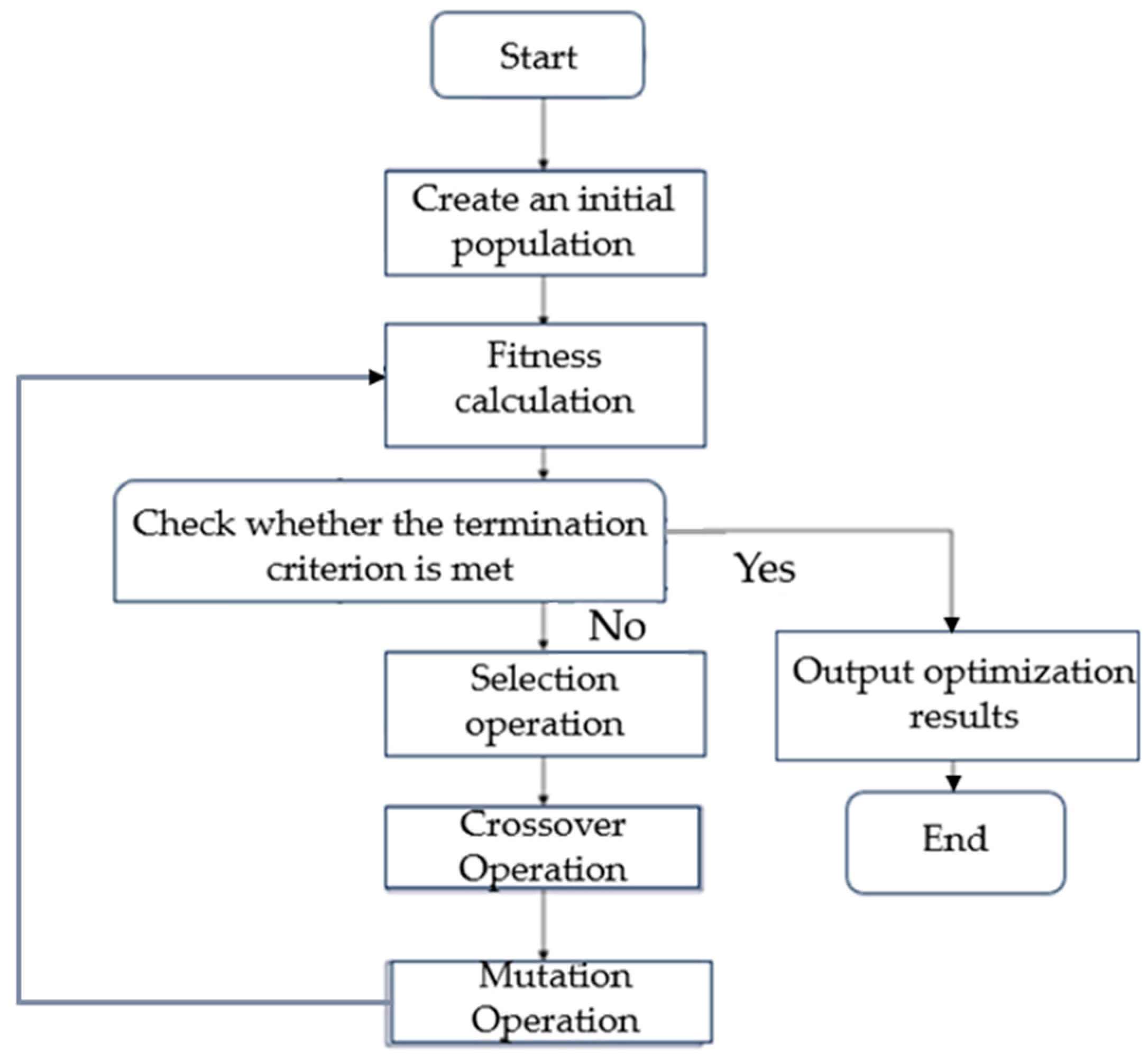
From the objective function and design variables, it can be seen that there is a nonlinear relationship between the parameters of the mechanism and the objective, which belongs to the multi-objective nonlinear optimisation problem. For this kind of optimisation problem, Matlab.19 software provides a variety of optimisation algorithms, and through the comparison and analysis of a variety of algorithms, when preparing this paper we decided to use genetic algorithms for solving. A genetic algorithm can effectively avoid generating local optimal solutions, has a strong ability to search for global optimal solutions, and can adapt to a wide range of constraints; the operation flow is shown in Figure 12 [35]. This illustrates optimisation by genetic algorithm with multiple iterations.
The results are that the length of crank OE l1 = 34 mm, the length of connecting rod EF l2 = 34 mm, the length of slide bar DF l3 = 70 mm, and the radius of the circular slide of the track slot l4 = 45 mm.

3.3.4. Determination of Gear Parameters

Since there is a planetary carrier that can be rotated in the planetary wheel train-linkage mechanism, the planetary wheel train belongs to the differential wheel train, which can be known according to the formula for calculating the transmission ratio of the differential wheel train, which should be −1. Combined with the analysis of the necessary conditions for trajectory formation in Section 3.1.2, the following equation can be obtained:
2 ω O E = ω E F
i 13 H = 1 i 31 H = 1 Z 1 Z 3 = 1
From the above formula, it can be seen that the planetary wheel system in the sun wheel and planetary wheel steering need to move in opposite directions, and that the sun wheel and planetary wheel tooth number ratio is 2:1. Using this, combined with the optimisation results above, we can obtain the gear parameters that need to be satisfied:
a 1 = Z 1 + Z 2 × m 2
a 2 = Z 2 + Z 3 × m 2
l 1 = a 1 2 + a 2 2 2 a 1 a 2 cos γ
Z 1 = 2 Z 3
where a1 is the centre distance between the sun wheel and the intermediate wheel; a2 is the centre distance between the intermediate wheel and the planetary wheel; Z1 is the number of teeth of the sun wheel; Z2 is the number of teeth of the intermediate wheel; Z3 is the number of teeth of the planetary wheel; l1 is the length of the crank OE; and γ is the angle between a1 and a2.
The intermediate wheel in the mechanism only plays the role of commutation, which can be regarded as a constant, so the above equations can be solved. The results show the rounding of the number of teeth of the sun wheel Z1 = 24, the number of teeth of the intermediate wheel Z2 = 18, the number of teeth of the planetary wheel Z3 = 12, the modulus m = 1.5, and the angle of the wheel system γ = 76°.

3.4. Clamping Mechanism Design

3.4.1. Composition and Working Principle of Clamping Mechanism

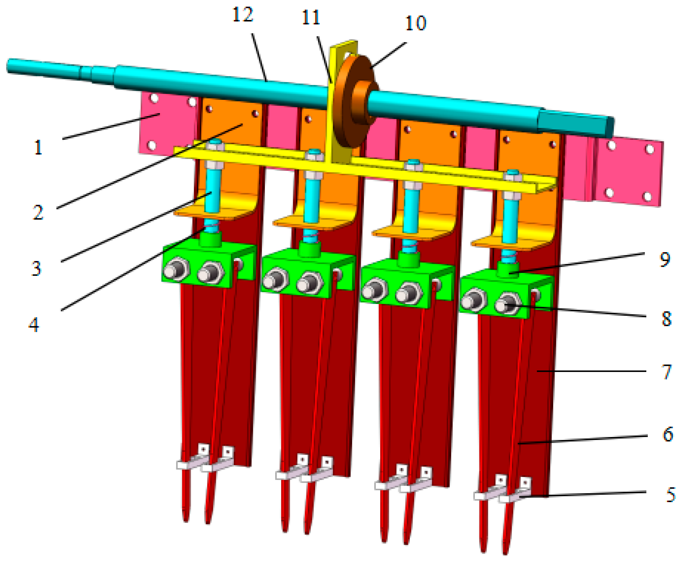
The structure of the clamping mechanism is shown in Figure 13, which mainly consists of an end-effector mounting plate1, a connecting plate2, a tensioning tie rod3, a spring4, a limit block5, a seedling-picking claw6, a fixed plate7, a rotating shaft8, a square block9, a seedling-clamping cam10, a pulling plate12 and a cam spindle12, wherein the connecting plate and the tensioning tie rod, the seedling-picking claw, the limit block, the square block, the fixed plate and the rotating shaft together form the end-effector.
The clamping mechanism is fixedly mounted on the planetary wheel system-linkage mechanism, and the cam-rotating shaft is fixedly connected to the slide pin shaft of the planetary wheel system-linkage mechanism through the square tube of the linkage. The planetary wheel system-linkage mechanism of the slide pin shaft works through the connecting shaft square tube output continuous rotation drive cam rotary axis rotation, at the same time clamping the seedling cam following the cam rotary axis rotation. When the take-and-throw seedling mechanism is inserted into the potting body, the clamping seedling cam turns to push the range stage, and the pull plate promotes the tensioning tie rod and the square block downward movement, which is due to the seedling claw moving through the limit block through the promotion of the seedling claw around the rotary axis movement. The two sides of the seedling claw, with the different support force and direction of the limit block, clamps the mantle. When the mechanism reaches the seedling casting point, the cam enters the return stage, the pull plate moves upward rapidly, the two sides of the seedling extraction claws spring back to loosen the potting body, and at the same time the limit block assists in pushing the seedling downward, completing the seedling extraction and casting action.

3.4.2. Analysis of End-Effectors

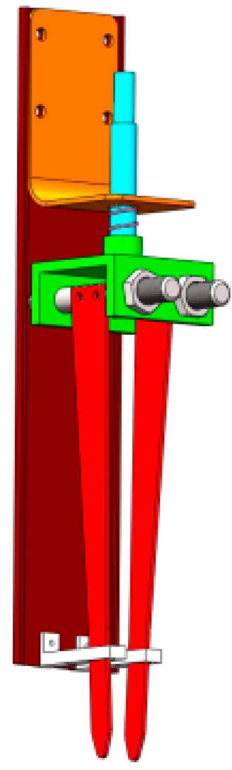
The end-effector is responsible for cooperating with the seedling clamping cam to complete the grasping and releasing of the potting seedlings, and its structure has an important impact on the effect of seedling taking. According to the number of claws, the end-effector can be divided into two claws, three claws, four claws and other forms. Through the preliminary research work on the potting seedlings, in the process of being taken out of the force analysis, we found that the two-claw end-effector made it easy to clamp the potting seedling and reduce potting damage; simple structure and a compact space layout can effectively improve the potting seedling survival rate, so in this paper we decided to recommend the use of the two-jaw end-effector, as shown in Figure 14.

3.4.3. Design of Key Dimensional Parameters of the Pick-Up Claw

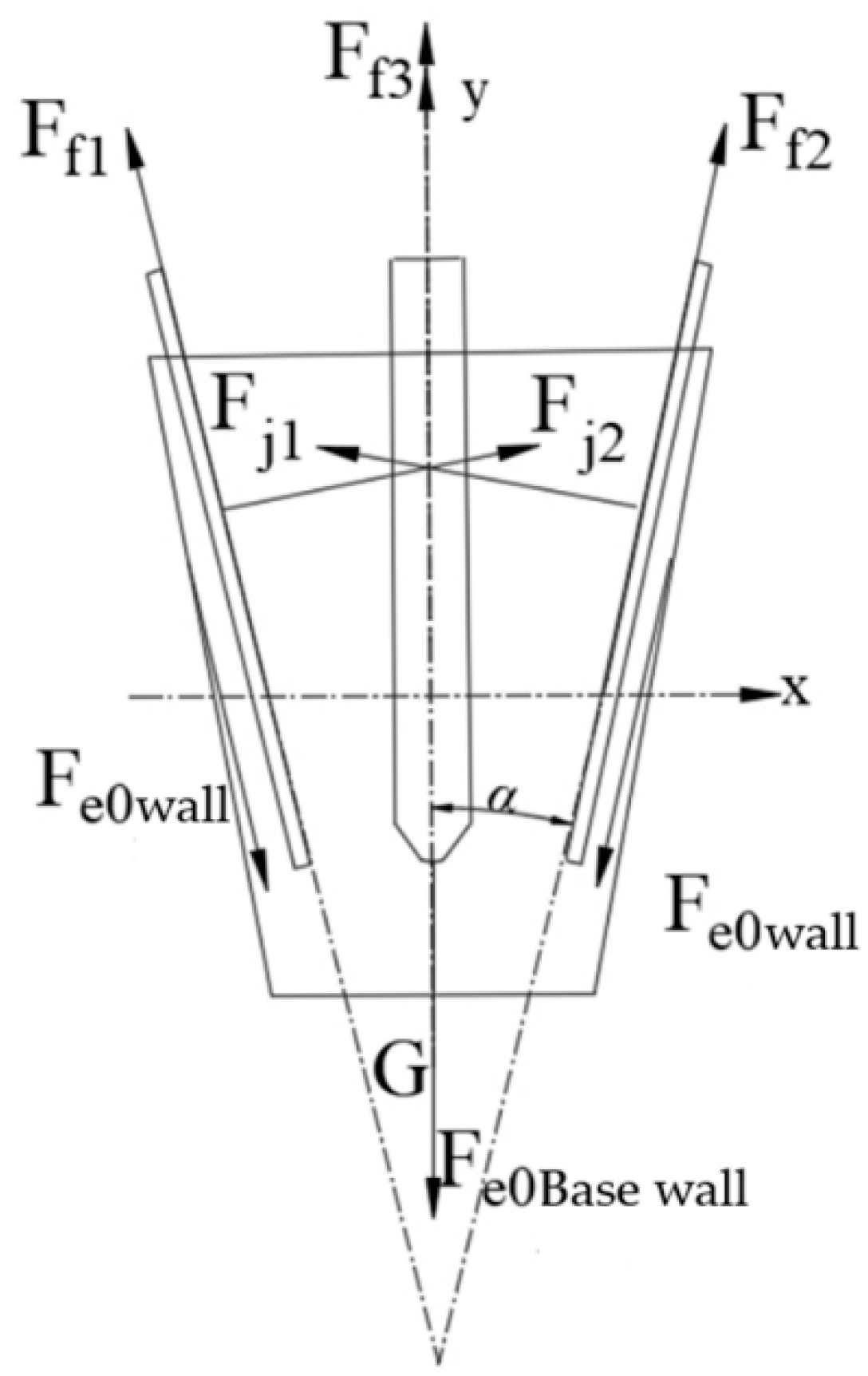
During the potting seedling grasping process, the force exerted by the seedling extraction claw on the potting seedling will directly affect the success of seedling extraction. Therefore, it is necessary to analyse the clamping force of the seedling extraction claw, and to investigate the influence of the parameters of the seedling extraction claw on the force used during the seedling extraction so as to determine the size of the key parameters of the seedling extraction claw. The rear seedling extraction claw has no clamping effect on the potting body; therefore, at the moment when the seedling extraction claws clamp the mantle and pull it outward, we considered the friction between the clamping force of the two seedling claws and the pot. As shown in Figure 15, the force analysis of the mantle along the direction of pulling out shows the mantle can be successfully removed under the following force equilibrium conditions:
F f 1 + F f 2 cos α + F j 1 + F j 2 sin α = G + 2 F e 0 wall cos α + F e 0 b a s e w a l l
F f 1 = F f 2
F j 1 = F j 2
where Ff1, Ff2, and Ff3 is the friction force of the seedling extraction claw on the mantle, N; Fj1 and Fj2 is the normal clamping force of the seedling extraction claw on the mantle, N; G is the gravitational force of the mantle seedling in the direction of pulling out, N; Fe0wall is the combined friction and adhesion force generated by the wall.N;Fe0base wall is force generated by the bottom, N and α is the angle of seedling clamping by the seedling extraction claw, °.
In Equation (29), the friction force of the seedling extraction claw on the potting body mainly consists of the slip resistance between the potting body and the seedling extraction claw and the slip resistance between the substrate particles, which can be expressed as:
F f = f a + f b
f a = μ F j
f b = μ σ s
s = h 1 m
where fa is the slip resistance between the mantle and the seedling claw, N; fb is the slip resistance between the substrate particles, N; μ is the coefficient of friction of 0.3; σ is the adhesion force between the substrate compression strength, that is, the mantle compressive strength of 9.5 kpa, Pa; s is the clamping area of the seedling claw, mm2; h1 is the insertion depth of the seedling claw, mm; and m is the width of the seedling claw, mm.
The above formula can be obtained after the collation of the clamping force and seedling claw parameters that influence the relationship using the equation:
F j = G + 2 F e 0 wall cos α + F e 0 b a s e w a l l μ σ h 1 m cos α 3 μ cos α + sin α
After analysis, the clamping force of the seedling extraction claw is mainly related to the gravity of the potting seedling G, and the compressive strength of the potting body σ is 9.5 kpa, the coefficient of friction μ is 0.3, the clamping angle α, the seedling claw clamping depth h1 and the width of the seedling claws m. Among them, the gravity, compressive strength and friction coefficient are all related to the characteristics of the substrate, so using the premise of a certain insertion depth, the clamping angle α of the seedling extraction claw and the width of the seedling extraction claw m are the key parameters affecting the success of seedling extraction.
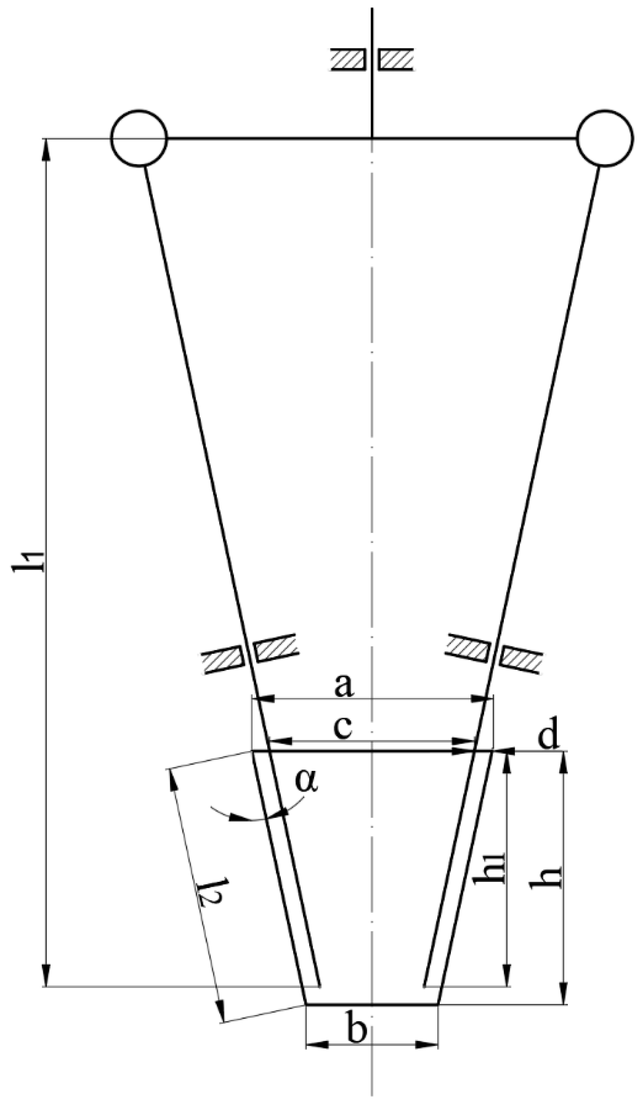
According to the above force analysis results, in order to meet the requirements of seedling extraction, seedling extraction claw parameters need to meet the following constraints. See Figure 16 for the key parameters of the seedling extraction claw schematic diagram.
By analysing the force when clamping seedlings, it can be seen that the insertion depth of the seedling extraction claw and the size of the seedling extraction force are positively correlated, in order to prevent the potting seedling from falling. When taking seedlings, the seedling extraction claw needs to be inserted into the potting hole by more than half of the depth of the potting hole, that is:
1 2 h < h 1 h > h 1
where h is the depth of potting hole, mm.
This design is mainly for the upper size of 30 × 30 mm, the lower size of 18 × 18 mm, the depth of 42 mm and the 128-hole potting tray design, so the insertion depth of the seedling extraction claw h1 need to meet the criteria 21 < h1 < 42 mm for the three different specifications of the potting tray. In Section 2.1, the measurement results show that the depth of potting holes is in the range of 36 < h < 42 mm, so in order to make the end-effector in the subsequent optimization process, we can adapt to different specifications of the tray, taking the depth to be 35 mm h1. In order to make the end-effector in the subsequent optimisation process, we can adapt to different specifications of the seedling tray, taking the seedling claw insertion depth h1 as 35 mm.
When the seedling claw insertion depth is certain, in order to avoid the seedling claw insertion being too short and the claw being unable to clamp the potting seedling, the seedling claw length l2 should be satisfied:
l 2 h 1 cos α
where α is the inclination angle of the inclined disc, °.
From the force analysis above, it can be seen that in the experiments leading up to this paper we used the seedling claw deformation to lift the potting body up. When the width of the seedling claw is too small, it is easy to break the seedling; when the width of the seedling claw is too large, it is easy to touch the potting seedling’s stems and leaves; and when it is inserted, it is easy to cut off the roots, so there is a phenomenon of injuring the seedling and injuring the root. Therefore, the seedling claw is designed to have a width of 6 mm, a thickness of 1.5 mm, and a length of 180 mm. In order to reduce the damage to the potting body, the seedling claw needs to be as close as possible to the edge of the potting body when it is inserted [34]. In order not to hurt the main root centre area, the insertion margin was taken as 2 mm, and the insertion depth was 35 mm.

3.5. Seedling Removal Test Results and Analyses

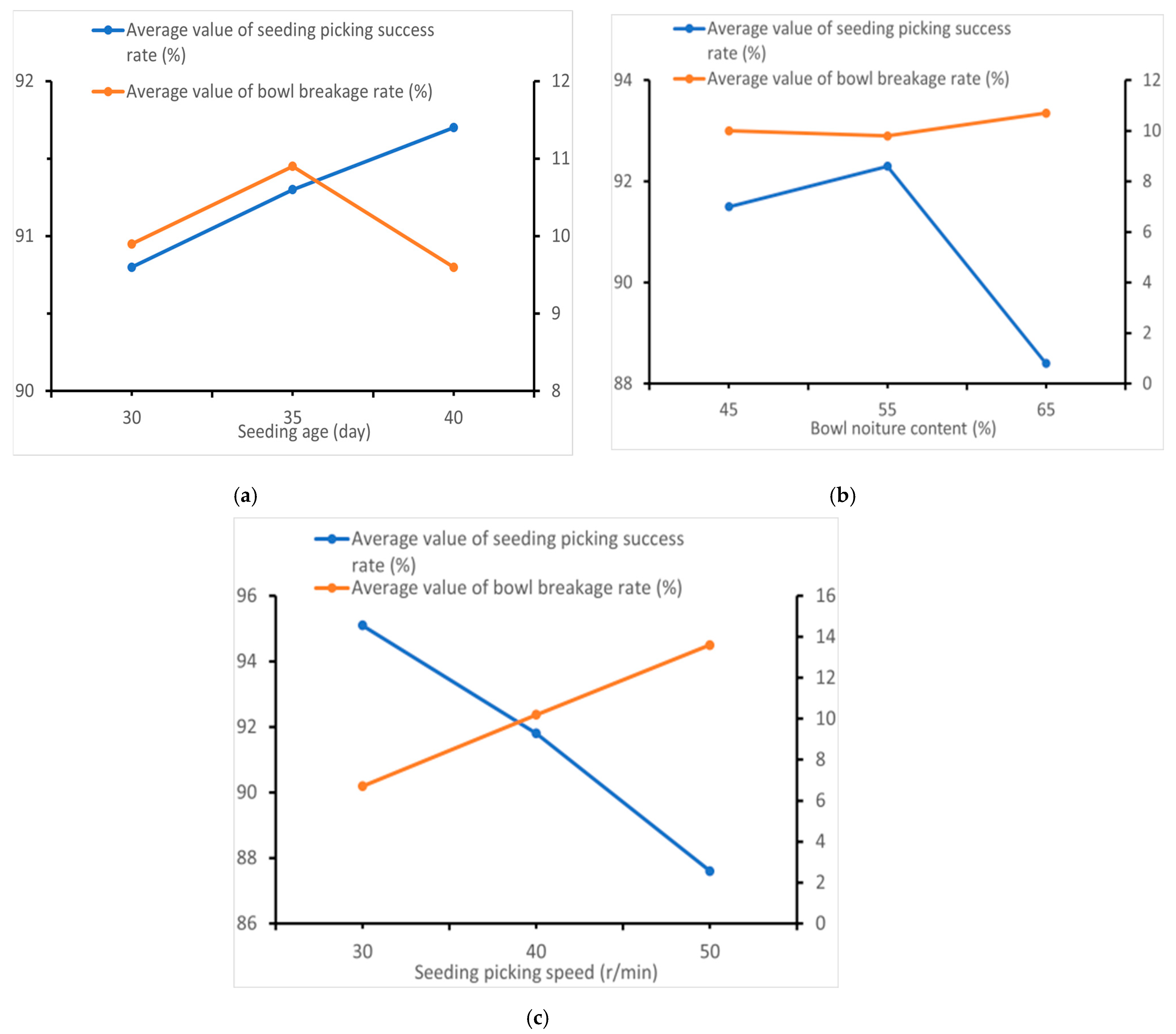
As shown by the test results, the average success rate of seedling extraction under different combinations of test levels is 96.88%; the success rate of seedling extraction is above 90%; the average rate of potting body breakage is 3.19%; and the average rate of breakage is below 20%. It is found that most of the potting body breakage is concentrated at the edges of the insertion hole of the seedling claws as well as at the potting body roots, which is mainly because the underdeveloped root system of some potting seedlings leads to a poor entanglement degree of the potting body substrate. The main reason is that the root system of some potting seedlings is not developed, resulting in the poor degree of entanglement in the potting matrix. The average values for the success rate of seedling extraction and the potting breakage rate under different levels of test factors are shown in Figure 17.
The orthogonal test results for chilli seedlings are shown in Table 4. The results shown in Table 5 were obtained by selecting 64 tomatoes and chillies with water content of around 55% and age of 40 days, respectively, at a picking speed of 30 r/min. The test results showed that with the optimal combination of parameters, the tomato and broccoli seedling extraction success rate was 93.75% and 96.88%, respectively, and the potting breakage rate was 3.48% and 6.01%, respectively. The success rate of seedling extraction was more than 90% and the potting breakage rate was less than 20%. These test results are good, meet a variety of seedling extraction requirements, and the system effectively reduces the potting breakage rate.

4. Discussion

This paper addresses issues found when using existing automatic vegetable transplanters, such as low seedling-picking efficiency, high seedling-pot damage rate, and poor stability of the seedling-picking and -placing mechanism. A whole-row mechanical two-jaw automatic vegetable seedling-picking and -dropping mechanism has been designed. A “reciprocating common rail”-type seedling-picking trajectory is proposed, and a full-row mechanical two-claw seedling-picking mechanism consisting of a planetary gear-linkage mechanism and a clamping mechanism has been designed. The coordination method between seedling feeding and picking has been determined, and parameters for the supporting seedling-feeding mechanism have been designed, completing key parameter design and modelling. Through single-factor simulation experiments, the optimal combination of key parameter levels for the seedling-picking claws has been selected. A three-factor three-level orthogonal experiment was conducted to determine the optimal working parameter combination, and seedling-picking performance tests were carried out on pepper, tomato, and cauliflower seedlings. The test results meet relevant national standards, indicating that the seedling-picking and -placing mechanism has strong stability and good versatility, meets the design requirements and provides a solid foundation for the design of seedling-picking mechanisms in automatic transplanters.
Based on the study of the physical characteristics of three types of vegetable seedlings, combined with theoretical analysis and comprehensive consideration of plug-tray characteristics, the length of the seedling-picking claw is determined to be 180 mm, the width 6 mm, and the thickness 1.5 mm, with a 2 mm distance from the plug wall during insertion and an insertion depth of 35 mm. Bench performance tests and analysis of the seedling-picking and -placing mechanism were conducted using pepper, tomato, and cauliflower seedlings as test objects, with picking speed, pot moisture content, and seedling age as experimental factors in a three-factor three-level orthogonal test. The results show that the optimal seedling-picking effect is achieved at a picking speed of 30 r/min, moisture content of 55%, and seedling age of 40 days. Under these conditions, the success rates for pepper, tomato, and cauliflower seedling picking are 96.88%, 93.75%, and 96.88%, respectively, with pot breakage rates of 6.01%, 3.48%, and 3.19%, respectively. Compared with traditional methods, the success rate improves by 2%, and the damage rate reduces by 3%.
However, some issues have not been fully considered, such as the lack of field trials to verify the impact of vibration on seedling picking, and the absence of virtual prototype simulation tests, which prevents a comparison between theory, simulation, and practice, hence lacking scientific rigor. Additionally, no comparative tests were conducted with traditional three-claw or four-claw models. Although key structural parameters were derived through theoretical analysis, models were drawn, and bench tests verified the accuracy and reliability of the models, future research will further improve aspects including production costs and maintenance difficulty.
In summary, the whole-row mechanical two-jaw automatic vegetable seedling-picking and -dropping mechanism presented in this paper and the proposed “reciprocating common rail”-type seedling-picking trajectory have, to some extent, improved the success rate of traditional seedling-picking mechanisms and reduced the damage rate to pot seedlings, laying a solid foundation for the design of seedling-picking mechanisms in automatic transplanters.

5. Conclusions

(1)
In response to the problems of low seedling-picking efficiency, high pot injury rate, and poor stability in the seedling-picking and -planting mechanisms of automated transplanting technology, we designed a full-row mechanical two-claw automatic seedling-picking and -planting mechanism and proposed a “reciprocating common rail”-type seedling-picking and -planting trajectory.
(2)
Through the study of the physical characteristics of different vegetable seedlings and combined with the use of the 128-cell seedling tray, theoretical analysis was conducted on the seedling-picking and -planting trajectory and the structural parameters of the key component, the seedling-picking claw. The specific parameters obtained are as follows: crank OE length l1 = 34 mm, connecting rod EF length l = 34 mm, slide rod DF length l3 = 70 mm, arc chute radius of the trajectory groove l4 = 45 mm, seedling-picking-claw length 180 mm, width 6 mm, thickness 1.5 mm, insertion distance from the cell wall 2 mm, and insertion depth 35 mm.
(3)
Based on the specific structural parameters of the key components, a bench test platform for seedling picking and planting was built, and experimental verification was conducted with different vegetable seedlings. The results show that the actual motion trajectory of seedling picking and planting is basically the same as the ideal seedling-picking trajectory. When the picking speed was 30 r/min, moisture content was 55%, and seedling age was 40 days, the success rate of chilli seedling picking was 96.88% with a pot breakage rate of 6.01%; the success rate of tomato seedling picking was 93.75% with a pot breakage rate of 3.48%; and the success rate of broccoli seedling picking was 96.88% with a pot breakage rate of 3.19%. Compared with traditional methods, the success rate improves by 2%, and the damage rate reduces by 3%, meeting national standards and relevant requirements. This establishes a theoretical foundation for automated vegetable seedling-picking and -planting technology.

Author Contributions

Conceptualization, J.H., X.L., Y.X. and M.Z.; methodology, J.H., Y.Z. (Ying Zang), Z.W., J.L., W.Y. (Wenwu Yang), Y.X., Y.Z. (Yue Zhang) and W.Y. (Weijie Yan); software, J.H., Y.X., Y.Z. (Yue Zhang) and W.Y. (Weijie Yan); validation, J.H., Y.Z. (Yue Zhang) and W.Y. (Weijie Yan); formal analysis, J.H. and Y.X.; investigation, J.H., Y.Z. (Yue Zhang), W.Y. (Weijie Yan) and Y.X.; resources, J.H., Y.Z. (Yue Zhang), Y.X. and W.Y. (Weijie Yan); data curation, J.H. and Y.Z. (Yue Zhang); writing—original draft preparation, J.H.; writing—review and editing, X.L. and J.H.; visualization, J.H., Y.X., Y.Z. (Yue Zhang) and W.Y. (Weijie Yan); supervision, M.Z., X.L. and Z.W.; project administration, X.L.; and funding acquisition, M.Z. and Z.W. All authors have read and agreed to the published version of the manuscript.

Funding

This research was funded by Guangdong Provincial Basic and Applied Basic Research Fund Project (Grant No. 2024A1515010463).

Data Availability Statement

The data that supports this study will be shared upon reasonable request to the corresponding author.

Acknowledgments

We would like to express our gratitude to the partners of the field soil tank teaching base of South China Agricultural University for their help and support in field management and machinery maintenance.

Conflicts of Interest

The authors declare no conflicts of interest.

References

  1. Sharma, A.; Khar, S. Design and development of a vegetable plug seedling transplanting mechanism for a semi-automatic transplanter. Sci. Hortic. 2024, 326, 112773. [Google Scholar] [CrossRef]
  2. Wang, Y.W.; He, Z.L.; Wang, J.; Wu, C.; Yu, G.; Tang, Y. Experiment on transplanting performance of automatic vegetable pot seedling transplanter for dry land. Editor. Off. Trans. Chin. Soc. Agric. Eng. 2018, 34, 19–25. [Google Scholar] [CrossRef]
  3. Zhao, S.Y.; Lei, X.J.; Liu, J.Z.; Jin, Y.; Bai, Z.; Yi, Z.; Liu, J. Transient multi-indicator detection for seedling sorting in high-speed transplanting based on a lightweight model. Comput. Electron. Agric. 2023, 211, 107996. [Google Scholar] [CrossRef]
  4. Dang, Y.G.; Jin, X.; Li, H.; Wang, J.; Lu, Y.; Ding, B.; Li, X. Design of single-degree-of-freedom four-bar seedling-taking and throwing manipulator. J. Agric. Eng. 2019, 35, 39–47. [Google Scholar] [CrossRef]
  5. Wang, Y.W.; Tang, Y.H.; Wang, J.; Cheng, S. Parameter Optimization for Dibble-type Planting Apparatus of Vegetable Pot Seedling Transplanter in High-speed Condition. J. Agric. Mach. 2016, 47, 91–100. [Google Scholar] [CrossRef]
  6. Chen, Y.S.; Liu, X.C. Development report of China vegetable mechanization in 2019. J. Chin. Agric. Mech. 2020, 41, 46–53. [Google Scholar] [CrossRef]
  7. Shi, J.W.; Hu, J.P.; Liu, W.; Lv, J.; Jin, Y.; Yao, M.; Wang, C. The Design and Experiment of a Motion Control System for the Whole-Row Reciprocating Seedling Picking Mechanism of an Automatic Transplanter. Agriculture 2025, 15, 1423. [Google Scholar] [CrossRef]
  8. Singh, N.K.; Narang, M.K.; Thakur, S.S.; Singh, M.; Singh, S.K.; Prakash, A. Influence of transplanting techniques and age of wash root type seedlings on planting attributes of paddy rice. Cogent Food Agric. 2023, 9, 2176978. [Google Scholar] [CrossRef]
  9. Han, C.J.; Xiao, L.Q.; Xu, Y.; Zhang, J.; Li, H. Design and experiment of the automatic transplanter for chili plug seedlings. Trans. Chin. Soc. Agric. Eng. (Trans. CSAE) 2021, 37, 20–29. [Google Scholar] [CrossRef]
  10. Yang, T. Research on Key Components and Mechanism of Trailer-Mounted Automatic Pick-and-Place Seedling Transplanting Machine. Master’s Thesis, Kunming University of Science and Technology, Kunming, China, 2022. [Google Scholar]
  11. Zhang, L.H.; Qiu, L.C.; Tian, S.B. Progress in the research of manipulator of transplanting potted tray seedlings. Agric. Sci. Technol. Equip. 2009, 10, 28–31. [Google Scholar] [CrossRef]
  12. Wang, J.; Li, H.; Ma, Z.W.; Hao, J.; Liu, W. Analysis and countermeasures of mechanization development of domestic and foreign facility vegetables. J. Chin. Agric. Mech. 2023, 44, 124. [Google Scholar] [CrossRef]
  13. Yu, G.H.; Wang, L.; Sun, L.; Zhao, X.; Ye, B. Advancement of mechanized transplanting technology and equipments for field crops. Trans. Chin. Soc. Agric. Mach. 2022, 53, 1–20. [Google Scholar] [CrossRef]
  14. Ryu, K.H.; Kim, G.; Han, J.S. Ae-automation and emerging technologies. J. Agric. Eng. Res. 2001, 78, 141–146. [Google Scholar] [CrossRef]
  15. He, Y.K.; Yan, H.; Cui, W.; Chen, K.; Han, Z.; Bao, C. Research Situation and Analysis on Automatic Transplanting Technology for Vegetable Seedling. Agric. Eng. 2018, 8, 1–7. [Google Scholar] [CrossRef]
  16. Chen, X.J.; Lü, Z.J.; Xue, X.L.; Xin, L.; Yu, Q.; Yu, Y.; Zhao, Y. Development and performance experiment of wireless remote control walking rice transplanter. Editor. Off. Trans. Chin. Soc. Agric. Eng. 2017, 33, 10–17. [Google Scholar] [CrossRef]
  17. Khadatkar, A.; Mathur, S.M. Design and development of an automatic vegetable transplanter using a novel rotating finger device with push-type mechanism for plug seedlings. Int. J. Veg. Sci. 2022, 28, 121–131. [Google Scholar] [CrossRef]
  18. Sun, X.X.; Liu, Y.; Li, B.; Niu, G.L.; Wang, T.; Dong, Y.C. Research Status and Prospect of Seedling Pick-up Device for Automatic Plug Seedling Transplanter. J. Chin. Agric. Mech. 2021, 42, 22–28. [Google Scholar] [CrossRef]
  19. Zhou, Y.; Sun, L. Analysis on Development Status of Vegetable Plug Seedling Transplanter. South. Agric. Mach. 2016, 47, 16–19. [Google Scholar] [CrossRef]
  20. Lawrence, M.J.; Buckmaster, D.R.; Lamont, W.J. A pneumatic dibbling machine for plastic mulch. Appl. Eng. Agric. 2007, 23, 419–424. [Google Scholar] [CrossRef]
  21. Xia, G.B.; Han, C.J.; Guo, H.; Zhang, J.; Ge, P.; Xu, Y. Research Status and Development Trends of Key Components of Fully Automatic Transplanting Machinery. J. Agric. Mech. Res. 2019, 41, 1–7. [Google Scholar] [CrossRef]
  22. Yang, L.H. Design and Research on Control System of Full-automatic Vegetable Pot Seedling Transplanter. Master’s Thesis, Jiangsu University, Zhenjiang, China, 2017. [Google Scholar]
  23. He, Y. Design and Research on High-Speed Automatic Seedling Pick-up System for Vegetable Plug Seedling Transplanting. Ph.D. Thesis, Chinese Academy of Agricultural Mechanization Sciences, Beijing, China, 2018. [Google Scholar]
  24. Yu, Y.; Liu, J.; Ye, B.; Yu, G.; Jin, X.; Sun, L.; Tong, J. Design and experimental research on seedling pick-up mechanism of planetary gear train with combined non-circulargear transmission. Chin. J. Mech. Eng. 2019, 32, 49. [Google Scholar] [CrossRef]
  25. Ye, B.L.; Yi, W.M.; Yu, G.H.; Yang, G.; Zhao, X. Optimization design and test of rice plug seedling transplanting mechanism of planetary gear train with incomplete eccentric circular gear and non-circular gears. Int. J. Agric. Biol. Eng. 2017, 10, 43–55. [Google Scholar] [CrossRef]
  26. Tong, Z.; Yu, G.; Zhao, X.; Liu, P.; Ye, B. Design of vegetable pot seedling pick-up mechanism with planetary gear train. Chin. J. Mech. Eng. 2020, 33, 95–105. [Google Scholar] [CrossRef]
  27. Yu, G.H.; Chen, Z.W.; Ye, B.L.; Zhao, Y.; Zhu, J. Study on a New Non-uniform and Intermittent Mechanism. China Mech. Eng. 2012, 23, 2778–2782. [Google Scholar] [CrossRef]
  28. Yu, G.H.; Yu, T.F.; Ye, B.L.; Hu, H.J.; Wang, L.W. Design of a rotary hole tray seedling pick-up mechanism. J. Mech. Eng. 2015, 51, 67–76. [Google Scholar] [CrossRef]
  29. Yin, D.Q.; Wang, J.Z.; Zhou, M.L.; Yang, Y.; Wang, J. Optimal design and experiment of vegetable potted seedlings pick-up mechanism for exploring and picking-pushing plugs. Nongye Jixie Xuebao/Trans. Chin. Soc. Agric. Mach. 2019, 50, 64–71. [Google Scholar] [CrossRef]
  30. Hu, J.P.; Liu, Y.T.; Liu, W.; Zhang, S.; Han, L.; Zeng, T. Experiment on Combined Seedling Picking Device with Top Clamping and Pulling. Trans. Chin. Soc. Agric. Mach. 2022, 53, 10–117. [Google Scholar] [CrossRef]
  31. Zhou, H.L.; Liu, K.; Tong, J.H.; Li, Z.; Rao, Y. Design and Test of Row Picking End-effectors for Potted Seedlings in Greenhouses. Trans. Chin. Soc. Agric. Mach. 2023, 54, 82–90. [Google Scholar] [CrossRef]
  32. Zhang, K.B. Design and Experiment on Key Components of Full-Automatic Plug Type Chili Transplanter. Master’s Thesis, Shandong Agricultural University, Tai’an, China, 2024. [Google Scholar]
  33. Shentu, L.F.; Wu, X.; Sun, X.Z.; Zhang, W. Design of sweet potato planting mechanism based on genetic algorithm. Chin. Agri. Mech. 2019, 40, 6–11. [Google Scholar] [CrossRef]
  34. JB/T10291-2013; Cable Trays for Electrical Control and Distribution. Ministry of Industry and Information Technology: Beijing, China, 2013.
  35. Shen, D.S. Design and Experiment of Seedling Pick-up End-Effector Based on Mechanical Properties of Cabbage Pot Seedlings. Master’s Thesis, Northeast Agricultural University, Harbin, China, 2019. [Google Scholar]
Figure 1. Schematic diagram of potting measurement parameters.
Agriculture 16 00562 g001
Figure 2. Potting compression test.
Agriculture 16 00562 g002
Figure 3. Tensile strength test.
Agriculture 16 00562 g003
Figure 4. Seedling extraction performance test.
Agriculture 16 00562 g004
Figure 5. Distribution of physical parameters of different potting seedlings.
Agriculture 16 00562 g005aAgriculture 16 00562 g005b
Figure 6. Compression force–displacement relationship diagram.
Agriculture 16 00562 g006
Figure 7. Results of potting force test.
Agriculture 16 00562 g007
Figure 8. Schematic diagram of the structure of the seedling pick-up and drop-off mechanism. 1. Mounting base 2. Planetary wheel system-linkage mechanism 3. Track slot 4. End-effector mounting plate. 5. Clamping mechanism 6. Drive plate 7. Sprockets.
Agriculture 16 00562 g008
Figure 9. Planetary wheel train-linkage mechanism structure sketch. 1. Track groove 2. Slide pin 3. Intermediate wheel 4. Planetary carrier 5. Planetary wheel 6. Connecting rod 7. Seedling supply mechanism 8. Seedling tray 9. Potting seedling 10. End-effector 11. Slide pin shaft 12. Slide bar 13. Sun wheel.
Agriculture 16 00562 g009
Figure 10. Principle of trajectory formation.
Agriculture 16 00562 g010
Figure 11. Simplified diagram of planetary wheel system-linkage mechanism.
Agriculture 16 00562 g011
Figure 12. Genetic algorithm operation flow.
Agriculture 16 00562 g012
Figure 13. Schematic diagram of the structure of the clamping mechanism. 1. End-effector mounting plate 2. Connecting plate 3. Tensioning lever 4. Spring 5. Limit block 6. Seedling taking claw 7. Fixed plate 8. Rotating shaft 9. Square block 10. Seedling clamping cam 11. Pulling plate 12. Cam spindle.
Agriculture 16 00562 g013
Figure 14. Two-jaw end-effector.
Agriculture 16 00562 g014
Figure 15. Force analysis of potting seedling pick-up.
Agriculture 16 00562 g015
Figure 16. Schematic diagram of the key parameters of the seedling extraction claw.
Agriculture 16 00562 g016
Figure 17. Effect of different factor levels on the test indicators. (a) Effect of seedling age on seedling-picking success rate and damage rate, (b) effect of plug moisture content on seedling-picking success rate and damage rate, and (c) effect of seedling-picking speed on seedling-picking success rate and damage rate.
Agriculture 16 00562 g017
Table 1. Table of experimental factor levels.
Level (of Achievement etc.) Considerations
Seedling Extraction Speed A/r-min−1Potting Water Content B/%Seedling Age C/d
1304530
2405535
3506540
Table 2. Measurement results recording basic physical characteristics of potting seedlings.
Types of Potting SeedlingsTest IndicatorsPotting Height/mmMaximum Leaf Spread/mmSeedling Stem/mmSeedling Weight/g
minimum value88.960.02.212.2
chilliaverage value103 ± 7.9868.2 ± 5.082.3 ± 0.0614.4 ± 1.93
maximum values120.478.12.519.6
minimum value83.963.92.211.6
tomatoaverage value106.2 ± 9.0989.5 ± 10.82.9 ± 0.2715.5 ± 2.33
maximum values129.3114.33.321.6
Minimum value83.562.82.012.0
broccoliaverage value105.4 ± 10.9189.7 ± 14.32.4 ± 0.1915.0 ± 1.97
Maximum value131.3112.92.822.5
Table 3. Illustrative table of parameters relevant to kinematic analysis.
SignHidden MeaningCharacteristicSignHidden MeaningCharacteristic
l 1 Crank OE length (mm)constant β 1 Crank OE angle (°)Variable
l 2 Connecting rod EF length (mm)constant β 2 Connecting rod EF angle of rotation (°)Variable
l 3 Slide bar DF length (mm)Constant β 3 Slide bar DF angle of rotation (°)Variable
l 4 Radius of circular arc chute (mm)Constant β 4 Angle between extension line and slide bar DF (°)Variable
l 5 Distance between end of take-up and centre of articulation (mm)Constant δ Slot inclination (°)Constant
x D Horizontal coordinates of point DVariable y D Vertical coordinate of point DVariable
x E Horizontal coordinates of point EVariable y E Vertical coordinate of point EVariable
x F Horizontal coordinates of point FVariable y F Vertical coordinate of point FVariable
x G Horizontal coordinates of point GConstant y G Vertical coordinate of point GConstant
ω Crank OE speedConstant
Table 4. Orthogonal Test Results for Chilli Seedlings.
NumberExperimental FactorsY1Y2
A/r·min−1B/%C/d
111196.096.37
212396.866.01
313292.198.21
421392.979.22
522293.7510.52
623188.2810.86
731288.2814.19
832189.0613.16
933385.1613.14
Y1k195.0592.4591.14
k291.6793.2291.66
k387.588.5491.41
R7.554.680.52
Y2k16.869.9310.13
k210.29.9010.97
k313.5010.749.46
R6.630.841.52
Table 5. Results of different potting seedling take-up performance tests.
Types of Potting SeedlingsNumber of Successful Seedling Collection/PlantSuccess Rate of Seedling Collection/%Crushing Mass/gMantle Crushing Rate/%
tomato6093.7542.313.48
chilli6296.8873.076.01
Disclaimer/Publisher’s Note: The statements, opinions and data contained in all publications are solely those of the individual author(s) and contributor(s) and not of MDPI and/or the editor(s). MDPI and/or the editor(s) disclaim responsibility for any injury to people or property resulting from any ideas, methods, instructions or products referred to in the content.