Article

A Study on the Interaction Mechanism Between Disc Coulters and Maize Root-Soil Composites Based on DEM-MBD Coupling Simulation


1
College of Intelligent Mechatronics Engineering, Zhongyuan University of Technology, Zhengzhou 450007, China
2
College of Mechanical and Electronic Engineering, Tarim University, Alar 843300, China
3
College of Mechanical and Electronic Engineering, Henan Agriculture University, Zhengzhou 450002, China
4
Key Laboratory of Bionic Engineering, Ministry of Education, Jilin University, Changchun 130022, China
5
College of Biological and Agricultural Engineering, Jilin University, Changchun 130022, China
*
Authors to whom correspondence should be addressed.
Agriculture 2026, 16(2), 270; https://doi.org/10.3390/agriculture16020270
Submission received: 16 December 2025 / Revised: 16 January 2026 / Accepted: 18 January 2026 / Published: 21 January 2026

Abstract

To solve the problems of high resistance and blockage in stubble-breaking operations, it is necessary to reveal the interaction mechanism between disc coulters and crop root–soil composites. This study developed a discrete element method–multi-body dynamics (DEM-MBD) coupling model of the stubble-breaking operation and verified the accuracy of the model through soil bin tests (error < 20%) and field experiments (error < 32%). The model was used to investigate the effects of different design parameters (coulter type and disc radius) and operating parameters (tillage speed and depth) on the stubble-breaking operation. The results showed that due to the significant strengthening effect of roots on soil, the resistance of disc coulter stubble-breaking operation was high; the number of roots in contact with the blade edge and the amount of root deformation significantly affected the resistance of the disc coulter; irreversible deformation of roots and soil could easily lead to the holes and root hairpin effects in the seeding furrow; compared to plain disc coulters, the difference in the time of deformation and fracture of the roots made the resistance of the notched coulter lower. The wavy disc coulter with a longer edge curve made its resistance higher; the disc coulter with a greater radius, higher tillage speed, and deeper tillage depth significantly increased the tillage resistance. However, the disc coulter with a greater radius or a higher tillage speed was beneficial for improving stubble-breaking performance. This study revealed the interaction mechanism between disc coulters and maize root-soil composites, providing a theoretical basis for the optimization design of no-till stubble-breaking devices.

1. Introduction

No-till technology can effectively protect soil fertility and prevent soil degradation due to wind and water erosion; therefore, it is widely promoted and popularized [1,2,3]. However, due to the large amount of straw and stubble left in the farmland, no-till planters usually encounter problems such as severe blockages and high resistance, which have become one of the main bottlenecks in promoting no-till technology. The stubble is a kind of typical root–soil composite, which has a stable structure formed by the interaction between roots and soil [4,5,6]. The crop root–soil composite not only causes serious blockage of tillage equipment, high resistance, and energy consumption, but also affects the structure of the seedbed and seed germination [7,8]. Therefore, it is necessary to design a stubble-breaking device that can efficiently break stubble.
The disc stubble-breaking device is a commonly used stubble-breaking component. The most important tillage component of this stubble-breaking device is the disc coulter, which is suitable for breaking thick stubble and stems. It has excellent anti-clogging performance and is widely used in no-till seeders [7,8]. To improve the operational performance of the disc stubble-breaking device, Torotwa et al. [9] developed a biomimetic disc with a morphology similar to mole claws to optimize the disc coulter under dense cover conditions, while minimizing soil disturbance; Zeng et al. [10] compared the operational performance of disc coulters with different numbers of teeth and found that the tillage performance of disc coulters was influenced by the type of coulter. The tooth coulter left less residue and caused greater soil disturbance. The eight-tooth coulter showed the most positive performance in disturbing residues and soil; Kogut, Karayel, Malasli M.Z., and Zhang et al. [11,12,13,14] found that the operating and structural parameters of the disc coulter had a significant impact on resistance, operating performance, and tillage depth. Additionally, some studies typically developed empirical models based on data obtained from specific agricultural environments and optimized the design parameters, operational parameters, and other aspects of stubble-breaking devices. Although these studies designed high-performance stubble-breaking devices, they did not reveal the interaction mechanism between stubble-breaking coulters and crop root–soil composites. Therefore, current research and design standards could not provide a theoretical basis for the design of stubble-breaking devices.
In the field of soil and water conservation, mature and systematic theories could provide inspiration for revealing the interaction mechanism between stubble-breaking components and crop root–soil composites. Researchers used experimental, mathematical–analytical, and simulation methods to investigate the impact of roots on soil reinforcement [5,15,16,17,18]. These studies showed that roots had a significant mechanical reinforcement effect on the soil. The deeper vertical main roots served as anchor rods, anchoring the surface soil to a more stable lower layer of bedrock. The widely distributed root network spanned across the shear plane. When the soil underwent shear deformation, these roots were stretched, and the shear stress was converted into the tensile force of the roots through the interface force between the root and soil, effectively improving the apparent shear strength of the root–soil composite. In the field of agricultural engineering, scholars have also attempted to use various methods to solve the interaction mechanism between disc coulters and crop root–soil composites. Bai et al. [19] developed a dynamic model to analyze the interaction between tillage equipment and maize stubble. This research showed that factors such as the radius and structure of the disc coulter, stubble size, and cutting speed have a significant impact on stubble-breaking resistance; Liu et al. [20] developed a mathematical-analytical model for the interaction between disc coulters and maize root–soil composites. This research showed that the force on a flat blade for cutting stubble was related to the mechanical properties of roots, soil, and root–soil interfaces. The deformation of roots and soil had a significant impact on the stress and operational efficiency of tillage components. Using experimental methods, Zhao, Zheng et al. [21,22] conducted cutting experiments on maize and rice root–soil composites using a flat blade. The study showed that the operating parameters of the flat blade and the mechanics of roots and soil had a significant impact on the interaction. In recent years, with the rapid development of computer technology and numerical methods, numerical methods have been widely used to study the interaction between tillage components and root–soil composites. Yuan et al. [23] used the finite element method (FEM) to develop a FEM model of maize root–soil composite; Zhang et al. [11,24] used the DEM to develop a DEM model of maize root–soil composite, and based on this model, designed and optimized the optimal combination of operating parameters for the disc coulter; Tamas et al. [25] developed an accurate model of a root–soil composite and explored the interaction law between sweeping bodies and root–soil composites. The study showed that soil solidity and the number of roots per unit volume had a significant impact on the resistance of sweeping operations; Zou et al. [26] developed a spinach root–soil composite model and investigated the effects of operating parameters of a vibrating shovel on the movement patterns of roots and soil particles, as well as the degree of root–soil separation. Obviously, numerical methods were helpful in simulating different work scenarios and evaluating the performance of tillage equipment. These studies only simulated and evaluated macroscopic parameters such as tillage resistance and soil disturbance and did not investigate the interaction process between stubble-breaking components and crop root–soil composites during stubble-breaking operations. According to the theories proposed in the field of soil and water conservation, investigating the quantitative relationship between factors such as resistance of the tillage component, deformation and fracture of roots, and debonding of the root–soil interface, as well as their impact on the operations, could be an effective way to reveal the interaction mechanism.
Based on previous research, this study developed a DEM-MBD coupling model for the interaction between disc coulters and maize root–soil composites. The model was validated through soil bin tests and field experiments. By simulating the stubble-breaking operation of disc coulters, the resistance of disc coulters as well as the deformation of maize roots and soil were given significant attention to reveal the interaction mechanism between the disc coulter and the maize root–soil composite. This study provided a theoretical basis for the design of the stubble-breaking device.

2. DEM-MBD Coupling Simulation of Disc Coulter Stubble-Breaking Operation

2.1. Development of DEM Model for Maize Root–Soil Composite

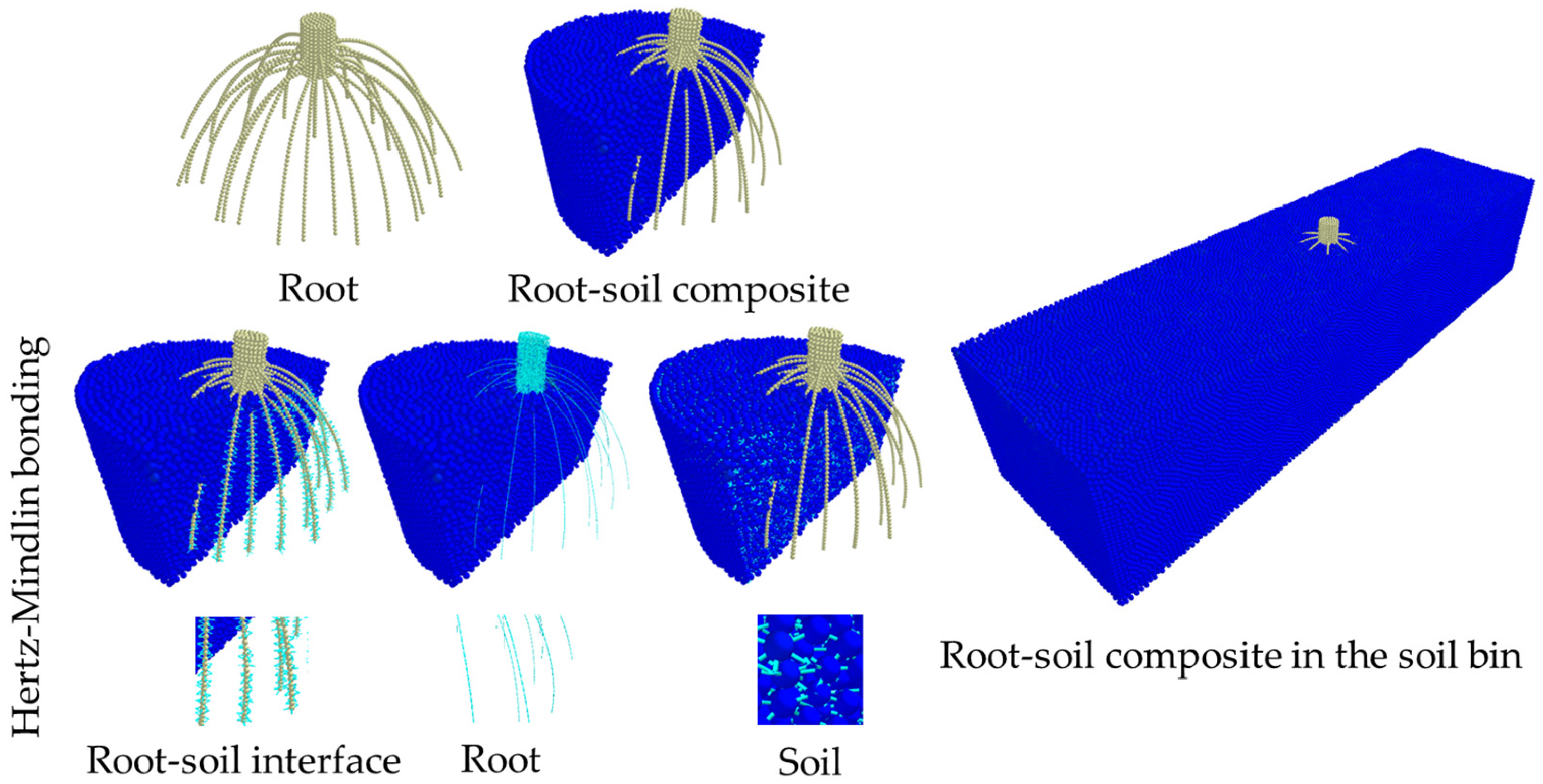
To simulate the stubble-breaking process of a disc stubble-breaking device and investigate the interaction mechanism between disc coulters and crop root–soil composites, an ideal stubble-breaking operation model needed to be developed to eliminate complex and numerous variables to highlight the interaction process. A DEM model of a soil bin with a maize root–soil composite was developed using EDEM 2020 (Altair Engineering, Edinburgh, Midlothian, UK) (Figure 1). This model was developed for maize root–soil composites in Northeast China. The soil in this area was black loam soil, and the maize variety was Zhengdan 958. The above-ground stem diameter of the maize root–soil composite was 35 mm, and average diameter of the root was 3 mm. The DEM model of maize root was created using SolidWorks 2018 (Dassault Systèmes, Suresnes, France) and EDEM 2020. The geometric model of the maize root was developed using SolidWorks 2018 and was imported into EDEM 2020. The application programming interface (EDEM API) was used to compile the specific particle factory plugin, which was then used to fill the cavities inside the maize root model with particles with a radius of 1.5 mm. A soil bin model was developed with dimensions of 1000 mm × 400 mm × 200 mm. According to the research of Liu, Zhang et al. [27,28], developing a soil bin model using randomly generated particles with a radius of 2 mm was accurate and reliable. To accurately describe the adhesion behaviour between each particle, as well as the deformation and failure behaviour of roots and soil during the stubble-breaking process, it is important to use a suitable contact model. Black loam soil has macroscopic high adhesion and agglomeration characteristics, so Hertz-Mindlin with bonding and JKR contact models were most suitable for simulation [28,29]. The Hertz–Mindlin with bonding model could describe the contact force generated by particle motion. Once this contact force exceeded the critical value, it could fracture and would not be repaired. The JKR contact model could accurately describe soil adhesion behaviour. Therefore, a DEM model of maize root–soil composite could be developed based on the two models. Basic physical parameters (Table 1), parameters of Hertz–Mindlin with bonding and the JKR contact model (Table 1), and friction parameters (Table 2) were assigned to the particle of root, soil, and root–soil interface [11,30]. The calculation grid size was set to 5 mm, the Rayleigh time step size to 10−6 s, and the saved data interval to 0.001 s.

2.2. Development of DEM-MBD Coupling Model

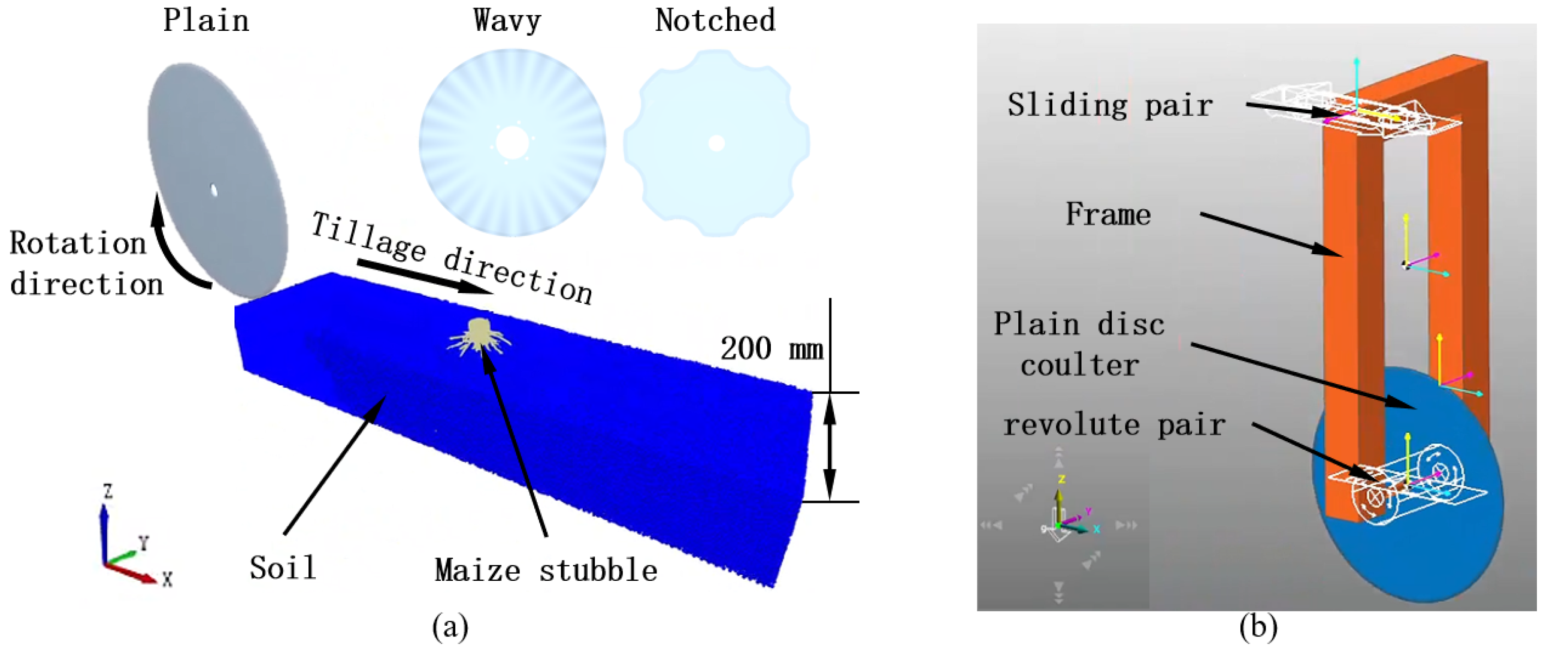
The disc stubble-breaking device was a kind of passive stubble-breaking device, and the disc coulter was a passive coulter that rotated due to the reaction forces of the soil and the stubble acting on the coulter, and the traction force of the tractor. The motion module in EDEM 2020 could not simulate this passive motion, while Recurdyn 2020 (FunctionBay, Inc., Seongnam-si, Republic of Korea) could transmit it to EDEM 2020 through a collaborative simulation interface and module to meet the simulation requirements of the disc coulter. The disc coulter was imported into Recurdyn 2020, and mechanism constraints were added to the model to obtain the MBD model (Figure 2a). Based on the DEM model of maize root–soil composite and the MBD-DEM coupling algorithm, the disc coulter model was imported into EDEM 2020, and data sharing between the two software was achieved through the coupling interface, thus conducting the MBD-DEM coupling simulation (Figure 2b). In contrast, due to the stiffness of 65Mn was much greater than that of maize roots and soil, the deformation of the disc coulter processed from 65Mn could be ignored during stubble-breaking operations. This simplification method was proven by Zhang et al. [11] to have minimal impact on the simulation. The model was validated through the most common disc stubble-breaking operation scenario in the black soil area of Northeast China, where the tillage depth was 80 mm, and the tillage speed was 1 m/s. Considering operational efficiency and simulation accuracy, the fixed time step should be set to 1 × 10⁻⁶ s.

2.3. Simulation Method

Due to the significant impact of different tillage parameters and design parameters on the stubble-breaking operation of disc coulters, the DEM-MBD coupling model was used to investigate the effects of these parameters on the interaction mechanism between disc coulters and maize root–soil composites, as shown in Table 3.
According to the previous research [20], to investigate the influence of various factors on the interaction mechanism, the performance of the disc coulter was evaluated using peak resistance (horizontal peak resistance, vertical peak resistance), average resistance (horizontal average resistance, vertical average resistance) and root dragging distance. The peak resistance was defined as the maximum resistance acted on the disc coulter during the stubble-breaking operation. The average resistance calculation equation was as follows:
F = 1 x 2 x 1 x 1 x 2 F ( x ) d x
F(x)—Instantaneous force at each displacement point x, N;
x1, x2—Start and end points of the displacement interval, mm.
Due to the fact that the average resistance could evaluate the stubble-breaking performance of the disc coulter throughout the entire stubble-breaking process and the measurement values were relatively stable, it was used to verify the accuracy of the model.
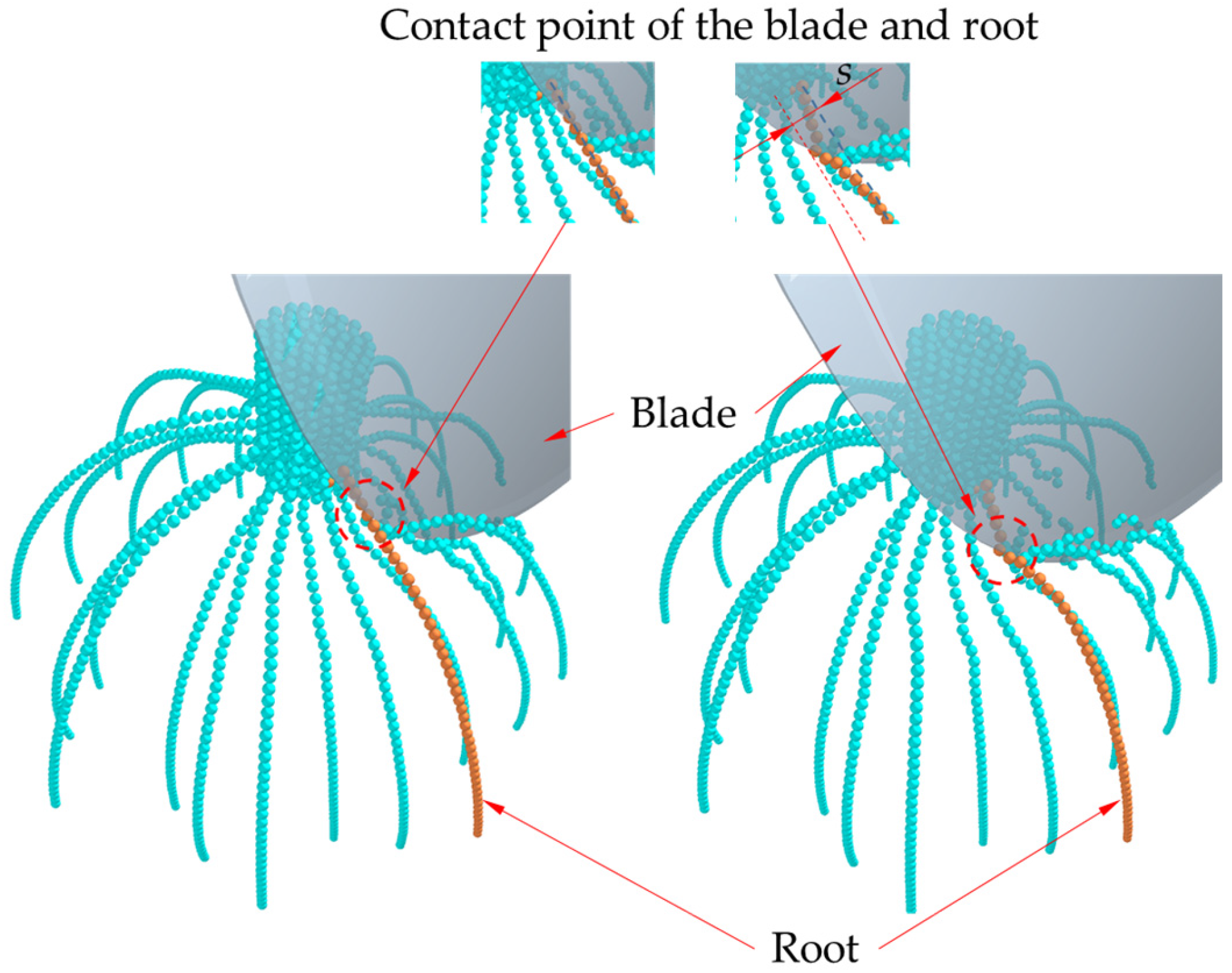
According to previous research [20], the fracture and deformation of the root could significantly affect the resistance of the cutting blade. At the same time, evaluating the deformation and fracture of roots could help evaluate the cutting effect of the disc coulter on maize root–soil composites. Therefore, to evaluate the cutting effect, the dragging distance of the disc coulter on the root was evaluated. A typical cutting case (Figure 3) was selected as the evaluation object, and the morphology of other roots were observed. The root dragging distance was defined as the displacement at the point of contact between the disc coulter and the maize root from the moment the disc coulter came into contact with the maize root until the maize root fractured. As shown in Figure 3, s was the root dragging distance.
The force-displacement curve of the disc coulter used to calculate the peak resistance and the average resistance, as well as the displacement of root particles to calculate the root dragging distance, could be output using EDEM 2020. Based on the research of Zhang et al. [28], the DEM simulation indicated that tillage resistance was highest at 30 mm from maize stalks. To obtain maximum resistance data, the disc coulter was set to operate 30 mm from the stalk axis.

3. Field Experiments

To verify the accuracy of the DEM model and evaluate the actual performance of the disc coulter in the field, it was necessary to conduct soil bin tests and field experiments.

3.1. Materials and Equipment

The field experiment and material collection for the soil bin test were conducted on 28 October 2023, at the Agricultural Experimental Base of Jilin University in Changchun, Jilin Province. The experimental field had been managed under conservation tillage for over five years. The maize variety collected for the soil bin test was Zhengdan 958, and its roots were mainly distributed in the soil layer at a depth of 0–80 mm. The average diameter of the maize stalks was 25 mm. The sample size of the root–soil composite was a cylinder with a diameter of 300 mm and a height of 200 mm. The average root density was 138.20 kg/m3. The wet basis moisture content of the root was 64.78–85.60%. The soil belonged to the black loam soil (46.11% sand, 30.78% silt, and 23.11% clay). The average soil compaction of the tillage layer was 1.12 MPa. The average bulk density of the soil was 2.60 g/cm3, and the average soil moisture content was 20.12%.
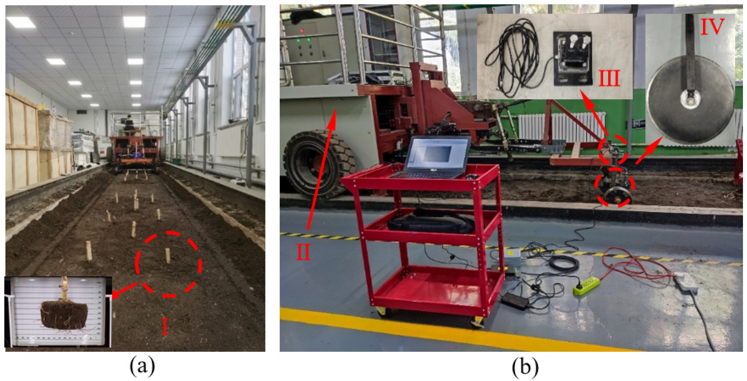
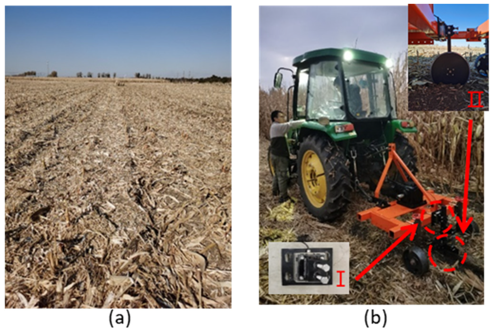
The soil bin test was conducted in the soil bin laboratory (30 m long, 4 m wide) of the College of Biological and Agricultural Engineering at Jilin University (Figure 4a). The soil preparation process was as follows: break up and level the soil—sprinkle water to adjust soil moisture content—compact the soil—bury maize stubble—compact the soil. The soil moisture content in the soil bin was adjusted to 19 ± 0.5%, and soil firmness to 1.2 ± 0.2 MPa. To prevent interference between experimental groups and ensure efficient testing, the soil bin was divided into three sections. The two sides of the sections were set as transition sections, with each transition area measuring 5 m in length. The central section, totaling 6 m in length, was selected as the stable section for recording experimental data. Within the stable section, three rows of maize stubble were arranged along the length of the soil bin, spaced 0.5 m apart. Within each row, three maize stubble points were positioned, also spaced 0.5 m apart (Figure 4a). The primary experimental equipment comprised a soil bin trolley testing system and an experimental platform (Figure 4b). The experimental platform consisted of a frame, two ground wheels, and a three-dimensional force measurement device. The disc coulters were mounted onto the three-dimensional force sensor via a clamping fixture, which was in turn secured to the frame. Before the experiment, a 120 kg counterweight was placed on the frame, and the tillage depth of the disc coulter was adjusted using a ground wheel. During the experiment, the soil bin trolley pulled the experimental platform in a straight-line motion, and a three-dimensional force sensor (Figure 4b) was used to output the horizontal and vertical resistances acting on the disc coulter in real time. It should be noted that the collected maize stubble would be disturbed, which would have a negative impact on the experimental results. However, due to the fact that the disc coulter broke the maize stubble downwards and forwards during the stubble-breaking operation, the influence of deep distributed roots and soil on the operation was not significant, resulting in minimal errors. It was validated by the research of Zhao et al. [31].
Field experiments employed a John Deere 1354 tractor and experimental platform (Figure 5a,b). The experimental platform was connected to the tractor via its three-point hitch. Similarly to the soil bin test, before the experiment, a counterweight was used to apply sufficient downward pressure to the disc coulter to ensure effective breaking residues [32]. The tillage depth of the disc coulters was ensured by adjusting the two ground wheels. During the experiment, a three-dimensional force sensor (Figure 5b) was used to monitor the horizontal and vertical resistances acting on the disc coulters in real time.

3.2. Experimental Methods

To validate the accuracy of the DEM model, verification experiments should be conducted under ideal conditions. Therefore, a soil bin test was employed to validate the DEM model. Zheng, Zhao et al. [21,22] observed that roots were densely distributed within 30 mm of maize stalks, resulting in significant tillage resistance for the disc coulters. To measure the maximum resistance of the disc coulters, the simulation model matched the experimental conditions of the verification experiment. The soil bin test required the disc coulter’s trajectory to run parallel to the straight line connecting the three maize stubble points, maintaining a 30 mm distance from this line. The disc coulter’s tillage depth was set to 80 mm, with the soil bin vehicle operating at a tillage speed of 3.6 km/h.
To verify the accuracy of the model and investigate the interaction mechanism between the disc coulter and the maize root–soil composite, it was necessary to evaluate the tillage effect of the disc coulter. The field experiment was conducted on a 6 m-wide, 50 m-long farm with gentle terrain. The stubble-breaking operation should be carried out on the ridges, with their working trajectory passing through the maize stubble at the centre of the ridge. The tractor’s forward speed was maintained at 3.6 km/h to meet local no-till requirements, with each experimental group repeated three times. This experiment employed a three-dimensional force sensor to measure the horizontal and vertical resistances exerted on the disc coulters. Due to the significant fluctuations in the force-displacement curve measured in soil bin tests and field experiments, and the difficulty in accurately determining the peak resistance due to uncontrollable factors such as soil impurities, the average resistance (horizontal average resistance, vertical average resistance) was used to evaluate the performance of the disc coulter and the accuracy of the model was verified by comparing the average resistance measured in field experiments and a simulation of stubble-breaking operations. The calculation method for average resistance was shown in Equation (1).
Simultaneously, it was necessary to observe the cross-section of the cut stubble to support the simulation results and provide support for the theoretical model of interaction between the disc coulter and maize root–soil composites.

4. Results and Discussion

4.1. Model Validation

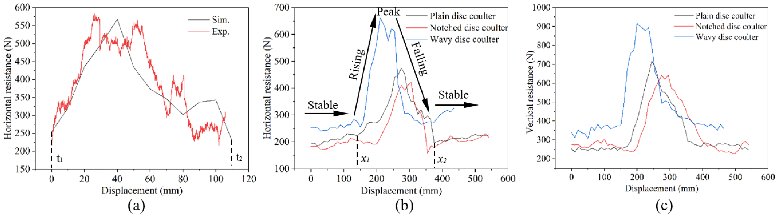
To validate the accuracy of the model, the results of the soil bin test and the field experiments were compared with simulation results. As shown in Figure 6, the trend of the force-displacement curve obtained from measurement and simulation was consistent. The process of breaking the maize stubble started from the point x1 where the curve significantly rose and ended at the inflexion point x2, where the curve significantly dropped to stability. The average resistance could be calculated according to Equation (1). The results of the verification test were shown in Table 4 and Table 5. Compared with the results of the soil bin test, the maximum error of the horizontal and vertical resistances calculated by simulation was less than 20%. Compared with the results of field experiments, the maximum error of the simulation calculation was 32%. As for the field experiment, the difference between simulated data and experimental data could be attributed to the variability of factors such as soil moisture content, rot of the root, structure of the stubble, differences in maize growth, and mechanical properties of the root–soil interface, which affected resistance. The experimental conditions for the soil bin test were relatively ideal with lower errors. However, it could not be denied that there were still differences between simulated data and experimental data due to disturbances in the collected samples. Although there were errors in the simulated data, these errors were within an acceptable range, so the model was accurate and reliable, and could be used to analyze the interaction mechanism between the disc coulter and the maize root–soil composite.

4.2. Analysis of the Process of Stubble-Breaking Operation

Schwarz et al. [18] found that the shear resistance of root–soil composites depended on the deformation of the root. Therefore, to investigate the interaction mechanism between disc coulters and maize root–soil composites, it was essential to investigate the relationship between the root deformation and the resistance of disc coulters during the entire stubble-breaking process.
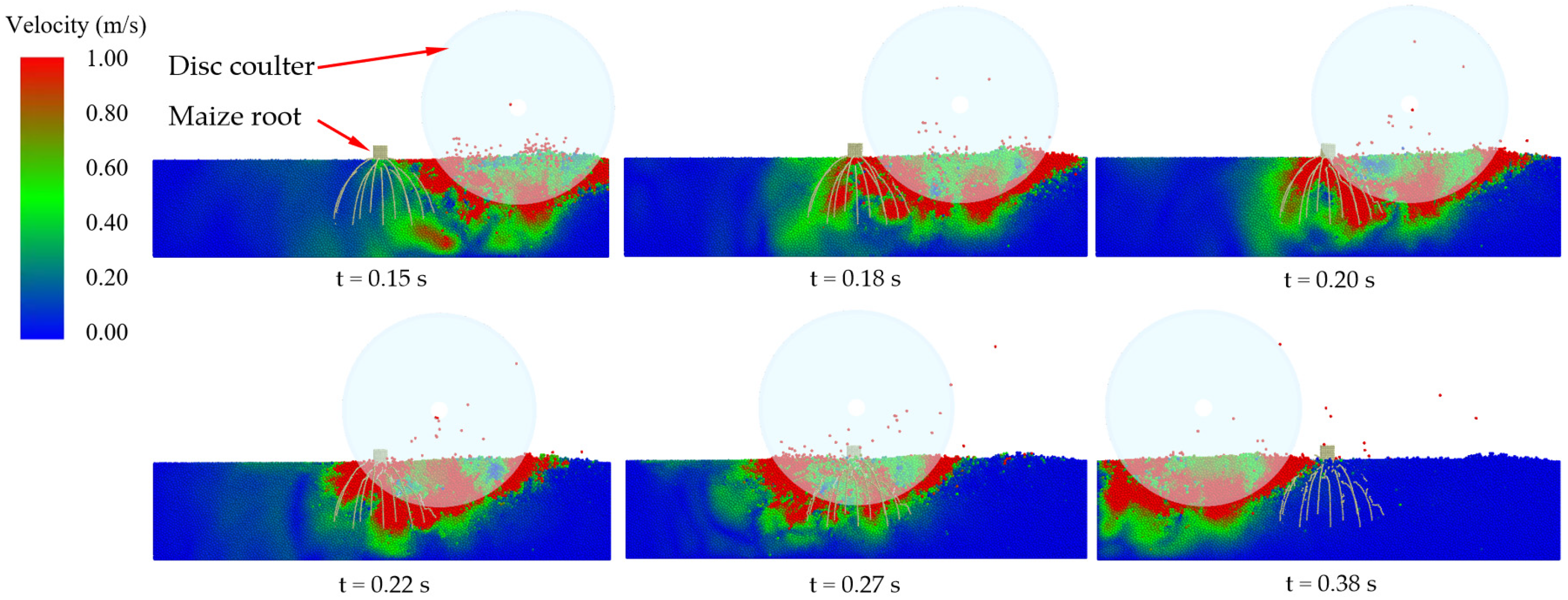
The cutting of a maize root–soil composite using a disc coulter was studied as a case. During the entire stubble-breaking process, the disc coulter sequentially cut through the soil, maize stubble, and soil again. The measured and simulated force-displacement curves for both horizontal and vertical resistances of the disc coulter successively underwent stable, rising, peak, falling, and stable segments (Figure 6). The force-displacement curves in the rising, peak, and falling segments showed significantly higher values, featuring local peaks accompanied by irregular fluctuations. By comparing with the DEM cloud map (Figure 7), it was shown that both horizontal and vertical resistances on the disc coulters significantly increased when breaking the maize stubble. This was consistent with the results obtained by Bai et al. [32] through dynamic analysis and experimental measurements. The above phenomenon also indicated that roots had a significant strengthening effect on soil, and it was precisely because of the presence of roots in the soil that the disc stubble-breaking device needed to face greater resistance. This was consistent with the research of Schwarz, Wu, Liu et al. [4,5,20]. Higher horizontal resistances not only generated greater resistance and energy consumption but also led to significant impact and vibration on tillage equipment, resulting in damage to the machinery; a sudden increase in vertical resistance could lead to problems such as inconsistent tillage depth of the stubble-breaking operation.
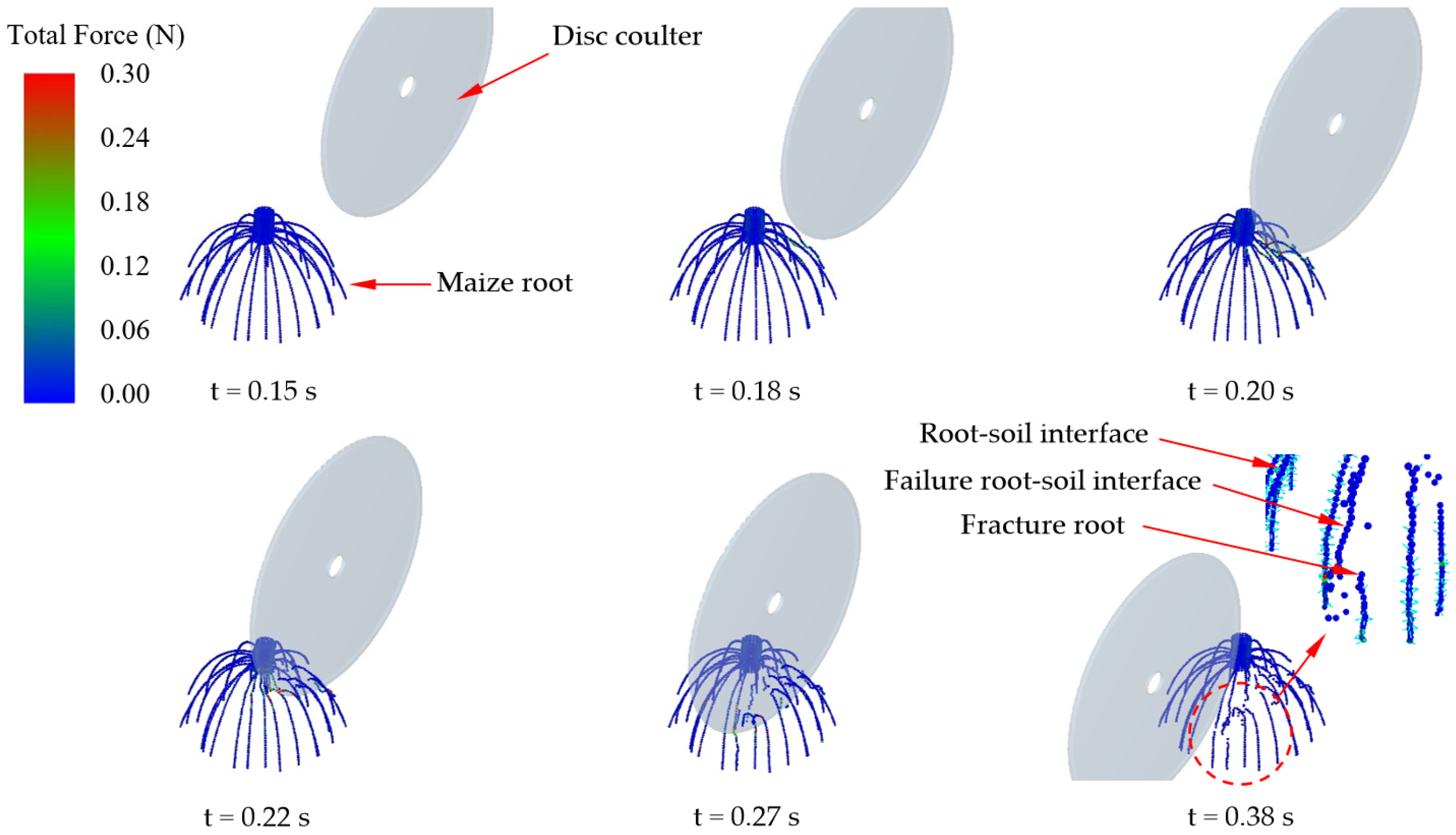
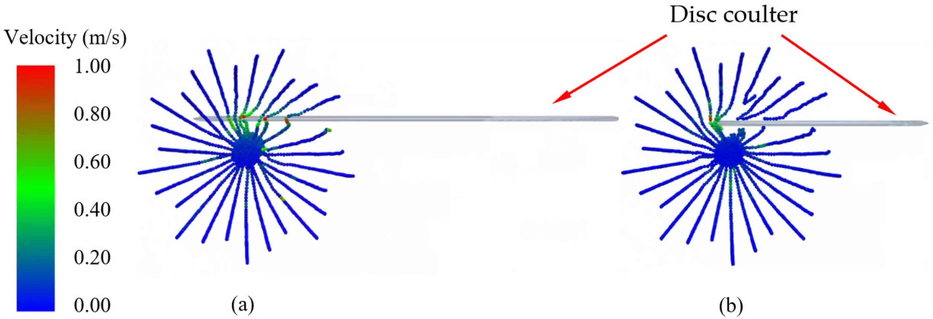
By comparing the force-displacement curve of the simulation with the DEM cloud map of the root, it was found that during the entire stubble-breaking process, when the disc coulter first came into contact with the root, the root was dragged, the local deformation of the root increased with the continuous cutting of the disc coulter (Figure 7), and the horizontal and vertical resistances increased accordingly (Figure 6). As the root dragging distance increased, the roots were subjected to tension (Figure 8), and the resistance of the disc coulter would increase significantly (Figure 6). If the root fractured during the cutting process, the resistance could suddenly decrease (Figure 6). If the roots did not fracture during the stubble-breaking process, they would adhere to the cutting edge of the disc coulter and make it fail (Figure 8). This might be one of the reasons for the blockage. The more roots distributed on the edge of the disc coulter, the greater the horizontal and vertical resistances of the disc coulter. The peak resistance of the disc coulter was related to the number of roots in contact with the edge of the disc coulter and the deformation of each root. Liu et al. [20] also observed this phenomenon, which was called the cumulative effect of root-cutting force. The distribution region of maize roots in the soil was spindle-shaped [33]. During the stubble-breaking process, the contact region between the disc coulter and the densely distributed region of maize roots first increased and then decreased. Correspondingly, the number of roots in contact with the disc coulter also first increased and then decreased. Therefore, the horizontal and vertical resistances of the disc coulter showed a trend of first increasing and then decreasing. This was consistent with the research of Bai et al. [32]. There are differences in root distribution and root fracture time, so the force-displacement curve of the disc coulter would experience irregular fluctuations and abrupt changes. Due to differences in factors such as root structure, distribution characteristics, and decay status, it was difficult to predict resistance using a simple equation. However, by using the above method to analyze the factors that affect the entire stubble-breaking process, it was sufficient to study the interaction between the disc coulter and the maize root–soil composite.
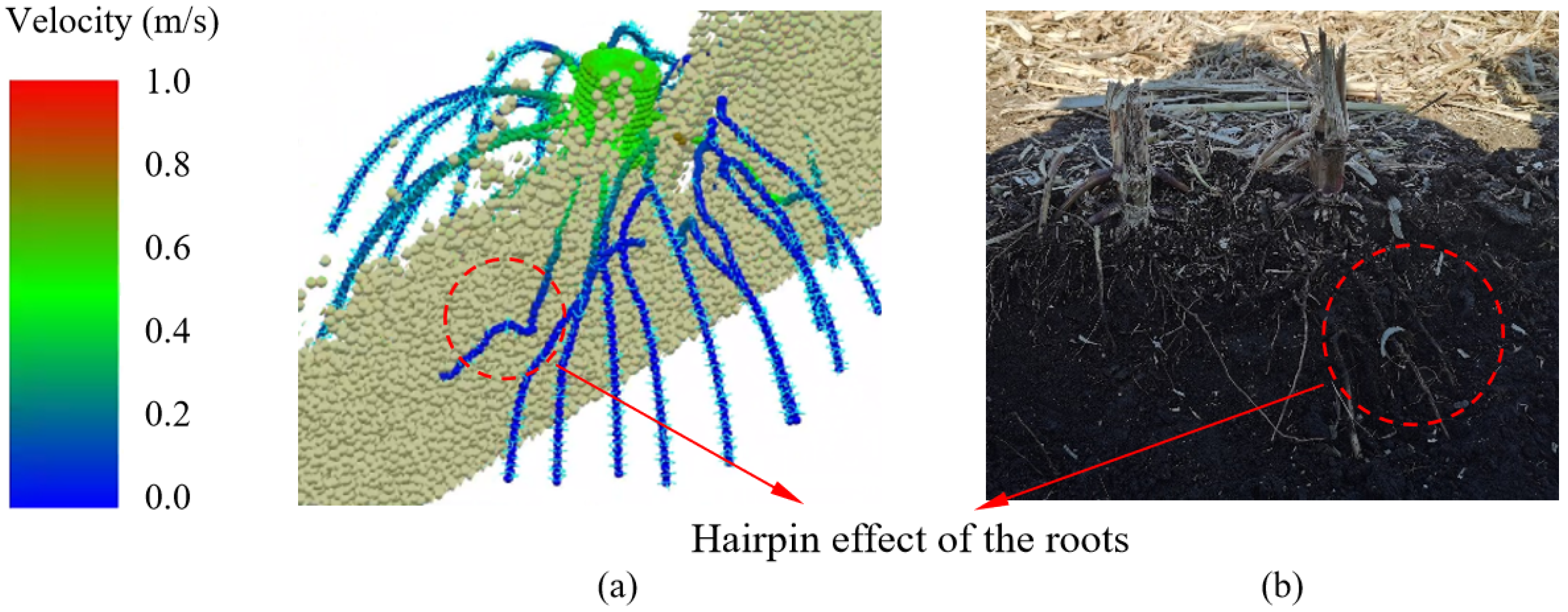
It is worth noting that during the entire stubble-breaking process, the roots that were not fractured could be pushed and embedded into the deep soil. The root dragging distance of these roots could be infinite and immeasurable. The roots and soil underwent irreversible deformation, which could easily lead to holes in the seeding furrow, resulting in the hairpin effect of the root (Figure 9a) [34]. These phenomena were observed during field experiments (Figure 9b). The hairpin effect led to poor contact between seeds and soil, thereby reducing seed germination rates and affecting the growth of maize.
Due to the significant influence of design parameters and operating parameters on factors such as resistance of the disc coulter and fracture of the root, it was necessary to analyze the key factors that affected stubble-breaking operations.

4.3. The Influence of Key Factors on the Stubble-Breaking Operation

4.3.1. The Influence of Different Types of Disc Coulters on the Stubble-Breaking Operation

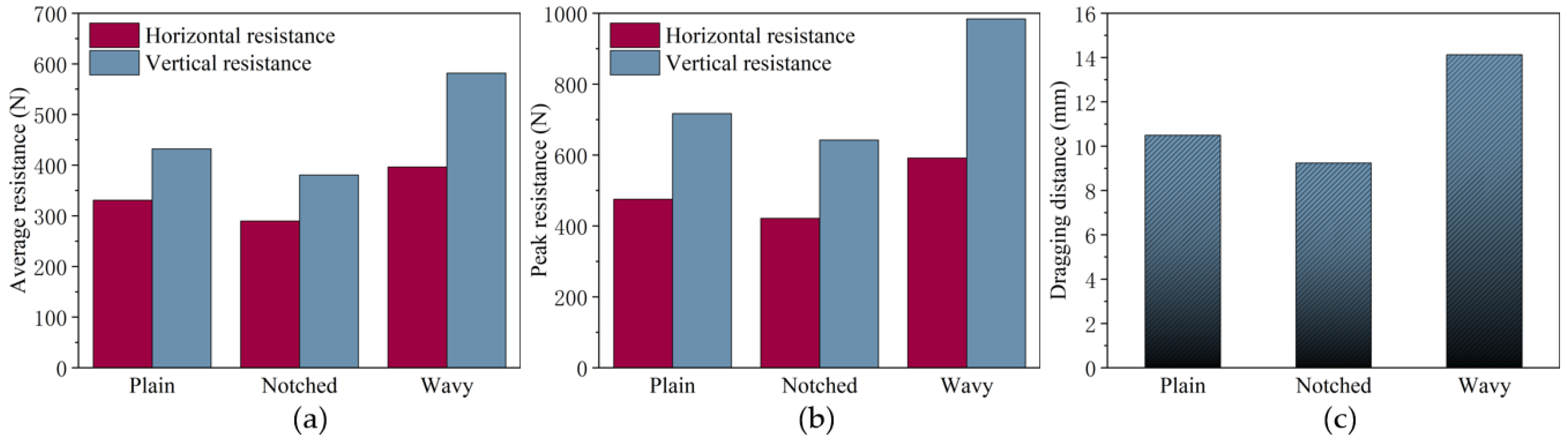
The results of the DEM simulation (Figure 10) indicated that the resistance of the notched disc coulter, plain disc coulter, and wavy disc coulter increased sequentially. Compared to the plain disc coulter, the average and peak horizontal resistance of the notched disc coulter decreased by 12.44% and 11.34%, the average and peak vertical resistance decreased by 11.96% and 10.39% (Figure 10a,b), and the root dragging distance decreased by 11.96% (Figure 10c). The average and peak horizontal resistance of the wavy disc coulter increased by 19.80% and 24.49% (Figure 10a,b), the average and peak vertical resistance increased by 34.56% and 37.25%, and the root dragging distance increased by 34.56% (Figure 10c).
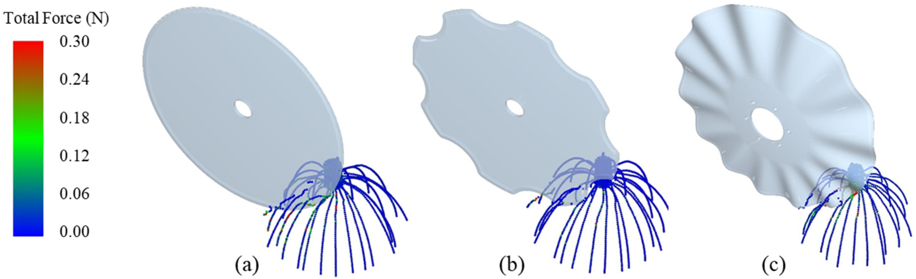
The DEM cloud diagram indicated that, compared to the plain disc coulter, the notched disc coulter had lower resistance due to the following reasons: First, maize roots were constrained within the notch. On the one hand, the notch could effectively “grab” and fix the maize roots, preventing them from being pushed as a whole and being cut off timely, avoiding the formation of large soil blocks or residue accumulation in front of the working parts, and reducing resistance. On the other hand, the fixed roots were pushed into deeper soil layers (Figure 11a,b). The soil in the deeper layer was firm and provided better support for the roots, making them easier to fracture [32]. Consequently, the resistance of notched disc coulters was lower. Second, the notched structure of the coulter led roots to contact the disc coulter edge at different times. The roots outside the notch contacted the edge of the disc coulter earlier and had greater deformation compared to those inside the notch, which contacted later and deformed less (Figure 11b). The difference in the time of deformation and fracture between the inner and outer roots of the notch reduced the cumulative effect of root-cutting force. Consequently, the peak resistance of notched disc coulters was lower. This conclusion could also explain the reason for the decrease in the resistance of other notched disc coulters with the similar structure. Third, since the cutting edge of the notched disc coulter was discontinuous, the contact with stubble was not gradual but involved an impact action. In contrast, due to the greater impact force of the notched disc coulter on the maize root, the bonds between root particles quickly reached critical force (7.32 N) and broke, resulting in shorter root dragging distances and eliminating the reinforcement effect of the roots on the soil, thereby reducing the stubble-breaking resistance. In contrast, the wavy disc coulter had the greatest contact area with the soil compared to the other two types. Its cutting edge was the longest and contacted more roots within a unit angle of rotation (Figure 11c). Consequently, under the combined effects of pure cutting force [35] and root-cutting force [32], wavy disc coulters had the highest resistance.

4.3.2. The Influence of Disc Coulter Radius on the Stubble-Breaking Operation

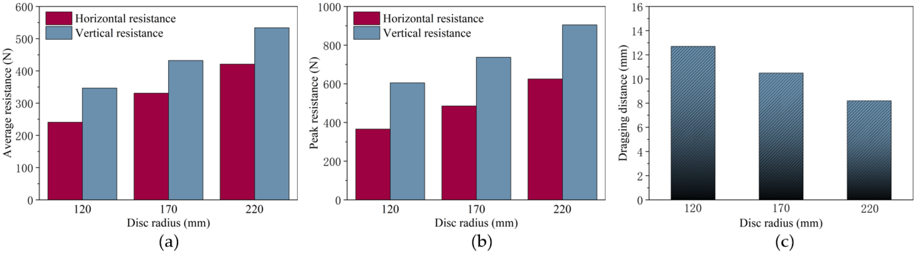
As the radius of the disc coulter increased, the horizontal and vertical resistances of the disc coulter could significantly increase (Figure 12). Compared to the disc coulter with a radius of 170 mm, the average and peak horizontal resistance of the disc coulter with a radius of 120 mm decreased by 27.22% and 24.62%, the average and peak vertical resistance decreased by 19.75% and 17.94% (Figure 12a,b), and the root dragging distance increased by 20.95% (Figure 12c). The average and peak horizontal resistance with a disc radius of 220 mm increased by 27.22% and 28.72%, the average and peak vertical resistance increased by 23.52% and 22.75% (Figure 12a,b), and the root dragging distance decreased by 21.90% (Figure 12c). In summary, as the radius of the disc increased, the average resistance and peak resistance also increased, and the root dragging distance decreased.
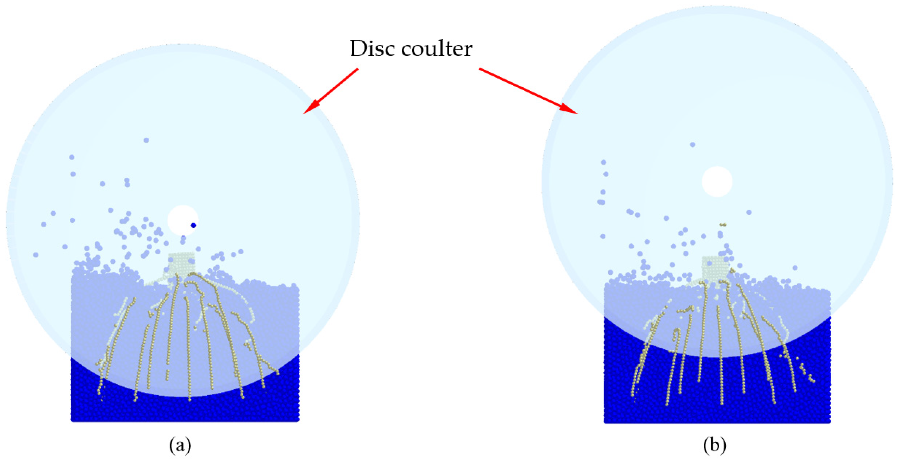
The DEM cloud diagram indicated that a disc coulter with a greater radius would contact more roots simultaneously (Figure 13a), leading to a more significant cumulative effect of root-cutting force [20] and higher resistance on the disc coulter. This was consistent with the research of Bai and Liu et al. [20,32]. According to the pure cutting theory [35], the greater the radius of the disc coulter, the greater the contact area between the disc coulter and the soil, and the greater the pure cutting force. This is another reason why disc coulters with greater disc radius face higher resistance. Higher resistance not only made the stubble-breaking device faced greater energy consumption, but a sudden increase in the peak resistance also led to unstable tillage depth, which had a negative impact on seeding operations. In addition, as for the disc coulter with a greater radius, the component of the velocity vector on the cutting edge facing towards the deeper soil layer was higher. Therefore, roots tended to be pushed into deeper soil layers. The roots pushed into deep soil could obtain better support and were more easily cut off. According to previous research [20], the cutting force of a disc coulter was mainly composed of soil reaction force, root tensile force, and friction force. The soil reaction force on the root that was cut off in deep soil was relatively higher, so the axial tension on the root was relatively lower, the root dragging distance was shorter, the possibility of damage to the root–soil interface was lower, and the root was more easily cut off efficiently. Therefore, disc coulters with a larger radius had better tillage performance. In summary, to address varying agronomic requirements, there was an optimal radius for the disc coulter, which enabled it to meet the design requirements of lower resistance and excellent stubble-breaking performance.

4.3.3. The Influence of Tillage Speed on the Stubble-Breaking Operation

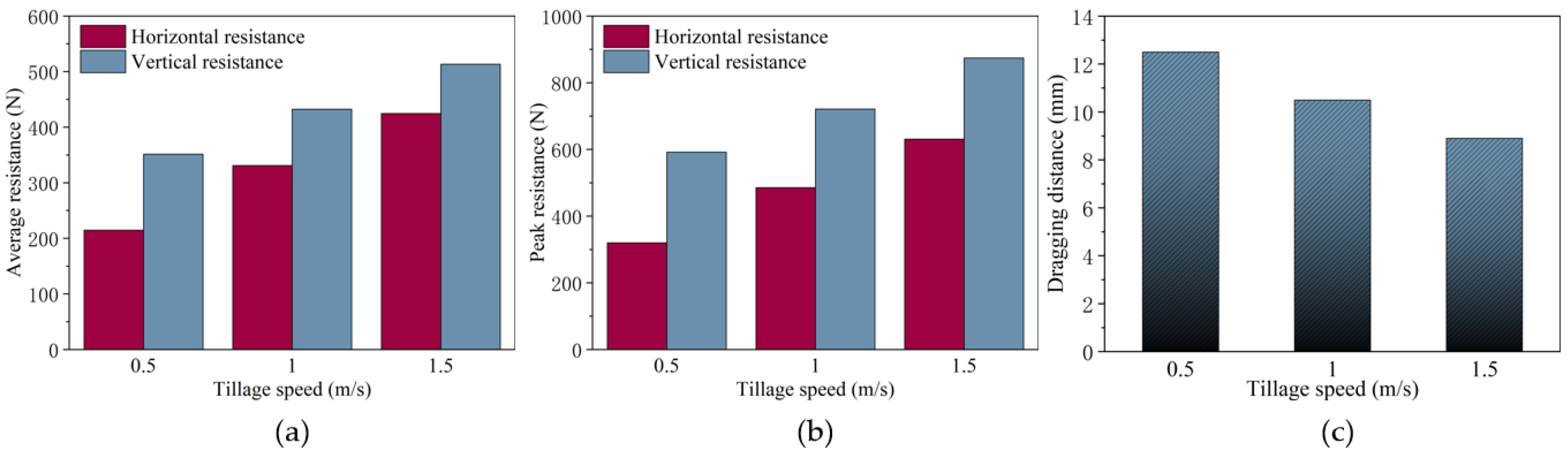
As the tillage speed of the disc coulter increased, the horizontal and vertical resistance of the disc coulter could significantly increase (Figure 14). Compared to the disc coulter with a tillage speed of 1.0 m/s, the average and peak horizontal resistance of the disc coulter with a tillage speed of 0.5 m/s decreased by 35.17% and 34.10%, the average and peak vertical resistance decreased by 18.73% and 17.89% (Figure 14a,b), and the root dragging distance increased by 19.05% (Figure 14c). The average and peak horizontal resistance of the disc coulter with a tillage speed of 1.5 m/s increased by 28.27% and 29.95%, the average and peak vertical resistance increased by 18.73% and 21.22% (Figure 14a,b), and the root dragging distance decreased by 15.24% (Figure 14c). In summary, as the tillage speed increased, the average and peak resistance also increased, and the root dragging distance decreased.
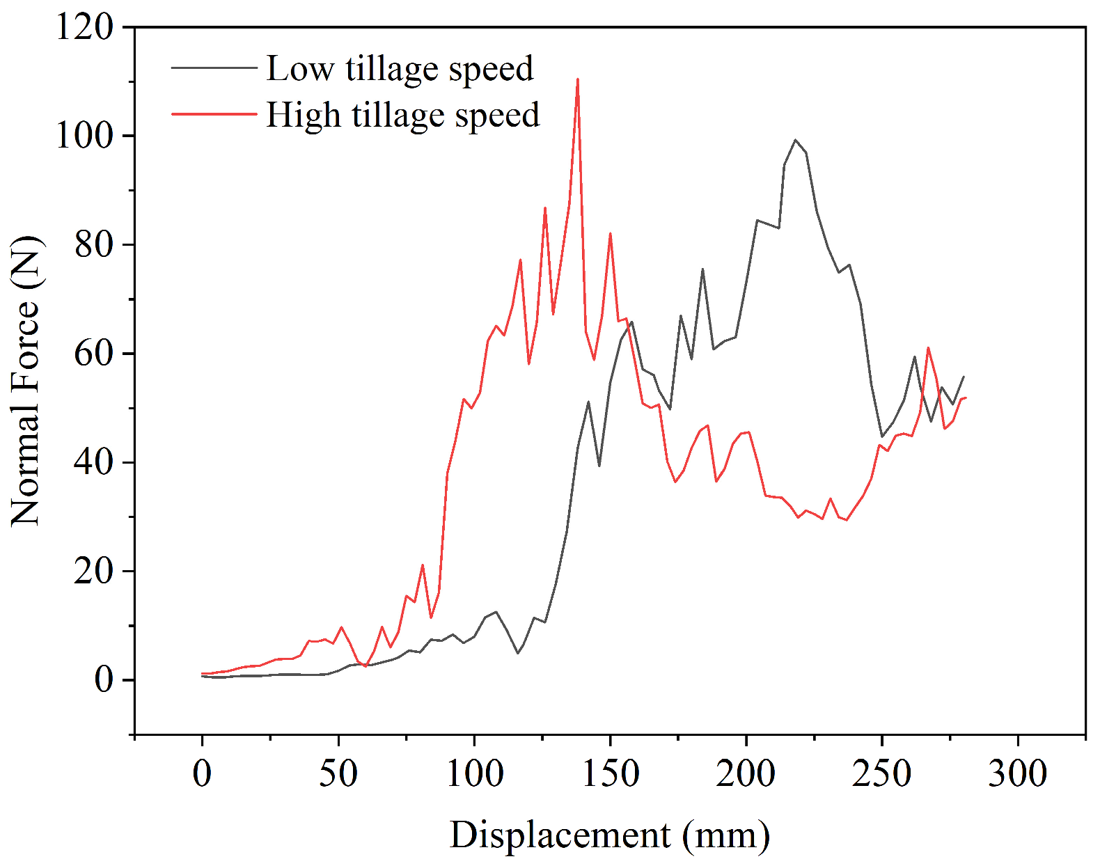
Subrata Karmakar et al. [36] indicated that as the plate compression speed increased, both the soil reaction force on the plate and soil stiffness rose accordingly. DEM simulation results indicated that when the tillage speed of the disc coulter increased from 0.5 m/s to 2.5 m/s, the soil reaction force on roots and their growth rate significantly increased (Figure 15). Due to the fact that the soil reaction force was the main component of resistance of the disc coulter [20], the higher the speed of the disc coulter, the greater the tillage resistance. Previous studies showed that the greater the contact force applied to the roots, the easier the roots were to fracture [20]. Therefore, under high-speed stubble-breaking conditions, due to the great growth rate of soil reaction force within the unit dragging distance of the roots, the contact force applied to the roots significantly increased, and the roots would be cut off at a shorter dragging distance. Thus, the performance of the disc coulter for high-speed operation was excellent. According to the research of Liu et al. [20], the proportion of tension on roots with shorter dragging distance relative to the root-cutting force was lower. This reduced the possibility of the failure of root–soil interface, reduced the number of dragging and exposure of roots, and made the cutting surface of maize stubble smoother. However, disc coulters operating at higher speeds could face greater pure cutting forces, meaning they had higher resistance during high-speed stubble-breaking operations. Therefore, the high-speed disc coulter needed to face greater energy consumption and impact force during the stubble-breaking operation. A higher impact force not only shortened the service life of the stubble-breaking device but also affected the stability of tillage depth and the germination of seeds. In summary, for high-speed stubble-breaking operations, disc coulters with strong stubble-breaking performance and sufficient counterweights should be used. Key components should also be reinforced to enhance the operational stability of the stubble-breaking device and extend the service life of the tillage equipment.

4.3.4. The Influence of Tillage Depth on the Stubble-Breaking Operation

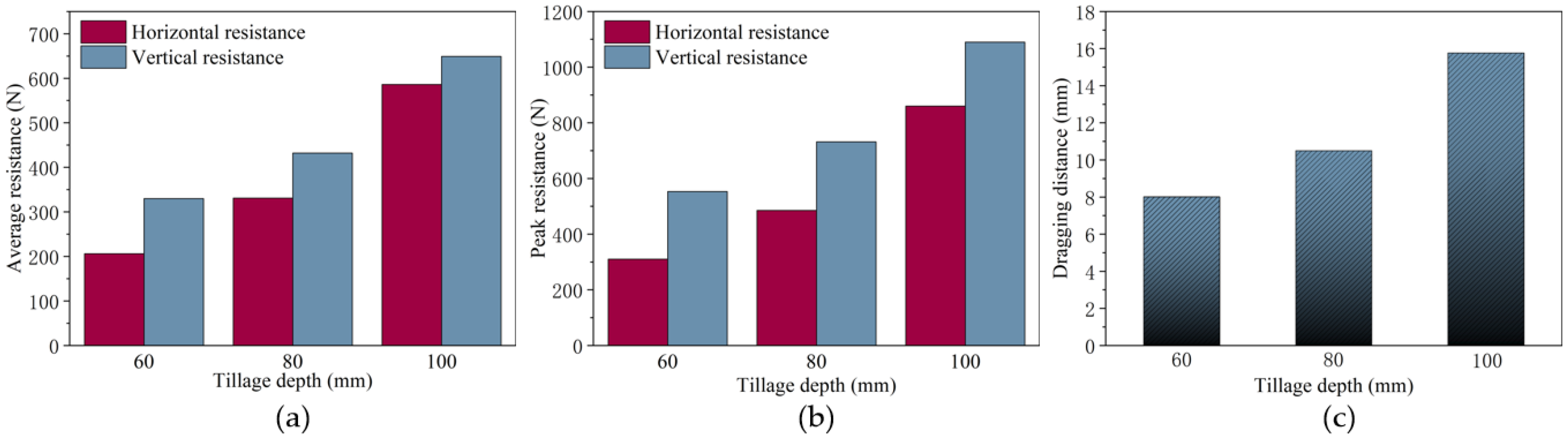
As the tillage depth of the disc coulter increased, the horizontal and vertical resistance of the disc coulter also increased (Figure 16). Compared to the disc coulter with a tillage depth of 80 mm, the average and peak horizontal resistance decreased by 37.68 and 36.08% with a tillage depth of 60 mm, the average and peak vertical resistance decreased by 23.69% and 24.45% (Figure 16a,b), and the root dragging distance decreased by 23.69% (Figure 16c). The average and peak horizontal resistance of the disc coulter increased by 77.12% and 77.32% with a tillage depth of 100 mm, and the average and peak vertical resistance increased by 50.16% and 48.91% (Figure 16a,b), and the root dragging distance increased by 50.16% (Figure 16c). In summary, as the tillage speed increased, the average and peak resistance also increased, and the root dragging distance increased.
According to the simulation results, although the cutting edge of the disc coulter used for the deep soil layer (Figure 17a) could completely cut off the maize stubble, due to the deep tillage, the disc coulter had a great contact area with the soil and higher pure cutting force; meanwhile, the disc coulter would also come into contact with a large number of roots, and the cumulative effect of the root-cutting force was more significant. The above reasons made the resistance of the disc stubble-breaking device higher. As for the cutting edge of the disc coulter used for shallow soil layer (Figure 17b), due to the low soil reaction force applied to the roots in the shallow soil layer, if the roots fractured, the tensile force on the roots would be higher, and the root dragging distance would be longer; if the roots did not fracture, it would be pushed into the seedbed, causing a hairpin effect and affecting seed germination. In addition, due to insufficient dragging distance of the roots in deep soil layer, it was difficult to cut off the roots, resulting in missed cutting. In summary, crop residue management should adopt optimal tillage depths based on root structure and agronomic requirements to enhance operational quality.

5. Conclusions

This study developed a DEM-MBD coupling model for the interaction between disc coulters and maize root–soil composites. The model was validated through soil bin tests and field experiments. Using the DEM-MBD coupling model, the interaction between disc coulters and maize root–soil composites was investigated. The conclusions were as follows:
  • Due to the significant strengthening effect of roots on soil, the disc stubble-breaking device needed to face greater resistance. During the stubble-breaking operation, the greater the deformation of the roots that came into contact with the disc coulter, and the greater the number of roots distributed along its cutting edge, the greater the resistance encountered by the disc coulter. If the roots could not be cut off during stubble-breaking operation and face irreversible deformation, it would lead to the holes in the planting furrow. The roots that could not be cut off would be pushed and embedded into the deep soil layer, resulting in the root hairpin effect;
  • Compared to plain disc coulters, the difference in the time of deformation and fracture between the inner and outer roots of the notch reduced the cumulative effect of root-cutting force. The discontinuous edge curve of the notched disc coulter had an impact effect, which made the root more prone to fracture. Therefore, notched disc coulters had lower tillage resistance and better stubble-breaking performance; wavy disc coulters had higher tillage resistance. The contact area between the disc coulter and the soil was larger compared to the other two types of disc coulters, the cutting edge was longer per unit rotation angle, and there were more roots in contact. Therefore, under the cumulative of pure cutting force and root cutting force, the resistance of the wavy disc coulter was higher;
  • The disc coulter with a greater radius had more contact points with the roots and a greater contact area with the soil. As a result, it met greater resistance during stubble-breaking operations. However, these disc coulters tended to push the roots deeper into the soil with higher solidity, thus having better stubble-breaking performance. Therefore, to address varying agronomic requirements, there existed an optimal radius for the disc coulter that could meet the design requirements of lower resistance and excellent stubble-breaking performance;
  • In high-speed stubble breaking operations, the resistance of the disc coulter on the roots would significantly increase. Although this could significantly increase the impact force of the disc coulter on the stubble, which was more conducive to stubble-breaking operation, it would also reduce operational stability and service life and affect seeding quality. Therefore, when carrying out high-speed stubble-breaking operations, it was necessary to equip stubble-breaking coulters with excellent stubble-breaking performance and sufficient counterweights. In addition, key components needed to be strengthened to improve the stability of the stubble-breaking device and the service life of the tillage equipment;
  • As the soil reaction force increased with the depth of the soil; therefore, the cutting edge of disc coulter used for the deep soil layer would come into contact with more roots and more soil, leading to a greater resistance. In contrast, the cutting edge of a disc coulter used for shallow soil layers required a longer dragging distance to cut off the roots. If the roots could not be cut off, they would be pushed into the seedbed, hindering seed germination. Therefore, according to the structure of the crop roots and agronomic requirements, the depth of the tillage operation should be suitable for the stubble-breaking operation to improve the quality of the operation.
This study revealed the interaction mechanism between the disc coulter and the maize root–soil composite, providing a theoretical basis for the design of stubble-breaking devices. However, to obtain a universal design theory and develop a quantitative model to optimize the stubble-breaking component, it is necessary to verify the universality of the model on different platforms, as well as to conduct in-depth research on the influence of complex agricultural environmental factors such as soil moisture content, root rot, and root–soil interface mechanical properties, and the operating conditions of tillage equipment on the interaction.

Author Contributions

Conceptualization, X.L.; methodology, X.L., Z.G., Z.T., M.H., P.G. and Z.X.; software, X.L., Z.T. and Z.X.; validation, X.L., Z.T. and Z.X.; formal analysis, X.L., Z.G., Z.T., M.H., P.G., Z.T. and Z.X.; investigation, X.L., Z.G., Z.T., M.H., P.G. and Z.X.; resources, Y.M. and Z.X.; data curation, X.L., Z.G., Z.T., M.H., P.G. and Z.X.; writing—original draft preparation, X.L.; writing—review and editing, X.L., Z.G., Z.T., M.H., P.G., Y.M. and Z.X.; visualization, X.L., Z.G., Z.T., M.H., P.G. and Z.X.; supervision, Y.M. and Z.X.; project administration, Y.M.; funding acquisition, Y.M. and Z.X. All authors have read and agreed to the published version of the manuscript.

Funding

This work was supported by the National Natural Science Foundation of China [grant number 52275288], the National Key Research and Development Program of China [grant number 2023YFD2000903].

Institutional Review Board Statement

Not applicable.

Data Availability Statement

The original contributions presented in the study are included in the article; further inquiries can be directed to the corresponding author.

Conflicts of Interest

The authors declare no conflicts of interest.

References

  1. Zhang, X.; Yun, Y.; Liu, C.; Xin, X.; Yang, W. Conservation Tillage Exerts Diverse Pathways to Sequester Organic Carbon in Fluvo-Aquic Soils of the North China Plain. Soil Tillage Res. 2025, 254, 106730. [Google Scholar] [CrossRef] [Scilit]
  2. Gao, W. Conservation Farming System in China, 1st ed.; China Agricultural University Press: Beijing, China, 2011. [Google Scholar]
  3. Gebhardt, M.R.; Daniel, T.C.; Schweizer, E.E.; Allmaras, R.R. Conservation Tillage. Science 1985, 230, 625–630. [Google Scholar] [CrossRef] [Scilit]
  4. Schwarz, M.; Rist, A.; Cohen, D.; Giadrossich, F.; Egorov, P.; Büttner, D.; Stolz, M.; Thormann, J.J. Root Reinforcement of Soils under Compression. J. Geophys. Res. Earth Surf. 2015, 120, 2103–2120. [Google Scholar] [CrossRef] [Scilit]
  5. Wu, T.H. Study of Soil-Root Interaction. J. Geotech. Eng. 1989, 114, 1351–1375. [Google Scholar] [CrossRef] [Scilit]
  6. Xie, M. A Study on the Soil Mechanical Role of Tree Roots in the Stability of Slopes. J. Soil Water Conserv. 1990, 4, 7–14. [Google Scholar] [CrossRef]
  7. Wang, Q.; Cao, X.; Wang, C.; Li, H.; He, J.; Lu, C. Research Progress of No/Minimum Tillage Corn Seeding Technology and Machine in Northeast Black Land of China. Trans. Chin. Soc. Agric. Mach. 2021, 52, 1–15. [Google Scholar] [CrossRef]
  8. He, J.; Li, H.; Chen, H.; Lu, C.; Wang, Q. Research Progress of Conservation Tillage Technology and Machine. Trans. Chin. Soc. Agric. Mach. 2018, 49, 1–19. [Google Scholar]
  9. Torotwa, I.; Ding, Q.; Makange, N.R.; Liang, L.; He, R. Performance Evaluation of a Biomimetically Designed Disc for Dense-Straw Mulched Conservation Tillage. Soil Tillage Res. 2021, 212, 105068. [Google Scholar] [CrossRef] [Scilit]
  10. Zeng, Z.; Chen, Y. Performance Evaluation of Fluted Coulters and Rippled Discs for Vertical Tillage. Soil Tillage Res. 2018, 183, 93–99. [Google Scholar] [CrossRef] [Scilit]
  11. Zhang, S.; Jia, X.; Dong, J.; Wang, X.; Zhao, H.; Chen, X.; Zhang, Z.; Huang, Y.; Shi, J. Optimization of Operating Angles of Disc Coulters for Maize Residue Management Using Discrete Element Method. Comput. Electron. Agric. 2024, 218, 108691. [Google Scholar] [CrossRef] [Scilit]
  12. Karayel, D. The Effect of Furrow Opener and Disc Coulter Configurations on Seeding Performance under Different Residue Cover Densities. AgriEngineering 2024, 6, 1277–1288. [Google Scholar] [CrossRef] [Scilit]
  13. Kogut, Z.; Sergiel, L.; Zurek, G. The Effect of the Disc Setup Angles and Working Depth on Disc Harrow Working Resistance. Biosyst. Eng. 2016, 151, 328–337. [Google Scholar] [CrossRef] [Scilit]
  14. Zahid, M.; Celik, A. Disc Angle and Tilt Angle Effects on Forces Acting on a Single-Disc Type No-till Seeder Opener. Soil Tillage Res. 2019, 194, 104304. [Google Scholar] [CrossRef] [Scilit]
  15. Mickovski, S.B.; Stokes, A.; van Beek, R.; Ghestem, M.; Fourcaud, T. Simulation of Direct Shear Tests on Rooted and Non-Rooted Soil Using Finite Element Analysis. Ecol. Eng. 2011, 37, 1523–1532. [Google Scholar] [CrossRef] [Scilit]
  16. Schwarz, M.; Giadrossich, F.; Cohen, D. Modeling Root Reinforcement Using a Root-Failure Weibull Survival Function. Hydrol. Earth Syst. Sci. 2013, 17, 4367–4377. [Google Scholar] [CrossRef] [Scilit]
  17. Mickovski, S.B.; Ennos, A.R. Model and Whole-Plant Studies on the Anchorage Capabilities of Bulbs. Plant Soil 2003, 255, 641–652. [Google Scholar] [CrossRef] [Scilit]
  18. Schwarz, M.; Cohen, D.; Or, D. Root-Soil Mechanical Interactions during Pullout and Failure of Root Bundles. J. Geophys. Res. Earth Surf. 2010, 115, F04035. [Google Scholar] [CrossRef] [Scilit]
  19. Zhao, J.; Lu, Y.; Wang, X.; Zhuang, J.; Han, Z. A Bionic Profiling-Energy Storage Device Based on MBD-DEM Coupled Simulation Optimization Reducing the Energy Consumption of Deep Loosening. Soil Tillage Res. 2023, 234, 105824. [Google Scholar] [CrossRef] [Scilit]
  20. Liu, X.; Gao, P.; Jiang, X.; Guo, M.; Wang, Y.; Ma, Y. Study on the Interaction Mechanism between Stubble-Breaking Blades and Unidirectional Maize Root-Soil Composites. Biosyst. Eng. 2025, 256, 104190. [Google Scholar] [CrossRef] [Scilit]
  21. Zhao, X.; Zhang, Z.; Huang, Q.; Zhang, G. Cutting Performance of Corn Root-Soil Composite. Trans. Chin. Soc. Agric. Mach. 2013, 44, 126–132. [Google Scholar] [CrossRef]
  22. Zheng, L.; Luo, X.; Zeng, S.; Wang, Z.; Liu, C.; Qi, X. Shear Characteristics of Rice Root-Soil Composite. Trans. Chin. Soc. Agric. Mach. 2017, 48, 63–71. [Google Scholar] [CrossRef]
  23. Yuan, Y.; Du, M.; Zhou, Y.; Yang, Y.; Zhang, X.; Zhao, S. FEM-SPG Coupling Modelling and Reinforced Soil Effect of Maize Root-Soil Composite. Biosyst. Eng. 2025, 259, 104293. [Google Scholar] [CrossRef] [Scilit]
  24. Zhang, S.; Huang, Y.; Zhao, H.; Fu, Z.; Liu, Z.; Shi, J. Design and Experiment of Cutting and Throwing Combined Anti-Blocking Device for Wide-Seedbed Seeding of Wheat. Trans. Chin. Soc. Agric. Mach. 2024, 55, 40–52. [Google Scholar] [CrossRef]
  25. Tamás, K.; Bernon, L. Role of Particle Shape and Plant Roots in the Discrete Element Model of Soil–Sweep Interaction. Biosyst. Eng. 2021, 211, 77–96. [Google Scholar] [CrossRef] [Scilit]
  26. Zou, L.; Yan, D.; Niu, Z.; Yuan, J.; Cheng, H.; Zheng, H. Parametric Analysis and Numerical Optimisation of Spinach Root Vibration Shovel Cutting Using Discrete Element Method. Comput. Electron. Agric. 2023, 212, 108138. [Google Scholar] [CrossRef] [Scilit]
  27. Liu, X.; Qi, H.; Wang, S.; Xu, Z.; Gao, P.; Fu, D.; Ma, Y. The Design and Experimentation of a Wing-Shaped Stubble-Breaking Device for Maize Stubbles. Agriculture 2024, 14, 2108. [Google Scholar]
  28. Zhang, S.; Zhao, H.; Wang, X.; Dong, J.; Zhao, P.; Yang, F.; Chen, X.; Liu, F.; Huang, Y. Discrete Element Modeling and Shear Properties of the Maize Stubble-Soil Complex. Comput. Electron. Agric. 2023, 204, 107519. [Google Scholar] [CrossRef] [Scilit]
  29. Du, J.; Heng, Y.; Zheng, K.; Luo, C.; Zhu, Y.; Zhang, J.; Xia, J. Investigation of the Burial and Mixing Performance of a Rotary Tiller Using Discrete Element Method. Soil Tillage Res. 2022, 220, 105349. [Google Scholar] [CrossRef] [Scilit]
  30. Zhang, S.; Huang, Y.; Gao, X.; Bi, Y.; Dong, J.; Zhao, H.; Zhao, P.; Jia, X. Evaluating the Influence of Straight-Plain Types of Rotary Tiller Blades with Various Edge Curves on Maize Residue Using DEM. Biosyst. Eng. 2025, 250, 49–61. [Google Scholar] [CrossRef] [Scilit]
  31. Che, H.; Zhou, H.; Li, Z.; Wang, X.; Wang, X.; Wei, Z.; Li, Y.; Zhang, Y. Evaluation of the Working Performance of Different Digging Shovels Based on the Maize Root-Soil Complex Model. Biosyst. Eng. 2025, 260, 104316. [Google Scholar] [CrossRef] [Scilit]
  32. Bai, X.; Lin, J.; Lü, C.; Hu, Y. Analysis and Experiment on Working Performance of Disc Coulter for No-Tillage Seeder. Trans. Chin. Soc. Agric. Eng. 2014, 30, 1–9. [Google Scholar] [CrossRef]
  33. Shao, M.R.; Jiang, N.; Li, M.; Howard, A.; Lehner, K.; Mullen, J.L.; Gunn, S.L.; McKay, J.K.; Topp, C.N. Complementary Phenotyping of Maize Root System Architecture by Root Pulling Force and X-Ray Imaging. Plant Phenomics 2021, 2021, 9859254. [Google Scholar] [CrossRef] [Scilit] [PubMed]
  34. Moyer, J.R.; Nitschelm, J.; Regitnig, P.; Blackshaw, R.E.; Huang, H.C.; Chang, C. Effect of Tillage System and Crop Sequence on Irrigated Sugarbeet Production. Can. J. Plant Sci. 2004, 84, 739–747. [Google Scholar] [CrossRef] [Scilit]
  35. McKyes, E. Soil Cutting and Tillage; Elsevier: Amsterdam, The Netherlands, 1985; ISBN 044460104X. [Google Scholar]
  36. Karmakar, S.; Lal Kushwaha, R. CFD Simulation of Soil Forces on a Flat Tillage Tool. In Proceedings of the 2005 ASAE Annual International Meeting, Tampa, FL, USA, 17 July 2005; Volume 0300. [Google Scholar]
Figure 1. DEM model of maize root–soil composite.
Agriculture 16 00270 g001
Figure 2. DEM-MBD coupling model of disc stubble-breaking operations: (a) MBD model of disc stubble-breaking device; (b) DEM-MBD coupling model of disc stubble-breaking operation and each disc coulter.
Agriculture 16 00270 g002
Figure 3. The dragging distance of the maize root.
Agriculture 16 00270 g003
Figure 4. Soil bin tests. (a) Experiment site and (b) experimental equipment; I: torque sensor; II: soil bin trolley testing system; III: three-dimensional force sensor; IV: disc coulter.
Agriculture 16 00270 g004
Figure 5. Field experiments. (a) Field experiment site and (b) experimental equipment; I: torque sensor; II: disc coulter.
Agriculture 16 00270 g005
Figure 6. Force-displacement curve of disc coulters: (a) the curve of horizontal resistances for simulation and experiment; (b) the curve of horizontal resistances for different disc coulters; (c) the curve of vertical resistances for different disc coulters.
Agriculture 16 00270 g006
Figure 7. DEM cloud diagram of the interaction between the disc coulter and the maize root–soil composite.
Agriculture 16 00270 g007
Figure 8. A DEM cloud diagram of motion and stress of the root and soil during the stubble-breaking operation.
Agriculture 16 00270 g008
Figure 9. Hairpin effect of the roots: (a) simulation result, (b) field experiment results.
Agriculture 16 00270 g009
Figure 10. The influence of disc coulter types on the average resistance, the peak resistance, and dragging distance: (a) the influence of types of disc coulters on average resistance; (b) the influence of types of disc coulters on peak resistance; (c) the influence of types of disc coulters on dragging distance.
Agriculture 16 00270 g010
Figure 11. The interaction process between the disc coulter and the maize root–soil composite: (a) plain disc coulter; (b) notched disc coulter; (c) wavy disc coulter.
Agriculture 16 00270 g011
Figure 12. The influence of disc radius on the average resistance, the peak resistance, and dragging distance: (a) the influence of disc radius on average resistance; (b) the influence of disc radius on peak resistance; (c) the influence of disc radius on dragging distance.
Agriculture 16 00270 g012
Figure 13. The interaction between disc coulters with different disc radius and maize root–soil composites: (a) disc radius of 220 mm; (b) disc radius of 170 mm.
Agriculture 16 00270 g013
Figure 14. The influence of tillage speed on the average resistance, the peak resistance, and dragging distance: (a) the influence of tillage speed on average resistance; (b) the influence of tillage speed on peak resistance; (c) the influence of tillage speed on dragging distance.
Agriculture 16 00270 g014
Figure 15. The soil reaction force on roots–time curve at different tillage speeds.
Agriculture 16 00270 g015
Figure 16. The influence of tillage depth on the average resistance, the peak resistance, and dragging distance: (a) the influence of tillage depth on average resistance; (b) the influence of tillage depth on peak resistance; (c) the influence of tillage depth on dragging distance.
Agriculture 16 00270 g016
Figure 17. Interaction between disc coulters and maize root–soil composites at different tillage depths: (a) tillage depth of 60 mm; (b) tillage depth of 100 mm.
Agriculture 16 00270 g017
Table 1. Key parameters of the DEM model.
ParameterMaterialValue
Density (kg/m3)root107
soil2620
65Mn steel7650
Poisson’s ratioroot0.25
soil0.30
65Mn steel0.30
Young’s modulus (Pa)root3.00 × 107
soil2.60 × 107
65Mn steel2.50 × 1011
Normal stiffness of bond (N/m3)soil–soil1.19 × 107
root–root7.74 × 109
soil–root4.00 × 107
Critical stresses of bond (Pa)soil–soil1.00 × 107
root–root7.00 × 108
soil–root1.00 × 107
Bond disc radius (mm)soil–soil0.66
root–root1.56
soil–root1.10
Surface energy coefficients (J/m2)soil–root3.38
Table 2. Key friction parameters of the DEM model.
ParameterMaterialValue
Coefficient of restitutionsoil–soil0.60
root–root0.65
soil–root0.65
soil–steel0.60
root–steel0.32
Coefficient of static frictionsoil–soil0.60
root–root0.62
soil–root0.55
soil–steel0.40
root–steel0.60
Coefficient of rolling frictionsoil–soil0.30
root–root0.25
soil–root0.32
soil–steel0.25
root–steel0.20
Table 3. Factors and levels of the design and the operation parameters of the disc coulter.
LevelsTypes of Disc CoulterDisc Radius
R/mm
Tillage Speed
v/(m/s)
Tillage Depth
h/mm
1Plain1200.560
2Notched1701.080
3Wavy2201.5100
Table 4. The average horizontal resistance of verification tests.
IndicatorsAverage Horizontal Resistance (N)
SimulationSoil Bin TestDeviationField ExperimentDeviation
Plain330.98364.56 ± 12.259.21%390.36 ± 22.2515.21%
Notched289.82337.47 ± 9.1214.12%403.20 ± 18.2528.12%
Wavy396.52485.04 ± 15.8718.25%576.76 ± 32.2531.25%
Table 5. The average vertical resistance of verification tests.
IndicatorsAverage Vertical Resistance (N)
SimulationSoil Bin TestDeviationField ExperimentDeviation
Plain432.30481.46 ± 10.3610.21%528.55 ± 25.2518.21%
Notched380.61428.23 ± 12.7611.12%515.17 ± 21.2526.12%
Wavy581.71720.39 ± 20.7819.25%778.21 ± 38.2525.25%
Disclaimer/Publisher’s Note: The statements, opinions and data contained in all publications are solely those of the individual author(s) and contributor(s) and not of MDPI and/or the editor(s). MDPI and/or the editor(s) disclaim responsibility for any injury to people or property resulting from any ideas, methods, instructions or products referred to in the content.