Article

Relative Localization Error Compensation Under Attitude Disturbances Based on Long Short-Term Memory Residual Learning and Adaptive Extended Kalman Filtering


1
College of Engineering, Nanjing Agriculture University, Nanjing 211800, China
2
School of Mechanical and Electronic Engineering, Nanjing Forestry University, Nanjing 210037, China
*
Authors to whom correspondence should be addressed.
Agriculture 2026, 16(17), 1931; https://doi.org/10.3390/agriculture16171931
Submission received: 30 July 2026 / Revised: 2 September 2026 / Accepted: 2 September 2026 / Published: 7 September 2026
(This article belongs to the Section Agricultural Technology)

Abstract

Tracked vehicles operating in hilly and mountainous agricultural environments are frequently subjected to pitch, roll, and vibration, which can introduce time-varying errors into ultra-wideband phase-difference-of-arrival (UWB-PDOA) relative localization. Aiming to improve localization accuracy under such disturbances, this study proposes a relative localization error compensation method that integrates long short-term memory (LSTM) residual learning with a residual-adaptive extended Kalman filter (RAEKF), referred to as LSTM-RAEKF. The proposed method combines UWB-PDOA measurements with inertial measurement unit information to learn disturbance-related localization residuals and adaptively compensate for relative position and theta observations before filtering. A UWB/IMU relative localization test bench was developed, and experiments were performed under static, pitch, roll, and vibration conditions. Across different fixed-point tests, the proposed method reduced the planar position RMSE and theta RMSE by 35.0–62.9% and 54.7–70.8%, respectively. Considering all experimental conditions, the position RMSE decreased from 4.00 cm to 1.81 cm, while the theta RMSE decreased from 5.64° to 2.17°, corresponding to reductions of 54.8% and 61.5%, respectively. Furthermore, LSTM-RAEKF outperformed the standard extended Kalman filter and the innovation-based adaptive estimation extended Kalman filter. Overall, these results demonstrate that LSTM-RAEKF can effectively suppress localization errors induced by attitude disturbances and provide stable relative localization information for subsequent tracked vehicle following control.

1. Introduction

Hilly and mountainous orchards, woodlands, and small agricultural plots feature uneven terrain, narrow access roads, and irregular working spaces. Tracked vehicles are particularly suitable for these environments due to their low ground pressure, strong trafficability, and slope adaptability. During autonomous following operations, accurate relative position, distance, and attitude information are crucial for speed regulation, path correction, and motion control. Therefore, UWB localization has been increasingly applied to agricultural machinery and mobile platform navigation. Xiao et al. established a UWB-based auxiliary navigation system for agricultural machinery [1]. Xie et al. designed a UWB navigation system for tracked agricultural machinery in small plots and examined the influence of base station deployment [2]. Yao et al. applied wireless positioning technology to path tracking for a greenhouse mobile platform [3]. These studies demonstrate the feasibility of UWB-based localization in agricultural applications. However, most existing studies have mainly emphasized navigation performance under relatively stable operating conditions but have not fully considered the degradation of localization accuracy attributed to vehicle attitude disturbances during operations on uneven terrain.
Compared with conventional range-only localization, UWB systems that incorporate angle information can provide richer observations for relative target-following applications. Heydariaan et al. estimated the angle of arrival using multi-antenna UWB signals [4]. Bae et al. introduced a component-wise error correction method for UWB-based target-following mobile robots to eliminate bias and high-frequency noise [5]. Brunacci et al. developed and analyzed a UWB relative localization system, aiming to reveal its capability for estimating relative positions [6]. However, UWB localization accuracy can be affected by platform motion, signal propagation conditions, antenna characteristics, and measurement geometry. Ferrero-Guillén et al. explored motion-induced errors in UWB localization under dynamic operating conditions [7], while Cao et al. investigated enhanced UWB positioning in complex GNSS-denied environments [8]. Liu et al. analyzed antenna phase-center offset calibration and multipoint time-latency estimation to reduce systematic errors [9]. Guo et al. combined dilution-of-precision analysis with Kalman filtering to enhance UWB localization performance in constrained environments [10]. Although these studies have addressed UWB localization errors from the perspectives of calibration, propagation, and filtering, the effects of continuous pitch, roll, and mechanical vibration on vehicle-mounted UWB-PDOA measurements remain underexplored. For tracked vehicles operating on uneven agricultural terrain, continuous attitude variations contribute to variations in the spatial relationship between UWB antennas, resulting in nonlinear and time-varying errors in range, angular observations, and relative coordinates.
Multi-sensor fusion and adaptive filtering methods have been widely investigated to improve localization continuity, accuracy, and robustness under dynamic conditions. He et al. developed an IMU–UWB localization method for mobile robots based on a dual-stage Kalman filtering strategy [11]. Osman et al. integrated adaptive covariance adjustment into GNSS–UWB fusion to enhance localization reliability in precision agriculture applications [12]. Wei et al. combined learning-based error compensation with an adaptive extended Kalman filter for IMU–UWB localization under NLOS conditions [13]. Gao et al. fused UWB measurements with onboard sensors for vehicle localization in complex traffic environments [14]. Sun et al. improved UWB-based robot localization using RTS-assisted Kalman filtering [15], while Xie and Zhang investigated high-precision UWB localization for agricultural machinery operating in unstructured field environments [16]. These studies indicate that multi-sensor fusion and adaptive filtering can substantially improve localization robustness. However, conventional filtering frameworks generally depend on predefined motion models and measurement covariance adjustment. Although adaptive covariance strategies can dynamically modify the confidence assigned to different measurements, they struggle to explicitly characterize nonlinear and temporally correlated residual errors caused by continuous vehicle attitude variations and mechanical vibration.
Data-driven approaches have recently provided new opportunities for learning complex temporal error characteristics in localization systems. Long short-term memory (LSTM) networks are particularly effective for extracting sequential dependencies from sensor measurements [17]. Poulose and Han applied LSTM networks to UWB-based indoor localization and improved positioning performance through temporal feature learning [18]. Tian et al. integrated an LSTM network with a Kalman filter to enhance UWB localization accuracy by learning nonlinear measurement errors [19]. Ren et al. further proposed an Attention-LSTM-based UWB/INS fusion framework for NLOS environments, revealing the effectiveness of attention mechanisms in extracting informative temporal features from multisource measurements [20]. Recent machine learning studies in agricultural applications have also demonstrated the potential of data-driven approaches for modeling nonlinear and dynamic processes [21]. However, existing learning-based localization methods mainly address general measurement errors, NLOS interference, or direct state estimation, while the residual evolution caused by vehicle platform attitude disturbances has rarely been considered. For tracked agricultural vehicles, UWB-PDOA measurement errors are strongly influenced by temporal variations in acceleration, angular velocity, pitch, roll, and yaw. Therefore, reliable relative localization in uneven agricultural environments requires a residual-learning framework that explicitly models disturbance-related localization errors, together with an adaptive filtering strategy that dynamically adjusts measurement uncertainty. Furthermore, recent machine learning studies in agricultural applications have demonstrated the effectiveness of data-driven methods in modeling nonlinear and dynamic processes, further highlighting the potential of intelligent algorithms for enhancing perception and control in agricultural equipment.
Accordingly, this study introduces an LSTM-RAEKF residual-adaptive fusion localization method for tracked vehicle following in hilly and mountainous environments. UWB-PDOA and IMU measurements are utilized in the construction of multisource sliding-window sequences, and disturbance-related localization residuals are predicted using an Attention-LSTM network. An adaptive residual gain and causal smoothing mechanism are introduced to suppress excessive correction fluctuations, while the process and measurement noise covariances are adjusted online based on residual characteristics and vehicle motion states. A relative localization test system is established to replicate target motion and vehicle platform attitude disturbances. Experiments are conducted under fixed-point attitude disturbances, straight-line motion, and turning conditions. The proposed method is then compared with raw UWB localization, LSTM-based residual correction, and conventional filtering methods to evaluate its effectiveness in reducing localization errors, trajectory fluctuations, and attitude estimation deviations.

2. Relative Localization System and Experimental Setup

2.1. Operating Environment and Tracked Vehicle Following Localization System

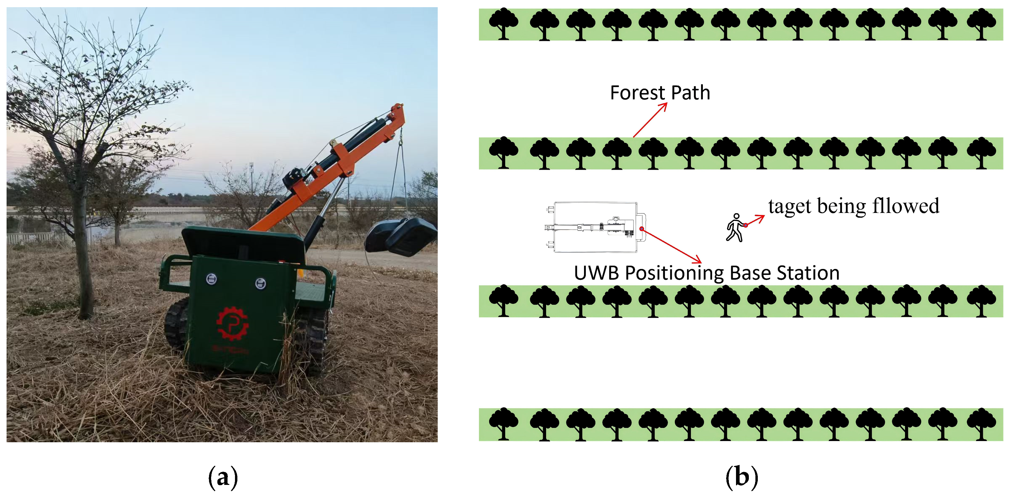
The tracked vehicle was developed for material transportation and target-following operations in hilly orchards, forest roads, and other unstructured agricultural environments. Figure 1a shows the operating area of the vehicle, which features slope variations, uneven ground surfaces, vegetation-induced occlusion, and locally soft surfaces. These environmental features impose high requirements on vehicle mobility and localization stability [22,23].
Figure 1b presents the following localization scenario. The UWB base station is rigidly mounted at the front of the tracked vehicle, while the UWB tag is carried by the followed target. During operation, the onboard UWB base station measures the relative distance, theta, and planar coordinates of the target relative to the vehicle. These relative-position observations are used as localization inputs for subsequent speed regulation, path correction, and motion control. In this study, a UWB-PDOA localization mode was utilized. The phase-difference-of-arrival (PDOA) measurement offers theta information based on the phase difference between receiving antennas. When the vehicle travels over uneven ground, slopes, or turning sections, pitch, roll, and vibration of the vehicle body can alter the spatial orientation of the UWB antenna array. Such alterations can result in fluctuations and time-varying errors in the raw UWB observations.
Accordingly, this study focuses on the accurate estimation and compensation for time-varying residual errors in UWB-PDOA relative localization under attitude disturbances of the vehicle. Aiming to address this problem, synchronized UWB-PDOA and IMU measurements are used to assess the relationship between platform motion and localization errors. The predicted residuals are then used to correct the raw relative-pose observations before adaptive state estimation. The objective is to improve the accuracy and stability of relative localization while simultaneously preserving the actual motion characteristics of the followed target.
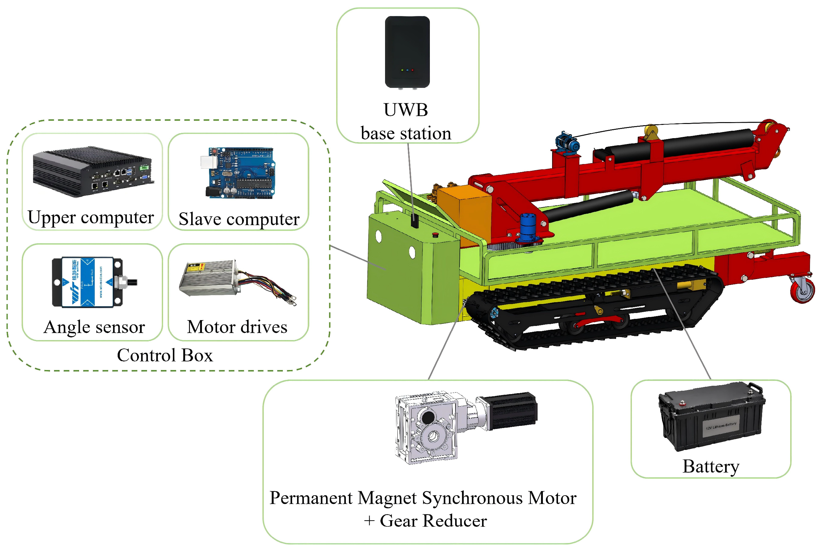
Figure 2 shows the platform and control system of the tracked vehicle. The system mainly comprises the tracked chassis, control box, UWB base station, IMU, motor drivers, permanent magnet synchronous motors, reducers, and battery. The UWB base station is used to determine the relative position of the followed target, while the IMU records the acceleration, angular velocity, and attitude angles of the vehicle platform. The control box enables data acquisition, communication, and algorithm processing. The motor drivers, motors, and reducers execute the driving commands of the vehicle. Within the control system, the upper-level computer receives and processes UWB and IMU data, while the lower-level controller regulates motor control and motion execution according to the control commands.

2.2. UWB/IMU Attitude-Disturbed Relative Localization Test Bench

Aiming to quantitatively assess the effects of attitude disturbances on UWB-PDOA relative localization, a UWB/IMU-based experimental test bench was developed, as shown in Figure 3. The test bench mainly encompasses a servo motor-driven linear guide system, a wearable UWB tag, a UWB anchor module, a six-degree-of-freedom motion platform, an inertial measurement unit, and a host computer. The servo motor-driven linear guide system supports controllable target motion, while the six-degree-of-freedom motion platform generates predefined pitch and roll disturbances within its operating range to reproduce representative vehicle attitude variations during uneven-terrain operation. According to the specifications of the motion platform, the pitch and roll angles were controlled within ±15° during the experiments.
The wearable UWB tag was mounted on the moving slider of the linear guide to simulate the relative motion of a followed target. The UWB anchor module and IMU were rigidly mounted on the six-degree-of-freedom motion platform, ensuring that the spatial configuration of the UWB antennas varied synchronously with the imposed platform attitude variations. During each experiment, the host computer simultaneously acquired UWB-PDOA measurements, IMU outputs, and linear-guide position feedback for subsequent error analysis and fusion-based localization.
The UWB-PDOA measurements were recorded at an output rate of 100 Hz during the experiments. The IMU sensor (HWT901B, WitMotion, Shenzhen, China) was rigidly mounted on the UWB base station platform to measure acceleration, angular velocity, and attitude information, with an output frequency of 200 Hz. The UWB-PDOA measurements, IMU data, and linear-guide position feedback were synchronized according to their timestamps. Because the measurements were acquired at different output rates, they were aligned to a common processing timeline using nearest-timestamp matching, with the synchronization time difference controlled within approximately 5 ms before feature construction and localization evaluation.
The ground-truth position of the UWB tag was obtained independently using the servo-driven linear guide system. The linear guide provided a repeat positioning accuracy of 0.1 mm, with the position feedback obtained from the motion-control software serving as the reference displacement. In the fixed-point experiments, the tag was moved to predefined positions along the guide, and the corresponding feedback positions were used as the reference coordinates. For the trajectory experiments, the continuous position feedback was recorded as the reference trajectory.
Rather than directly using the PDOA measurements, the reference theta angle was calculated based on the calibrated geometric relationship between the UWB base station and tag positions. This strategy maintained the independence of the reference orientation from the evaluated UWB observations. Prior to each experiment, the tag was placed at a predefined reference position to calibrate the coordinate offset between the UWB antenna reference point and the linear-guide reference coordinate system. The fixed offset caused by the installation geometry was determined and compensated in subsequent measurements, ensuring that the UWB observations and linear-guide reference positions were expressed in a consistent coordinate system.
Instead of replicating the complete tracked vehicle following process, the proposed test bench focuses on two dominant factors affecting relative localization: target motion and vehicle platform attitude disturbances. This controlled configuration minimizes the influence of uncontrollable environmental factors and facilitates a quantitative evaluation of the effects of pitch, roll, and motion-induced disturbances on UWB-PDOA localization performance.

2.3. UWB Two-Way Ranging and PDOA Localization Principle

The UWB localization system determines the position of the tag relative to the base station using ranging and angle measurements. In this study, the UWB-PDOA module first calculates the distance between the tag and the base station through two-way ranging and then estimates the theta angle based on the phase difference between the receiving antennas of the base station. The planar coordinates of the tag relative to the base station can then be obtained. Aiming to clarify the source of the raw UWB observations, the principles of UWB two-way ranging and PDOA-based localization are described in this section.

2.3.1. UWB Two-Way Ranging Principle

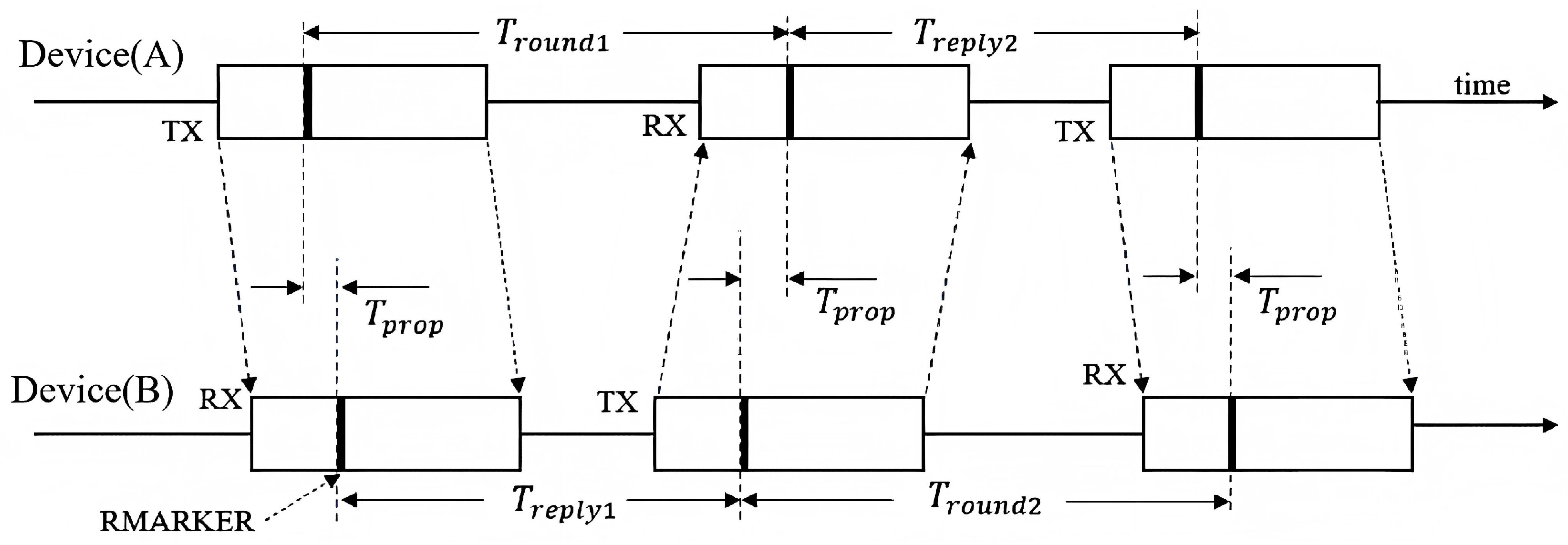
UWB ranging determines the distance between the tag and the base station based on the propagation time of the wireless signal. Electromagnetic waves propagate at approximately the speed of light; therefore, the distance between the tag and the base station can be computed once the one-way propagation time is obtained. In this study, a two-way ranging method was adopted. Devices A and B transmit and receive signals multiple times, while the corresponding timestamps are recorded to reduce the influence of device response delays on the ranging results [24]. Figure 4 illustrates the timing diagram of the UWB two-way ranging process.
As shown in Figure 4, device A first sends a ranging signal to device B. After receiving the signal, device B then returns a response signal to device A after a certain reply time. Subsequently, device A sends another signal, and device B receives such a signal again. Let the two round-trip times be T r o u n d 1 and T r o u n d 2 , and let the two reply times be T r e p l y 1 and T r e p l y 2 . The one-way signal propagation time can be expressed as follows:
T p r o p = T r o u n d 1 T r o u n d 2 T r e p l y 1 T r e p l y 2 T r o u n d 1 + T r o u n d 2 + T r e p l y 1 + T r e p l y 2 ,
where T prop is the one-way propagation time of the UWB signal between the tag and the base station.
The ranging value between the tag and the base station is given by the following:
r = c T prop ,
where r denotes the UWB ranging value, and c represents the propagation speed of the electromagnetic wave.

2.3.2. PDOA Localization Principle

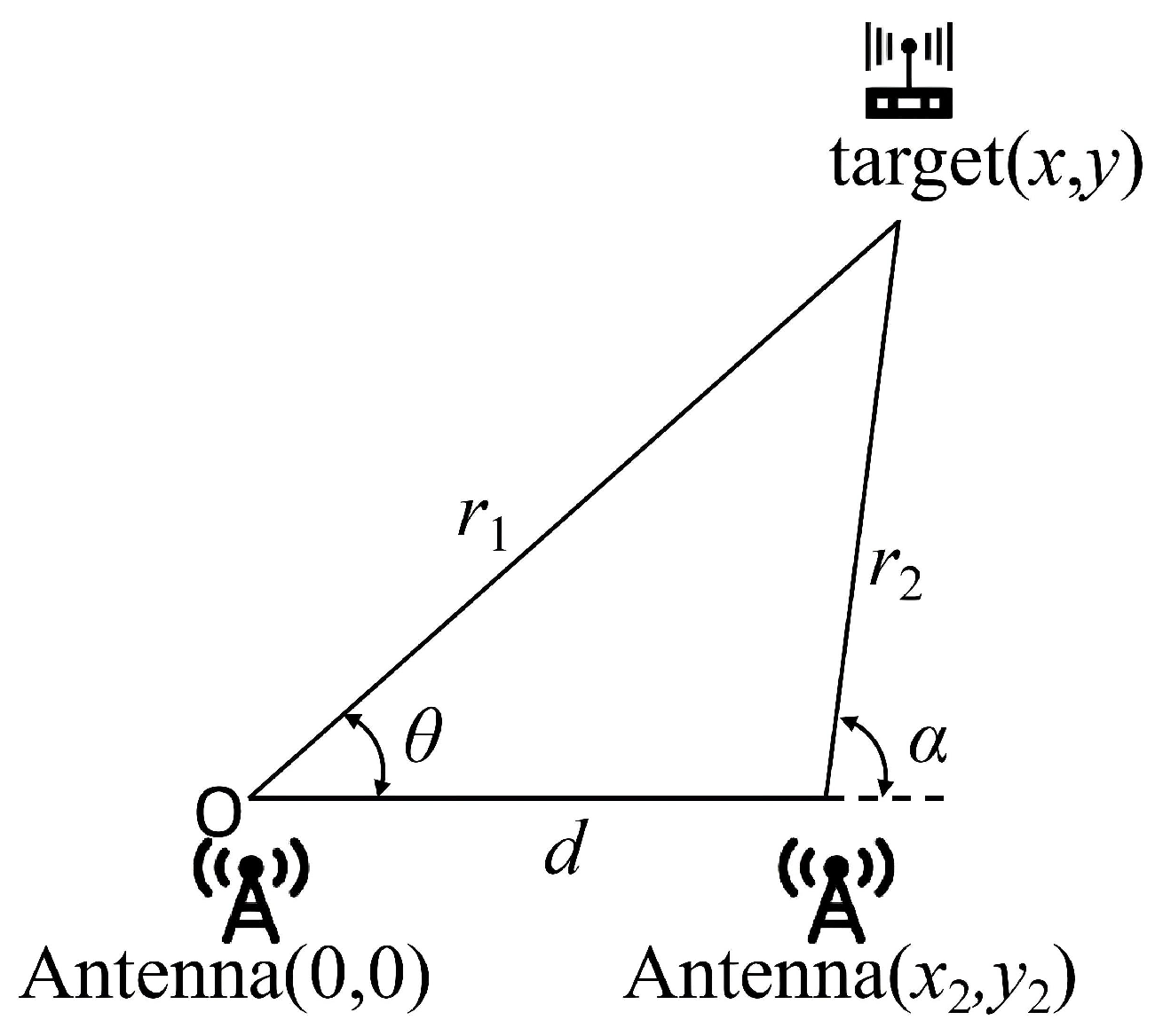
PDOA is an angle-measurement method based on the phase difference in the arriving signal. The UWB base station used in this study is equipped with two receiving antennas, with d representing the distance between the two antennas. When the UWB tag transmits a signal, the propagation paths from the tag to the two receiving antennas differ in length, leading to a phase difference between the two received signals. This phase difference can be converted into a corresponding path difference, from which the theta angle and planar coordinates of the tag relative to the base station can then be calculated [25]. Figure 5 presents the geometric relationship of PDOA localization.
Let the two receiving antennas be Antenna A and Antenna B. d represents the distance between the two antennas, while r1 and r2 represent the distances from the tag to the two antennas. The path difference is defined as follows:
p = r 1 r 2 .
According to the geometric relationship shown in Figure 5, the planar coordinates of the tag in the base station coordinate system can be expressed as follows:
x = r 1 p 2 p d + d 2 y = ± r 1 p 2 1 p d 2 ,
where x and y are the coordinates of the tag relative to the base station coordinate system. The relative azimuth angle of the tag in relation to the base station is calculated using these coordinates:
θ = a r c t a n y x , θ 90 , 90 ,
where θ is the theta angle of the tag relative to the base station.

3. Proposed LSTM-RAEKF Localization Method

3.1. Overall Framework of the Proposed LSTM-RAEKF Localization Method

LSTM networks are effective in extracting temporal dependencies from sequential data, while attention mechanisms can be used to assign different weights to historical features based on their relevance to the current prediction task [26]. These characteristics contribute to the suitability of LSTM-based models for learning nonlinear and time-varying UWB positioning errors from multisource sensor sequences [27].
Kalman filtering provides a recursive framework for integrating motion predictions with noisy observations [28]. However, the use of fixed process- and measurement-noise covariance matrices may degrade filtering performance due to variations in vehicle motion and measurement uncertainty over time. Therefore, adaptive noise-estimation and robust filtering methods have been developed to improve the accuracy and stability of UWB and inertial-sensor fusion [29,30,31].
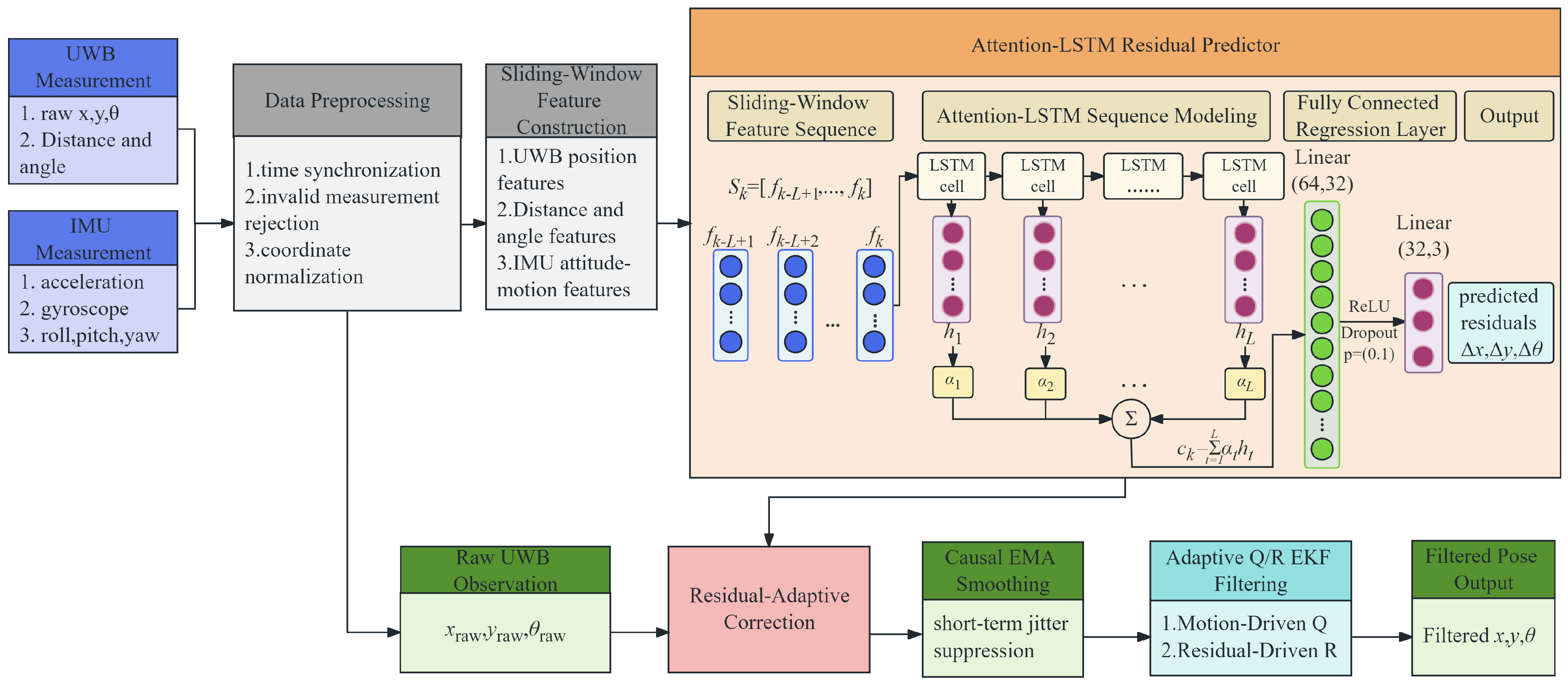
Based on these methods, an LSTM-based residual-adaptive extended Kalman filtering method, referred to as LSTM-RAEKF, was developed, as shown in Figure 6. The synchronized UWB-PDOA and IMU measurements are initially preprocessed and arranged into a time-series feature sequence. The Attention-LSTM network then predicts the residuals of the UWB planar coordinates and the theta angle. These predicted residuals are incorporated through a bounded adaptive gain, followed by causal smoothing and adaptive Q / R EKF processing. The final outputs are the filtered relative coordinates and theta angle.

3.2. Multi-Source Data Input and Preprocessing

The input data comprised synchronized measurements derived from the UWB-PDOA module and the IMU. At sampling time k , the UWB measurement vector was defined as follows:
z k u w b = x k u w b , y k u w b , θ k u w b , r k , α k T ,
where x k u w b and y k u w b are the raw planar coordinates, θ k u w b is the theta angle derived from these coordinates according to Equation (5), r k is the UWB ranging value, and α k is the PDOA angle measurement.
The IMU measurement vector was defined as shown below:
z k i m u = a x , k , a y , k , a z , k , ω x , k , ω y , k , ω z , k , ϕ k , ϑ k , ψ k T ,
where a x , k ,   a y , k , and a z , k are the triaxial accelerations; ω x , k ,   ω y , k , and ω z , k are the triaxial angular velocities; and ϕ k ,   ϑ k , and ψ k denote the roll, pitch, and yaw angles, respectively. These variables represent the instantaneous motion, vibration, and attitude variations in the tracked platform.
Aiming to assess the consistency between the current UWB measurements and the predicted relative motion, the range innovation was calculated as follows:
ε k r = r k r k k 1 p r e d ,
where r k k 1 p r e d is the one-step predicted range obtained from the previous state estimate.
The angle innovation was calculated as shown below:
ε k α = w r a p α k α k k 1 p r e d ,
where α k k 1 p r e d is the one-step predicted angle. The function w r a p ( ) constrains the angular difference to a consistent principal interval, further preventing discontinuities near the angular boundary.
The UWB and IMU variables were then combined to form a 16-dimensional single-frame feature vector:
f k = x k u w b , y k u w b , θ k u w b , r k , α k , ε k r , ε k α , a x , k , a y , k , a z , k , ω x , k , ω y , k , ω z , k , ϕ k , ϑ k , ψ k T .
The selection of the 16-dimensional feature vector was based on the physical characteristics of UWB-PDOA localization errors and the requirements of residual learning. The selected variables encompass four types of information. First, the UWB-PDOA measurements describe the current relative localization state, including position, distance, and angular observations. Second, the IMU-derived variables capture information related to vehicle motion and attitude variation, including acceleration, angular velocity, and attitude angles. Third, the range and angle innovations determine the discrepancies between the current observations and the predicted states, providing additional information related to measurement reliability and error evolution. Overall, the constructed feature vector combines observation information, dynamic motion characteristics, attitude states, and measurement consistency, thereby enabling the Attention-LSTM network to learn the temporal evolution of disturbance-related localization residuals.
Prior to the construction of the temporal input sequence, the synchronized UWB and IMU measurements were preprocessed to remove missing, invalid, or abnormal samples. Coordinate and angular variables were then converted into a unified representation. All input features were standardized using the mean and standard deviation calculated from the training set, applying the same normalization parameters during evaluation. The raw UWB observations were retained in their original physical units for subsequent residual correction and EKF processing.
Finally, the latest L feature vectors were arranged into a sliding-window sequence:
S k = f k L + 1 , f k L + 2 , , f k T .
In this study, the window length L was set to 10. Therefore, each input sequence encompassed the current synchronized feature vector and the preceding nine feature vectors. The sliding window was updated when a new measurement became available. Thus, the residual prediction at time k used only current and historical information, ensuring causal estimation and facilitating online implementation of the proposed method.
The experimental dataset used to develop and evaluate the Attention-LSTM network was collected from multiple UWB/IMU experiments, including fixed-point attitude disturbance, straight-line motion, and turning conditions. A total of 115,000 UWB-PDOA output samples were obtained, comprising 90,000 samples from fixed-point experiments, 15,000 samples from straight-line motion, and 10,000 samples from turning motion. The 90,000 fixed-point samples were evenly distributed among the four disturbance conditions, including static, pitch, roll, and vibration, with 22,500 samples collected under each condition. The dataset was partitioned into training, validation, and testing subsets at approximate ratios of 70%, 15%, and 15%, respectively. To avoid information leakage caused by temporal correlation between adjacent measurements, the partitioning was performed at the level of complete experimental repetitions rather than by randomly splitting individual samples. Experimental repetitions from each disturbance condition were assigned to the three subsets using approximately the same proportions, while all measurements from the same experimental sequence were retained within a single subset. The validation subset was used to monitor model convergence and select the optimal model during training, whereas the testing subset was reserved for final performance evaluation. The corresponding localization residuals between the raw UWB-PDOA observations and the reference poses were used as the learning targets for Attention-LSTM training.

3.3. Attention-LSTM Residual Prediction

Although the UWB-PDOA and IMU sensors operated at output rates of 100 and 200 Hz, respectively, the synchronized measurements were processed at 20 Hz for localization estimation. Therefore, the state prediction interval was set to Δt = 0.05 s.
The sliding-window sequence S k was fed into a two-layer LSTM network to capture the temporal dependencies among UWB observations, platform motion, attitude variation, and positioning errors. The hidden-state dimension of each LSTM layer was set to 64. Rather than relying only on the hidden state at the final time step, the attention mechanism assigns different weights to the hidden states across the sequence, allowing the network to emphasize highly relevant historical features for predicting the current localization residual.
The attention-weighted temporal feature was calculated as follows:
c k = t = 1 L   α t h t ,
where h t denotes the LSTM hidden state at the t -th time step, α t represents the corresponding normalized attention weight, and c k is the temporal context vector generated for the current prediction. The attention weights were calculated using a fully connected scoring layer followed by SoftMax normalization.
The temporal context vector was then mapped to the predicted UWB positioning residuals:
Δ p k p r e d = g F C c k = Δ x k p r e d Δ y k p r e d Δ θ k p r e d ,
where Δ x k pred ,   Δ y k pred , and Δ θ k pred are the predicted residuals of the planar coordinates and theta angle. The regression module comprised a 64-to-32 linear layer, followed by a ReLU activation function, a dropout layer with a probability of 0.1, and a 32-to-3 output layer. Accordingly, the network was designed to estimate the UWB measurement residuals rather than directly predict the final relative pose.
During offline training, the reference residuals were calculated as the differences between the reference poses and the corresponding raw UWB observations. For the theta component, the shortest angular difference was used to avoid discontinuities near the angular boundary. The network parameters were optimized using the mean squared error loss:
L = 1 N k = 1 N   Δ p k p r e d Δ p k r e f 2 2 ,
where N is the number of training samples, while Δ p k ref is the reference residual vector. After training, the predicted residuals were transferred to the residual-adaptive correction module for bounded compensation of the raw UWB observations.
All input features were standardized using the mean and standard deviation calculated from the training set, and the same normalization parameters were applied to the testing set.
During training, the input sequence length was set to L = 10, and the network parameters were optimized by minimizing the residual prediction loss defined in Equation (14). The optimized model was then evaluated on the independent testing dataset. During online inference, each input sequence contained only the current and previous measurements, thereby ensuring that no future information was used.

3.4. Residual-Adaptive Correction and Causal Smoothing

The residuals predicted using the Attention-LSTM network may reveal different reliability levels under different motion conditions. Therefore, a bounded adaptive gain λ k was introduced to control the contribution of the predicted residuals. The gain was determined based on the magnitudes of the predicted planar and angular residual, together with the local motion state. Large predicted residuals increased the correction contribution, whereas rapid changes in displacement or theta variation reduced the gain to minimize the risk of transient overcorrection. The residual-corrected UWB observation was then calculated as follows:
z k c = z k u w b + λ k Δ p k p r e d ,
where z k uwb contains the raw UWB planar coordinates and theta angle, Δ p k pred is the residual predicted by the Attention-LSTM network, and z k c is the corrected observation. The bounded adaptive gain ensures that the predicted residual is used as a correction term rather than directly replacing the UWB measurement. In this study, the initial residual gain was set to λ 0 = 0.50, and the adaptive gain λ k was limited to the range of [0.20, 0.80]. The detailed gain adjustment procedure is presented in Algorithm 1.
Aiming to further suppress short-term fluctuations, a causal exponential moving average was applied to the corrected observations:
z k s = β z k c + ( 1 β ) z k 1 s ,
where z k s is the smoothed observation and β is the smoothing coefficient, which was set to 0.75. The smoothing process uses only the current corrected observation and the previous smoothed result, thereby avoiding the introduction of future information. For the theta component, the shortest angular difference was used to prevent discontinuities near the angular boundary.

3.5. Adaptive Q/R Extended Kalman Filtering

The uncertainty associated with the vehicle motion model and the reliability of UWB observations vary during the motion process. Therefore, using fixed process- and measurement-noise covariance matrices may lead to slow filter responses during rapid motion or excessive fluctuations under unstable measurement conditions. Aiming to improve the adaptability of the filter, Q k and R k were adjusted online as follows:
Q k = η Q , k Q 0 R k = η R , k R 0 ,
where Q 0 and R 0 are the initial process- and measurement-noise covariance matrices, respectively. The scaling factor η Q , k was adjusted based on the local motion intensity, whereas η R , k was adjusted using the discrepancy between the smoothed observation and the raw UWB measurement. Both scaling factors were bounded to prevent abrupt covariance changes. A larger motion intensity increased Q k to improve the response to state variation, while a larger observation discrepancy increased R k to reduce the influence of unreliable measurements. The detailed update procedure is summarized in Algorithm 1.
The relative localization state was defined as follows:
x k = x k , y k , θ k , v x , k , v y , k , ω k T ,
where x k ,   y k , and θ k are the relative planar coordinates and theta angle, v x , k and v y , k are the planar velocities, and ω k is the angular velocity.
Using the smoothed observation z k s , the EKF prediction and measurement-update processes were expressed as follows:
x k k 1 = f x k 1 k 1 P k k 1 = F k P k 1 k 1 F k T + Q k K k = P k k 1 H k T H k P k k 1 H k T + R k 1 x k k = x k k 1 + K k z k s h x k k 1 P k k = I K k H k P k k 1
where x k k 1 and x k k are the prior and posterior state estimates, respectively; P k k 1 and P k k are the corresponding error covariance matrices; f ( ) and h ( ) are the state-transition and observation functions, respectively; F k and H k are their Jacobian matrices; and K k is the Kalman gain.
Before the measurement update, the theta innovation was constrained to the principal angular interval. The adaptive adjustment of Q k and R k allows the EKF to respond rapidly to changes in vehicle motion while reducing its dependence on unstable UWB observations. The posterior state x k k provides the final filtered relative coordinates and theta angle.
The complete online procedure of the proposed LSTM-RAEKF method is summarized in Algorithm 1, which includes feature construction, residual prediction and correction, causal smoothing, adaptive Q/R adjustment, and EKF state estimation.
Algorithm 1: Pseudocode of the proposed LSTM-RAEKF fusion localization method
Input:  z k u w b , z k imu , trained Attention-LSTM model, L , x 0 , P 0 , Q 0 , R 0
Output: Filtered relative pose p f , k = x k k , y k k , θ k k T
1. S
2.for each synchronized sampling time k do
3.   z k u w b , z k i m u P r e p r o c e s s z k u w b , z k imu
4.   ε k r , ε k α I n n o v a t i o n z k u w b
5.   f k S t a n d a r d i z e z k u w b , z k imu , ε k r , ε k α
6.   S k ← UpdateWindow S k 1 , f k , L
7.  if length S k < L then
8.   continue
9.  end if
10.  Attention-LSTM residual prediction:
   h t L S T M S k
   α t ← Attention h t
   c k t = 1 L α t h t
   Δ p k pred ← Regression c k
11.  Residual-adaptive correction and causal smoothing:
   s p , k , s θ , k , s m , k ← ResidualMotionScore Δ p k pred
   λ k c l a m p A d a p t i v e G a i n s p , k , s θ , k , s m , k , λ m i n , λ m a x
   z k c x k u w b , y k u w b , θ k u w b T + λ k Δ p k pred
   z k s β z k c + ( 1 β ) z k 1 s
   θ k s w r a p θ k s
12.  Adaptive Q / R estimation:
   η Q , k MotionScale s m , k
   η R , k ObservationScale z k s , z k uwb
   Q k η Q , k Q 0
   R k η R , k R 0
13.  EKF state estimation:
   x k k 1 , P k k 1 ← EKFPredict x k 1 k 1 , P k 1 k 1 , Q k
   K k P k k 1 H k T H k P k k 1 H k T + R k 1
   x k k , P k k ← EKFUpdate z k s , x k k 1 , P k k 1 , K k
   p f , k x k k , y k k , θ k k T
14.end for
15.return the filtered relative pose sequence
Algorithm 1 summarizes the execution order of the proposed method and illustrates the integration of the data-driven residual predictor with bounded residual correction and adaptive EKF estimation. Table 1 lists the principal implementation parameters.

3.6. Experimental Conditions and Evaluation Metrics

Aiming to evaluate the localization performance of the proposed LSTM-RAEKF method under attitude disturbance conditions, experiments were conducted using the UWB/IMU relative localization test bench described in Section 2.2. The UWB tag was mounted on the servo linear guide, while the UWB base station and IMU were fixed on the six-degree-of-freedom motion platform.
Four experimental conditions were considered: static, pitch disturbance, roll disturbance, and vibration disturbance. The static condition served as the baseline. For the pitch and roll disturbance tests, the maximum inclination angle of the platform was set to 15°, representing the body inclination of a tracked vehicle operating on uneven ground or slopes. The vibration condition was designed to simulate the normal body oscillations experienced during vehicle operation.
The raw UWB-PDOA results and the LSTM-RAEKF results were compared with the reference pose. The planar positioning error at sampling time k was calculated as follows:
e p , k = x k f x k r e f 2 + y k f y k r e f 2 ,
where x k f and y k f are the filtered planar coordinates, while x k r e f and y k r e f are the corresponding reference coordinates.
The theta error was calculated using the shortest angular difference:
e θ , k = w r a p θ k f θ k ref ,
where θ k f is the filtered theta angle, and θ k ref is the reference theta angle.
Overall, the comparison was designed to evaluate the accuracy and robustness of the proposed method under different platform disturbances. By comparing the position and theta errors before and after filtering, the effectiveness of LSTM-RAEKF in suppressing disturbance-induced measurement deviations while preserving the actual relative motion trends can be assessed. The following results further illustrate its performance under static, pitch, roll, and vibration conditions.

4. Results and Discussion

4.1. Effect of Attitude Disturbance on Raw UWB Measurements

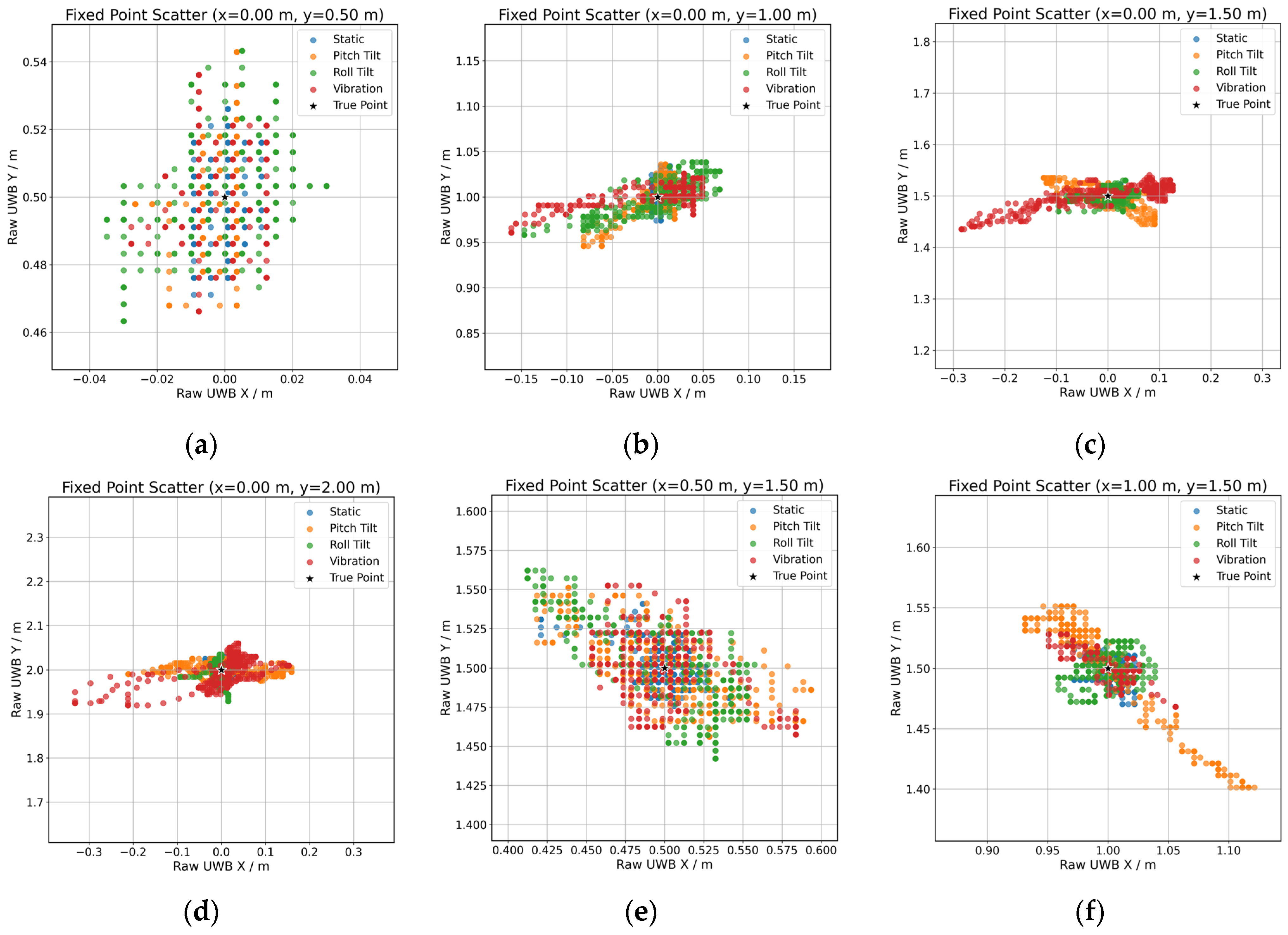
Figure 7 shows the scatter distributions of raw UWB measurements at six fixed target positions under static, pitch, roll, and vibration conditions. Compared with the static condition, attitude disturbances introduce increased dispersion and directional deviation in the measured coordinates. At the short-distance position of (0.00, 0.50) m, the measurement deviations remain relatively small, revealing maximum deviations of approximately 0.04 and 0.05 m in the x- and y-directions, respectively. However, the lateral positioning error becomes pronounced as the target distance increases along the longitudinal direction. At (0.00, 1.00), (0.00, 1.50), and (0.00, 2.00) m, the maximum x-direction deviations increase to approximately 0.16, 0.30, and 0.34 m, respectively, while the y-direction deviations remain within approximately 0.05–0.08 m. These results indicate that attitude variations mainly affect the lateral coordinate estimation, with the magnitude of the resulting error increasing as the relative distance increases.
The disturbance effect also depends on the relative position of the target. At off-axis positions, such as (0.50, 1.50) m and (1.00, 1.50) m, the scatter points exhibit clear directional distributions rather than simple random expansion, with maximum coordinate deviations reaching approximately 0.10–0.12 m. Furthermore, vibration disturbances result in larger dispersion and a noticeable partial offset compared with the static condition. These results demonstrate that raw UWB-PDOA measurements are affected by the combined effects of platform attitude and target geometry, resulting in position-dependent errors. Therefore, incorporating IMU-derived attitude and motion information is necessary for residual compensation and robust relative localization under disturbed conditions.

4.2. Localization Performance Under Different Attitude Disturbances

Aiming to evaluate the robustness of the proposed method, static, pitch, roll, and vibration conditions were considered. The maximum pitch and roll angles were both set to 15°, representing the attitude variation in a tracked vehicle operating on uneven ground or slopes. Periodic excitation was then applied in the vibration test to reproduce the continuous body oscillation generated during vehicle motion. The raw UWB-PDOA measurements were then processed using the proposed LSTM-RAEKF method, including residual prediction, adaptive correction, causal smoothing, and EKF-based fusion.
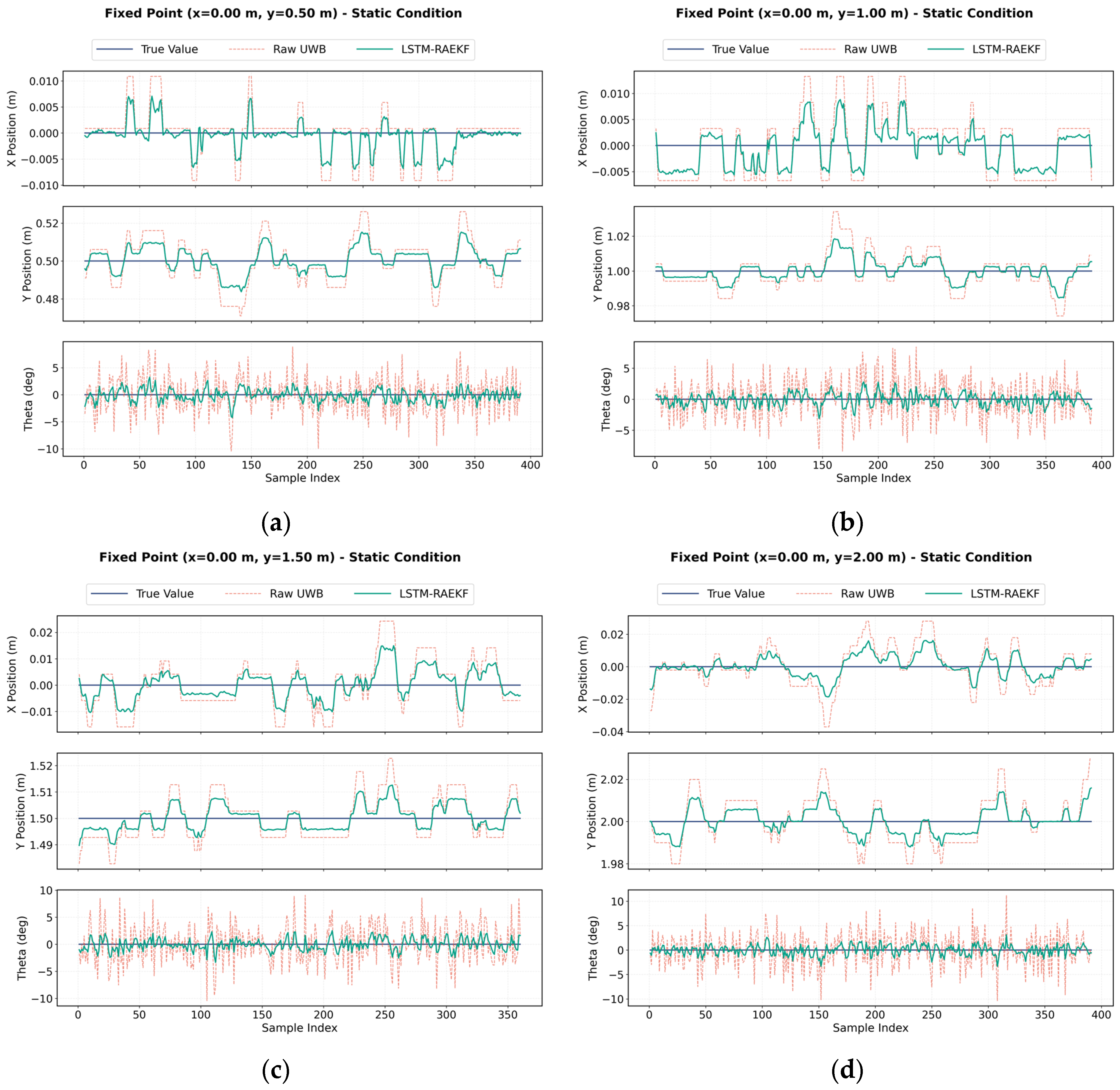
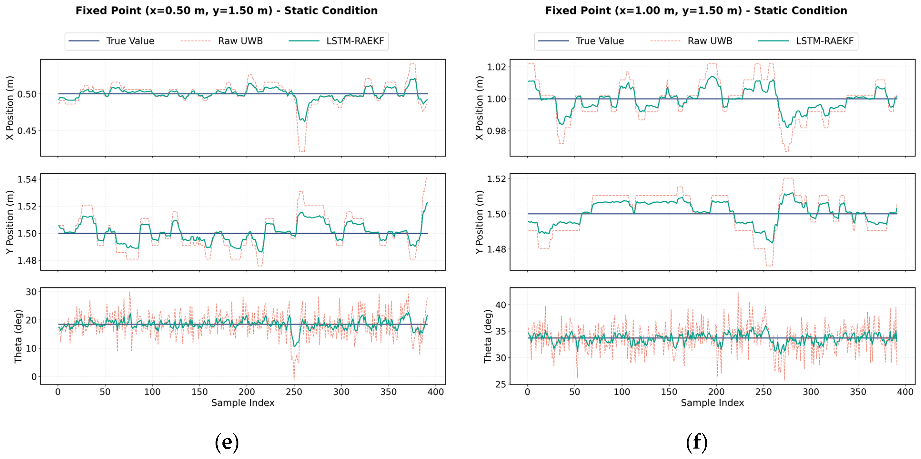
Under the static condition in Figure 8, the raw coordinate errors are mainly distributed within approximately ±0.02–0.03 m, while the theta measurements contain high frequency fluctuations, with several deviations approaching 10°. After filtering, the x and y coordinate errors are more densely distributed around zero, whereas the theta curves become noticeably smoother. This finding indicates that the proposed method can reduce random measurement noise even in the absence of substantial attitude disturbance.
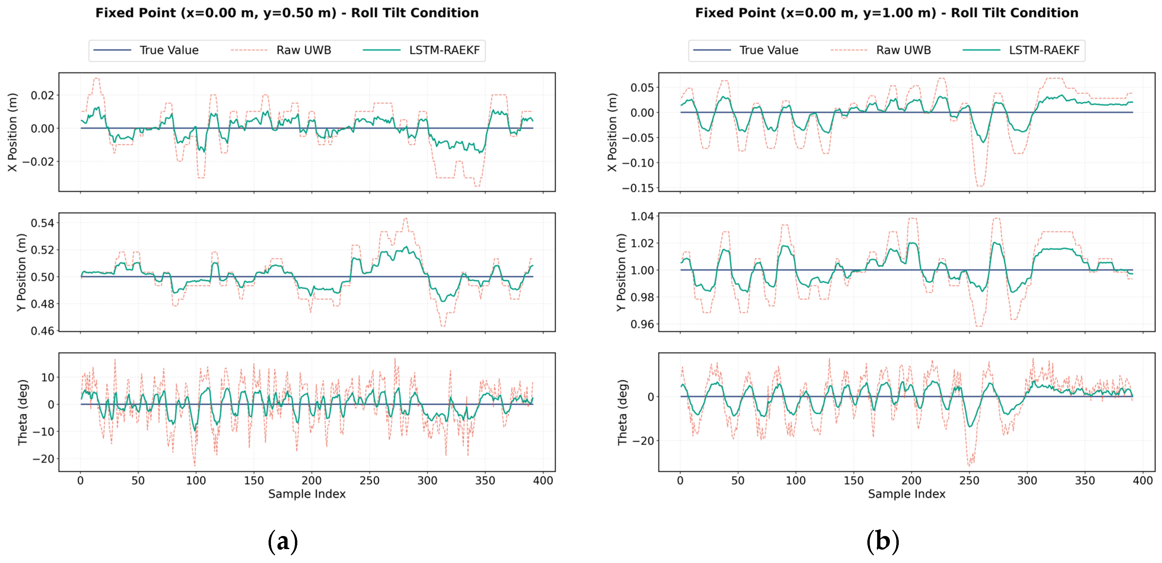
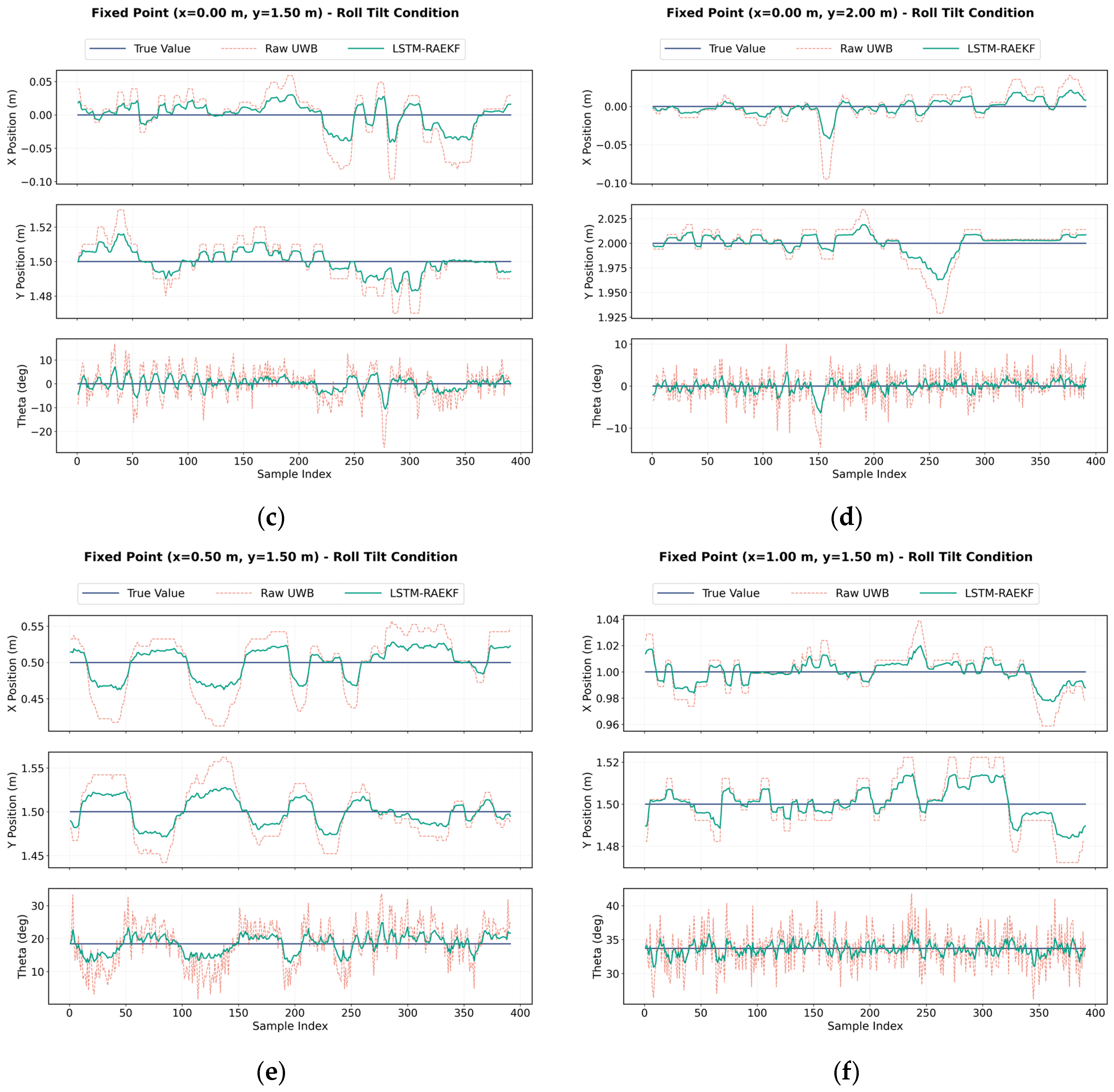
Under the roll-disturbance condition shown in Figure 9, the raw x- and y-coordinate measurements exhibit pronounced periodic deviations, with several local errors exceeding 0.10 m at certain test positions. The theta measurements demonstrate strong fluctuations, with many deviations exceeding 10° and several local peaks reaching approximately 20–30°, particularly at long distances and off-axis positions. After filtering, the coordinate estimates remain closer to the reference values, while the theta fluctuations are substantially reduced and the overall curves become smoother. These results indicate that the proposed method effectively suppresses the periodic position and angular errors induced by roll disturbances, further improving the stability and accuracy of relative localization.
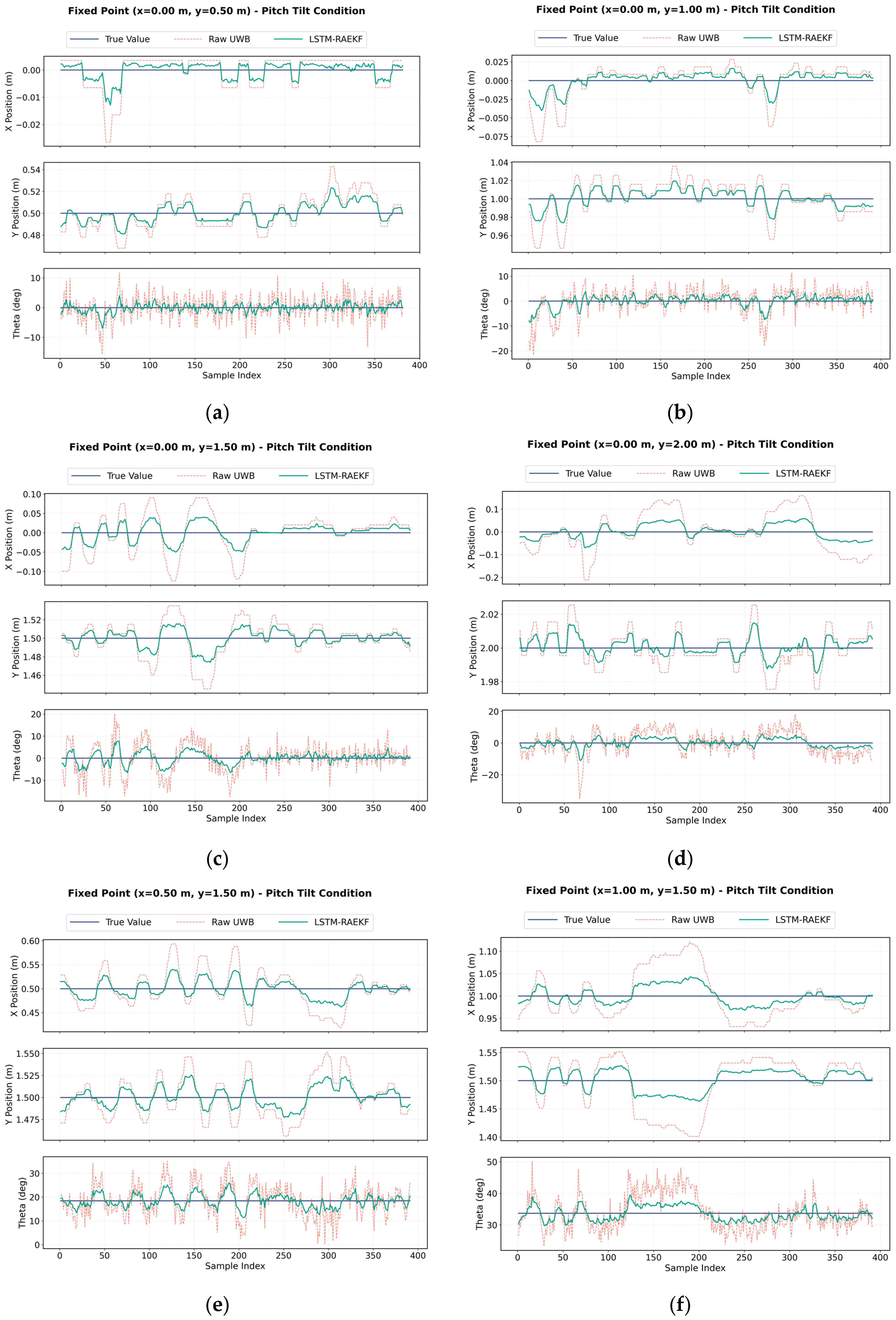
Under the pitch-disturbance condition shown in Figure 10, the raw measurements exhibit more pronounced directional offsets and step-like variations than those observed under roll disturbance. The positioning error becomes highly pronounced as the longitudinal distance increases, indicating that pitch variations have strong effects on range-related coordinate estimation. At several remote target positions, the coordinate deviations reach approximately 0.10–0.15 m. After filtering, these systematic offsets are substantially reduced, and the estimated coordinates remain closer to the reference values during the attitude transition process.
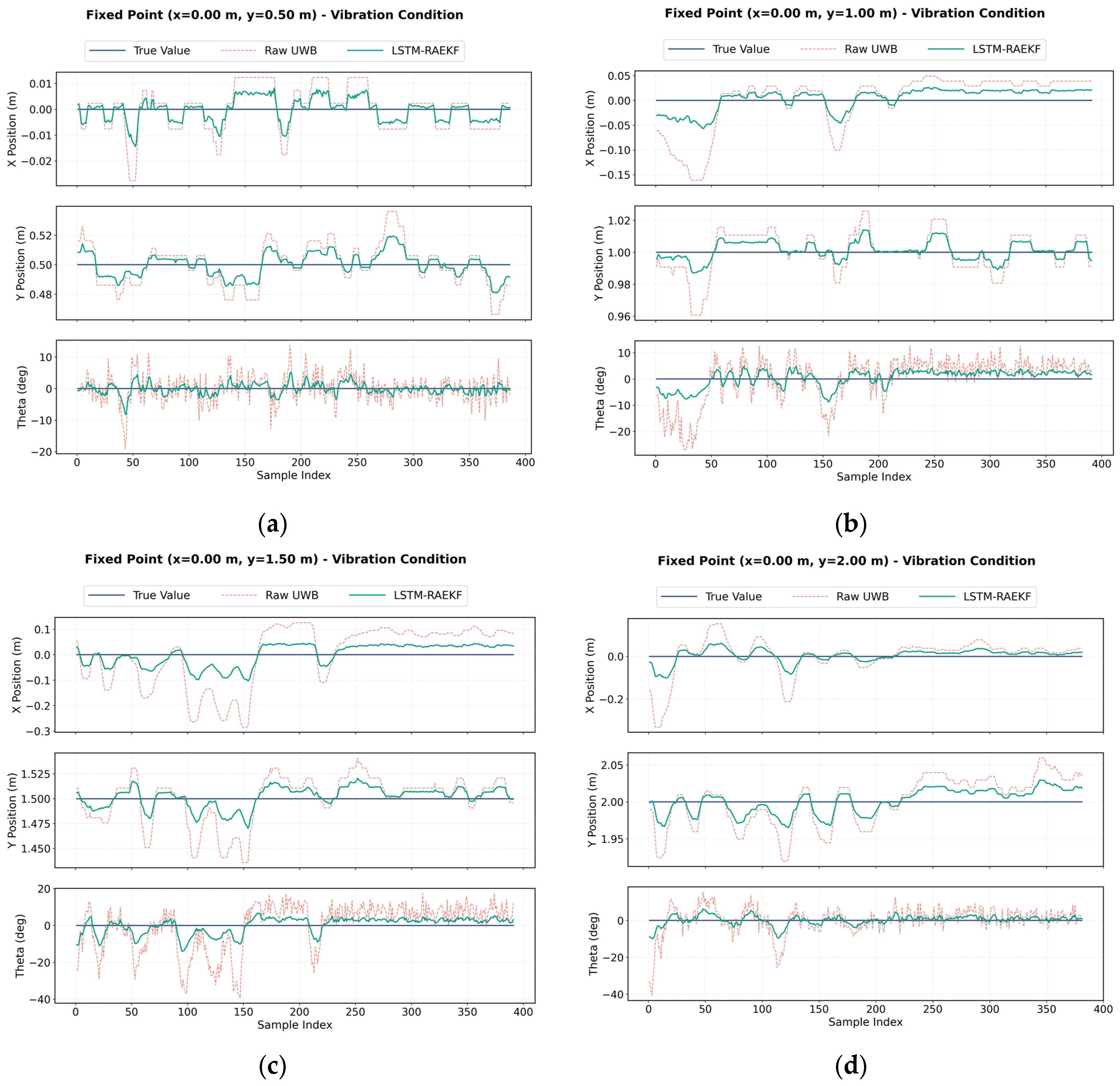
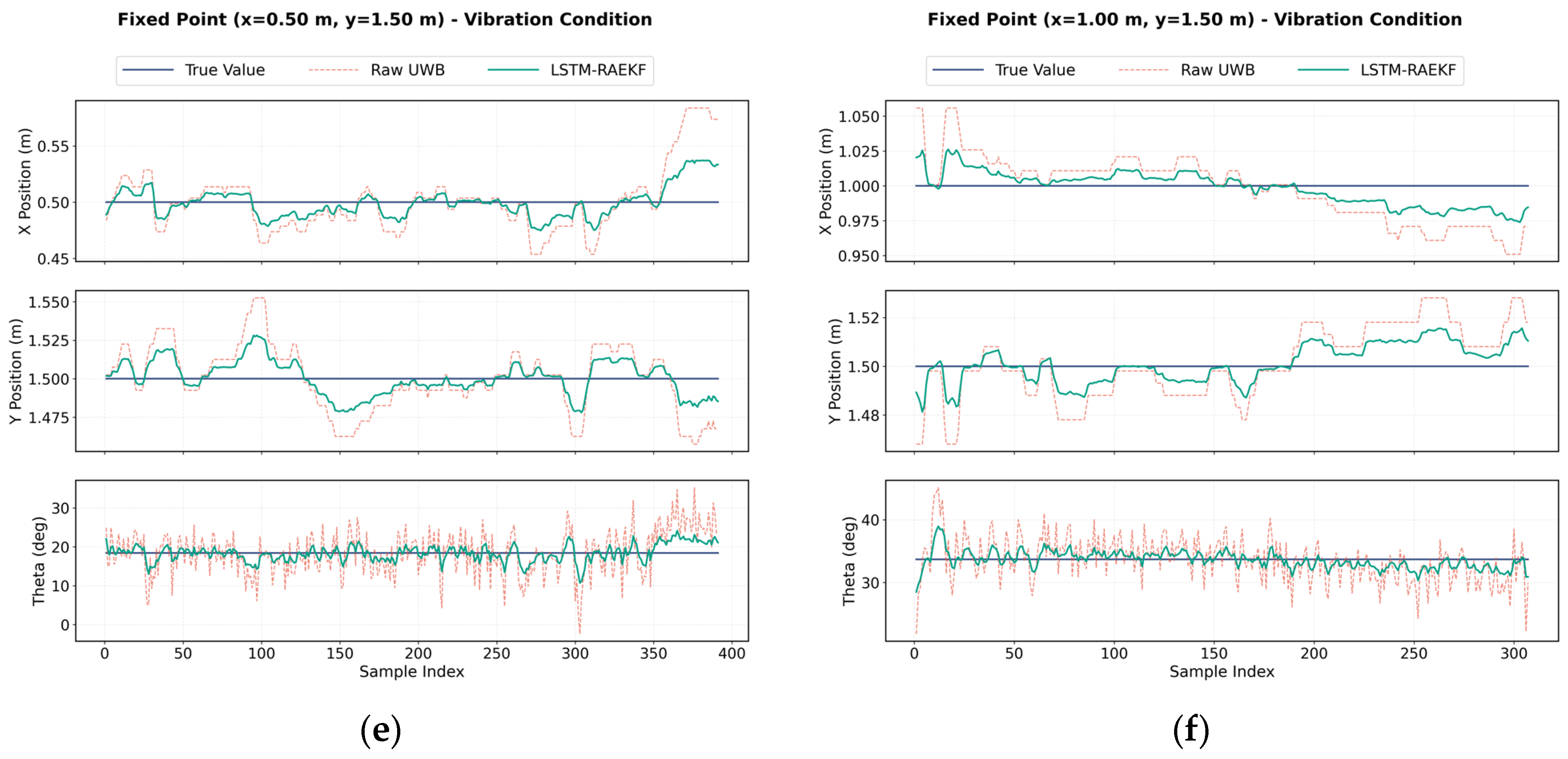
The vibration condition illustrated in Figure 11 is characterized by high-frequency fluctuations and isolated large outliers. Compared with the other experimental conditions, the raw measurements exhibit a wider error distribution, with the x -coordinate deviation reaching 0.30 m at some long-distance positions. The theta measurements also contain intermittent large peaks. After filtering, these abnormal peaks are markedly weakened, resulting in continuous coordinate and angular curves. This finding demonstrates that the proposed method is effective not only in mitigating slowly varying attitude-induced errors but also in suppressing transient disturbances caused by vehicle-body vibration. The quantitative changes in RMSE, MAE, and maximum error are analyzed in the following section.
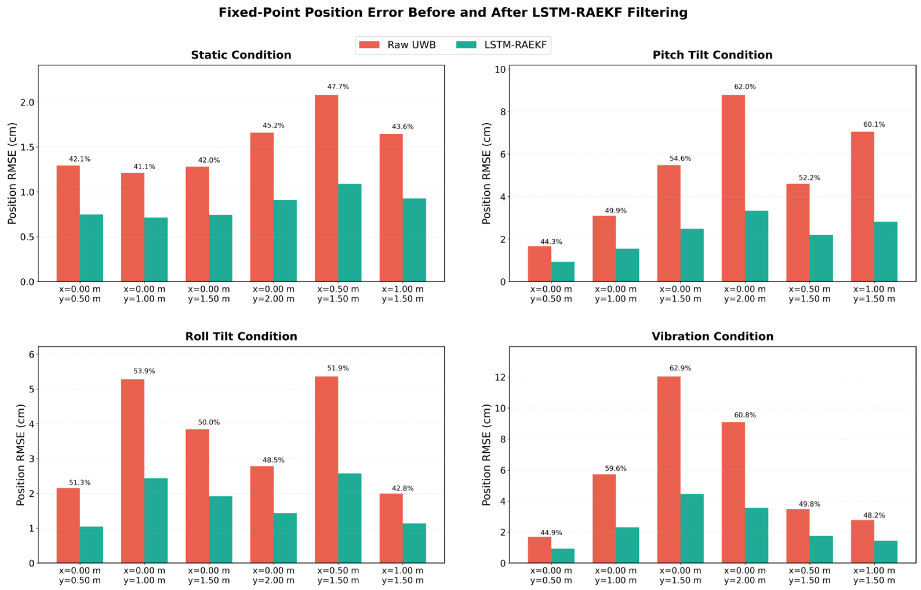
Figure 12 compares the planar position RMSE before and after LSTM-RAEKF filtering at six fixed points under static, pitch-tilt, roll-tilt, and vibration conditions. The percentages shown above the bars indicate the relative reduction in RMSE compared with the raw UWB-PDOA measurements. As shown in Figure 12, the proposed method consistently reduces the planar position error at all test points, achieving RMSE reductions of approximately 35–63%. The improvement is particularly evident under pitch-tilt and vibration conditions, indicating that LSTM-RAEKF effectively suppresses position fluctuations attributed to attitude variations and mechanical vibration. Despite variations in reduction among different fixed points, the filtered RMSE results remain consistently lower than those of the raw measurements, demonstrating stable correction performance across different relative positions and disturbance conditions.
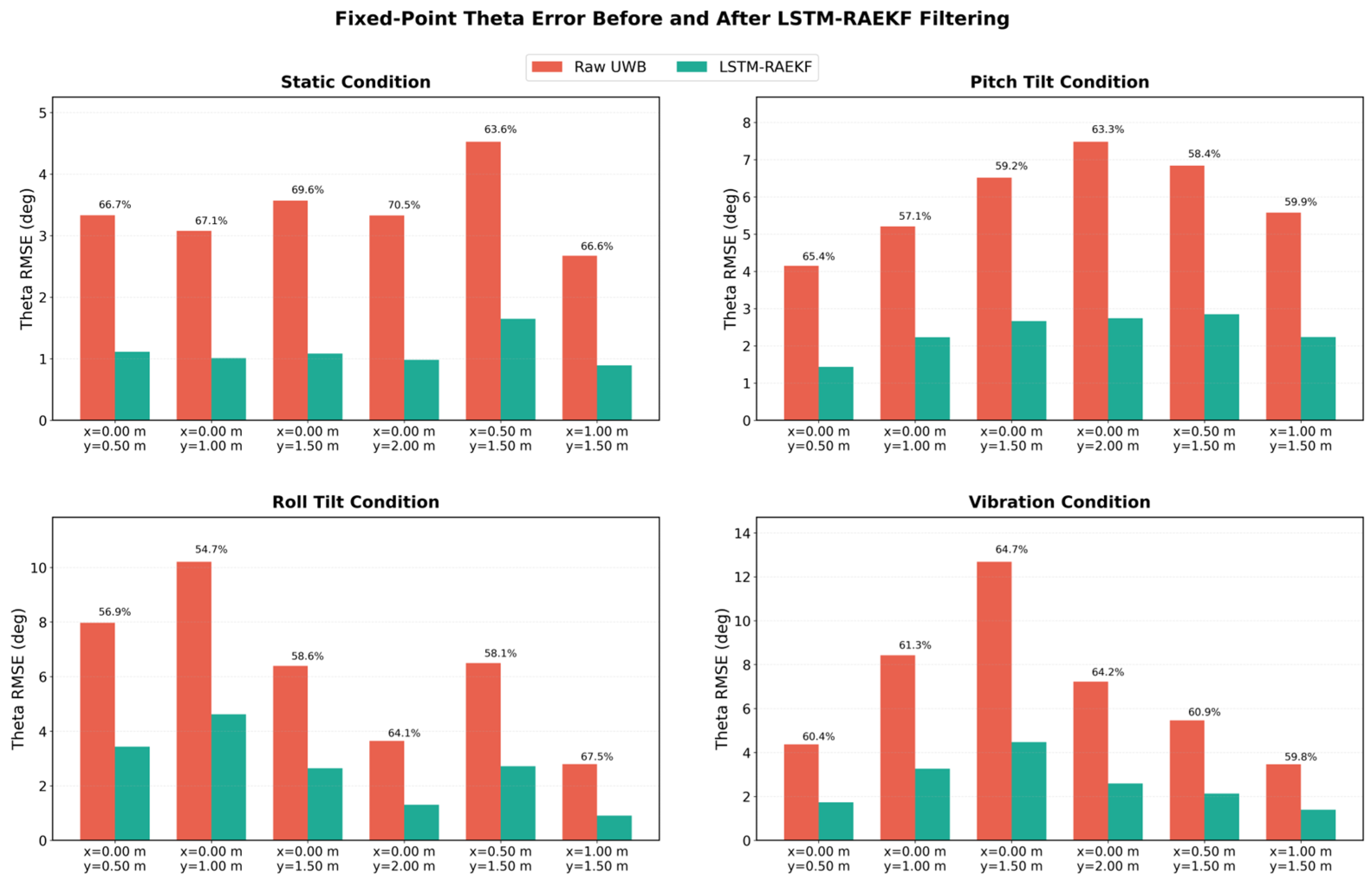
Figure 13 shows that the proposed method substantially improved the theta estimation accuracy under all test conditions. Compared with raw UWB measurements, the theta RMSE was reduced by approximately 54.7–70.8%. The improvement was consistently observed under static, pitch-tilt, roll-tilt, and vibration conditions, demonstrating that the proposed method effectively suppresses angular deviations caused by platform attitude variations and dynamic disturbances. Overall, these results confirm that LSTM-RAEKF provides effective correction of theta errors while maintaining stable estimation performance across different disturbance conditions.

4.3. Trajectory-Level Localization Performance Under Base Station Attitude Disturbance

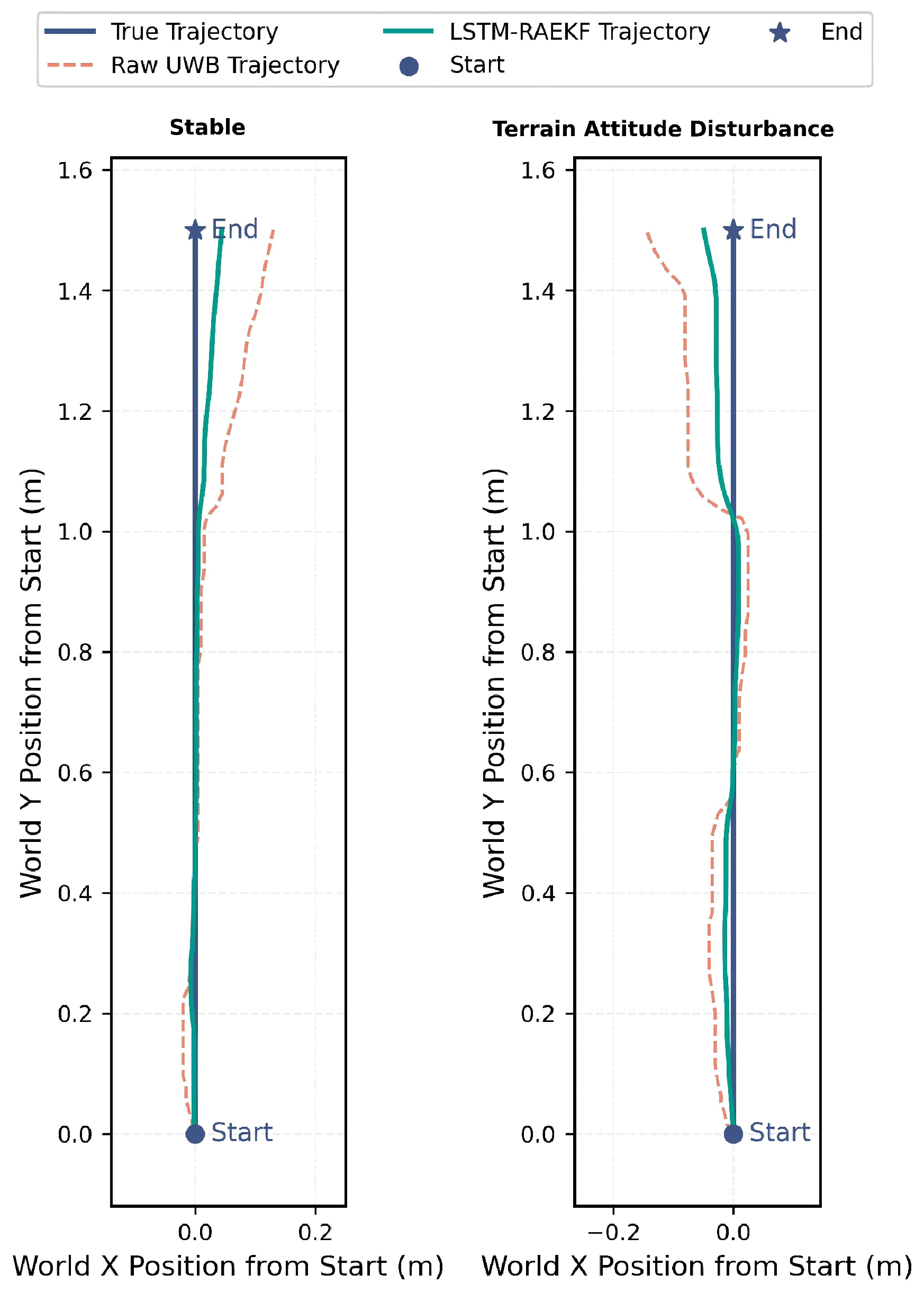
Aiming to further assess localization performance during continuous tag motion, trajectory experiments were performed under stable and attitude-disturbance conditions. In these experiments, the UWB-PDOA base station was fixed at a predefined position, while only its attitude was varied to facilitate simulations of pitch, roll, and vibration disturbances caused by uneven agricultural terrain. Meanwhile, the UWB tag was moved along predefined longitudinal and lateral trajectories to generate the reference paths. Therefore, the deviations observed in the raw UWB-PDOA trajectories were mainly attributed to attitude-induced measurement disturbances rather than actual displacement of the base station.
Figure 14 illustrates the longitudinal trajectory results. Under stable conditions, the raw UWB-PDOA measurements generally followed the reference trajectory but exhibited local fluctuations, with a maximum deviation of approximately 5–7 cm. After LSTM-RAEKF filtering, the estimated trajectory remained closer to the reference path, reducing the maximum deviation to approximately 2 cm. Under terrain-induced attitude disturbances, the raw trajectory exhibited greater lateral fluctuations, particularly during the middle and final stages of motion, with a maximum deviation of approximately 8 cm. In contrast, the LSTM-RAEKF trajectory maintained good consistency with the reference trajectory without substantial distortion, demonstrating the effectiveness of the proposed method in compensating for attitude-induced localization errors.
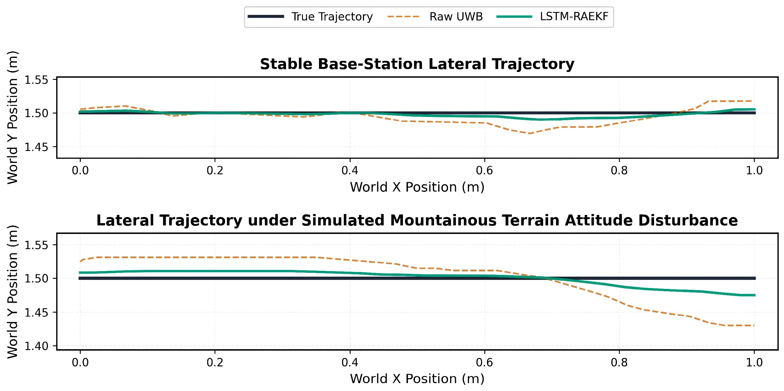
Figure 15 shows the results for the lateral motion of the tag, where the reference lateral position was maintained at approximately 1.50 m, while the tag moved from 0 to 1.0 m in the longitudinal direction. Under stable conditions, the raw measurements were mainly distributed between approximately 1.48 and 1.52 m, whereas the LSTM-RAEKF trajectory remained closer to the reference value of 1.50 m. Under simulated terrain-induced attitude disturbance, the raw trajectory gradually drifted during the second half of the motion, reaching approximately 1.43 m at the endpoint and resulting in an error of approximately 7 cm. After filtering, the endpoint increased to approximately 1.47 m, reducing the residual error to approximately 3 cm.
Overall, the proposed method effectively reduced local fluctuations and accumulated lateral drift caused by base station attitude disturbances, thereby improving trajectory continuity and the robustness of relative localization for vehicle-following applications on uneven terrain.

4.4. Performance Comparison with Baseline Localization Methods

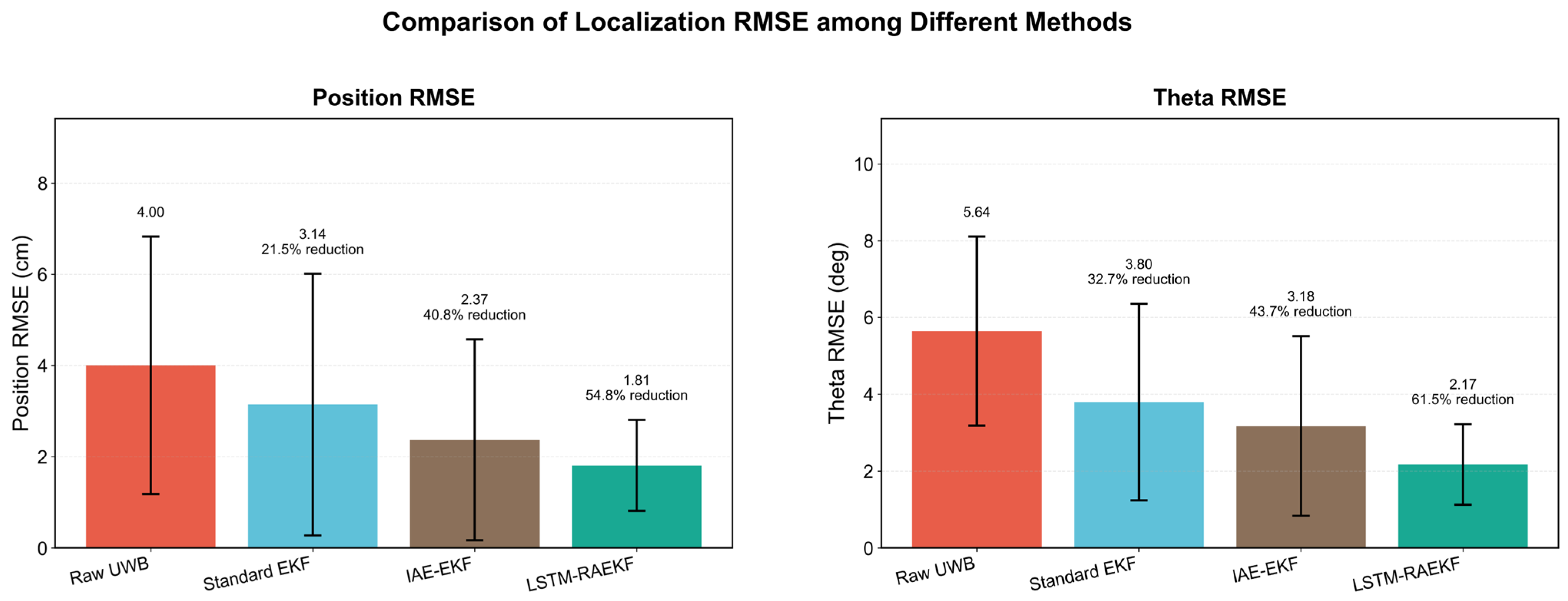
Aiming to evaluate the relative performance of the proposed method, LSTM-RAEKF was compared with raw UWB-PDOA measurements, the standard EKF, and the innovation-based adaptive estimation extended Kalman filter (IAE-EKF) using the combined results from all experimental conditions. The IAE-EKF adaptively adjusts the filter parameters according to the measurement innovation, making it a representative adaptive filtering method for comparison. As shown in Figure 16, the raw UWB measurements yielded a position RMSE of 4.00 cm and a theta RMSE of 5.64°. The standard EKF achieved error reductions of 3.14 cm and 3.80°, corresponding to reductions of 21.5% and 32.7%, respectively. This result confirms that conventional state estimation can partially suppress the random fluctuation in the UWB measurements. The IAE-EKF further decreased the position RMSE to 2.37 cm and the theta RMSE to 3.18°, yielding reductions of 40.8% and 43.7% relative to the raw measurements. This finding demonstrates the effectiveness of adapting the filtering process to changes in measurement reliability.
Among the four methods, LSTM-RAEKF achieved the best overall localization performance. Its position RMSE was reduced to 1.81 cm, indicating reductions of 42.4% and 23.6% compared with the standard EKF and the IAE-EKF, respectively. The corresponding theta RMSE was 2.17°, which was 42.9% and 31.8% lower than that of the standard EKF and IAE-EKF, respectively. Compared with the raw UWB measurements, the proposed method reduced the position and theta RMSEs by 54.8% and 61.5%, respectively. These results indicate that combining temporal residual prediction with adaptive filtering provides more effective correction than either conventional EKF filtering or innovation-based adaptive estimation alone.
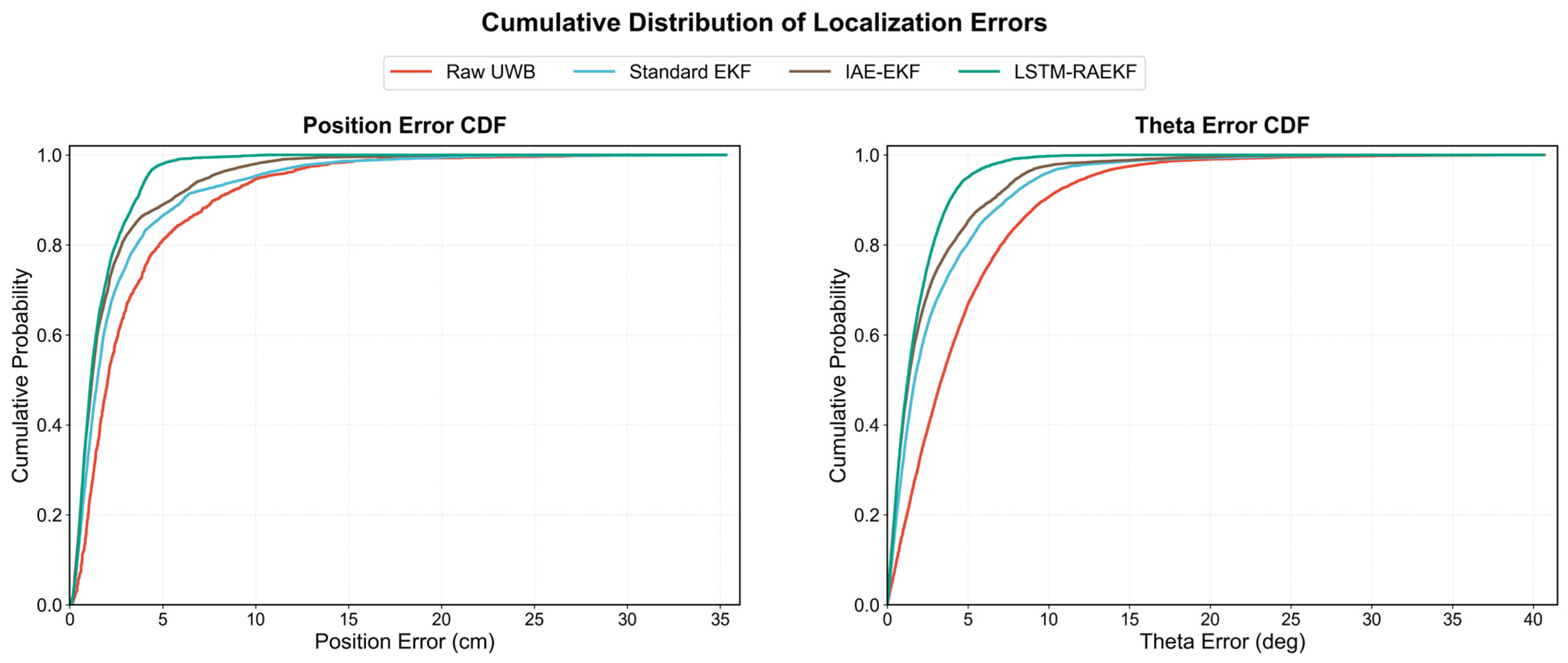
The cumulative error distributions presented in Figure 17 further confirm the performance differences among the compared methods. For position and theta errors, the LSTM-RAEKF curves are located furthest to the left and increase more rapidly, indicating that a larger proportion of its estimates fall within smaller error thresholds. The IAE-EKF generally outperformed the standard EKF, whereas the raw UWB measurements exhibited the slowest cumulative increase and the longest error tails. This ranking is consistent with the RMSE results, revealing that LSTM-RAEKF not only reduces the overall error level but also suppresses large instantaneous errors, thereby providing highly stable relative localization under attitude disturbances and vibration conditions.

4.5. Training Convergence of the Attention-LSTM Model

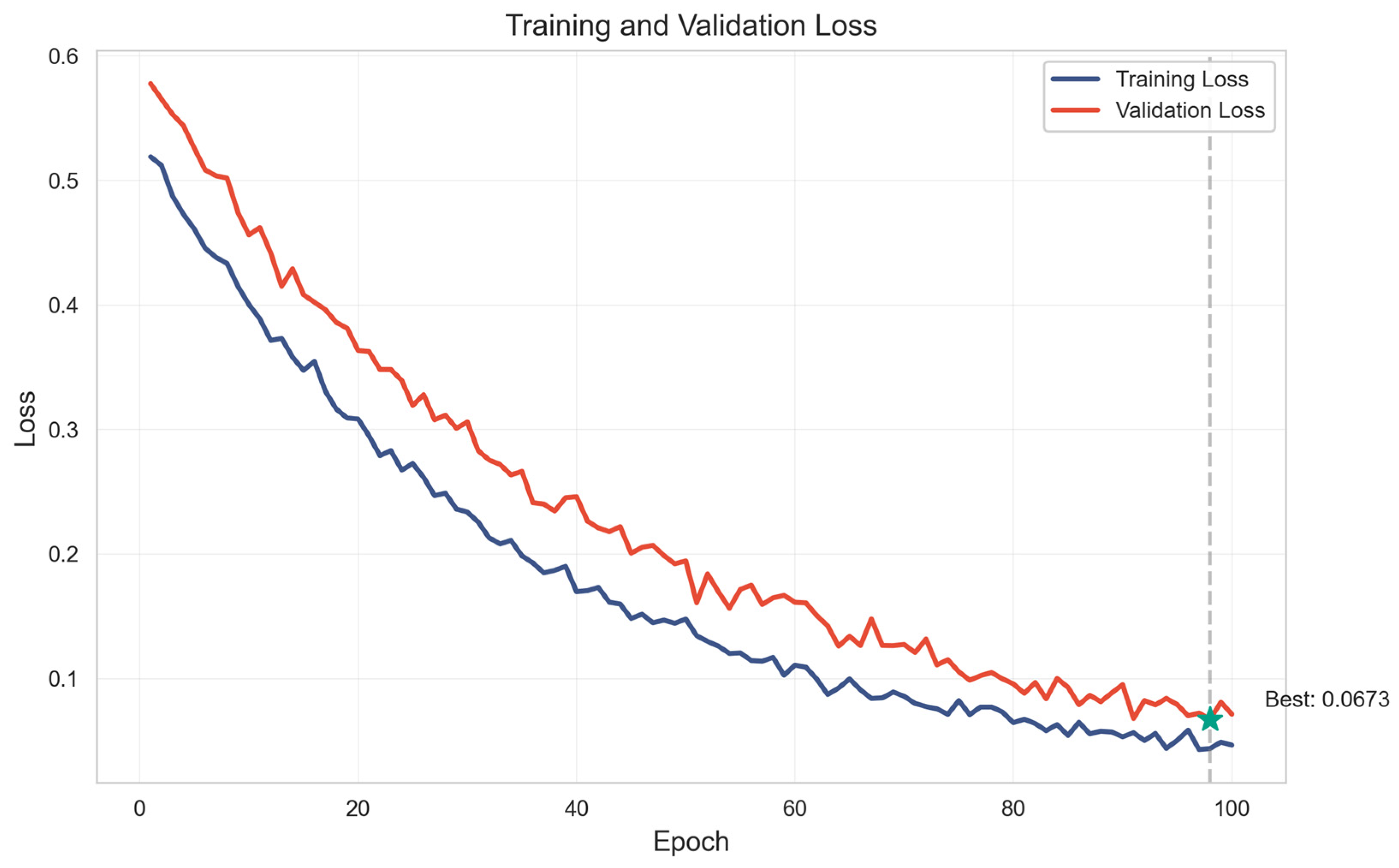
As shown in Figure 18, the convergence behavior of the Attention-LSTM residual prediction model was evaluated using the training and validation loss curves. The validation data were obtained from the independent validation subset described in Section 3.2, which accounted for approximately 15% of the experimental dataset and contained complete experimental sequences that were not included in the training or testing subsets.
Both losses continuously decreased as the number of training epochs increased. The training loss decreased from approximately 0.51 to below 0.05, while the validation loss showed a similar downward trend, reaching a minimum value of 0.0673 near the end of training. Although minimal fluctuations were observed in the validation curve during the later stages of training, no evident divergence was observed between the training and validation losses. These results indicate that the model achieved stable convergence and maintained satisfactory generalization performance, establishing a reliable basis for subsequent online residual correction within the LSTM-RAEKF framework.

4.6. Ablation Study

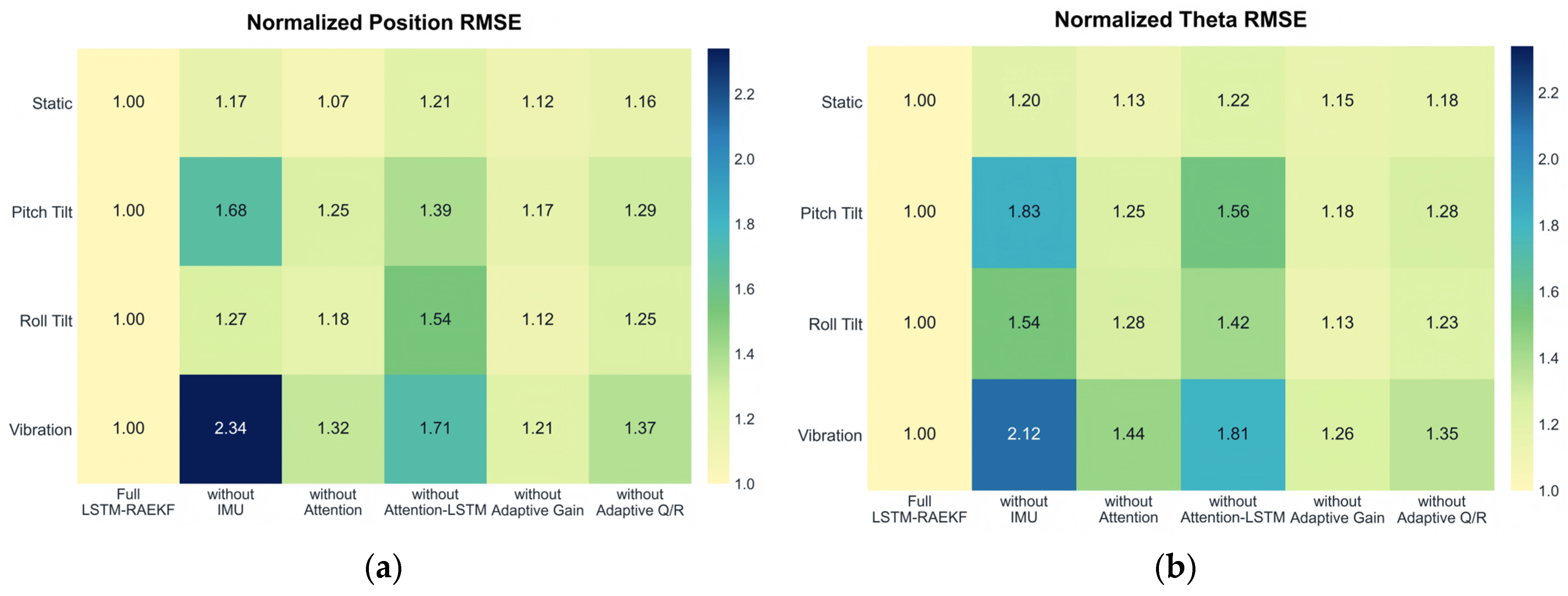
Aiming to evaluate the contributions of the main components of the proposed LSTM-RAEKF method, ablation experiments were conducted under static, pitch-tilt, roll-tilt, and vibration conditions. The complete model was used as the reference, with its position and heading-angle RMSE normalized to 1.00. The IMU input, attention mechanism, complete Attention-LSTM residual prediction module, adaptive residual gain, and adaptive Q/R adjustment were removed individually. Figure 19 illustrates the normalized localization errors.
The residual prediction module also made substantial contributions to localization accuracy. The removal of the complete Attention-LSTM residual prediction module increased normalized position RMSE by 1.39, 1.54, and 1.71 under pitch-tilt, roll-tilt, and vibration conditions, respectively, while the corresponding theta RMSE increased to 1.56, 1.42, and 1.81, respectively. Conversely, removing only the attention mechanism resulted in smaller performance degradation, with the normalized position RMSE ranging from 1.18 to 1.32 and the theta RMSE from 1.25 to 1.44 under dynamic disturbances. These results indicate that temporal residual prediction provides the primary error-compensation capability, while the attention mechanism further enhances the extraction of disturbance-related features.
The ablation results demonstrate that all investigated components contributed to the overall localization performance, with their effects becoming more evident under dynamic disturbances. Among these components, removing the IMU information resulted in the largest overall degradation in performance. Under vibration disturbance, the normalized position and theta RMSEs increased to 2.34 and 2.12, respectively, while under pitch disturbance, they increased to 1.68 and 1.83, respectively. Performance degradation was also observed after removing the Attention-LSTM residual prediction, adaptive residual gain, and adaptive Q/R adjustment, confirming the joint contribution of these modules to improved localization accuracy and robustness against disturbances.

5. Conclusions

This study investigated UWB-PDOA relative localization under platform attitude disturbances and introduced an LSTM-RAEKF-based fusion localization method. The main conclusions are as follows:
(1)
Test-bench experiments showed that pitch, roll, and vibration disturbances adversely affected UWB-PDOA measurements, resulting in fluctuations and position-dependent deviations. Under the tested fixed-point conditions, compared with raw UWB-PDOA measurements, the proposed method reduced the planar position RMSE and the theta RMSE by 35.0–62.9% and 54.7–70.8%, respectively.
(2)
Across all experimental conditions, compared with raw UWB-PDOA measurements. LSTM-RAEKF achieved a position RMSE of 1.81 cm and a theta RMSE of 2.17°, representing reductions of 54.8% and 61.5%, respectively. Compared with the standard EKF, LSTM-RAEKF reduced the position and theta RMSEs by 42.4% and 42.9%, respectively. Considering the IAE-EKF, the corresponding reductions were 23.6% and 31.8%. Ablation experiments further revealed performance degradation after removal of the IMU input, Attention-LSTM residual prediction, adaptive residual gain, or adaptive Q/R adjustment.
(3)
The proposed method provides an enhanced relative localization approach for tracked vehicle following under attitude disturbances. However, the present study was conducted on a controlled test bench and did not involve complete vehicle-following control or long-term field operation. Future work will integrate the proposed LSTM-RAEKF framework with tracked vehicle motion models considering slip and conduct real-vehicle following experiments in hilly and mountainous agricultural environments. Additional environmental factors, including vegetation occlusion, multipath effects, and dynamic obstacles, will also be considered to further improve the robustness of the localization system for practical agricultural applications.

Author Contributions

Conceptualization, D.L. and H.W.; methodology, H.W. and D.L.; software, H.W. validation, H.W., W.X. and Y.Z.; formal analysis, H.W.; investigation, H.W., W.X. and Y.Z.; data curation, H.W.; visualization, H.W.; resources, W.W., K.C. and M.X.; writing—original draft preparation, H.W.; writing—review and editing, D.L., W.X., H.Z., W.W., K.C. and M.X.; supervision, D.L., K.C. and M.X.; project administration, K.C. and M.X.; funding acquisition, W.W., K.C. and M.X. All authors have read and agreed to the published version of the manuscript.

Funding

This research was funded by the National Key R&D Program of China (grant number: 2022YFD2001805), Natural Science Foundation of Jiangsu Province (BK20251524), Zhenjiang City’s “1 + 1 + N” New Agricultural Technology Extension Project (ZJNJ [2024]03), Jiangsu Province Graduate Research Practice Innovation Program (26CXJH1590).

Institutional Review Board Statement

Not applicable.

Data Availability Statement

The original contributions presented in this study are included in the article. Further inquiries can be directed to the corresponding authors.

Acknowledgments

We sincerely acknowledge the financial support from the aforementioned funding agencies. We also thank the anonymous reviewers for providing critical comments and suggestions that improved the manuscript.

Conflicts of Interest

The authors declare no conflicts of interest.

References

  1. Xiao, R.H.; Ma, X.; Li, H.W.; Cao, X.L.; Wei, Y.H.; Wang, C.E.; Zhao, X. Design and Experiment of Agricultural Machinery Auxiliary Navigation System Based on UWB Positioning. J. South China Agric. Univ. 2022, 43, 116–123. [Google Scholar] [CrossRef]
  2. Xie, B.B.; Liu, J.Z.; Cai, L.J.; Xu, Z.H.; Hou, G.L.; Wang, J.; Li, Y.X. Design of the UWB Navigation System for Tracked Agricultural Machinery in Small Land and Analysis of Base Station Layout. Trans. Chin. Soc. Agric. Eng. 2022, 38, 48–58. [Google Scholar] [CrossRef]
  3. Yao, L.J.; Hu, D.; Zhao, C.J.; Yang, Z.D.; Zhang, Z. Wireless Positioning and Path Tracking for a Mobile Platform in Greenhouse. Int. J. Agric. Biol. Eng. 2021, 14, 216–223. [Google Scholar] [CrossRef] [Scilit]
  4. Heydariaan, M.; Dabirian, H.; Gnawali, O. AnguLoc: Concurrent Angle of Arrival Estimation for Indoor Localization with UWB Radios. In Proceedings of the 2020 16th International Conference on Distributed Computing in Sensor Systems, Marina del Rey, CA, USA, 25–27 May 2020; pp. 112–119. [Google Scholar]
  5. Bae, K.; Son, Y.; Song, Y.-E.; Jung, H. Component-Wise Error Correction Method for UWB-Based Localization in Target-Following Mobile Robot. Sensors 2022, 22, 1180. [Google Scholar] [CrossRef] [Scilit] [PubMed]
  6. Brunacci, V.; De Angelis, A.; Costante, G.; Carbone, P. Development and Analysis of a UWB Relative Localization System. IEEE Trans. Instrum. Meas. 2023, 72, 8505713. [Google Scholar] [CrossRef] [Scilit]
  7. Ferrero-Guillén, R.; Díez-González, J.; Martínez-Gutiérrez, A.; Villoria-Ugidos, J.; Moreira, A.; Perez, H. On the Influence of Motion in UWB Localization Methods: A Comparative Analysis in Industrial Scenarios. In Soft Computing Models in Industrial and Environmental Applications; Springer: Cham, Switzerland, 2026; pp. 650–661. [Google Scholar] [CrossRef] [Scilit]
  8. Cao, B.; Yu, Z.; Li, M.; Zhang, C.; Xu, B. A Novel Method for Enhanced Ultra-Wideband Positioning Accuracy in GPS-Denied Environments. Adv. Eng. Inform. 2026, 74, 104767. [Google Scholar] [CrossRef] [Scilit]
  9. Liu, T.X.; Li, B.F.; Yang, L. Phase Center Offset Calibration and Multipoint Time Latency Determination for UWB Location. IEEE Internet Things J. 2022, 9, 17536–17550. [Google Scholar] [CrossRef] [Scilit]
  10. Guo, Y.J.; Li, W.H.; Yang, G.; Jiao, Z.H.; Yan, J.C. Combining Dilution of Precision and Kalman Filtering for UWB Positioning in a Narrow Space. Remote Sens. 2022, 14, 5409. [Google Scholar] [CrossRef] [Scilit]
  11. He, Z.; Tang, X.; Li, M.; Zhang, F. Enhanced Indoor Mobile Robot Localization via Lie-Group IMU–UWB Fusion and Dual-Stage Kalman Filtering. Sensors 2026, 26, 2686. [Google Scholar] [CrossRef] [Scilit] [PubMed]
  12. Osman, A.; Shamsfakhr, F.; Vecchio, M.; Antonelli, F. Adaptive GNSS–UWB Sensor Fusion for Reliable Localization in Precision Agriculture. Smart Agric. Technol. 2026, 13, 101846. [Google Scholar] [CrossRef] [Scilit]
  13. Wei, M.; Liu, L.; Li, S.; Wang, D.; Tang, S. UWB/IMU Integrated Positioning Technology with NLOS Mitigation: An Improved LSSVM and AEKF Fusion Strategy. IEEE Trans. Instrum. Meas. 2026, 75, 9503514. [Google Scholar] [CrossRef] [Scilit]
  14. Gao, H.K.; Li, X.; Song, X. A Fusion Strategy for Vehicle Positioning at Intersections Utilizing UWB and Onboard Sensors. Sensors 2024, 24, 476. [Google Scholar] [CrossRef] [Scilit] [PubMed]
  15. Sun, M.X.; Gao, Y.L.; Jiao, Z.Q.; Xu, Y.; Zhuang, Y.; Qian, P.J. R-T-S Assisted Kalman Filtering for Robot Localization Using UWB Measurement. Mob. Netw. Appl. 2024, 29, 1089–1098. [Google Scholar] [CrossRef] [Scilit]
  16. Xie, K.T.; Zhang, Z.G. High Precision UWB Localization Method for Agricultural Machinery in Unstructured Field Environment. Measurement 2025, 254, 117941. [Google Scholar] [CrossRef] [Scilit]
  17. Hochreiter, S.; Schmidhuber, J. Long Short-Term Memory. Neural Comput. 1997, 9, 1735–1780. [Google Scholar] [CrossRef] [Scilit] [PubMed]
  18. Poulose, A.; Han, D.S. UWB Indoor Localization Using Deep Learning LSTM Networks. Appl. Sci. 2020, 10, 6290. [Google Scholar] [CrossRef] [Scilit]
  19. Tian, Y.L.; Lian, Z.Z.; Wang, P.H.; Wang, M.Q.; Yue, Z.; Chai, H.B. Application of a Long Short-Term Memory Neural Network Algorithm Fused with Kalman Filter in UWB Indoor Positioning. Sci. Rep. 2024, 14, 1925. [Google Scholar] [CrossRef] [Scilit] [PubMed]
  20. Ren, M.L.; Wei, J.Y.; Qin, J.Y.; Guo, X.J.; Wang, H.W.; Li, S.Q. Attention Based LSTM Framework for Robust UWB and INS Integration in NLOS Environments. Sci. Rep. 2025, 15, 23257. [Google Scholar] [CrossRef] [Scilit] [PubMed]
  21. Métwalli, A.; Shalash, O.; Elhefny, A.; Rezk, N.; El Gohary, F.; El Hennawy, O.; Akrab, F.; Shawky, A.; Mohamed, Z.; Hassan, N.; et al. Enhancing hydroponic farming with Machine Learning: Growth prediction and anomaly detection. Eng. Appl. Artif. Intell. 2025, 157, 111214. [Google Scholar] [CrossRef] [Scilit]
  22. Bechar, A.; Vigneault, C. Agricultural Robots for Field Operations: Concepts and Components. Biosyst. Eng. 2016, 149, 94–111. [Google Scholar] [CrossRef] [Scilit]
  23. Mousazadeh, H. A Technical Review on Navigation Systems of Agricultural Autonomous Off-Road Vehicles. J. Terramech. 2013, 50, 211–232. [Google Scholar] [CrossRef] [Scilit]
  24. Neirynck, D.; Luk, E.; McLaughlin, M. An Alternative Double-Sided Two-Way Ranging Method. In Proceedings of the 2016 13th Workshop on Positioning, Navigation and Communications (WPNC), Bremen, Germany, 19–20 October 2016; pp. 1–4. [Google Scholar] [CrossRef] [Scilit]
  25. Zhang, Y.; Duan, L. A Phase-Difference-of-Arrival Assisted Ultra-Wideband Positioning Method for Elderly Care. Measurement 2021, 170, 108689. [Google Scholar] [CrossRef] [Scilit]
  26. Bahdanau, D.; Cho, K.; Bengio, Y. Neural Machine Translation by Jointly Learning to Align and Translate. In Proceedings of the 3rd International Conference on Learning Representations, San Diego, CA, USA, 7–9 May 2015. [Google Scholar]
  27. Gao, D.; Zeng, X.; Wang, J.; Su, Y. Application of LSTM Network to Improve Indoor Positioning Accuracy. Sensors 2020, 20, 5824. [Google Scholar] [CrossRef] [Scilit] [PubMed]
  28. Kalman, R.E. A New Approach to Linear Filtering and Prediction Problems. J. Basic Eng. 1960, 82, 35–45. [Google Scholar] [CrossRef] [Scilit]
  29. Särkkä, S.; Nummenmaa, A. Recursive Noise Adaptive Kalman Filtering by Variational Bayesian Approximations. IEEE Trans. Autom. Control 2009, 54, 596–600. [Google Scholar] [CrossRef] [Scilit]
  30. Feng, D.; Wang, C.; He, C.; Zhuang, Y.; Xia, X.-G. Kalman-Filter-Based Integration of IMU and UWB for High-Accuracy Indoor Positioning and Navigation. IEEE Internet Things J. 2020, 7, 3133–3146. [Google Scholar] [CrossRef] [Scilit]
  31. Dong, J.; Lian, Z.; Xu, J.; Yue, Z. UWB Localization Based on Improved Robust Adaptive Cubature Kalman Filter. Sensors 2023, 23, 2669. [Google Scholar] [CrossRef] [Scilit] [PubMed]
Figure 1. Operating scenario and following-localization scenario of the tracked vehicle. (a) Actual operating scenario in a hilly and mountainous environment; (b) Schematic of the following-localization scenario.
Agriculture 16 01931 g001
Figure 2. Overall structure and hardware configuration of the tracked vehicle localization and control system.
Agriculture 16 01931 g002
Figure 3. UWB/IMU attitude-disturbed relative localization test bench.
Agriculture 16 01931 g003
Figure 4. UWB two-way ranging timing diagram.
Agriculture 16 01931 g004
Figure 5. Geometric relationship of PDOA-based relative localization.
Agriculture 16 01931 g005
Figure 6. Framework of the proposed LSTM-RAEKF fusion localization method.
Agriculture 16 01931 g006
Figure 7. Scatter distribution of raw UWB measurements under different attitude disturbance conditions. (a) x = 0.00 m, y = 0.50 m; (b) x = 0.00 m, y = 1.00 m; (c) x = 0.00 m, y = 1.50 m; (d) x = 0.00 m, y = 2.00 m; (e) x = 0.50 m, y = 1.50 m; (f) x = 1.00 m, y = 1.50 m.
Agriculture 16 01931 g007
Figure 8. Comparison of the raw UWB-PDOA and LSTM-RAEKF localization results at six fixed target positions under the static condition: (a) x = 0.00 m, y = 0.50 m; (b) x = 0.00 m, y = 1.00 m; (c) x = 0.00 m, y = 1.50 m; (d) x = 0.00 m, y = 2.00 m; (e) x = 0.50 m, y = 1.50 m; (f) x = 1.00 m, y = 1.50 m.
Agriculture 16 01931 g008aAgriculture 16 01931 g008b
Figure 9. Comparison of the raw UWB-PDOA and LSTM-RAEKF localization results at six fixed target positions under the roll disturbance condition: (a) x = 0.00 m, y = 0.50 m; (b) x = 0.00 m, y = 1.00 m; (c) x = 0.00 m, y = 1.50 m; (d) x = 0.00 m, y = 2.00 m; (e) x = 0.50 m, y = 1.50 m; (f) x = 1.00 m, y = 1.50 m.
Agriculture 16 01931 g009aAgriculture 16 01931 g009b
Figure 10. Comparison of the raw UWB-PDOA and LSTM-RAEKF localization results at six fixed target positions under the pitch disturbance condition: (a) x = 0.00 m, y = 0.50 m; (b) x = 0.00 m, y = 1.00 m; (c) x = 0.00 m, y = 1.50 m; (d) x = 0.00 m, y = 2.00 m; (e) x = 0.50 m, y = 1.50 m; (f) x = 1.00 m, y = 1.50 m.
Agriculture 16 01931 g010
Figure 11. Comparison of the raw UWB-PDOA and LSTM-RAEKF localization results at six fixed target positions under the vibration disturbance condition: (a) x = 0.00 m, y = 0.50 m; (b) x = 0.00 m, y = 1.00 m; (c) x = 0.00 m, y = 1.50 m; (d) x = 0.00 m, y = 2.00 m; (e) x = 0.50 m, y = 1.50 m; (f) x = 1.00 m, y = 1.50 m.
Agriculture 16 01931 g011aAgriculture 16 01931 g011b
Figure 12. Fixed-point planar position RMSE comparison before and after LSTM-RAEKF filtering under different disturbance conditions.
Agriculture 16 01931 g012
Figure 13. Fixed-point theta RMSE comparison before and after LSTM-RAEKF filtering under different disturbance conditions.
Agriculture 16 01931 g013
Figure 14. Forward trajectory comparison between raw UWB-PDOA measurements and LSTM-RAEKF estimation under stable and terrain attitude-disturbance conditions.
Agriculture 16 01931 g014
Figure 15. Lateral trajectory comparison between raw UWB-PDOA measurements and LSTM-RAEKF estimation under stable and simulated mountainous terrain attitude-disturbance conditions.
Agriculture 16 01931 g015
Figure 16. Comparison of position and theta RMSEs obtained using Raw UWB, standard EKF, IAE-EKF, and the proposed LSTM-RAEKF. The percentages indicate RMSE reduction relative to the raw UWB measurements.
Agriculture 16 01931 g016
Figure 17. Cumulative distributions of position and theta errors for Raw UWB, standard EKF, IAE-EKF, and the proposed LSTM-RAEKF under all experimental conditions.
Agriculture 16 01931 g017
Figure 18. Training and validation loss curves of the Attention-LSTM residual prediction model.
Agriculture 16 01931 g018
Figure 19. Ablation study results of the proposed LSTM-RAEKF under different disturbance conditions. (a) Normalized position RMSE; (b) Normalized theta RMSE.
Agriculture 16 01931 g019
Table 1. Main parameters of the proposed LSTM-RAEKF method.
ParameterSelected ValueDescription
Window length, L10Samples in each input sequence
Feature dimension16Single-frame UWB-PDOA and IMU features
LSTM layers2Number of stacked recurrent layers
Hidden-state dimension64Hidden units in each LSTM layer
Dropout probability0.10Dropout in the regression module
Residual output dimension3Residuals of x, y, and θ
Initial residual gain, λ 0 0.50Initial adaptive correction gain
Adaptive gain range, [ λ m i n , λ m a x ]0.20–0.80Lower and upper bounds of lambda_k
EMA coefficient, β 0.75Causal smoothing coefficient
Sampling interval, Δ t0.05 sInterval used in state prediction
Disclaimer/Publisher’s Note: The statements, opinions and data contained in all publications are solely those of the individual author(s) and contributor(s) and not of MDPI and/or the editor(s). MDPI and/or the editor(s) disclaim responsibility for any injury to people or property resulting from any ideas, methods, instructions or products referred to in the content.