Article

Optimization Design and Experiment of a Pulling–Cutting–Clamping End-Effector for Hang Pepper Harvesting


1
School of Mechanical Engineering, Zhejiang Sci-Tech University, Hangzhou 310018, China
2
Zhejiang Institute of Mechanical & Electrical Engineering Co., Ltd., Hangzhou 310052, China
*
Author to whom correspondence should be addressed.
Agriculture 2026, 16(17), 1812; https://doi.org/10.3390/agriculture16171812 (registering DOI)
Submission received: 13 July 2026 / Revised: 11 August 2026 / Accepted: 12 August 2026 / Published: 24 August 2026
(This article belongs to the Section Agricultural Technology)

Abstract

Existing studies on selective pepper harvesting commonly use the pedicel as the picking target. However, for Hang pepper, dense branches and leaves cause severe fruit stem occlusion, resulting in a low harvesting success rate. To address this limitation, an end-effector that uses the fruit body as the picking target was designed in this study. Physical property tests of Hang pepper were first conducted. In radial compression tests, a post-release deformation of less than 5% was used as the criterion for low-damage clamping. The maximum allowable clamping force was determined to be 3.5 N, under which the maximum fruit compression ratio was 10%. The maximum cutting force required to shear the pedicel was 15.03 N. Based on these results, a harvesting strategy consisting of fruit clamping, fruit pull-down, and pedicel cutting was proposed. A five-bar linkage was adopted as the main mechanism of the end-effector, and its kinematic and mechanical models were established. Taking the minimum driving torque as the optimization objective, a genetic algorithm was used to optimize the linkage dimensions. The optimized driving torque was 0.801 N m, and a calculation method relating the target fruit diameter to the servo rotation angle was established. Harvesting experiments under prescribed target diameters showed a harvesting success rate of 95%, and the single-fruit harvesting time was 5.1 s, demonstrating the excellent harvesting capability of the proposed end-effector.

1. Introduction

China is a major producer and consumer of pepper, and pepper and pepper-derived products are widely cultivated and consumed throughout the country. With increasing pepper production and a continuing decline in the agricultural labor force, the contradiction between production demand and labor availability has become increasingly prominent [1,2]. The harvesting of fresh Hang pepper still relies mainly on manual picking, which is labor-intensive and no longer meets the requirements of modern agricultural production. Therefore, automated harvesting has become an important development direction.
Pepper harvesting in China remains dominated by manual labor, requiring substantial time and manpower for picking and collection. As the industrial scale continues to expand, the labor and material inputs required during the harvesting stage will further increase [3,4]. In the field of dry pepper harvesting, large machines for once-over harvesting have been developed [5]. For pepper varieties with high fruit density, comb-type pepper harvesting machines have also been developed [6,7,8,9], with impurities separated after harvesting through methods such as water washing or air blowing. However, Hang pepper does not mature simultaneously, and fruits on the same plant exhibit different maturity levels, making one-time harvesting impossible. Existing pepper harvesting machinery therefore cannot satisfy the requirements of selective Hang pepper harvesting.
Several studies in China have investigated selective pepper harvesting, mainly for cultivars such as chaotian pepper and horn pepper. In 2024, Zhejiang Sci-Tech University developed a fresh-market chaotian pepper harvesting robot with tolerance capability [10]. The robot consisted of a shear-type end-effector with tolerance performance and a Delta manipulator, which cooperatively performed harvesting operations. In the same year, Juntai Li of Shandong Agricultural University designed an end-effector for horn pepper harvesting that could clamp and cut fruit stems [11]. A weighing module was also integrated to improve harvesting efficiency and intelligence. In 2025, Changxu Liu of Guizhou University also designed an end-effector for chaotian pepper harvesting [12], in which a clamping mechanism first held the fruit vertically and a motor-driven blade then cut the pedicel to complete picking.
International studies on selective pepper harvesting have mostly focused on sweet pepper [13,14,15,16]. In 2017, Lehnert designed an automated robot for sweet pepper harvesting [17], consisting mainly of a suction-cup end-effector, an RGB-D camera, a six-degree-of-freedom manipulator, and a mobile platform. Although these components worked cooperatively, the harvesting success rate in field conditions remained low. In 2020, Arad developed the SWEEPER, a selective harvesting robot for greenhouse sweet pepper [18]. The robot recognized the fruit, estimated the approximate pedicel position, and cut the pedicel using a vibrating knife. Under natural conditions, however, the harvesting success rate was only 18%, which could be improved after leaf removal.
Overall, most selective pepper harvesting devices must either identify the pedicel directly or infer its position from the detected fruit, and then clamp the fruit before cutting the pedicel or clamp the pedicel while cutting it. Because Hang pepper plants have dense foliage, some fruits and pedicels are occluded [19,20]. Therefore, these harvesting strategies are not suitable for Hang pepper. If the fruit is selected as the picking target, the large variation in fruit shape makes it difficult to establish a unified harvesting pattern. To solve this problem, this study designs a roller pull-down end-effector based on a five-bar linkage, enabling the harvesting target point to be located on the fruit. An instantaneous shearing dynamic model was established, the linkage dimensions were optimized using a genetic algorithm with minimum driving force as the objective, and a prototype was fabricated for experimental verification.

2. Materials and Methods

2.1. Measurement of Physical Parameters of Hang Pepper

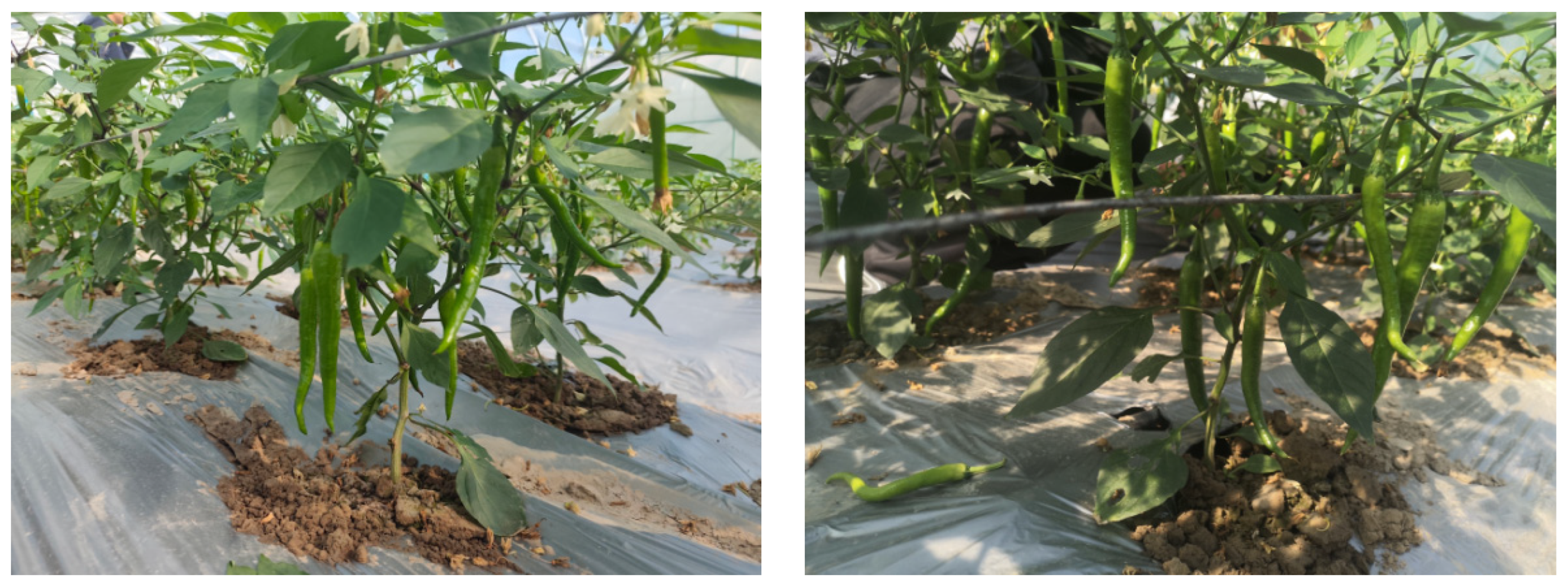
Hang pepper cultivated at a research institute base in Hangzhou was selected as the experimental object. The growing environment is shown in Figure 1. All samples were mature fresh fruits collected from the field. To ensure sample representativeness, fruits with different diameters, lengths, and shapes were selected during harvesting. After being transported to the laboratory, the samples were numbered, and fruit diameter, pedicel diameter, fruit length, pedicel length, and fruit mass were measured and recorded.
The average fruit length was 127.39 mm, with a range of 114.7–145.5 mm; the average pedicel length was 33.74 mm, with a range of 27.2–43.5 mm; the average fruit diameter was 12.32 mm, with a range of 10.58–13.98 mm; the average pedicel diameter was 4.03 mm, with a range of 3.54–4.72 mm; and the average fruit mass was 5.62 g, with a range of 4.9–6.9 g.

2.2. Radial Compression Test of Hang Pepper Fruit

Hang pepper fruit is a natural polymer composite material and exhibits anisotropic characteristics. Previous studies have investigated the mechanical properties of stalks such as corn, maize, sugarcane, and Ficus macrocarpa [21,22,23,24,25]. Since only radial compression is involved during Hang pepper harvesting, radial compression tests were conducted.
In the radial compression tests, straight sections from the middle part of Hang pepper fruits were selected to prepare specimens with lengths of 10–15 mm. The upper, middle, and lower diameters of each specimen were measured using a micrometer, and the average diameter was calculated for subsequent analysis. A universal testing machine was used to compress the specimens, and displacement-load curves were obtained during the compression process.
The radial compression displacement-load curves showed that the fruit did not exhibit a distinct crushing point or abrupt load change in the radial direction. Instead, the load increased continuously with displacement, making it difficult to determine a maximum pressure and therefore to calculate radial compressive strength or radial elastic modulus. Moreover, when compression reached a certain level, the fruit had already been damaged. Thus, this method could not accurately calculate or characterize the true radial compressive strength of the fruit.
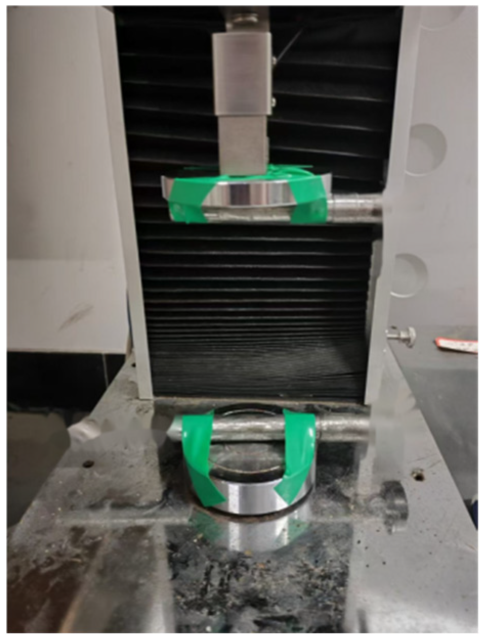
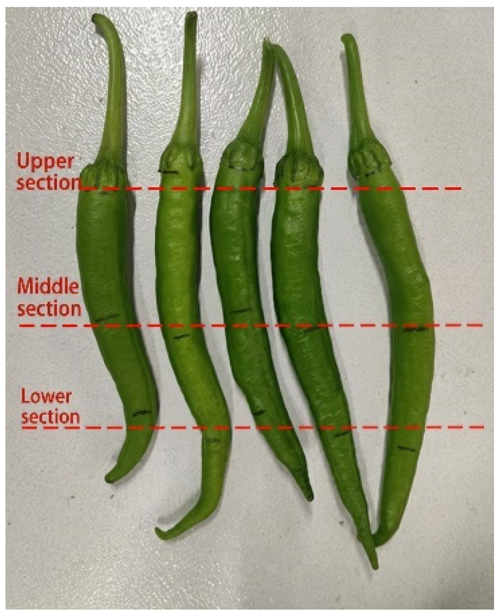
To address this problem, the calculation of radial compressive strength and radial elastic modulus was converted into the determination of the maximum allowable pressure. A shaft with a diameter of approximately 20 mm was placed on both the upper and lower surfaces of the testing machine, as shown in Figure 2. During the test, the specimens were compressed using the universal testing machine to simulate the process of the end-effector grasping pepper fruits. Multiple compression tests were performed on the upper, middle, and lower sections of the fruit, as shown in Figure 3.
During compression tests, fresh Hang pepper fruit was found to be plump and relatively firm. It was observed that fresh Hang pepper fruits were smooth and relatively firm. Under a small pressure, the fruit was slightly compressed and recovered its original shape after unloading or exhibited only minor unrecoverable deformation. However, under a larger pressure, the internal tissue was damaged even when no visible surface injury occurred. The compressed region became soft, and the fruit could not recover its original diameter, resulting in substantial deformation. Because surface damage and softening are difficult to quantify, the deformation degree was proposed to characterize the effect of pressure on Hang pepper. The deformation degree was calculated using Equation (1).
ε = D 1 D
where D is the measured diameter of the specimen before compression, mm; D 1 is the measured diameter after pressure release, mm; and ε is the deformation degree.
In preliminary experiments, pressure was gradually applied from 0 N with an increment of 1 N. When the pressure was between 0 and 2 N, the deformation degree after unloading was less than 1%, indicating almost no deformation. When the pressure exceeded 6 N, the deformation degree after unloading exceeded 10%. Although no obvious surface scar was observed, the flesh had become soft, indicating internal tissue damage. Therefore, in the formal tests, the pressure range was set to 2–6 N with an increment of 0.5 N. After the target pressure was reached, it was immediately released and the specimen diameter was measured. Three positions of five specimens were tested. The data for specimen 1 are shown in Table 1.
A post-release deformation degree of less than 5% was used as the low-damage criterion. The maximum allowable pressures were 4.5 N at the lower section, 3.5 N at the middle section, and 4 N at the upper section. Therefore, the maximum allowable clamping force was determined as 3.5 N. When this maximum clamping force was introduced into the radial compression displacement-load curve, the displacement at a load of 3.5 N was 1.139 mm, corresponding to a strain of 9.51%, which was rounded to 10%.

2.3. Mechanical Properties of the Hang Pepper Pedicel

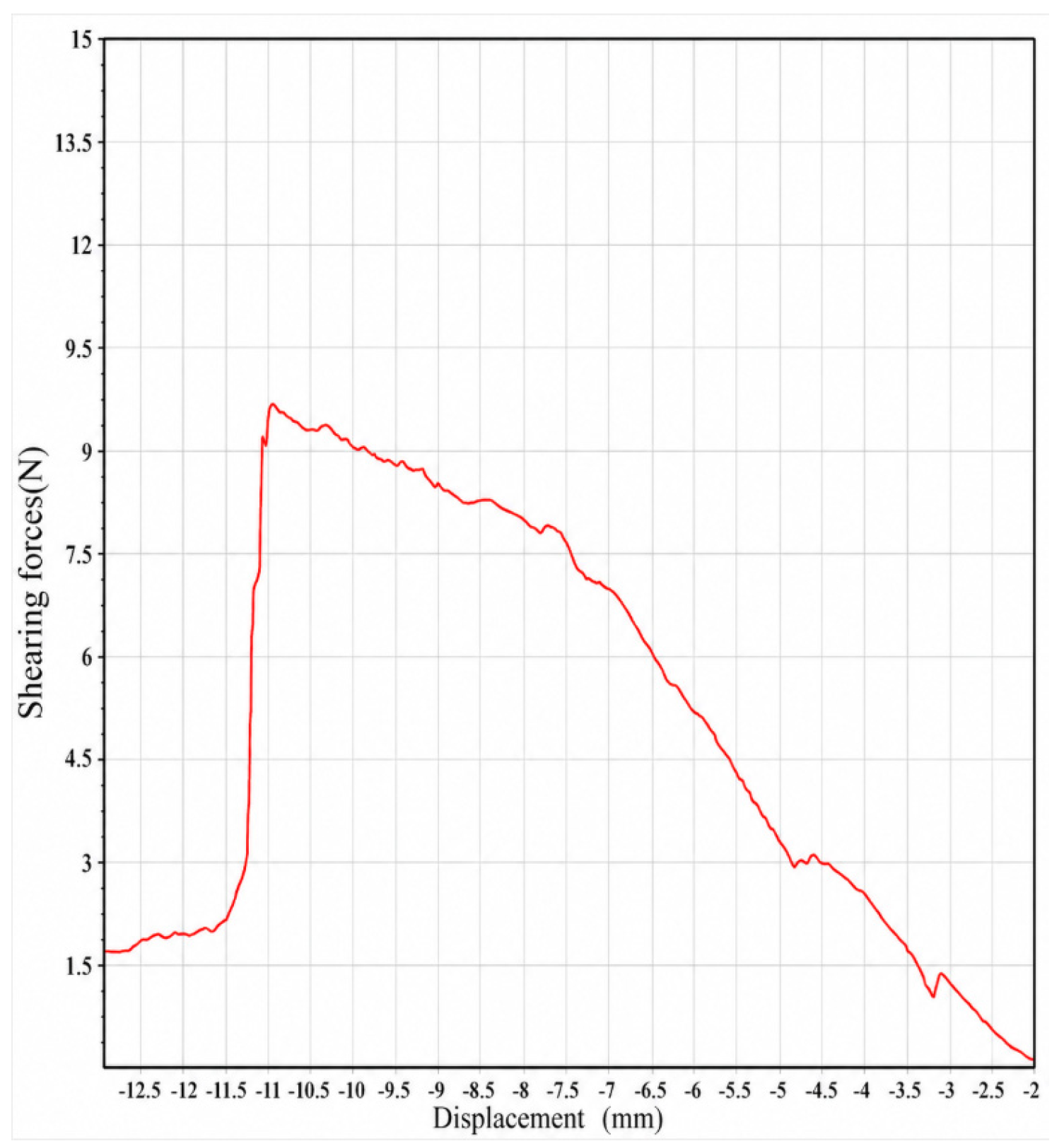
During Hang pepper harvesting, the pedicel needs to be cut. Therefore, the maximum shearing force required for the blade to cut the pedicel must be determined. Five pedicel specimens were tested. The displacement-shearing force curve of specimen 1 is shown in Figure 4, and the 1maximum shearing forces of all specimens are listed in Table 2.
As shown in the table, the maximum shearing force was 15.03 N and the average shearing force was 12.21 N. The maximum shearing force was adopted as the characteristic value for the subsequent analysis.

2.4. Design Principle of the End-Effector

Based on the physical characteristics, growth environment, and growth patterns of Hang pepper, it was found that dense branches and leaves frequently occlude some fruits and pedicels. If the pedicel is selected as the picking target, fruits with occluded pedicels cannot be harvested. If the fruit is used as the target and is simply pulled outward until the pedicel detaches from the branch, the plant and fruit may be damaged, and severe shaking of the plant may negatively affect subsequent harvesting. Since Hang pepper fruits vary in diameter and length, establishing a unified harvesting method is challenging. However, if the fruit is used as the harvesting target point and a universal harvesting strategy applicable to different fruit positions can be developed, effective harvesting can be achieved regardless of pedicel occlusion, greatly reducing target recognition difficulty and improving harvesting success rate.
Therefore, a roller pull-down end-effector with a working sequence of fruit clamping, fruit pull-down, and pedicel cutting -clamping was proposed. The end-effector consists of two coordinated mechanisms: an integrated cutting-and-clamping mechanism and a pull-down mechanism. The integrated cutting-and-clamping mechanism must perform both fruit clamping and pedicel cutting -clamping. Because the diameters of the fruit and the pedicel differ, the motion amplitude at the driving end distinguishes the executed action. A five-bar linkage was therefore selected to realize this function.
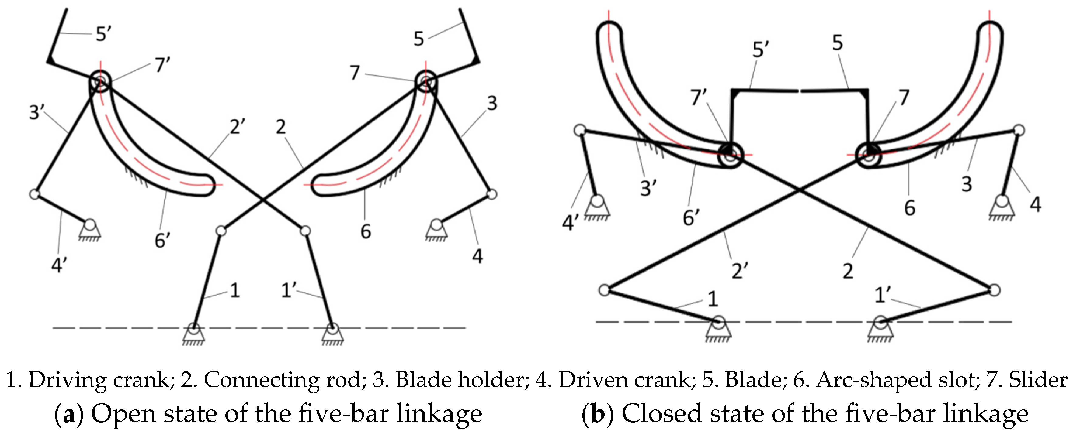
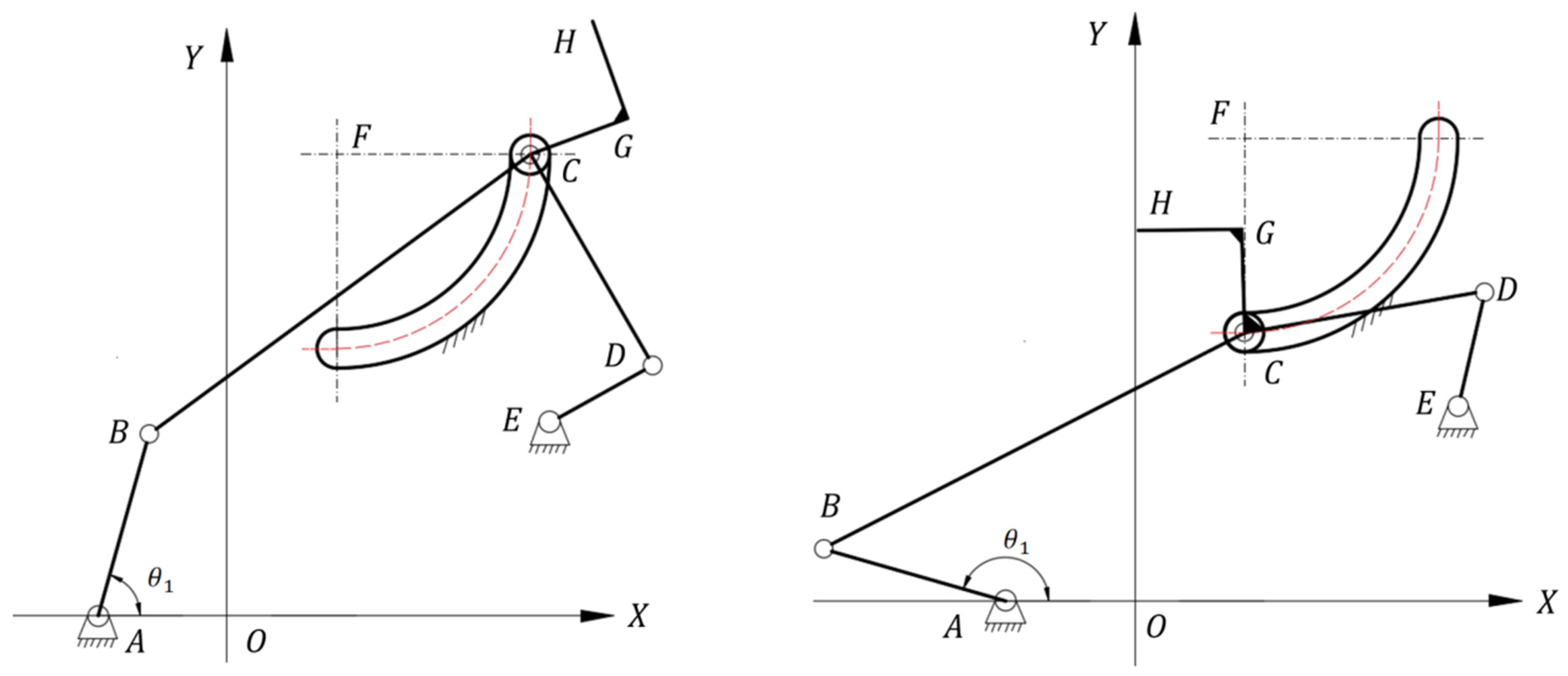
The integrated cutting -clamping mechanism consists of a pair of symmetrically staggered five-bar linkages. The two five-bar linkages transmit power through gear engagement at the driving ends, enabling simultaneous opening and closing. The open and closed states of the five-bar linkage are shown in Figure 5.
In this five-bar linkage, the driving crank at the lower left is connected to the servo motor as the power input. Power is transmitted to the driving crank of the other five-bar linkage through gear meshing on the shaft. At the slider, a vertical shaft passes through the slider; this shaft is the roller shaft. The connecting rod, blade holder, slider, and flexible roller are mounted on the roller shaft. The slider moves along an arc-shaped slot, and the roller shaft therefore follows the same arc path. The blade holder consists of three rods connected rigidly at specified angles. Counterclockwise rotation of the driving crank moves the slider and blade holder to the left, realizing the clamping action.
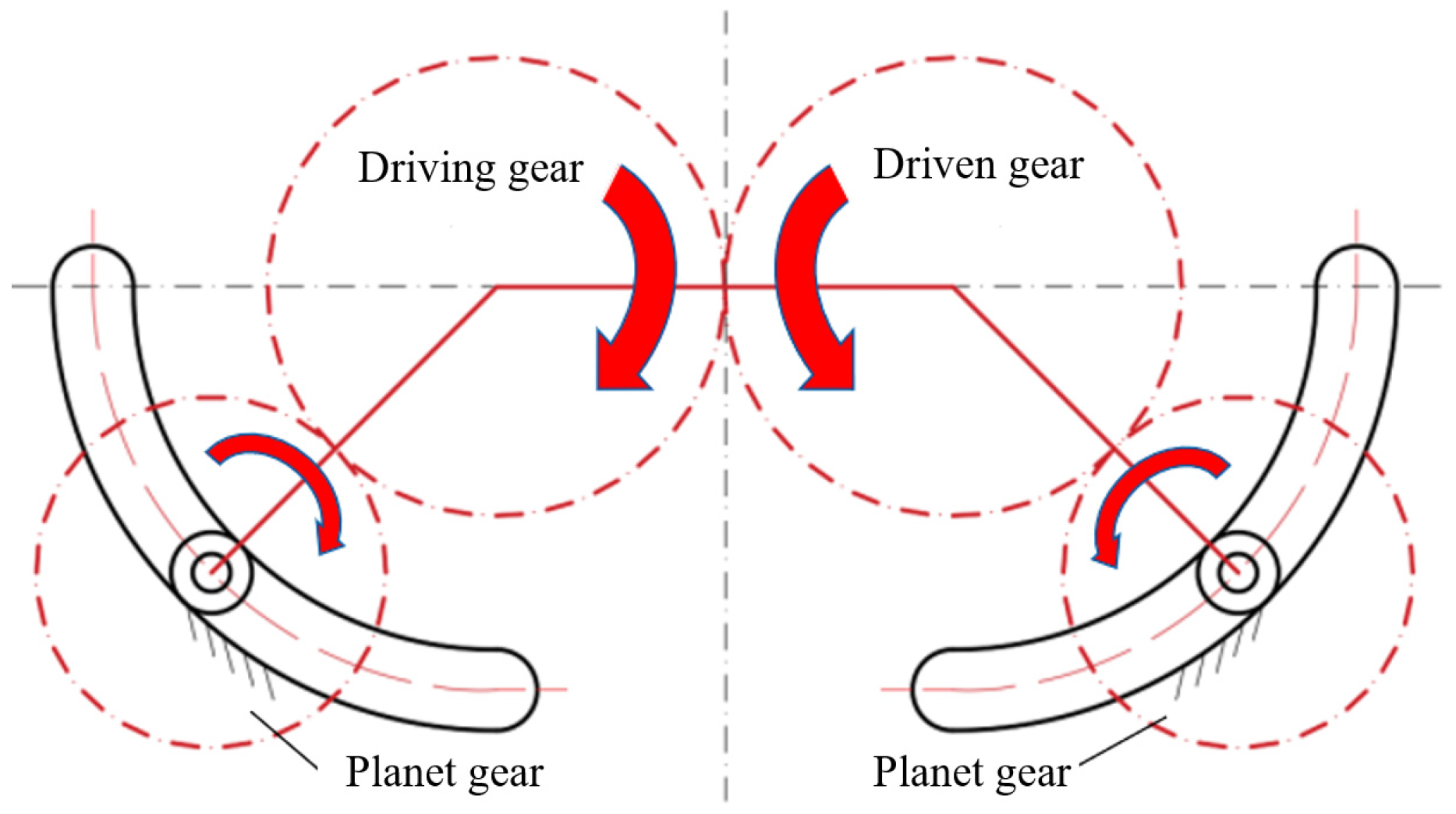
When this five-bar linkage is used for clamping, the distance between the axes of the two rollers changes, and the opening degree of the clamping device varies during harvesting. Therefore, the transmission mode of the pull-down device was designed as the structure shown in Figure 6. The structure consists of two meshing sun gears and two planetary gears, enabling the gears on the roller shafts to remain engaged with the sun gears at different roller-shaft positions and thereby solving the roller-shaft driving problem.
The front rollers directly contact the pepper fruit; therefore, the pressure applied to the pepper during clamping must be controlled. Two schemes were considered: (1) attaching thin-film pressure sensors to the roller surfaces to measure pressure in real time and adjust the opening degree of the roller gripper; (2) designing the roller gripper as a flexible structure with deformation capacity to protect the pepper fruit. Practical tests showed that because the roller gripper diameter is small, approximately 20 mm, the thin-film pressure sensor, which is relatively stiff, is difficult to fit tightly to the roller surface. f the thin-film pressure sensor does not closely conform to the roller gripper surface, measurement errors may occur, and the measured pressure may even decrease during the clamping process. Therefore, this scheme was abandoned, and the flexible roller-gripper scheme was adopted to control the pressure applied to the pepper.
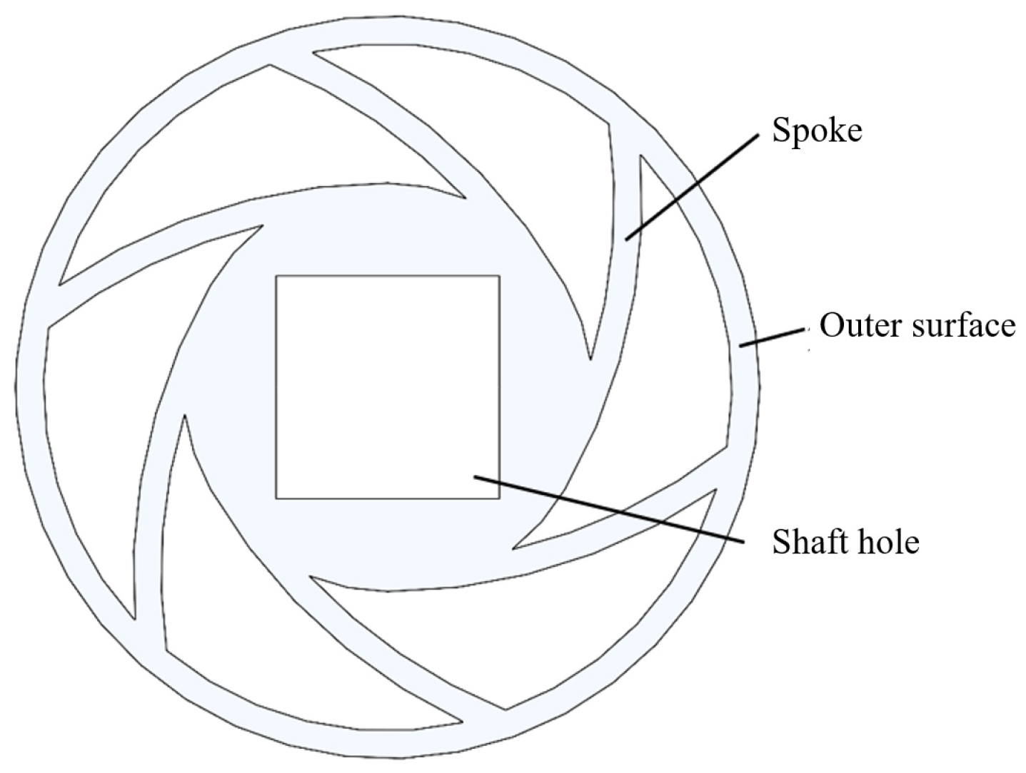
The roller gripper was designed as shown in Figure 7. The gripper consists of inner and outer layers connected by thin spokes. The spokes deform with changes in pressure and temporarily alter the local clamping distance, thereby protecting the pepper fruit. The outer ring is thin and also has good deformability. During initial clamping or when the fruit diameter increases during pull-down, the outer ring produces a wrapping effect, increases the contact area, and reduces stress. Silicone was used to fabricate the roller gripper to increase friction and improve the pull-down action. To keep the two rollers as parallel as possible and reduce skewing under external forces, two sliders were installed on the roller shaft to maintain verticality. Considering the clearance between the slot and the slider, a planetary carrier was additionally added between the roller driving shaft and the roller shaft. This ensured the center distance between the two shafts and maintained shaft verticality.
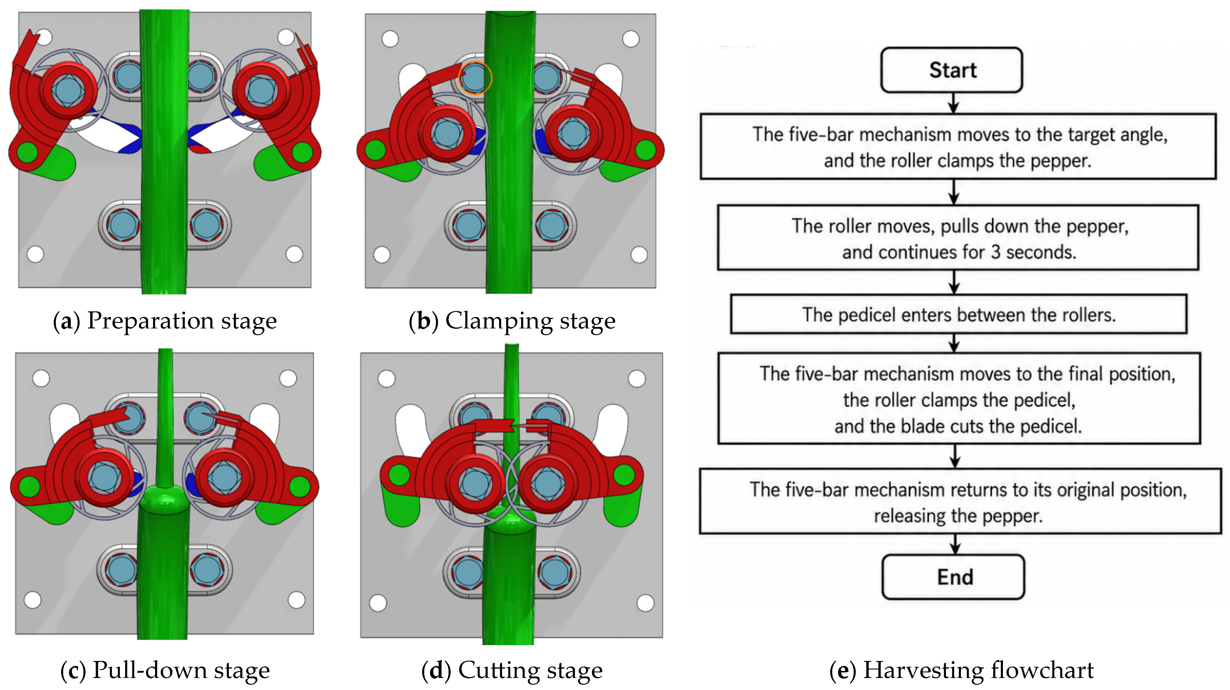
The harvesting workflow of the end effector is as follows. Preparation stage, the clamping device opens to its maximum extent to allow the Hang pepper fruit to enter. The manipulator moves the end-effector toward the target according to the calculated picking target point, target diameter, and pose information, and stops when the pepper enters the gripper region. Clamping stage, the servo of the cutting-clamping mechanism rotates by an angle calculated from the diameter of the target point on the fruit, causing the roller grippers to hold the fruit. Pull-down stage, the servo of the pull-down mechanism then rotates counterclockwise, driving the two roller grippers to rotate in opposite directions and pull the fruit downward. After a certain pull-down time, the pedicel is drawn between the roller grippers. Although the branch still applies a tensile force to the pepper, the fruit is not pulled back between the grippers because the distance between the grippers is smaller than the fruit diameter. Meanwhile, since the pedicel diameter is smaller than the gripper spacing, so further roller rotation no longer pulls the pepper downward. Cutting stage, the servo of the cutting-clamping mechanism then moves to the limited maximum angle, the blade holders approach each other, the blade enters the knife slot and cuts the pedicel, and the rollers fully close to clamp the pedicel. The cutting-clamping mechanism maintains this state while the manipulator moves the end effector to the designated collection point. Finally, the servo resets, the fruit is released, and one harvesting cycle is completed. The harvesting process is shown in Figure 8.

2.5. Kinematic Analysis of the Five-Bar Linkage

To simplify the model, only one half of the mechanism was analyzed in the kinematic analysis, as well as in the subsequent dynamic analysis and link optimization.
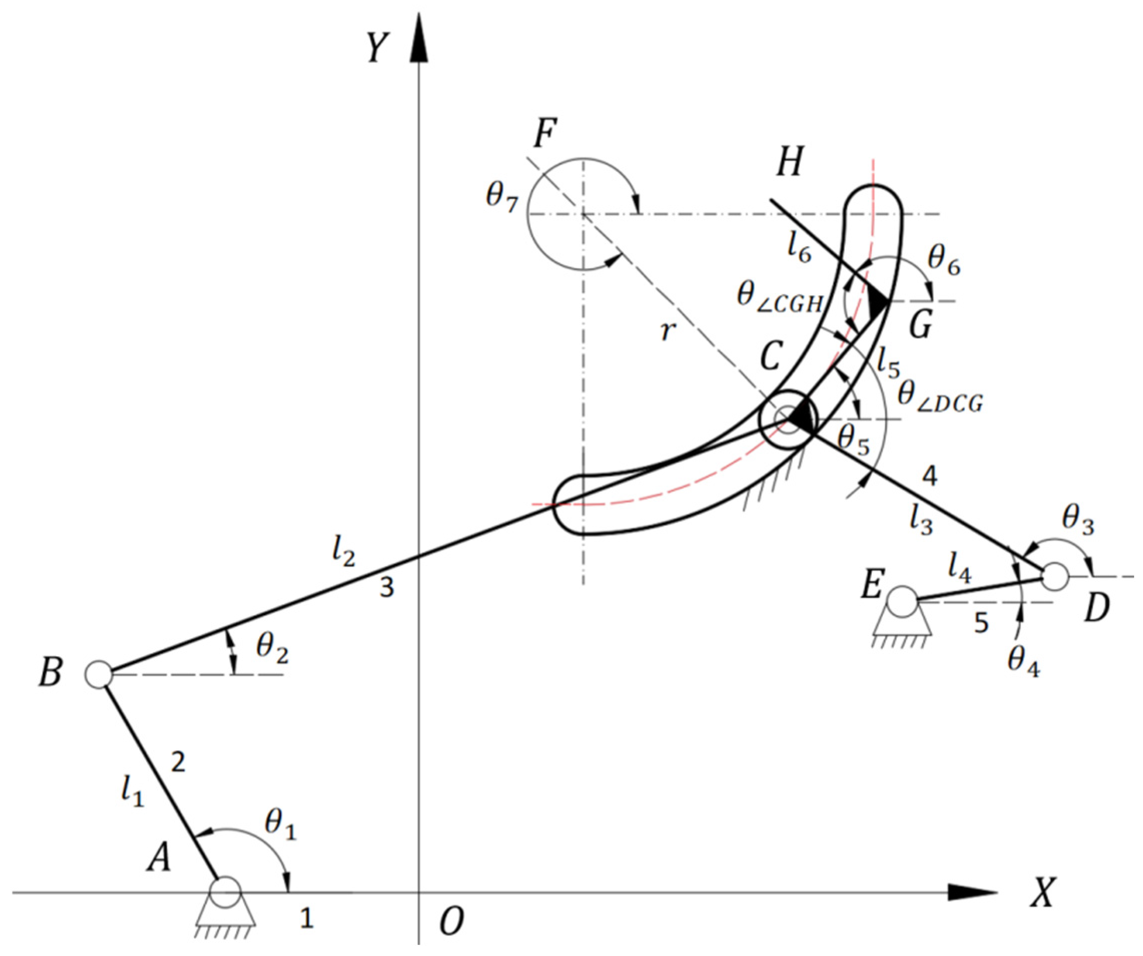
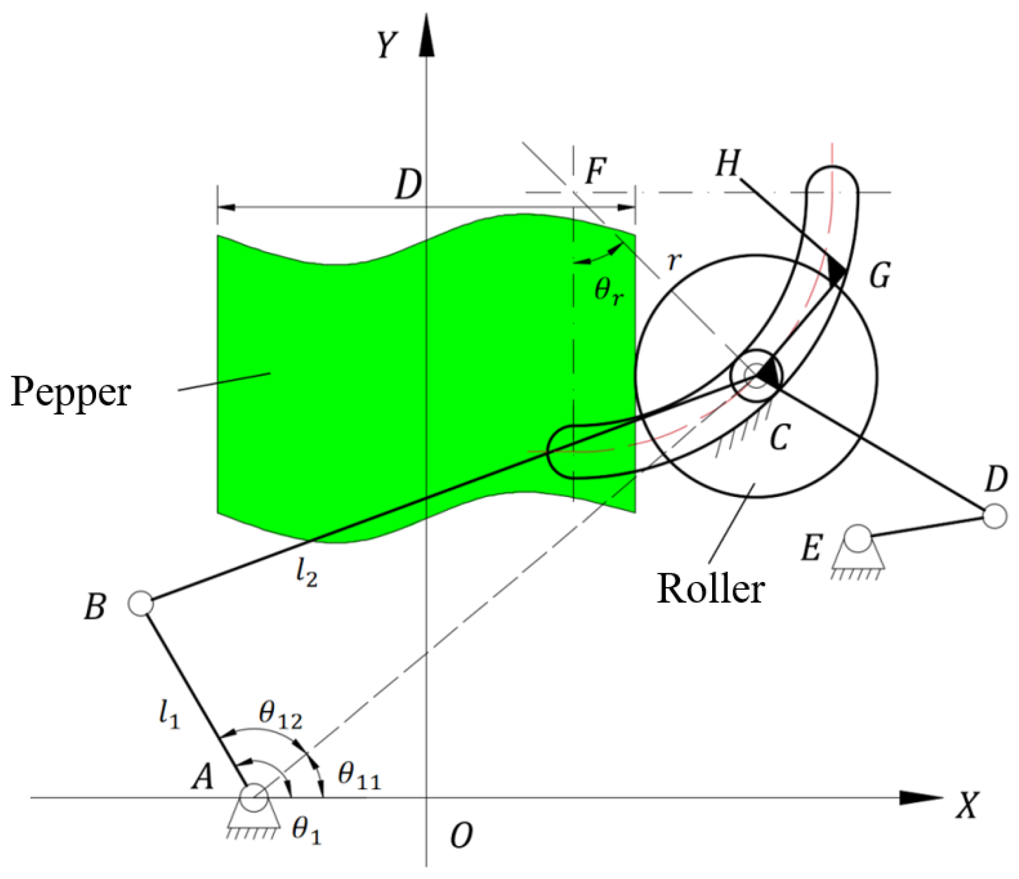
A coordinate system was established according to the structural schematic, as shown in Figure 9. The X-axis is defined as the line connecting the driving shafts of the two five-bar linkages, and the Y-axis is the perpendicular bisector of this line. In the kinematic analysis, the roller and the blade, corresponding to Points C and H, respectively, were selected as the objects of interest, and their velocities and accelerations were calculated. The kinematics of the five-bar linkage were analyzed using an analytical method, with the counterclockwise direction defined as positive.
  • Coordinate calculation of each point
According to the link lengths and motion mode, The coordinates of point C are calculated from point A, and the coordinates of points F and E are calculated from point C. Meanwhile, to simplify the description of the subsequent moment equilibrium equations, the values of x E , y E , x F and y F were assigned to b , c , d and e .
The eight points A, B, C, D, E, F, G, and H can be expressed as follows:
x A = a y A = 0
x B = l 1 cos θ 1 + a y B = l 1 sin θ 1
x C = l 1 cos θ 1 + l 2 cos θ 2 + a y C = l 1 sin θ 1 + l 2 sin θ 2
x D = x C l 3 cos θ 3 y D = y C l 3 sin θ 3
x E = x D l 4 cos θ 4 = b y E = y D l 4 sin θ 4 = c
x F = x C r cos θ 7 = d y F = y C r sin θ 7 = e
where x is the x-coordinate of each point, mm; y is the y-coordinate of each point, mm; a is the pitch-circle radius of the driving gear on the crank, mm; l 1 is the length of crank AB, mm; θ 1 is the angle between crank AB and the positive x-axis, °; l 2 is the length of connecting rod BC, mm; θ 2 is the angle between connecting rod BC and the positive x-axis, °; b is the distance from point E to the y-axis, mm; c is the distance from point E to the x-axis, mm; l 4 is the length of crank DE, mm; θ 4 is the angle between crank DE and the positive x-axis, °; l 3 is the length of connecting rod CD, mm; θ 3 is the angle between connecting rod CD and the positive x-axis, °; d is the distance from point F to the y-axis, mm; e is the distance from point F to the x-axis, mm; r is the radius of the trajectory of slider C, mm; θ 7 is the angle between CF and the positive x-axis, °.
Thus, the following equations can be obtained:
x G = x C + l 5 cos θ 5 = x C + l 5 cos θ 4 θ D C G y G = y C + l 5 sin θ 5 = y C + l 5 sin θ 4 θ D C G
x H = x C + l 5 cos θ 5 + l 6 cos θ 6 = x C + l 5 cos θ 5 + l 6 cos θ 5 + θ C G H y H = y C + l 5 sin θ 5 + l 6 sin θ 6 = y C + l 5 sin θ 5 + l 6 sin θ 5 + θ C G H
where l 5 is the length of blade holder CG, mm; θ 5 is the angle between blade holder CG and the positive x-axis, °; θ D C G is the included angle between blade holders CD and CG, °; l 6 is the length of blade holder GH, mm; θ 6 is the angle between blade holder GH and the positive x-axis, °; and θ C G H is the included angle between blade holders CG and GH, °.
2.
Acceleration analysis
Taking the second derivative of the displacement equations gives the following:
a c x = l 1 α 1 sin θ 1 l 1 ω 1 2 cos θ 1 l 2 α 2 sin θ 2 l 2 ω 2 2 cos θ 2 = l 4 α 4 sin θ 4 l 4 ω 4 2 cos θ 4 l 3 α 3 sin θ 3 l 3 ω 3 2 cos θ 3 = r α 7 sin θ 7 r ω 7 2 cos θ 7 a c y = l 1 α 1 cos θ 1 l 1 ω 1 2 sin θ 1 + l 2 α 2 cos θ 2 l 2 ω 2 2 sin θ 2 = l 4 α 4 cos θ 4 l 4 ω 4 2 sin θ 4 + l 3 α 3 cos θ 3 l 3 ω 3 2 sin θ 3 = r α 7 cos θ 7 r ω 7 2 sin θ 7
where α 1 is the angular acceleration of crank AB, ° / s 2 ; α 2 is the angular acceleration of connecting rod BC ° / s 2 ; α 4 is the angular acceleration of crank DE; α 3 is the angular acceleration of connecting rod CD; and α 7 is the angular acceleration of CF, ° / s 2 .
a H x = a c x l 5 α 5 sin θ 5 l 5 ω 5 2 cos θ 5 l 6 α 6 sin θ 6 l 6 ω 6 2 cos θ 6 a H y = a c y + l 5 α 5 cos θ 5 l 5 ω 5 2 sin θ 5 + l 6 α 6 cos θ 6 l 6 ω 6 2 sin θ 6
where α 5 is the angular acceleration of blade holder CG, ° / s 2 ; and α 6 is the angular acceleration of blade holder GH, ° / s 2 .

2.6. Dynamic Analysis of the Five-Bar Linkage

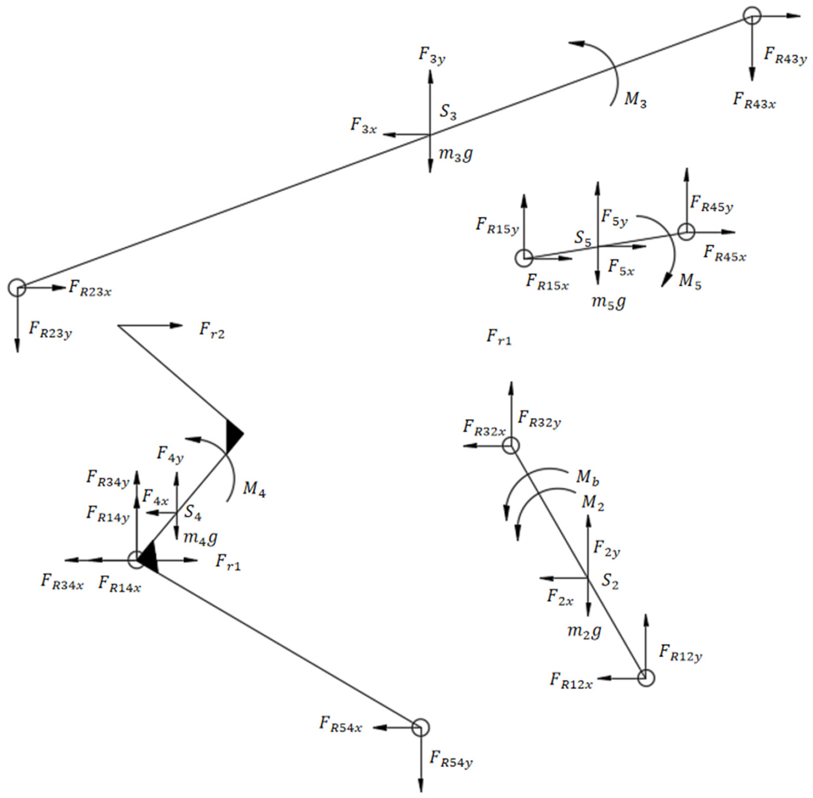
The five-bar linkage was separated at each revolute joint, and force analyses were conducted for each component. Figure 10 shows the free-body diagrams of the separated links. Rigid-body dynamic static calculations were performed to obtain the inertial forces and inertial moments of each link.
M 2 = J S 2 α 1 F 2 x = m 2 a s 2 x F 2 y = m 2 a s 2 y M 3 = J S 3 α 2 F 3 x = m 3 a s 3 x F 3 y = m 3 a s 3 y M 4 = J S 4 α 3 F 4 x = m 4 a s 4 x F 4 y = m 4 a s 4 y M 5 = J S 5 α 4 F 5 x = m 5 a s 5 x F 5 y = m 5 a s 5 y
where M 2 is the inertial moment of crank AB, N m ; M 2 is the inertial moment of rod BC, N m ; M 4 is the inertial moment of left blade holder, N m ; M 5 is the inertial moment of rod DE, N m ; J S 2 is the moment of inertia of crank AB, kg m 2 ; J S 3 is the moment of inertia of rod BC, kg m 2 ; J S 4 is the moment of inertia of left blade holder, kg m 2 ; J S 5 is the moment of inertia of crank DE, kg m 2 ; F 2 x and F 2 y are the X-axis and Y-axis components of the inertial force of crank AB, N ;   F 3 x and F 3 y are the X-axis and Y-axis components of the inertial force of rod BC, N ;   F 4 x and F 4 y are the X-axis and Y-axis components of the inertial force of left blade holder, N ; and F 5 x and F 5 y are the X-axis and Y-axis components of the inertial force of crank DE, N .
Crank AB, connecting rod BC, and crank DE were regarded as homogeneous rods, with their centers of mass located at the rod midpoints. The moment of inertia and mass were calculated using Equations (17) and (18), respectively. Because the blade holder has a complex structure, most of its mass is concentrated in the flexible roller, and linkage optimization has little influence on its mass and moment of inertia. Therefore, the unoptimized blade holder was calculated in SolidWorks 2024 to obtain its mass m 4 and moment of inertia J S 4 , which were then used as fixed values in the calculation.
J S n = 1 12 m n l n 1 2 , n = 2 , 3 , 5
m n = ρ v = ρ l n h n w n , n = 2 , 3 , 5
where h is the thickness of the rod, mm; and w is the width of the rod, mm.
The five-bar linkage contains five hinge points. Each link is subjected to horizontal and vertical force components at the hinge points. In addition, the force exerted by the roller shaft on the frame at point C and the unknown driving torque must be considered, resulting in 13 unknowns. According to the force and moment equilibrium conditions shown in Equation (19), equilibrium calculations were performed for each link, yielding a system of 13 equations.
M S n = 0 F x n = 0 F y n = 0 , n = 2 ,   3 ,   4 ,   5
C F R = D
where C is the coefficient matrix, F R is the vector of unknown forces, and D is the vector of known forces.
C = 1 ( y A y s 2 ) ( x A x s 2 ) ( y s 2 y B ) ( x s 2 x B ) 0 0 0 0 0 0 0 0 0 1 0 1 0 0 0 0 0 0 0 0 0 0 0 1 0 1 0 0 0 0 0 0 0 0 0 0 0 ( y s 3 y B ) ( x s 3 x B ) ( y C y s 3 ) ( x C x s 3 ) 0 0 0 0 0 0 0 0 0 1 0 1 0 0 0 0 0 0 0 0 0 0 0 1 0 1 0 0 0 0 0 0 0 0 0 0 0 ( y s 4 y C ) ( x s 4 x C ) ( y D y s 4 ) ( x s 4 x D ) ( y s 4 y C ) ( x s 4 x C ) 0 0 0 0 0 0 0 0 0 1 0 1 0 0 0 0 0 0 0 0 0 1 0 1 0 1 0 0 0 0 0 0 0 0 0 ( y s 5 y D ) ( x D x s 5 ) 0 0 ( y s 5 y E ) ( x E x s 5 ) 0 0 0 0 0 0 0 1 0 1 0 1 0 0 0 0 0 0 0 0 0 1 0 0 0 1 0 0 0 0 0 0 0 0 0 tan θ 7 1 0 0
F R = M b F 12 x F 12 y F 23 x F 23 y F 34 x F 34 y F 45 x F 45 y F 14 x F 14 y F 15 x F 15 y          D = M 2 F 2 x m 2 g F 2 y M 3 F 3 x m 3 g + F 3 y M 4 F r 1 ( y H y s 4 ) + F r 2 ( y s 4 y C ) F r 1 + F r 2 F 4 x m 4 g F 4 y M 5 F 5 x m 5 g F 5 y 0
where M b is the external driving torque, N m ; F 12 x and F 12 y are the x and y components of the constraint force at hinge A, N ; F 23 x and F 23 y are the x and y components of the constraint force at hinge B, N ; F 34 x and F 34 y are the x and y components of the constraint force at hinge C, N ; F 45 x and F 45 y are the x and y components of the constraint force at hinge D, N ; F 15 x and F 15 y are the x and y components of the constraint force at hinge E, N ; F 14 x and F 14 y are the x and y components of the force exerted by the slot on the slider at point C, N ; F r 1 is the force exerted by the pedicel on the roller when the pedicel is clamped, N ; and F r 2 is the force exerted by the pedicel on the blade during cutting, N .

2.7. Link-Length Optimization

Based on the kinematic and dynamic analyses presented above, a genetic algorithm was employed to optimize the coordinates of selected fixed pivots, the included angles between links, and the lengths of individual links. The equilibrium matrix established above was used as the constraint equation, and the optimization objective was to minimize the required driving torque. The fixed pivot locations and the included angles of the cutter holder were optimized under the following constraints:
  • To ensure that the blade and knife slot can close when the mechanism reaches its final position. the condition is set such that when θ 7 = 270 ° , x H is close to 0, with the interval being [ 0.5 ,   0.5 ] ;
  • To ensure that the blade cuts the pedicel in a posture perpendicular to the pedicel, the condition is set such that when θ 7 = 270 ° , the angle between GH and the X-axis is close to 0, with the interval being [ 5 ° ,   5 ° ] ;
  • To ensure that the blade velocity is directed along the negative X-axis during pedicel cutting, the condition is set such that when θ 7 = 270 ° , the angle between the velocity direction of point H and the positive X-axis is in the interval [ 175 ° ,   185 ° ] ;
  • To ensure that the blade does not contact the fruit during fruit clamping and pull-down, it is set that when x C 13 mm , x H x C 5 mm .
Based on the previous study on the physical characteristics of peppers, a preliminary design of the structure is conducted, specifying fixed values for coordinates of some fixed hinges, ranges for lengths of connecting rods, ranges for coordinates of some fixed hinges, and ranges for the blade holder angle:
  • Fixed values: the coordinates of point A are ( 10 ,   0 ) , the x-coordinate of point F was 8.5 mm, and r is 15 mm;
  • Rod length ranges: the ranges of l 1 , l 2 , l 3 , l 4 , l 5 , l 6 are [ 12 ,   16 ] , [ 35 ,   41 ] , [ 13 ,   19 ] , [ 8 ,   11 ] , [ 12 ,   13 ] , [ 10 ,   12 ] , respectively;
  • Blade holder angle ranges: The angle range between CD and CG is [ 70 ° ,   90 ° ] , and the angle range between CG and GH is [ 90 ° ,   100 ° ] ;
  • Coordinate ranges of fixed hinges: The abscissa range of point E is [ 25 ,   30 ] , the ordinate range of point E is [ 12 ,   15 ] , and the abscissa range of point F is [ 30 ,   40 ] .
All the above constraints can be represented by intervals. Assuming the interval of a variable x is [ a ,   b ] , the penalty function is constructed as f z g x = τ ( 1 m a x ( x a , 0.01 ) + 1 m a x ( b x , 0.01 ) ) ,where τ = 10 10 .
Through the above analysis, it can be seen that the value of the driving torque is related to the rod length. The initial value of θ 7 is set to 360°, and at the end θ 7 = 270 ° . The crank AB rotates at a constant speed, with the rotational speed ω 1 set to 30   ° / s . The clamping force F r 1 of the roller on the fruit pedicel is set to 18 N, and the shearing force of the blade on the fruit pedicel is 15 N.
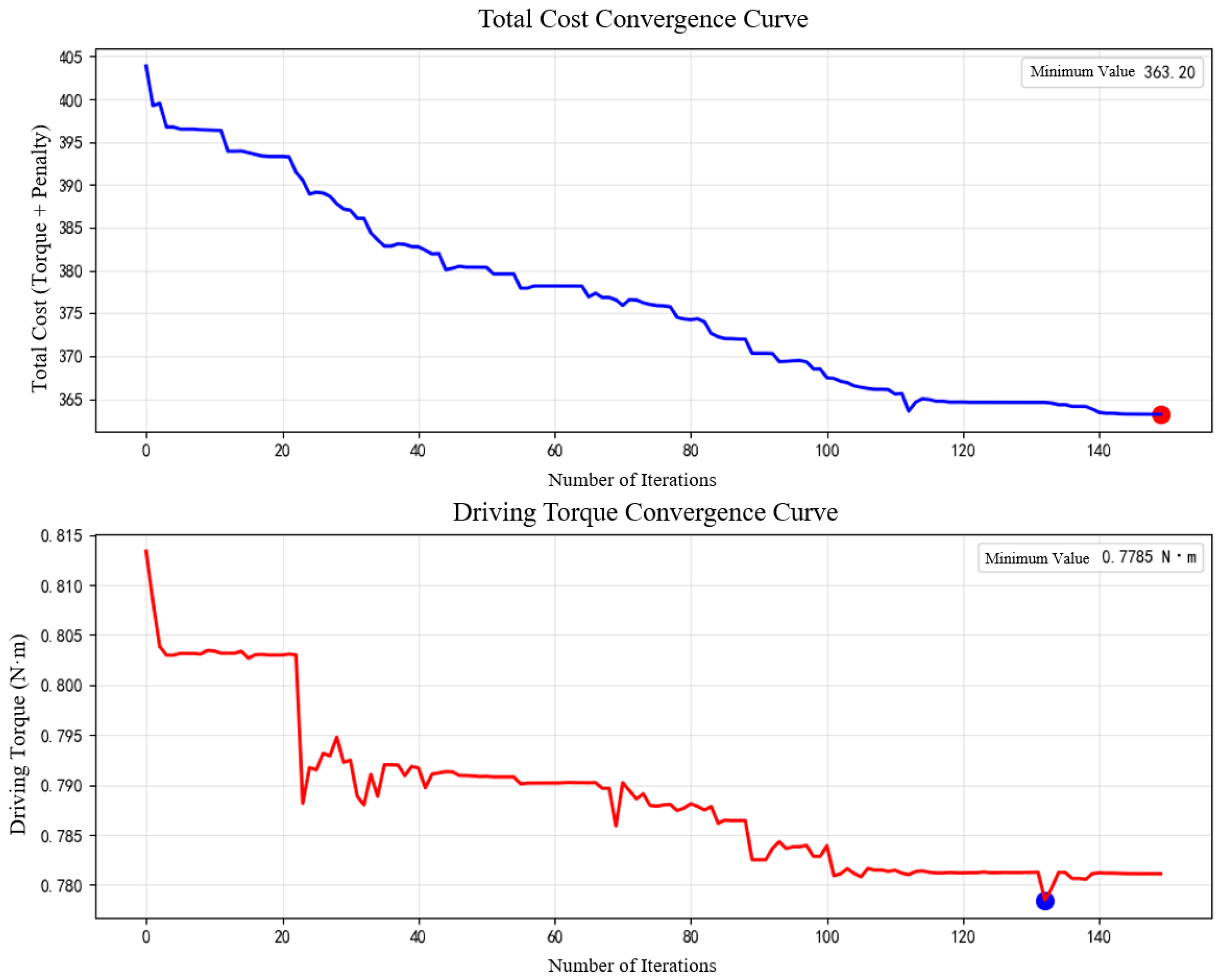
The optimization program was implemented in Python 3.11.10 using a genetic algorithm. The population size was set to 200, the maximum number of iterations was set to 150, the crossover fraction was set to 0.8, and the mutation operation used the default adaptive feasible mutation function. The convergence criterion was determined by Python’s default stopping conditions, including the change in the best fitness value and the maximum stall generations. The loss curve and driving-force convergence curve during optimization are shown in Figure 11, and the optimized link-length results are listed in Table 3.
According to the optimization results, the minimum driving torque corresponding to the minimum loss was 0.781 N m . After rounding the optimized parameters to one decimal place, the results listed in Table 4 were obtained, and the corresponding driving torque was calculated to be 0.801 N m .

2.8. 3D Modeling of the End-Effector

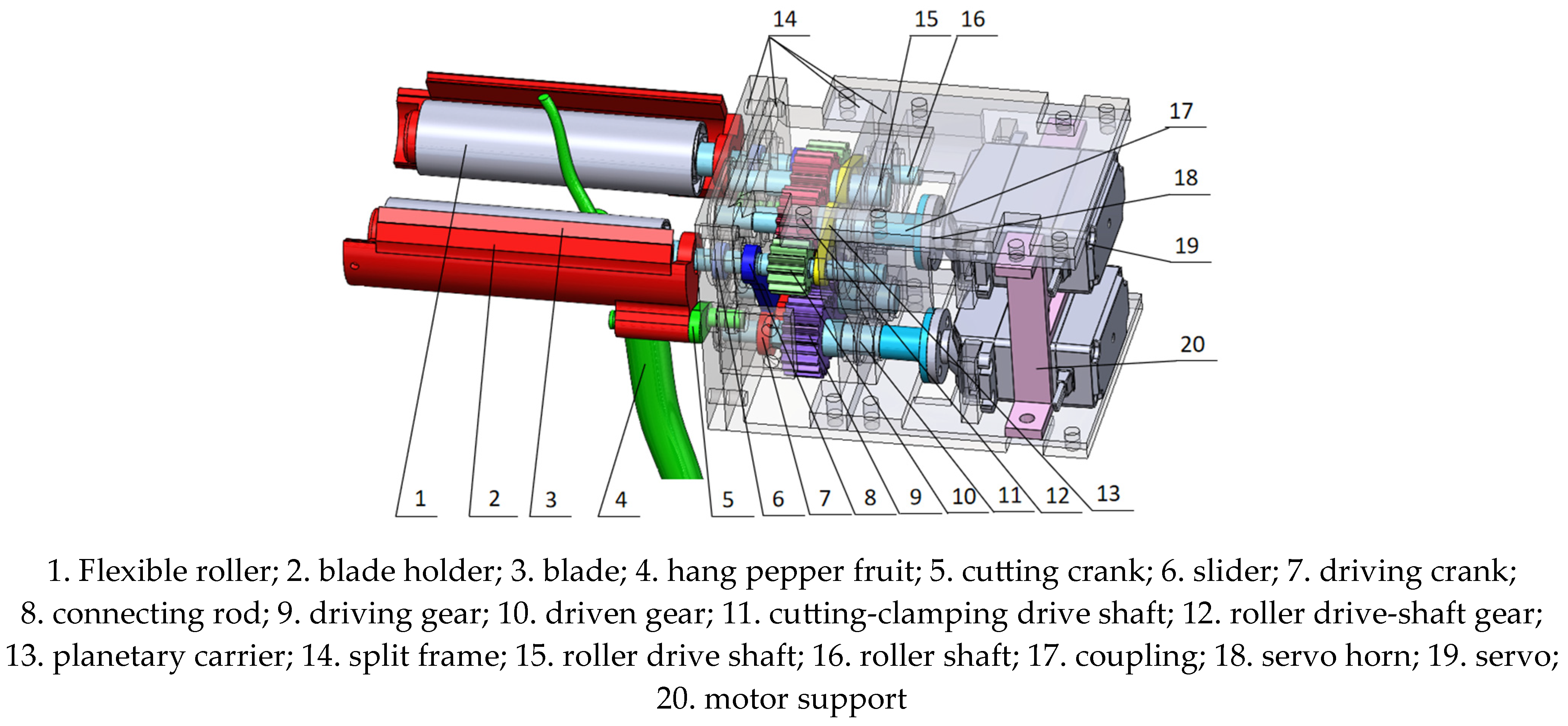
The end-effector was designed according to the selected scheme described above, and a three-dimensional model was established, as shown in Figure 12. The end-effector consists of flexible rollers, blade holders, blades, gears, split frames, linkage mechanisms, couplings, servos, and other components.

2.9. Calculation of the Five-Bar Linkage Motion Angle

In end-effector control, the microcontroller receives the start signal and servo rotation angle data from the host computer. The servo rotation angle is calculated from the target-point diameter. Figure 13 shows the initial and final states of the end effector, which were calculated as 74.2° and 164.1°, respectively.
Figure 14 shows the schematic diagram of the roller clamping Hang pepper, and the coordinate system was established accordingly.
The servo rotation angle can be calculated from the diameter of the harvesting target point as follows:
Given the coordinates of point A ( x A , y A ) , coordinates of point F ( x F , y F ) , length of rod AB l 1 , length of rod BC l 2 , radius of the slot r , roller diameter D 1 , and Hang pepper diameter D . Considering that the fruit strain under the maximum allowable clamping force was 10% according to the physical property tests, the distance between the two roller surfaces during pepper clamping can be determined as 0.9 D , from which the coordinates of point C can be calculated.
x c = 0.45 D + 0.5 D 1
θ r = arcsin x c x F r
y c = y F r cos θ r
where ( x C , y C ) denotes the coordinates of point C, and θ r is the angle between CF and the Y-axis.
After the coordinates of point C are obtained, the relevant angles and link parameters can be calculated as follows:
θ 11 = arctan y c x c x A
l A C = y c 2 + ( x c x A ) 2
θ 12 = arccos l 1 2 + l A C 2 l 2 2 2 l 1 l A C
θ 1 = θ 11 + θ 12
where θ 11 is the angle between AC and the X-axis, and θ 12 is the angle between AC and AB.
The difference between the calculated angle θ 1 and the initial-state angle is the servo rotation angle required during the pepper-clamping stage.

3. Results

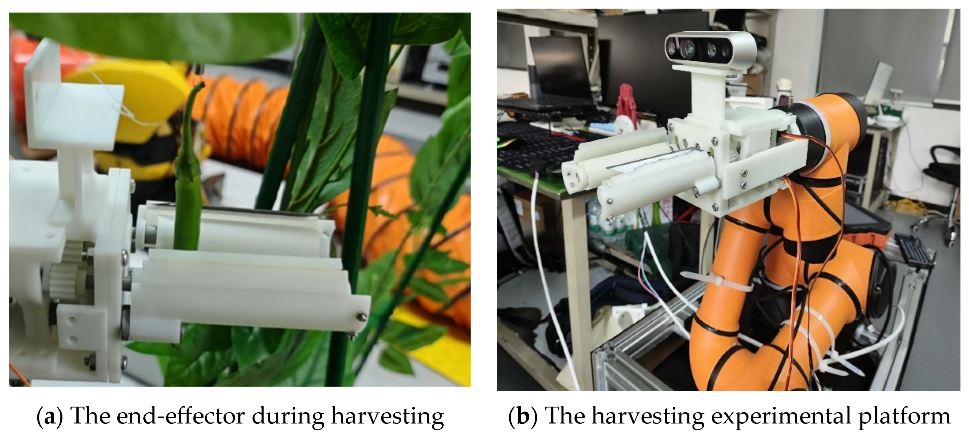
In March 2026, to verify the harvesting performance of the end effector, the end effector was manually moved to the picking target point, and a prescribed servo motion angle was applied to complete harvesting. As shown in Figure 15, 20 Hang pepper fruits were tested, and the harvesting results were recorded. The results of this preliminary test are listed in Table 5.
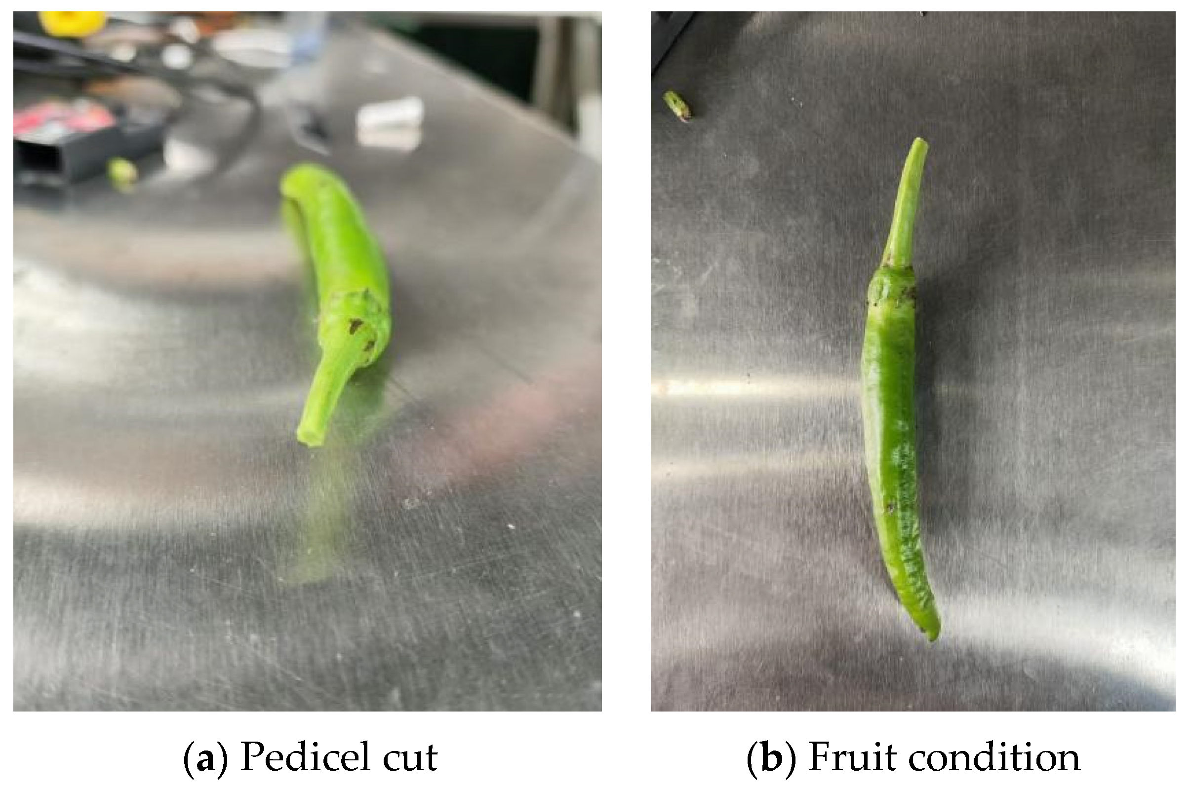
The results showed that the harvesting success rate of the end-effector reached 95% under controlled positioning conditions. Harvesting failures mainly occurred in fruits with small diameters and low firmness. For instance, sample 14 had a diameter of only 10.24 mm and was immature with a relatively soft texture. The insufficient clamping stability reduced the effectiveness of pull-down force transmission, ultimately resulting in harvesting failure. Because the motion time of each servo in the end-effector control system was fixed, the time required for a single harvesting operation was also fixed, at approximately 5.1 s. Successfully harvested fruits were examined for fruit condition and pedicel cut quality, as shown in Figure 16. The fruit remained intact, with no surface damage and no softening caused by squeezing during pulling process. The cut surface of the pedicel was smooth and flat. Although a slight compression mark caused by the roller was observed on the pedicel, it was insignificant and had no adverse effect on the fruit.

4. Discussion

The experimental results demonstrated that the proposed pulling–cutting–clamping end-effector achieved reliable harvesting performance under prescribed target-point conditions, with a success rate of 95% and an average harvesting time of 5.1 s per fruit. These results indicate that the proposed harvesting strategy can effectively realize selective harvesting of Hang pepper by establishing a stable mechanical interaction with the fruit body.
Previous pepper harvesting end-effectors include cutting types [10], clamping-and-cutting types [11], suction cup types [17], and flexible gripper types [18]. Both cutting and clamping-and-cutting types rely on accurate localization of the pedicel. Although suction cup and flexible gripper types can improve harvesting accuracy by establishing stable contact with the fruit, they still depend on accurate fruit localization. Moreover, these two types of end-effectors are mainly suitable for round fruits such as sweet peppers. Inspired by the design concepts of these end-effectors, the end-effector proposed in this study adopts a flexible cylindrical pulling end effector to grasp the pepper and pull it downward through rolling motion until the pedicel can be cut, thereby reducing the dependence of visual systems on accurate localization of the fruit or pedicel.
Furthermore, the low-damage performance of the end-effector was also closely related to the flexible roller design and the experimentally determined clamping parameters. The maximum allowable clamping force was obtained based on the post-release deformation criterion, which considers not only visible surface damage but also potential internal tissue deformation. The harvested fruits showed no obvious compression damage or softening, indicating that the flexible roller successfully balanced grasping stability and damage prevention.
In conclusion, this study demonstrates that the proposed pulling–cutting–clamping end-effector is a promising solution for selective Hang pepper harvesting.

5. Conclusions

An end-effector for selective Hang pepper harvesting was developed to overcome fruit stem occlusion caused by dense branches and leaves. A fruit-body-based harvesting strategy integrating clamping, pull-down, and pedicel cutting was proposed, and its feasibility was validated through mechanism optimization and harvesting experiments.
  • The morphological characteristics and growing environment of Hang pepper were investigated, and physical parameters such as fruit mass were measured. In radial compression tests, a post-release deformation degree of less than 5% was used as the low-damage criterion. The maximum allowable clamping force was 3.5 N, under which the maximum fruit compression ratio was 10%. The maximum cutting force required to shear the pedicel was 15.03 N.
  • A Hang pepper harvesting end-effector was designed. A harvesting process consisting of fruit clamping, fruit pull-down, and pedicel cutting and clamping was proposed, and an overall end effector scheme based on a five-bar linkage was determined. Kinematic and mechanical models of the end-effector were established. A genetic algorithm was used to optimize the five-bar linkage and determine the linkage dimensions, resulting in a calculated driving torque of 0.801 N m.
  • Harvesting tests were conducted using prescribed target-point diameters. The harvesting success rate reached 95%, and the harvesting time was 5.1 s per fruit, verifying the feasibility of the proposed Hang pepper harvesting end effector system.
Although the proposed end-effector reduces the requirement for direct pedicel observation during harvesting, the influence of different occlusion levels, foliage densities, and branch distributions on harvesting performance was not quantitatively investigated in this study. Future work will focus on developing occlusion-aware perception methods and integrating them with the proposed harvesting mechanism to achieve pepper detection and harvesting under occluded environments.

Author Contributions

Conceptualization, X.M. and H.L.; methodology, X.M.; software, H.L.; validation, M.L. and J.C.; formal analysis, X.M.; investigation, M.L.; resources, X.Z.; data curation, H.L.; writing—original draft preparation, H.L.; writing—review and editing, X.M.; visualization, H.L.; supervision, J.C.; project administration, X.Z.; funding acquisition, X.Z. All authors have read and agreed to the published version of the manuscript.

Funding

This research was funded by the National Key Research and Development Program of China (Grant No. 2022YFD2001803).

Data Availability Statement

The original contributions presented in this study are included in the article. Further inquiries can be directed to the corresponding author.

Conflicts of Interest

Author Mingjie Li and Hongxuan Liang were employed by the company Zhejiang Institute of Mechanical & Electrical Engineering. The remaining authors declare that the research was conducted in the absence of any commercial or financial relationships that could be construed as a potential conflict of interest.

References

  1. Ali, M.M.; Khalid, N.I.; Wondi, M.H.; Haris, N.I.N.; Azman, P.N.M.A. Exploring the nutritional values, volatile compounds, health benefits, and potential food products of chilli (Capsicum annuum): A comprehensive review. Food Chem. 2025, 490, 145091. [Google Scholar] [CrossRef] [Scilit] [PubMed]
  2. Jayan, L.S.; Rajan, S.S.; Mujahid, S.M.; Sharma, S.; Wani, K.M. Capsaicin: An in-depth review of its chemical properties, health benefits and challenges in food applications. Food Prod. Process. Nutr. 2025, 7, 47. [Google Scholar] [CrossRef] [Scilit]
  3. Tai, S.; Tang, Z.; Li, B.; Wang, S.; Guo, X. Intelligent recognition and automated production of chili peppers: A review addressing varietal diversity and technological requirements. Agriculture 2025, 15, 1200. [Google Scholar] [CrossRef] [Scilit]
  4. Kim, C.H.; Silwal, A.; Kantor, G. Autonomous robotic pepper harvesting: Imitation learning in unstructured agricultural environments. IEEE Robot. Autom. Lett. 2025, 10, 3406–3413. [Google Scholar] [CrossRef] [Scilit]
  5. Han, D.; Wang, C.; Zhang, H.; Pang, H.; Wang, X.; Chen, X.; Wen, X. Advances in mechanized harvesting technologies and equipment for chili peppers. Agriculture 2025, 15, 1129. [Google Scholar] [CrossRef] [Scilit]
  6. Lei, M.; Kong, L.; Chen, Y.; Zhou, H.; Duan, Y.; Tian, K. Research on the Chili Picking Device of Spring Tooth Roller-Type. J. Chin. Agric. Mech. 2014, 35, 161–165. [Google Scholar]
  7. Sun, G. Design of 4JZ-3600/2600 Type Movable Pepper Harvester. Agric. Eng. 2012, 2, 69–71. [Google Scholar]
  8. Yuan, X.; Yang, S.; Jin, R.; Zhao, L.; Dao, E.; Zheng, N.; Fu, W. Design and experiment of double helix pair roller pepper harvesting device. Trans. Chin. Soc. Agric. Eng. 2021, 37, 1–9. [Google Scholar]
  9. Kim, T.H.; Kim, D.C.; Cho, Y. Performance comparison and evaluation of two small chili pepper harvester prototypes that attach to walking cultivators. Appl. Sci. 2020, 10, 2570. [Google Scholar] [CrossRef] [Scilit]
  10. Zhao, X.; Zhang, H.; Fu, H.; Xu, Y.; Chen, J. Design and experiment of fresh pepper picking end effector. Trans. Chin. Soc. Agric. Mach. 2024, 55, 126–135. [Google Scholar]
  11. Li, J. Design and Experiment of End Effector for Non-Destructive Picking of Capsicum Chinensis. Master’s Thesis, Shandong Agricultural University, Tai’an, China, 2024. [Google Scholar]
  12. Liu, C. Design and Research of an End-Effector for a Chaotian Pepper Picking Robot. Master’s Thesis, Guizhou University, Guiyang, China, 2025. [Google Scholar]
  13. Kitamura, S.; Oka, K. Recognition and cutting system of sweet pepper for picking robot in greenhouse horticulture. In Proceedings of the IEEE International Conference on Mechatronics and Automation, 2005; IEEE: Piscataway, NJ, USA, 2005; Volume 4, pp. 1807–1812. [Google Scholar]
  14. Eizentals, P.; Oka, K. 3D pose estimation of green pepper fruit for automated harvesting. Comput. Electron. Agric. 2016, 128, 127–140. [Google Scholar] [CrossRef] [Scilit]
  15. Vitzrabin, E.; Edan, Y. Changing task objectives for improved sweet pepper detection for robotic harvesting. IEEE Robot. Autom. Lett. 2016, 1, 578–584. [Google Scholar] [CrossRef] [Scilit]
  16. Bachche, S.; Oka, K.; Sakamoto, H. Development of thermal cutting system for sweet pepper harvesting robot in greenhouse horticulture. In Proceedings of the JSME Conference on Robotics and Mechatronics, Hamamatsu, Japan, 27 May 2012; pp. 27–29. [Google Scholar]
  17. Arad, B.; Balendonck, J.; Barth, R.; Ben-Shahar, O.; Edan, Y.; Hellström, T.; Hemming, J.; Kurtser, P.; Ringdahl, O.; Tielen, T.; et al. Development of a sweet pepper harvesting robot. J. Field Robot. 2020, 37, 1027–1039. [Google Scholar] [CrossRef] [Scilit]
  18. Huang, Y.; Zhong, Y.; Li, J.; Chen, H.; Li, G.; Chen, R. Pepper-det: A real-time framework for automated chili pepper detection and harvesting point localization. Smart Agric. Technol. 2026, 13, 101860. [Google Scholar] [CrossRef] [Scilit]
  19. Liu, T.; Liu, Z.; Wang, J.; Guo, D.; Tan, Y.; Jiang, P. Green Pepper Harvesting Robot System Based on Multi-Target Tracking with Filtering and Intelligent Scheduling. Horticulturae 2026, 12, 464. [Google Scholar] [CrossRef] [Scilit]
  20. Bac, C.W. Improving Obstacle Awareness for Robotic Harvesting of Sweet Pepper. Ph.D. Thesis, Wageningen University, Wageningen, The Netherlands, 2015. [Google Scholar]
  21. Zhou, Y.; Li, X.; Shen, C.; Tian, K.; Zhang, B.; Huang, J. Experimental analysis on mechanical model of industrial hemp stalk. Trans. Chin. Soc. Agric. Eng. 2016, 32, 22–29. [Google Scholar]
  22. Xia, Y.; Klinger, J.; Bhattacharjee, T.; Thompson, V. The elastoplastic flexural behaviour of corn stalks. Biosyst. Eng. 2022, 216, 218–228. [Google Scholar] [CrossRef] [Scilit]
  23. Oduntan, Y.; Kunduru, B.; Tabaracci, K.; Mengistie, E.; McDonald, A.G.; Sekhon, R.S.; Robertson, D.J. The effect of structural bending properties versus material bending properties on maize stalk lodging. Eur. J. Agron. 2024, 159, 127262. [Google Scholar] [CrossRef] [Scilit]
  24. Ma, F.; Wang, M.; Yan, N.; Adnan, M.; Jiang, F.; Hu, Q.; He, G.; Shen, Y.; Wan, Y.; Yang, Y.; et al. A fast and efficient phenotyping method to estimate sugarcane stalk bending properties using near-infrared spectroscopy. Eur. J. Agron. 2024, 154, 127107. [Google Scholar] [CrossRef] [Scilit]
  25. Li, J.; Wang, Y.; He, P.; Liu, J.; Zhang, D.; Zheng, W.; He, J. Physical and mechanical property parameters of Ficus microcarpa ‘Golden Leaves’. Agric. Eng. 2022, 12, 91–97. [Google Scholar]
Figure 1. Growing environment of Hang pepper.
Agriculture 16 01812 g001
Figure 2. Radial allowable-pressure test.
Agriculture 16 01812 g002
Figure 3. Compression tests at different fruit sections.
Agriculture 16 01812 g003
Figure 4. Displacement-shearing force curve.
Agriculture 16 01812 g004
Figure 5. Integrated cutting-clamping mechanism, the red dashed line represents the centerline of the arc-shaped slot.
Agriculture 16 01812 g005
Figure 6. Transmission mode of the pulling device, The arrows indicate the direction of gear rotation.
Agriculture 16 01812 g006
Figure 7. Roller gripper.
Agriculture 16 01812 g007
Figure 8. Harvesting process of the end-effector.
Agriculture 16 01812 g008
Figure 9. Schematic diagram of the five-bar linkage in the coordinate system.
Agriculture 16 01812 g009
Figure 10. Force analysis diagram of the mechanism.
Agriculture 16 01812 g010
Figure 11. Optimization convergence process, this point represents the selected set of mechanism parameters corresponding to the optimal objective value.
Agriculture 16 01812 g011
Figure 12. 3D model of the end-effector.
Agriculture 16 01812 g012
Figure 13. Initial and final states of the end-effector.
Agriculture 16 01812 g013
Figure 14. Schematic diagram of roller clamping of Hang pepper.
Agriculture 16 01812 g014
Figure 15. End-effector harvesting test.
Agriculture 16 01812 g015
Figure 16. Fruit condition after harvesting.
Agriculture 16 01812 g016
Table 1. Multi-position compression test of Hang pepper fruit.
Initial diameter of the lower section of specimen 1: 7.84 mm
Pressure (N)22.533.544.555.5
Diameter after compression (mm)7.787.727.647.587.547.467.367.24
Deformation degree (%)0.761.532.553.323.834.856.127.65
Initial diameter of the middle section of specimen 1: 11.04 mm
Pressure (N)22.533.544.555.5
Diameter after compression (mm)10.9810.8410.7210.5210.2610.1410.049.92
Deformation degree (%)0.541.812.894.717.068.159.0510.14
Initial diameter of the upper section of specimen 1: 12.32 mm
Pressure (N)22.533.544.555.5
Diameter after compression (mm)12.2612.1412.0811.9811.9011.6611.4811.24
Deformation degree (%)0.481.461.942.753.415.356.818.76
The average deformation degree and standard deviation of the middle section of five samples
Pressure (N)22.533.544.555.5
Mean deformation degree of the middle section (%)0.471.753.034.596.888.078.839.92
Standard deviation of the middle section0.040.040.070.070.100.060.120.12
Table 2. Pedicel shearing force.
No.12345
Shearing force (N)9.7515.0314.627.6813.96
Table 3. Optimization results.
ParameterValueParameterValue
l 1 ( mm ) 14.6331 D C G ( ° ) 73.8101
l 2 ( mm ) 36.5781 C G H ( ° ) 90.013
l 3 ( mm ) 18.8517 y F ( mm ) 35.6791
l 4 ( mm ) 9.0823 x E ( mm ) 25.4515
l 5 ( mm ) 12.9774 y E ( mm ) 14.9645
l 6 ( mm ) 10.007
Table 4. Rounded optimization results.
ParameterValueParameterValue
l 1 ( mm ) 14.6 D C G ( ° ) 74.0
l 2 ( mm ) 36.6 C G H ( ° ) 90.0
l 3 ( mm ) 18.9 y F ( mm ) 35.7
l 4 ( mm ) 9.1 x E ( mm ) 25.5
l 5 ( mm ) 13.0 y E ( mm ) 15.0
l 6 ( mm ) 10.0
Table 5. Harvesting test results of the end-effector.
No.Hang Pepper Diameter (mm)Servo Motion Angle (Degrees)Test Result
111.3854.7T
210.8456.0T
312.3252.5T
413.0650.7T
512.5851.9T
613.2250.4T
710.8456.0T
811.5254.4T
912.0253.2T
1011.7853.7T
1111.6845.0T
1212.6451.7T
1310.7456.2T
1410.2457.4F
1512.3852.3T
1613.1250.6T
1712.8451.2T
1811.9853.3T
1910.7856.1T
2012.5052.1T
Note: T indicates successful harvesting, and F indicates harvesting failure.
Disclaimer/Publisher’s Note: The statements, opinions and data contained in all publications are solely those of the individual author(s) and contributor(s) and not of MDPI and/or the editor(s). MDPI and/or the editor(s) disclaim responsibility for any injury to people or property resulting from any ideas, methods, instructions or products referred to in the content.