Article

A Hybrid Leveling Control Strategy: Integrating a Dual-Layer Threshold and BP Neural Network for Intelligent Tracked Chassis in Complex Terrains

1
College of Mechanical and Electrical Engineering, Hebei Agricultural University, Baoding 071000, China
2
Zhejiang Agricultural Machinery Research Institute, Jinhua 321000, China
3
Hebei Province Smart Agriculture Equipment Technology Innovation Center, Baoding 071001, China
*
Author to whom correspondence should be addressed.
These authors contributed equally to this work.
Agriculture 2025, 15(24), 2534; https://doi.org/10.3390/agriculture15242534
Submission received: 12 November 2025 / Revised: 3 December 2025 / Accepted: 5 December 2025 / Published: 7 December 2025
(This article belongs to the Section Agricultural Technology)

Abstract

To address the challenges of low automatic leveling efficiency and insufficient control precision for small tracked operation chassis navigating uneven terrain in hilly and mountainous areas, this study proposes a leveling control system that integrates a dual-layer threshold strategy with a BP neural network algorithm. The system is developed based on a four-point lifting leveling mechanism. Building upon this foundation, the conventional single-threshold angle error compensation control strategy was optimized to meet the specific leveling demands of chassis operating in such complex environments. A co-simulation platform was established using Matlab/Simulink-AMEsim for subsequent simulation and comparative analysis. Simulation results demonstrate that the proposed method achieves a 15.6% improvement in leveling response speed and a 21.3% enhancement in leveling accuracy compared to the classical single-threshold PID control algorithm. Static test results reveal a smooth leveling process devoid of significant overshoot or hysteresis, with the leveling error consistently maintained within 0.5°. Field tests further indicate that at a travel speed of 3 km/h under a 50 kg load, the platform stabilization time is reduced by an average of 1.3 s, while the leveling angle error remains within 0.5°. The proposed system not only improves leveling response speed and precision but also effectively enhances the overall leveling efficiency of the tracked chassis system.

1. Introduction

Hilly and mountainous regions constitute crucial agricultural production areas in China, accounting for over 50% of the nation’s total land area [1]. However, constrained by challenging terrain characterized by steep slopes and rugged surfaces, existing agricultural machinery chassis commonly lack adaptive leveling capabilities [2,3]. This deficiency not only significantly elevates operational safety risks and degrades equipment stability, but also impairs operational quality and efficiency due to platform tilting. Furthermore, it accelerates the wear and tear of critical components. Consequently, this adaptability gap has emerged as a critical bottleneck constraining the advancement of agricultural mechanization and intelligence in hilly and mountainous areas [4,5]. Therefore, the research and development of high-quality automatic leveling control systems for tracked operational chassis in these regions are crucial for enhancing the level of agricultural mechanization.
In recent years, scholars have dedicated efforts toward the design and research of automatic leveling mechanisms and control algorithms for agricultural machinery, yielding notable achievements. Commonly employed mechanical leveling mechanisms encompass parallel-link leveling, hydraulic height-differential leveling, articulation/torsion leveling, and adjustable-center-of-gravity mechanisms. The leveling chassis system mainly consists of a sensor network, actuating components, and an intelligent control module [6,7]. By facilitating real-time perception and dynamic adjustment of vehicle posture, this system effectively mitigates the decline in operational performance caused by uneven terrain and steep slopes [8,9,10]. It significantly enhances the operational stability and efficiency of machinery engaged in harvesting, crop protection, and orchard operations within complex terrains such as hilly regions, mountainous areas, and orchards [11,12,13]. The leveling performance of operational chassis in hilly and mountainous terrain is contingent upon the control strategies applied to different leveling mechanisms and their corresponding control algorithms. John Deere (USA) developed a simplified electromechanical–hydraulic leveling system for uneven terrain [14]. However, its solenoid valves are controlled by mechanical switch contacts, which impedes precise regulation of hydraulic oil flow. Consequently, accurate leveling of the chassis cannot be achieved. Yang Fuzeng’s team [15] implemented lateral attitude adjustment utilizing a “parallel-link mechanism”. Building upon a kinematic model, they devised a coordinated control system to manage both the chassis and implement posture. A PID algorithm was employed to effectively regulate chassis posture, meeting fundamental balance requirements. Nevertheless, the controller lacks a parameter adjustment mechanism, resulting in limited leveling precision. Zhao proposed a stepwise leveling control algorithm termed the Adaptive Dual-Loop Compound Control Strategy (ADLCCS-SLM) for a three-wheeled agricultural robot chassis [16]. While this algorithm demonstrates significantly improved control performance compared to traditional PID control, the inherent instability of the three-wheeled chassis structure becomes apparent under conditions such as substantial loading or traversing steep slopes during operation. Chen designed and investigated an automatic leveling control system for a developed tracked tractor leveling mechanism [17]. Utilizing a PLC controller, the system employs a closed-loop fuzzy PID control algorithm to regulate the extension/retraction speed of servo electric cylinders and motors, thereby achieving tractor leveling. Although the system meets its design objectives and requirements, it fails to account for self-oscillation during tractor operation. This oversight leads to system overshoot and sustained oscillation around the target leveling angle. Wrat et al. [18] implemented fuzzy PID control with leakage compensation in off-road vehicles, achieving significant energy savings. This demonstrates the potential of intelligent control strategies to enhance both system efficiency and control performance. Jiao et al. [19] developed a four-point support automatic leveling system for an electromechanical vehicle platform. Precise control of solenoid valves directs hydraulic oil to cylinders, adjusting the extension length of four support legs to achieve automatic body leveling while the vehicle is stationary. However, this system is confined to stationary conditions and does not address leveling during vehicle motion. Ou Deming [20] proposed a predictive control method based on state equations, establishing a predictive model for a rigid platform and the system state equations. This approach enhances leveling speed and precision. Similarly to the system in [21], it is restricted to stationary operation and does not resolve leveling issues during motion.
In summary, despite considerable progress in automatic leveling technologies for agricultural machinery, research on leveling systems specifically designed for hilly and mountainous operating environments remains insufficient. Wrat et al. [22] applied supervised neural networks for the efficient detection and classification of internal leakage faults in hydraulic actuators, demonstrating the ability of such networks to handle the complex nonlinear dynamics inherent in hydraulic systems. This capability aligns with the core objective of the present study: to achieve autonomous high-precision leveling in dynamic and nonlinear environments characterized by time-varying factors such as complex terrain, variable slope gradients, surface unevenness, and changing loads. In such conditions, conventional fixed-gain PID controllers are unable to maintain consistently optimal performance and often fail to satisfy steady high accuracy simultaneously. 92 specifically optimized for hill terrain operation requirements. The primary contribution lies in innovatively achieving system-level integration through intelligent mode switching to coordinate control processes. The specific working principle is as follows: When the absolute value of the tilt angle exceeds the high threshold (4), the system initiates a full-power output coarse leveling mode, which skips complex algorithms to achieve rapid initial correction and prioritize response speed. Conversely, when the tilt angle falls between the low threshold (2) and high threshold, the system switches to a fine leveling mode, employing a fusion of BP neural networks and PID control algorithms for precise adjustment. This hierarchical architecture is the key innovation, ensuring both swift leveling under large-angle conditions and high accuracy during small-angle adjustments, effectively solving the speed-precision trade-off prevalent in conventional methods. The effectiveness of this integrated control strategy was ultimately validated through comprehensive simulation and full-machine testing.

2. Design of Leveling System for Tracked Operational Chassis

2.1. Leveling System Design Requirements and Overall Scheme

The terrain in hilly and mountainous regions is complex, characterized by fragmented plots, significant slope variations, and rugged surfaces. These conditions impose stringent requirements on the chassis’s trafficability, maneuverability, and slope operation stability. Existing leveling chassis often suffer from limitations such as a restricted leveling range, slow response, and insufficient stability under dynamic operating conditions, which significantly hinders their effectiveness in hilly and mountainous applications.
To address these challenges, this study presents the development of a tracked chassis equipped with a four-point lifting hydraulic leveling mechanism, specifically designed for small-scale operations in hilly and mountainous terrain. The leveling system is required to meet the following core design specifications [23]:
(1) Basic Machine Parameters: The chassis dimensions should be compact, and the overall weight should be lightweight to adapt to confined working environments. Specific requirements are: overall dimensions not exceeding 1188 mm × 700 mm × 677 mm (L × W × H), ground pressure of the track ≤ 0.031 MPa, and a minimum turning radius ≤ 1 m.
(2) Leveling Performance Indicators: The system must maintain a level operating platform on slopes. The design targets a maximum lateral leveling angle ≥ 20°, a smooth leveling process without significant overshoot or hysteresis, and a steady-state error within ±2°.
(3) Dynamic Operation Capability: While traversing slopes at a speed of 3 km/h, the leveling system must respond in real time to changes in vehicle attitude, swiftly executing leveling actions to ensure operational safety and quality.
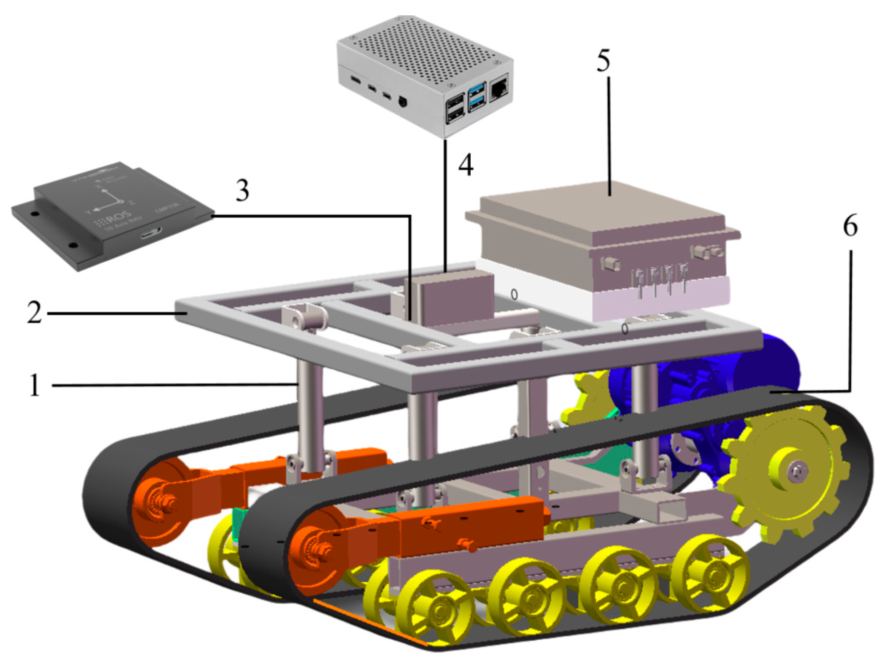
Based on the aforementioned requirements, the designed hilly and mountainous tracked operational chassis primarily comprises a tracked driving system, a hydraulic leveling system, a control system, and a leveling platform. The overall structure is shown in Figure 1.
The leveling system employs a four-point lifting scheme, which achieves active leveling of the platform on lateral slopes by controlling the extension and retraction of four hydraulic actuators. The main technical parameters of the chassis are summarized in Table 1.

2.2. Stability Analysis

For hilly and mountainous chassis operating on slopes, the leveling system essentially functions as an active rollover prevention system. Its stability directly dictates the safety and reliability of operations. In this study, the anti-rollover stability is analyzed by establishing a static mechanical model of the chassis.

2.2.1. Master Controller

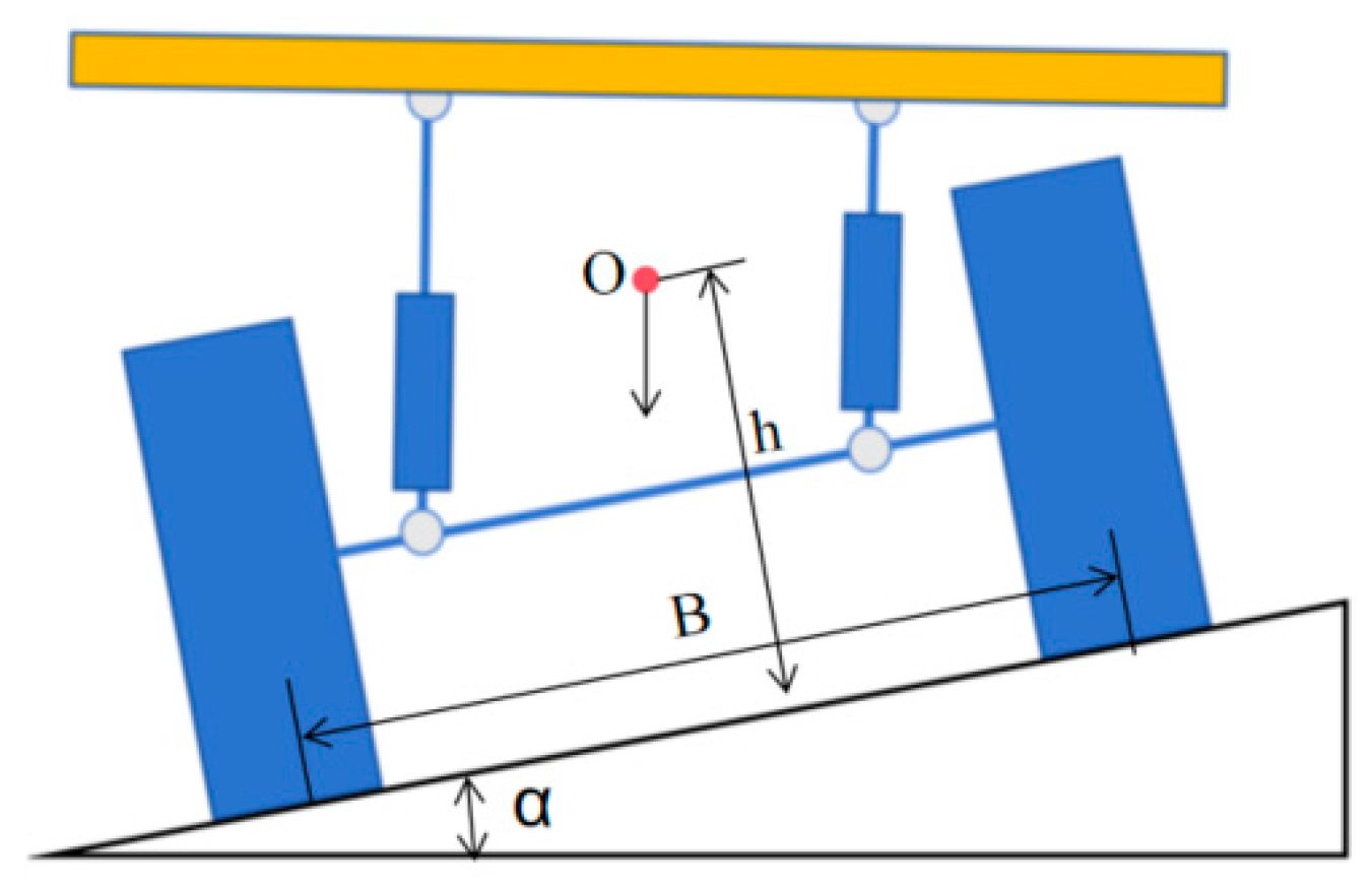
The stability of the chassis on lateral slopes is primarily determined by the position of the center of gravity (Point O) relative to the track grounding profile (support polygon). As shown in Figure 2, when the chassis experiences lateral tilting, the overall center of gravity shifts accordingly. The critical condition for preventing chassis rollover is that the projection of the center of gravity must remain within the track support area.
Taking the lateral stability analysis as an example, assuming the total machine mass is M, the vertical height of the center of gravity from the ground is h, and the distance between the centers of the two tracks is B. When the chassis is stationary on a transverse slope with an inclination angle α , the anti-rollover stability moment M s and the rollover moment M r can be expressed as follows:
M s = M g × B 2 × cos α
M r = M g × h × sin α
When M s > M r , the chassis maintains stability. The critical rollover angle α m a x can be derived from the moment equilibrium equation as follows:
M g × B 2 × cos α m a x = M g × h × sin α m a x
which simplifies to the following:
α m a x = arctan B 2 h

2.2.2. Enhancement of Stability by the Leveling System

The leveling system developed in this study actively adjusts the platform attitude to maintain horizontality while operating on slopes. This process is functionally equivalent to pulling the elevated center of gravity—caused by the slope—back toward the uphill side, thereby reducing the lever arm of the rollover moment Mr and significantly increasing the critical rollover angle α max.
Based on the design parameters specified in Section 2.1, the track gauge B measures 520 mm. Theoretical calculations reveal that the critical lateral rollover angle of the chassis in its unleveled state is α static. When the leveling system is activated and restores the platform to a horizontal position, the effective center-of-gravity height h is reduced, thereby yielding a significantly larger dynamic critical rollover angle α level. Both simulation and theoretical calculations demonstrate that α level substantially exceeds α static and fully covers the system’s maximum leveling angle of 22.3°. This indicates that, within the designed leveling range, the system not only maintains platform horizontality but also proactively ensures overall vehicle stability, fundamentally preventing rollover incidents.
In summary, the lifting-type leveling mechanism elevates the vehicle frame during operation, thereby shifting the overall center of gravity upward along the slope. This motion effectively reduces lateral sway and roll sensation of the tracked chassis, consequently enhancing the vehicle’s rollover resistance. By incorporating active posture control, the proposed system inherently prioritizes stability as a core design objective, thereby establishing a safety-oriented foundation for the development of subsequent control strategies and algorithms.

2.3. Leveling Operational Principle

The tracked operational chassis features a longer overall length compared to its width, providing greater structural space for longitudinal arrangements. Consequently, the leveling system achieves a larger leveling angle in the longitudinal direction than in the lateral direction. Specifically, the system designed in this study enables a lateral leveling capability of 22.3°.
The chassis propulsion system is controlled independently via remote operation, while the leveling platform is regulated by a hydraulic lifting mechanism. An inclination sensor, fixed on the upper surface of the vehicle frame with its longitudinal axis aligned with the platform’s y-axis, continuously monitors the vehicle’s attitude. The upper and lower ends of the hydraulic push rods are hingedly connected to the tracked traveling mechanism and the platform frame, respectively.
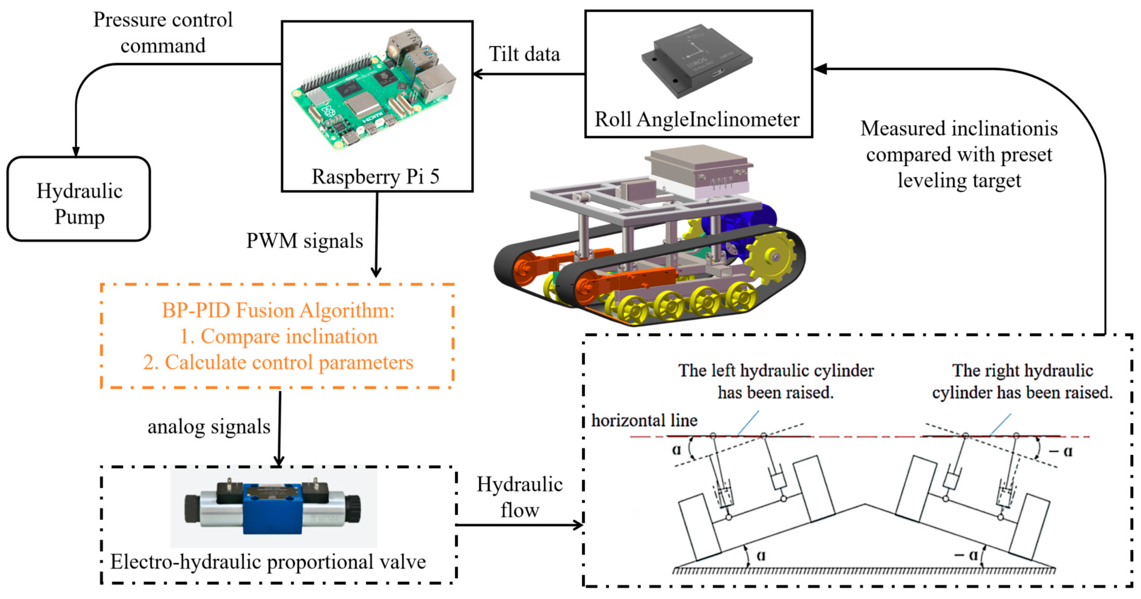
When the sensor detects platform tilt, it sends a signal to the controller. The leveling system then actuates the corresponding hydraulic push rods to extend or retract, as illustrated in Figure 3. This action causes the entire frame to rotate about its pivot axis, while the push rods on the opposite side remain retracted. This unilateral lifting continues until the platform reaches a horizontal orientation, at which point the control process terminates.
As illustrated in Figure 3, transverse chassis inclination triggers real-time detection by the roll angle inclinometer. The sensor acquires tilt status with a resolution of ±0.1° and transmits digitized data to the main control unit (Raspberry Pi 5) for error quantification.
The Raspberry Pi 5 executes the following control sequence:
  • Error Calculation: Compares the measured inclination angle with the preset leveling target value.
  • Algorithm Execution: Implements the BP-PID fusion control algorithm to generate optimized control parameters.
  • Signal Conversion: Generates PWM signals for the electro-hydraulic proportional valves. Converts digital PWM signals to analog through a power amplifier.
  • Flow Regulation: Modulates hydraulic flow rates via the proportional valves based on the amplified control signals.
This coordinated control action drives precise extension/retraction of the hydraulic cylinders, progressively reducing the displacement differential (Δh) between lateral support points. Using left-side leveling as the representative case, the following holds:
Δ h = W tan α
where:
Δ h —Vertical Displacement Difference, mm.
W   —Transverse Platform Length, mm.
α —Ground Slope Angle, °.
Based on geometric relationships, the functional correlation between cylinder stroke length S and tilt angle α can be derived as follows:
S 2 = 2 L 2 + M 2 2 L L 2 + M 2 cos ( α 0 + α )
σ = arccos L sin α + M S
where:
S —Instantaneous length of the hydraulic cylinder, mm.
L   —Horizontal center-to-center distance between transverse cylinders, mm.
M —Initial length of the hydraulic cylinder (fully retracted state), mm.
α 0 —Initial mounting angle between hydraulic cylinder and locomotion unit, °.
σ   —Angular displacement of the hydraulic cylinder during leveling, °.

3. Design of Automatic Leveling Control System

3.1. Hardware Design of Control System

The hardware architecture of the control system forms the foundational infrastructure and performance guarantor for the automatic leveling system in hilly/mountainous agricultural machinery. Core components—including high-precision inclinometers, high-performance controllers, and high-torque actuators—directly determine the system’s measurement accuracy, computational real-time performance, and leveling load capacity. Concurrently, IP67-rated enclosures, extended operational temperature range, and interference immunity design (e.g., CAN bus isolation) ensure operational reliability under harsh field conditions.

3.1.1. Core Hardware Components

The system employs a Raspberry Pi as the master controller, chosen for its compact design and high-performance quad-core Cortex-A72 processor, which supports real-time execution of complex algorithms such as BP neural networks. Its versatile interfaces (GPIO/CSI/DSI) enable multi-sensor integration, including 6-axis IMUs. For attitude sensing, the JY901B inclinometer (Table 2) provides ±0.1° static accuracy and 100 Hz update rates, with robust environmental suitability (IP67 rating, −40 to 85 °C operating range) essential for harsh hilly terrain. These components collectively establish the sensing and processing foundation for precise leveling control.

3.1.2. Position Limit Switch

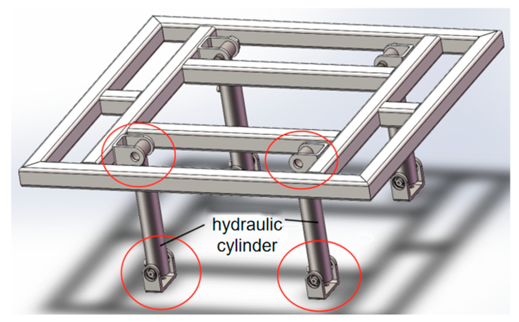
As illustrated in Figure 4, simultaneous extension of dual hydraulic cylinders creates an unstable parallelogram linkage in the leveling mechanism, inducing lateral instability due to loss of structural determinacy. To enforce kinematic stability, one actuator must remain fully retracted and constrained within the U-channel base, establishing a fixed pivot point.
Consequently, limit switches are integrated to verify hydraulic actuator retraction to this mechanical datum, preventing unsafe configurations while enhancing system reliability under high-frequency leveling cycles (>2 Hz). To eliminate field vibration-induced false triggering—particularly under ISO 5008 [19]: 2002-defined PSD-random vibration exceeding 0.04 g2/Hz—Omron V-15 micro switches with roller-lever mechanisms were implemented. Their torsion spring-assisted reset maintains dynamic equilibrium according to the following:
τ v < K t θ max K t = 0.45
where:
K t —Spring torque constant, N·m/rad.
θ max —The lever angular tolerance, N.
τ v —The interference torque caused by vibration, N·m.
θ max = 15° is the lever angular tolerance, ensuring immunity to shocks up to 15 g. Field validation confirmed zero false triggers during 200 km traversals on Class C terrain while achieving 1.2 × 10⁶ operational cycles without mechanical failure.

3.2. Design of Dual-Layer Threshold Intelligent Control Strategy

In automatic leveling mode, the tracked chassis achieves real-time autonomous leveling in response to road slope variations. The performance of this system is fundamentally governed by its control strategy.
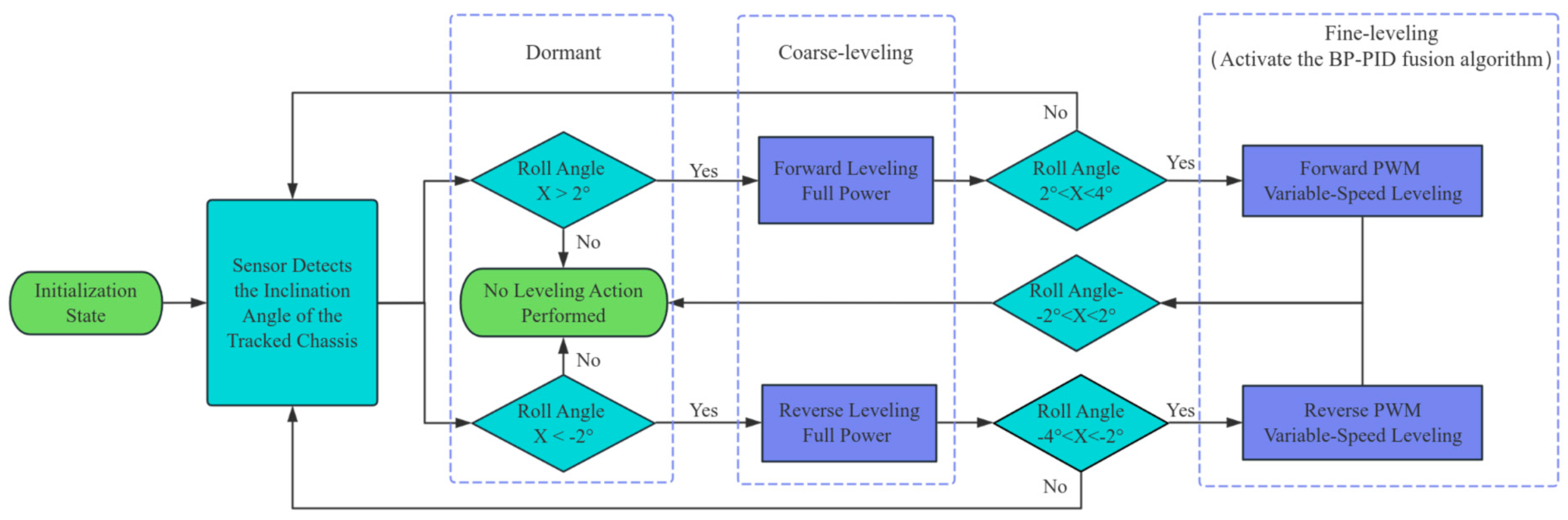
To address the dynamic working conditions of hilly and mountainous terrain, this control system employs a dual-layer threshold strategy, developed as an improvement over conventional dual-threshold methods [24]. Traditional dual-threshold approaches typically assign the lower threshold as an “activation threshold” and the higher threshold as a “target level,” thereby categorizing execution actions into two simple types: those outside and inside the threshold range. In contrast, the proposed strategy intelligently classifies the leveling process into three distinct modes—“Coarse-leveling”, “Fine-leveling,” and “Dormant”—based on threshold layering, tailored to the specific demands of dynamic operations in undulating terrain. The intelligent selection mechanism for these modes is illustrated in Figure 5.

3.2.1. “Dormant” Control Strategy for Level Terrain

To minimize unnecessary energy consumption and mechanical wear caused by frequent activation due to inherent chassis vibration or minor bumps on level ground, the system implements a “Dormant” control strategy under such conditions, suspending leveling operations.

3.2.2. Determination of the Inner-Layer Threshold

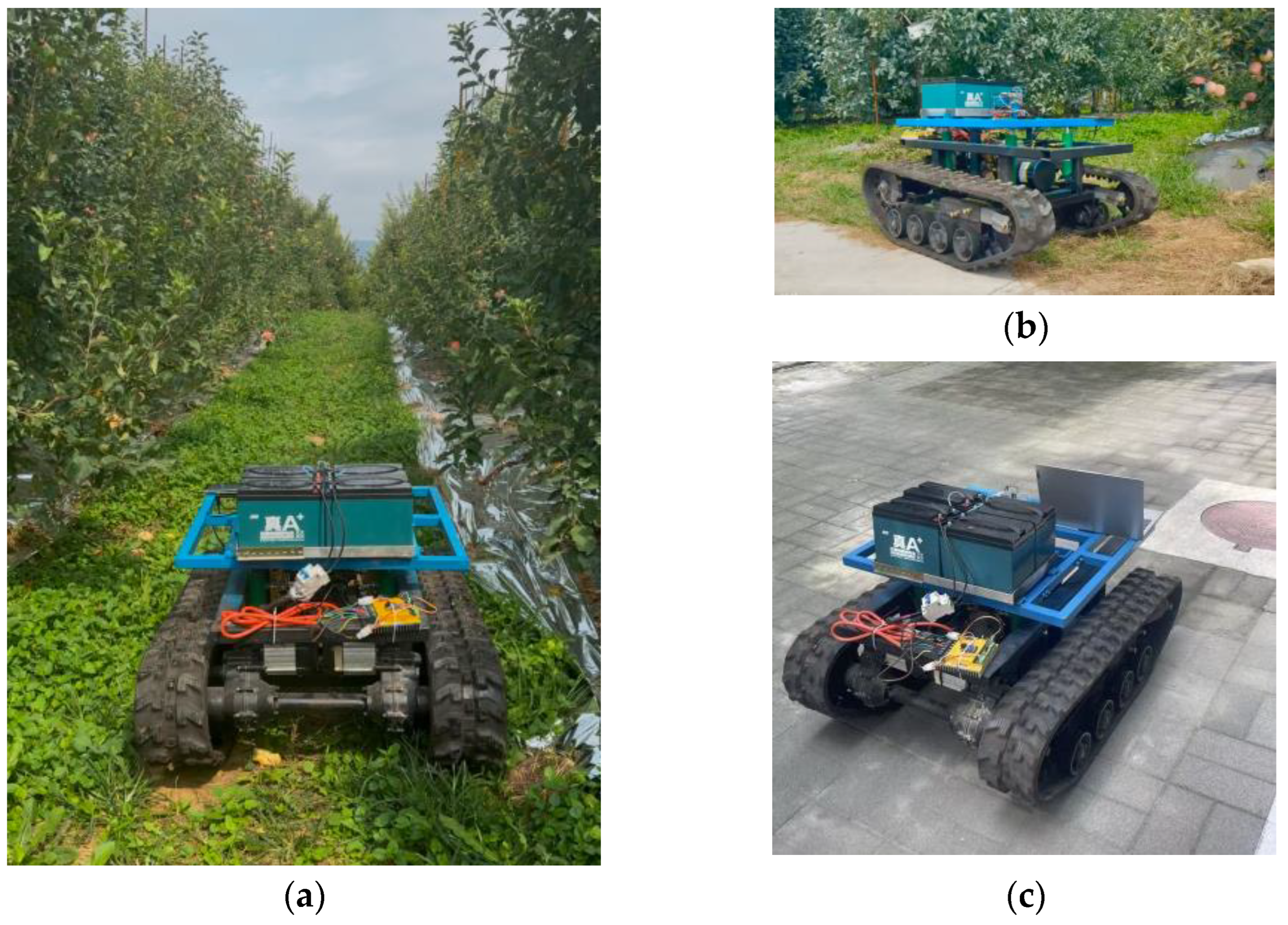
To determine the inner-layer threshold for the “Dormant” state, field tests were conducted using the prototype tracked chassis. With the automatic leveling function deactivated and both hydraulic push rods retracted to their lowest balanced position, under the standard 50 kg operational load, the prototype was driven at constant speeds of 3 km/h and 5 km/h for 120 s on three distinct types of level roads. The test site is illustrated in Figure 6.
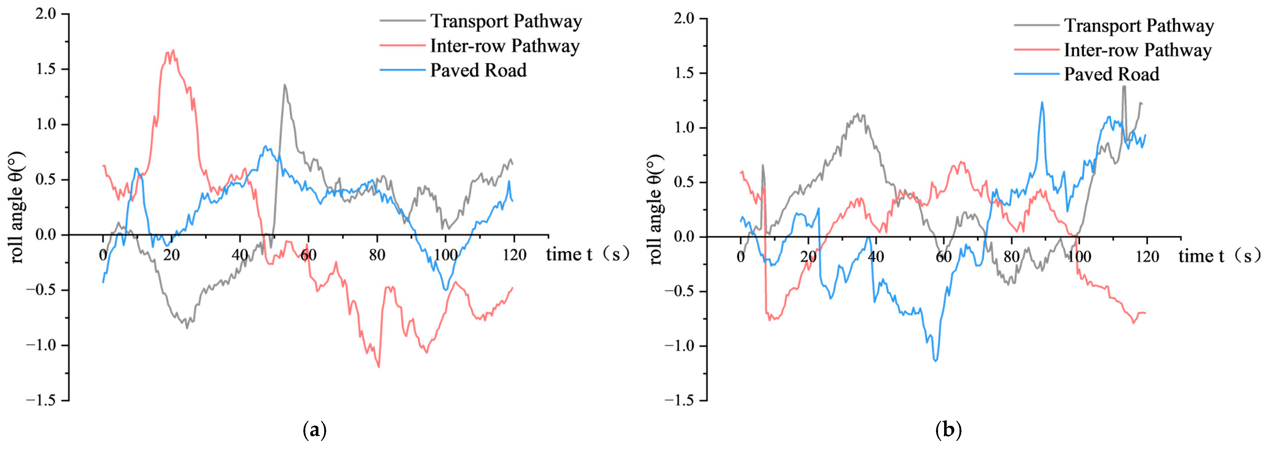
During these tests, roll angle data were recorded using the attitude sensor, with the acquired dataset presented in Figure 7.
Based on the collected data, the maximum absolute roll angle value measured during the chassis’s operation in orchard inter-row pathways, field transport roads, and paved roads was θ = 1.875°. Consequently, the inner-layer threshold was established at θi = 2.0°. Leveling actions are not triggered when the detected roll angle remains below this value.

3.2.3. “Coarse-Leveling” and “Fine-Leveling” Strategies for Slope Conditions

When the system detects an absolute roll angle exceeding the 2.0° inner threshold, it identifies a slope condition and immediately initiates the angle deviation control strategy for leveling.
To optimize both leveling efficiency and precision on slopes, an outer-layer threshold is introduced, differentiating between “Coarse-leveling” and “Fine-leveling” phases. The “Coarse-leveling” phase employs full-power output to the electro-hydraulic proportional valve, rapidly reducing the roll angle to within the outer threshold, thus prioritizing speed. Subsequently, the “Fine-leveling” phase engages a fused BP neural network and PID control algorithm to achieve high-precision control of the proportional valve for final adjustment.

3.2.4. Determination of the Outer-Layer Threshold

The outer threshold is a critical parameter dictating the transition from the high-efficiency “Coarse-leveling” mode to the high-precision “Fine-leveling” mode. To optimize performance by minimizing leveling time while constraining overshoot, the optimal value was determined experimentally.
With the inner-layer threshold fixed at 2.0°, leveling tests under the same 50 kg load were conducted on slopes of 20° and 10° using a set of candidate values for the outer-layer threshold: θ o = 7.0°, 6.0°, 5.0°, 4.0°, and 3.0°. For each candidate value, the leveling control system was activated on both the 20° and 10° slopes, and real-time roll angle data were collected. The leveling time T (s)—defined as the duration from the initiation to the completion of the leveling action—and the maximum overshoot θ v (°)—the maximum absolute reverse deviation of the inclination angle from the desired steady-state value during the process—were recorded.The test results are shown in Table 3.
The results indicate that as θ o decreased from 7.0° to 4.0°, leveling time shortened significantly. This is attributed to the “Coarse-leveling” mode correcting a larger portion of the deviation before switching. However, further reduction to θ o = 3.0° increased leveling time due to excessive kinetic energy from prolonged full-power operation, causing significant overshoot that required additional time for the “Fine-leveling” mode to correct.
In summary, the selection of the outer threshold inherently represents a trade-off between efficiency and stability. An excessively high threshold, while minimizing overshoot, results in inefficient performance due to the premature engagement of the fine-leveling mode. Conversely, an excessively low threshold introduces significant overshoot, which compromises both system stability and operational efficiency. Within the experimental framework of this study, θ o = 4.0° was identified as the optimum. This value allows for the full utilization of the coarse-leveling mode’s rapid response, while ensuring a timely transition to the fine-leveling mode before system inertia induces substantial overshoot. This strategy yielded the shortest average leveling time (T = 4.2 s) while maintaining the overshoot within an acceptable limit ( θ v < 1.0°). Consequently, 4.0° was selected as the outer threshold for the system.

3.3. “Lower-First Then Raise” Control Strategy

While the angle deviation and dual-layer threshold control strategies effectively enable the leveling function of the tracked chassis, an unstable parallelogram configuration can form between the hydraulic cylinders and the platform frame during actuator movement. To ensure platform stability, the leveling action is therefore optimized into a “Lower-First Then Raise” control strategy.
Limit switches are installed beneath the U-shaped grooves of the support base on both sides. These switches detect whether the pivot shaft of the single-side platform frame is constrained at its lowest point within the base, thereby guaranteeing structural stability during the leveling process.
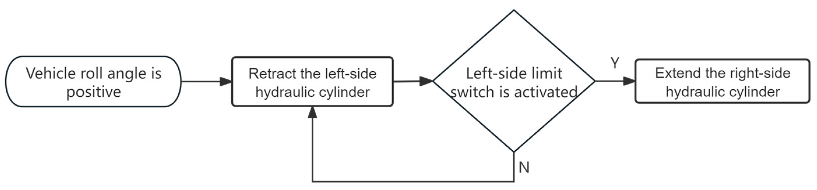
Taking a positive leveling action (triggered by a detected positive roll angle) as an example, the hydraulic cylinders on both sides execute the “Lower-First Then Raise” strategy according to the sequence outlined in Figure 8. This procedure ensures a stable and controlled leveling operation.

4. Optimization and Simulation of Chassis Control Algorithms

To enhance the leveling performance of the tracked chassis, the control algorithms were designed and optimized using the established control strategy. A hydraulic system model of the chassis was constructed based on AMEsim, and a leveling system controller was developed in Simulink for subsequent simulation analysis.

4.1. Hydraulic System Model Construction

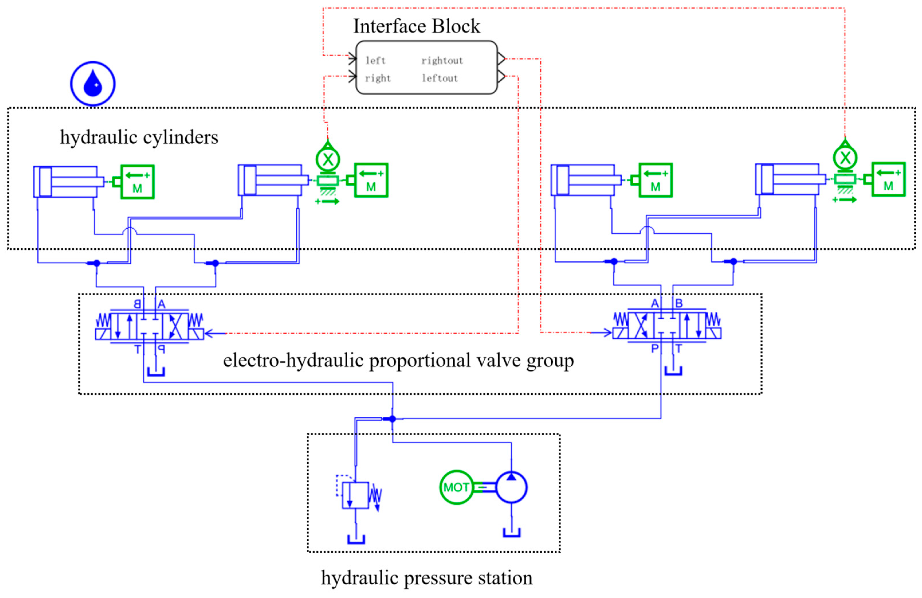
The hydraulic leveling system primarily comprises components including a fuel tank, safety valve, hydraulic pump, electric motor, pressure-stabilizing valve, on–off valve, proportional directional control valve, and hydraulic cylinders. The hydraulic principle operates as follows: the dual hydraulic push rods on each side are connected via a synchronizing valve to ensure simultaneous extension and retraction. The leveling system regulates the inflow and outflow of hydraulic oil to the cylinders through the proportional directional control valve. A positive control current directs pressurized oil into the hydraulic cylinder, while a negative current reverses the flow direction. Each hydraulic cylinder’s circuit is controlled by an on–off valve.
Specifically, when oil is supplied to the left rodless cavity and the right rod cavity, and simultaneously drained from the left rod cavity and the right rodless cavity, the left side of the chassis elevates. The reverse process raises the right side.
Based on the operational principle of the hydraulic leveling system for the hilly and mountainous tracked chassis and the experimental platform for body posture leveling, a hydraulic system simulation model was established within AMEsim. In this model, the four leveling hydraulic cylinders in the simulation correspond to the left-front, left-rear, right-front, and right-rear leveling positions on the simulated tractor body. An Interface Block module was created for interfacing with Simulink to facilitate co-simulation analysis. The co-simulation hydraulic model is illustrated in Figure 9. The system uses the fuselage inclination angle as the input and outputs control signals to command the two proportional solenoids, enabling leveling simulation analysis on lateral slopes.
Following model establishment, appropriate mathematical models were selected for each component in the submodel mode. Parameters for these mathematical models were then configured according to the specific parameters of each hydraulic component in the chassis, such as applying the static gravitational load of the chassis through the hydraulic cylinder module and setting the dynamic inertial load of the chassis using an external force application module. The key parameters are listed in Table 4 below.

4.2. PID Control Algorithm Modeling

To ensure high-precision adjustment capability in the chassis leveling system, this study integrates PID control with a BP neural network-based algorithm. A comparative analysis was conducted between the PID controller and the BP neural network-based adaptive PID controller to evaluate their respective leveling performance characteristics.
Based on the PID control principle, a dedicated PID control algorithm was developed for attitude leveling of the tracked chassis operating in hilly and mountainous terrain. Its control output is given by the following:
Δ u k = K p e k e k 1 + K i e k + K d e k 2 e k 1 + e k 2
u k —Control variable.
e k = r k y k —System error.
K p —Proportional gain.
K i —Integral gain.
K d —Derivative gain.
A PID control algorithm was implemented in MATLAB2024b/Simulink, with the simulation model shown in Figure 10. The PID parameters were set to K p = 10, K i = 5, and K d = 2. The output values from the synchronous control algorithm for same-side cylinders were used to make online adjustments to the PID output. These final values were then sent to the AMESim controller module to regulate the spool movement of the electro-hydraulic proportional valve, thereby executing the leveling action through hydraulic cylinder adjustment.

4.3. Self-Adaptive PID Control Algorithm Based on BP Neural Network

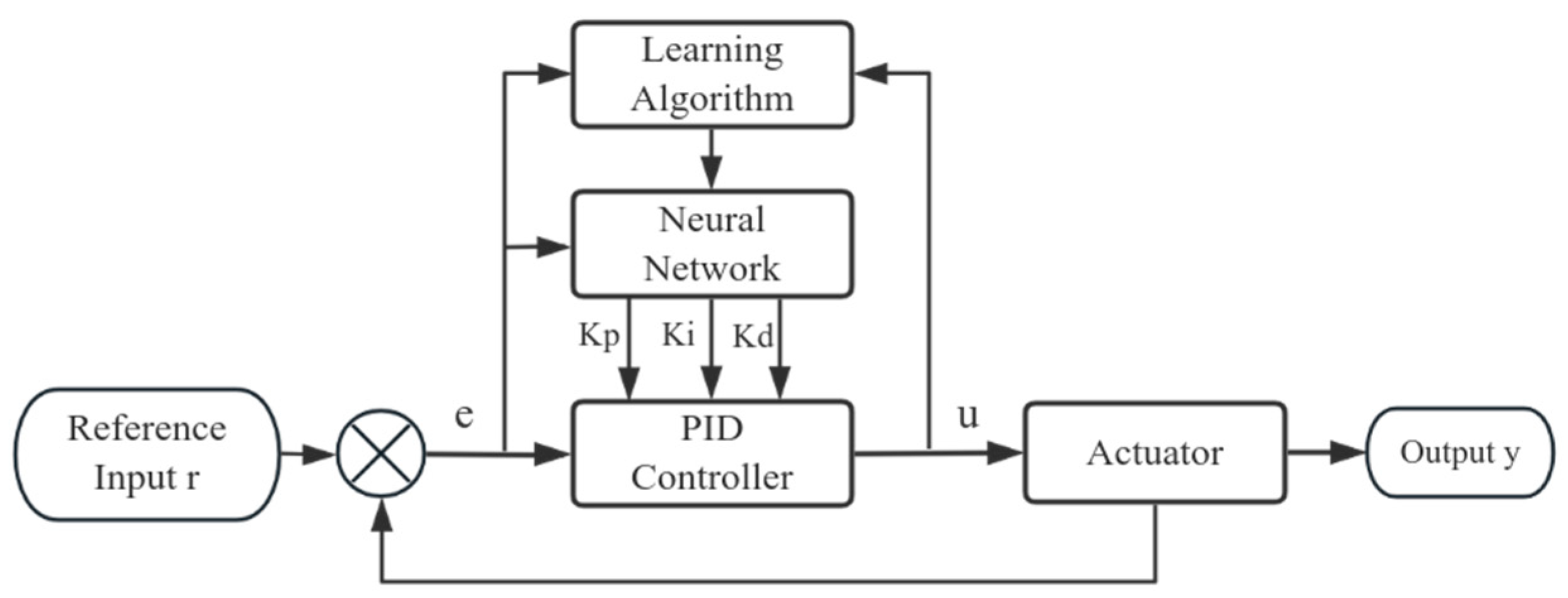
The proportional, integral, and derivative parameters in PID control exhibit interdependent and mutually constraining characteristics. Leveraging the ability of BP networks to approximate nonlinear functions enables the self-learning of optimal combinations of these three parameters. Figure 11 shows the closed-loop block diagram of the BP neural network-based PID controller.
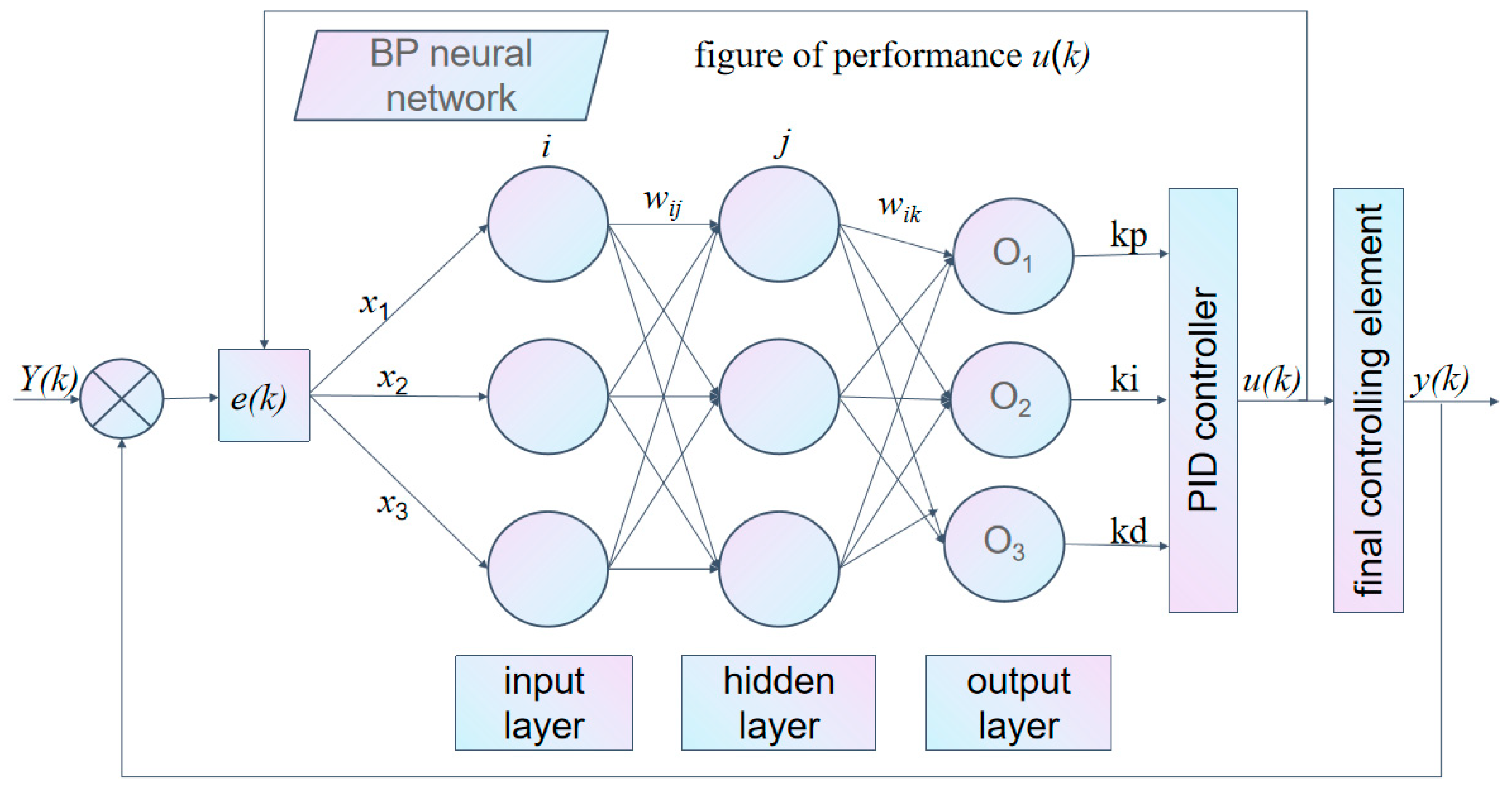
The controller comprises two main components: a conventional PID controller, which provides closed-loop feedback control of the plant, and a neural network, which dynamically adjusts the PID parameters based on system states and specific learning algorithms to achieve optimal performance. The structure of the neural network used in this controller is shown in Figure 12. The design procedure is outlined as follows:

4.3.1. Determining the Structure of the BP Neural Network

The number of nodes in the input layer (M), the number of nodes in the hidden layer (Q), and the number of hidden layers themselves should be minimized to reduce system complexity and shorten learning time. The number of neurons in the input and output layers depends on the specific application. For the PID controller, the neural network output layer contains three nodes, corresponding to the three PID parameters K p , K i , and K d . The hidden layer serves to extract features from the input signals. While increasing the number of hidden layers can enhance network capability in applications like image processing, one or two hidden layers are typically sufficient for PID control applications.

4.3.2. Network Implementation Details: Structure and Training

To ensure the reproducibility and clarity of the proposed adaptive PID controller, the detailed structure, parameters, and training process of the employed BP neural network are specified as follows.
A three-layer feedforward structure, denoted as 3-6-3, is adopted for the BP neural network. This configuration comprises:
Input Layer (M = 3): Three nodes that receive the system error and its recent history: x = e k , e k 1 , e k 2 , where e k = r k y k is the roll angle error at the k-th sampling instant.
Hidden Layer (Q = 6): Six neurons. This number was determined empirically to balance model complexity and computational efficiency on the Raspberry Pi platform, providing sufficient nonlinear approximation capability without overfitting.
Output Layer (3 nodes): Corresponding to the three adjustable parameters of the PID controller: O ^ = K p , K i , K d .
Selection of Activation Functions:
Using the Sigmoid function as the activation function can lead to minimal weight modifications when neurons operate in the saturated regions of the curve (where the gradient is small), significantly slowing the learning process.
Considering the nonlinear characteristics of the dynamic leveling process in hilly terrain, the hyperbolic tangent function (tanh) was selected for the hidden layer due to its symmetry, which aids in accelerating convergence.
O i 2 = f n e t i 2 = tanh ( n e t i 2 ) = e n e t i 2 e t e x t n e t i 2 e n e t i 2 + e n e t i 2   i = 1 , 2 , , Q
Its derivative is as follows:
d d n e t tanh ( n e t ) = 1 tanh 2 ( n e t ) = 1 ( O 2 ) 2
Because the output layer nodes correspond to K p , K i , K d , which must be non-negative, a non-negative version of the tanh function is applied as the activation function for this layer.
O l 3 = g n e t l 3 = 1 2 1 + tanh ( n e t l 3 ) = e n e t l 3 e n e t l 3 + e n e t l 3 l = 1 , 2 , 3
Its derivative is as follows:
g n e t l 3 = 2 g n e t l 3 1 g n e t l 3 = 2 O l 3 1 O l 3
The initial connection weights w i j 2 (from input to hidden layer) and w i j 3 (from hidden to output layer) were randomly assigned small values within the range [−0.5, 0.5].
Learning Rate: An excessively high learning rate tends to induce oscillations during training and compromises robustness, whereas an excessively low rate significantly slows convergence. Therefore, through experimental tuning, the learning rate was set to η = 0.2.
Training Mechanism: The performance index function E k = 1 2 ( r k y k ) 2 (Equation (21), defined later) is formulated according to the neural network learning paradigm to guide the adjustment of weighting coefficients and drive the reduction in the fuselage inclination control error. The network performs online learning via the gradient descent rule, adjusting weights in real time.
Offline Pre-training: Prior to deployment, the network was also pre-trained for 1000 iterations offline using simulated data representing typical slope leveling scenarios. This process initializes the weights to a favorable starting point, enhancing the initial performance and convergence speed of the online controller.

4.3.3. Control Algorithm Calculation Procedure

Based on the aforementioned network design, the online calculation procedure of the adaptive PID control algorithm is as follows.
The system setpoint r k and actual output y k at the current sampling time k are acquired. The error e k , along with the inputs and outputs of the network’s input layer, hidden layer, and output layer, are then computed sequentially.
The output of the input layer is as follows:
O j = x j ,     j = 1 , 2 , , M
The input and output of the hidden layer are as follows:
n e t i 2 k = j = 1 M w i j 2 k O j 1 k
O i 2 = f n e t i 2 ,   i = 1 , 2 , , Q
The input and output of the output layer (i.e., the PID parameters) are as follows:
n e t l 3 k = i = 1 Q w l i 3 k O i 2 k
O l 3 k = g n e t l 3 k ,     l = 1 , 2 , 3
Here, O 1 3 = K p , O 2 3 = K i , O 3 3 = K d .
According to the incremental PID algorithm, the controller output is calculated as follows:
u k = u k 1 + Δ u k
Δ u k = K p e k e k 1 + K i e k + K d e k 2 e k 1 + e k 2
Here, u k is the voltage control signal for the proportional directional valve at time k ;   u k 1 is the voltage control signal at time k 1 ; e k , e k 1 , e k 2 are the control errors between the desired and actual fuselage roll angles at time k , k 1 , and k 2 , respectively.
Backpropagation for Weight Adjustment (Online Learning): To guide the weight adjustment and drive the reduction in the fuselage inclination control error, the performance index function, formulated according to the neural network learning paradigm, is introduced as follows:
E k = 1 2 ( r k y k ) 2 = 1 2 e r r ( k ) 2
where r k denotes the desired fuselage inclination input and y k represents the actual fuselage inclination output.
The connection weights are adjusted based on the gradient descent rule. Given the learning rate η, the adjustment amount for the output layer connection weights w l i 3 is calculated as follows:
Δ w l i 3 k = η E k w l i 3 k
Applying the chain rule and leveraging Equations (13) and (18), this simplifies to the following:
Δ w l i 3 k = η δ l 3 O i 2 k
δ l 3 = e r r k s g n y k u k Δ u k O l 3 g n e t l 3 k l = 1 , 2 , 3
Here, y k u k can be estimated using the system model or approximated as 1, and Δ u k O l 3 is readily derived from Equation (20).
The output layer connection weights at time k are updated as follows:
w l i 3 k = w l i 3 k 1 + Δ w l i 3 k
Similarly, the adjustment for the hidden layer connection weights w i j 2 , derived accordingly, is calculated as follows:
Δ w i j 2 k = η E k w i j 2 k
Δ w i j 2 k = η δ i 2 O j 1 k
where f n e t i 2 k is calculated using Equation (11).
The hidden layer connection weights at time k are updated as follows:
δ i 2 = f n e t i 2 k l = 1 3 δ l 3 w l i 3 k i = 1 , 2 , , Q
As demonstrated by the foregoing derivation, during the leveling control process, any discrepancy between the actual fuselage inclination angle θ and the desired angle θ0 triggers automatic, real-time adjustments to the weighting coefficients across all neural layers according to Equations (23)–(28). These adjustments progressively reduce the output error E k and modify the outputs of the output layer, thereby enabling self-tuning of the PID parameters and consequently enhancing the overall leveling performance.

4.4. Neural Network Control Simulation Model

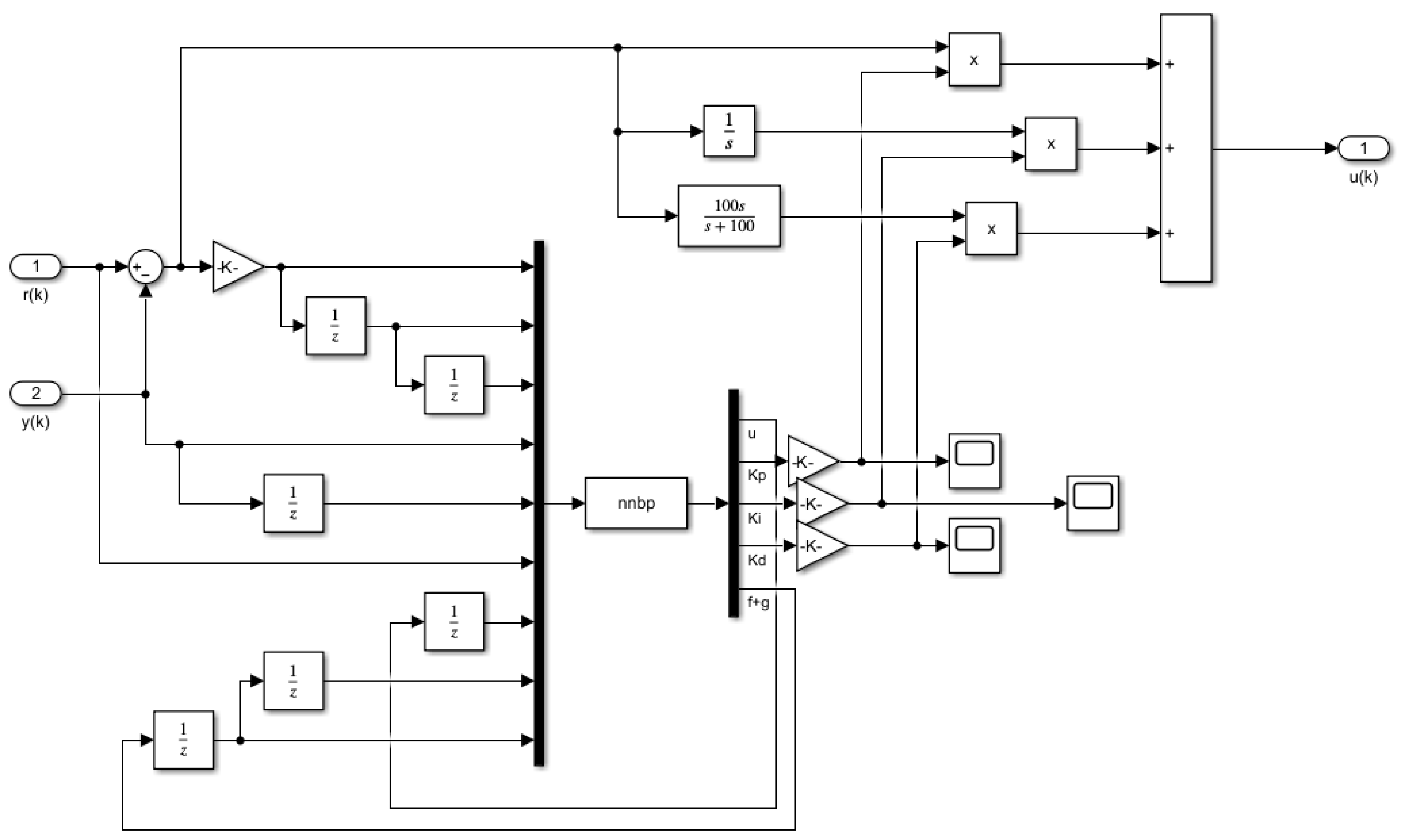
The simulation model is depicted in Figure 13. A self-adaptive PID controller based on a BP neural network was developed within the MATLAB/Simulink environment. During the simulation, the entire machine was under no-load conditions, with structural components such as the work platform treated as lightweight parts; consequently, the influence of external disturbances was neglected. The system outputs the actual lateral inclination angle y(k). This value is compared with the desired lateral inclination angle r(k) to obtain the lateral/longitudinal inclination error e(k). This error signal is then fed into the BP neural network PID leveling controller.
The controller executes its control program and dynamically outputs parameters for the three nodes ( K p , K i , K d ). These parameters are used to generate voltage signals for the two proportional directional valves, regulating the valve port flow rates. These signals are consequently transformed into displacement control signals for the hydraulic cylinders. The hydraulic cylinders then execute the leveling action, driving the fuselage inclination error toward 0°. This process completes the leveling of the tracked chassis frame.

4.5. Simulation Results: Analysis and Comparison

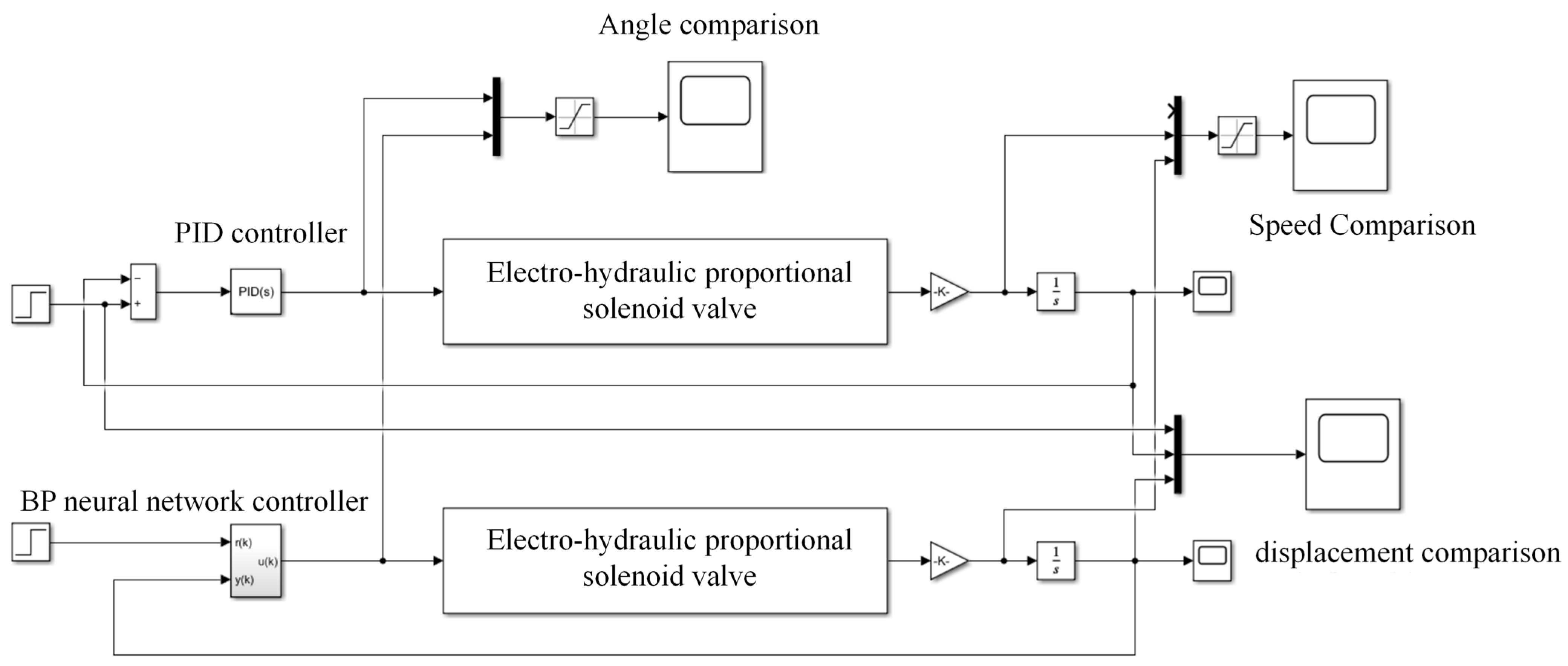
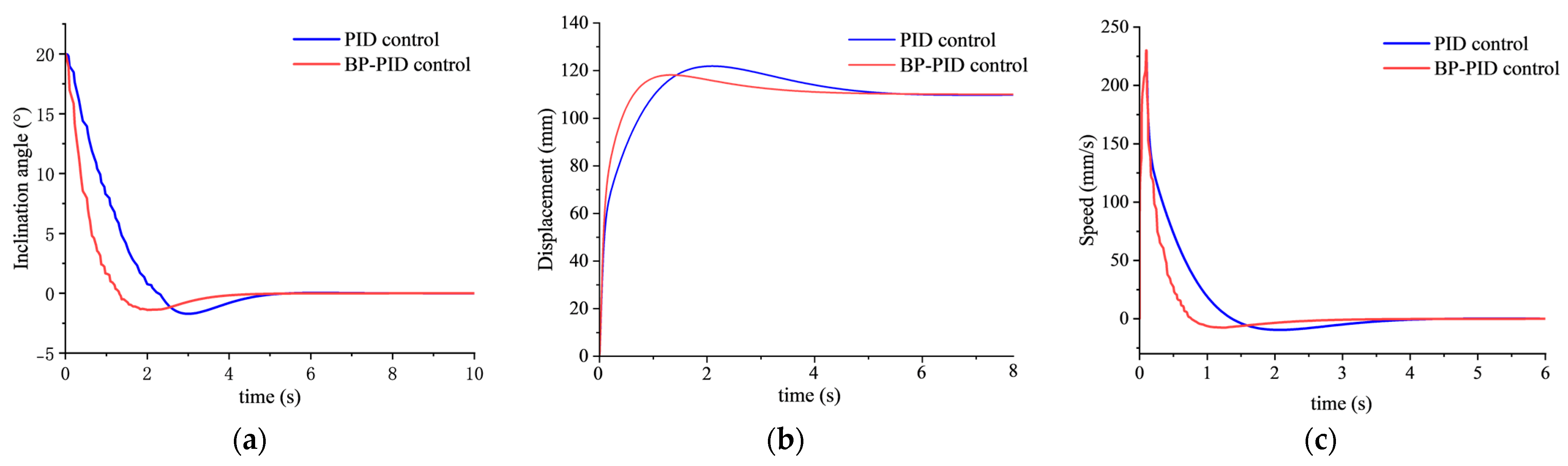
A comparative model integrating both a classical PID controller and the self-adaptive PID controller based on a BP neural network was established within the control framework (Figure 14). A comparative analysis of the leveling performance of these two controllers was subsequently conducted. To validate the effective leveling range of the system’s fuselage inclination angle adjustment, a leveling simulation was performed with the chassis initially positioned on a 20° slope, taking the right-side leveling as an example. The corresponding simulation results are presented in Figure 15.
As illustrated in Figure 15, the hydraulic actuator velocity increases rapidly at the initiation of the leveling process. Following a period of adjustment, it gradually decreases from its peak value and eventually stabilizes at zero upon completion of leveling.
Under PID control, the chassis leveling stabilization time is 3.8 s, with a maximum inclination overshoot of 3.1° and a steady-state error of 0.35°.
In contrast, the BP neural network PID control achieves a stabilization time of 2.5 s, a maximum inclination overshoot of 1.9°, and a steady-state error of 0.16°.
In summary, the simulation results demonstrate that for the hilly and mountainous tracked chassis under a 20° lateral slope scenario, the proposed BP neural network PID control outperforms the conventional PID control by reducing the stabilization time by 1.3 s (a 34.2% improvement) and the maximum overshoot by 0.7°. Furthermore, it enhances leveling accuracy by 36.8%, with the average leveling error consistently remaining within ±0.5°.
The superior performance of the BP-PID controller in simulations and experiments stems from its adaptive capability. While conventional PID parameters are fixed and struggle with nonlinear disturbances on hilly terrain, the BP neural network adjusts K p , K i and K d online based on real-time error, compensating for system dynamic variations and achieving a better balance between response speed and stability.

5. Field Experiments

5.1. Test Equipment and Setup

The tracked operational chassis measures 677 mm in height, 1188 mm in length, and 700 mm in width. It is powered by a 4 × 12 V 52 Ah lead–acid battery pack, which supplies energy to both the propulsion system and the leveling system, enabling a maximum operating travel speed of 5 km/h. All field tests were conducted under a typical operating load of 50 kg.
For attitude sensing, a JY901B attitude sensor is mounted above the leveling platform along the central axis of the chassis. This sensor provides a dynamic measurement accuracy of ±0.5° and monitors in real time the vehicle’s lateral tilt angle as well as the ground slope.
The control system centers on a Raspberry Pi 5 serving as the main control unit for the chassis. Its quad-core Cortex-A72 processor meets the computational demands of complex algorithms such as the BP neural network in real time. The system acquires sensor data via CSI/DSI interfaces, processes these data using the control algorithm, and subsequently transmits signals through a dedicated circuit to generate PWM voltage control signals for two high-precision electro-hydraulic proportional solenoid valves, thereby achieving dynamic leveling of the vehicle body.
To evaluate the operational performance of the leveling system for the tracked chassis under study, both static and dynamic tests were conducted on the prototype.
Static tests were performed on sloped terrain within the orchard. Manual leveling control was activated while the tilt sensor continuously monitored the vehicle’s attitude angle, thereby validating the fundamental leveling functionality.
Dynamic tests involved driving the prototype on a natural slope with a lateral inclination of 20. The prototype traveled at a speed of 3 km/h under automatic leveling mode. An onboard data logger recorded the vehicle’s attitude data for subsequent analysis of the slope leveling response.

5.2. Static Leveling Test

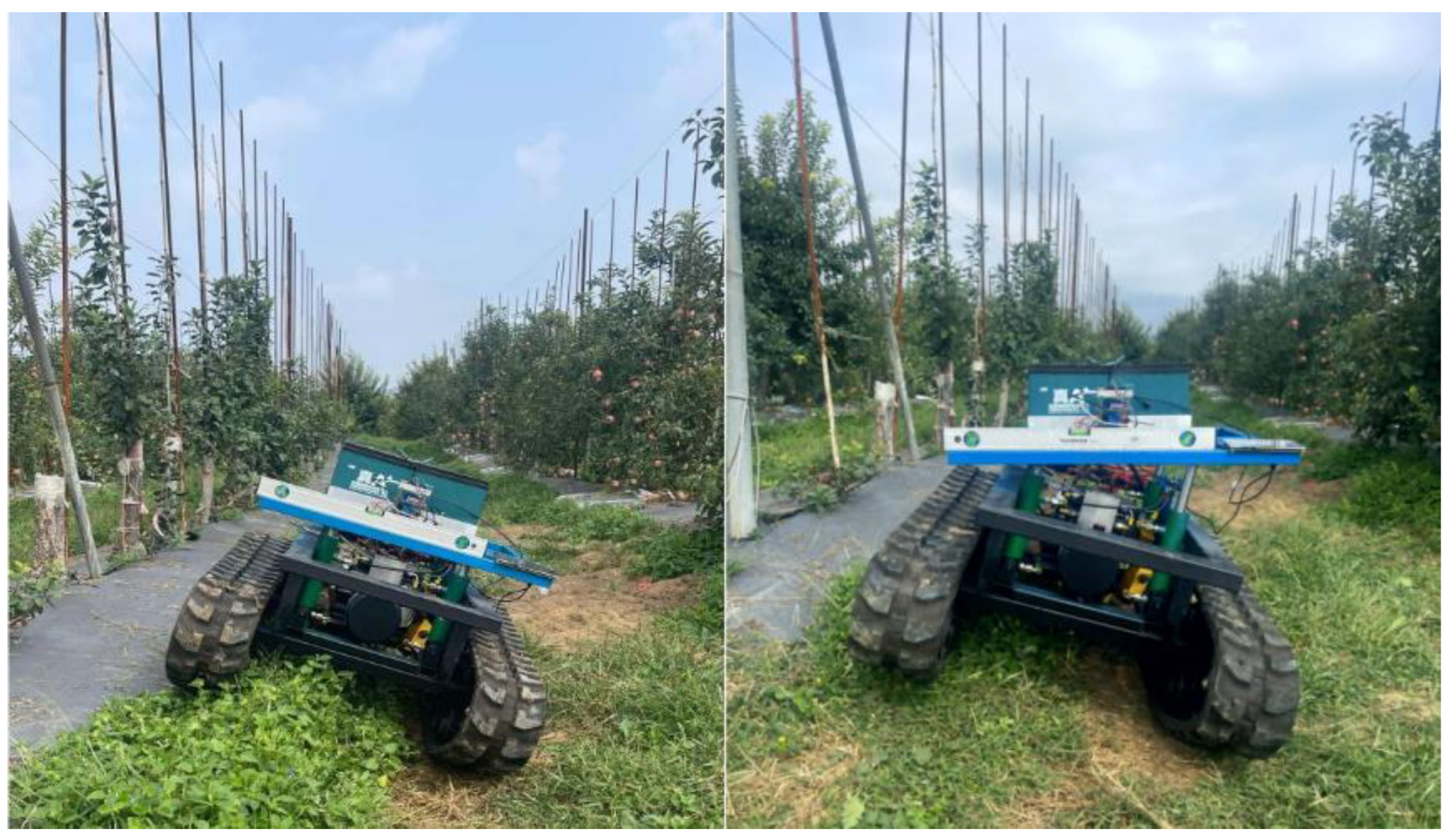
Static tests were conducted on sloped orchard terrain (Figure 16). The prototype was positioned on a 20° slope with its automatic leveling function deactivated. Following this, the leveling control system was manually initiated. Throughout the process, an inclination sensor continuously monitored the vehicle’s attitude angle. A comparative analysis was performed to evaluate the leveling accuracy and leveling speed between the PID and the BP neural network PID controllers under an identical dual-layer threshold strategy.
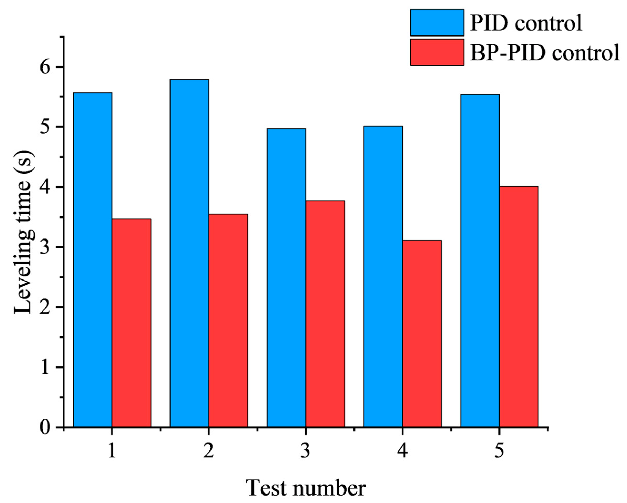
The JY901B inclination sensor was employed for real-time data acquisition throughout each trial, operating at a sampling frequency of 10 Hz. The leveling duration was defined as the period from the initial change to the stabilization of the attitude angle recorded by the sensor. Five trials were conducted for each control algorithm—the conventional PID and the BP neural network PID—to collect the leveling time for every individual process (Figure 17).
As illustrated in the corresponding figure, the BP neural network PID algorithm achieved an average leveling time of 3.6 s across the five trials. This represents a reduction of 1.7 s compared to the traditional PID controller. Furthermore, the overshoot remained below 0.5° in all cases. These results collectively demonstrate a high degree of repeatability and consistency, thereby validating the effectiveness and superior performance of the proposed system.

5.3. Dynamic Leveling Tests

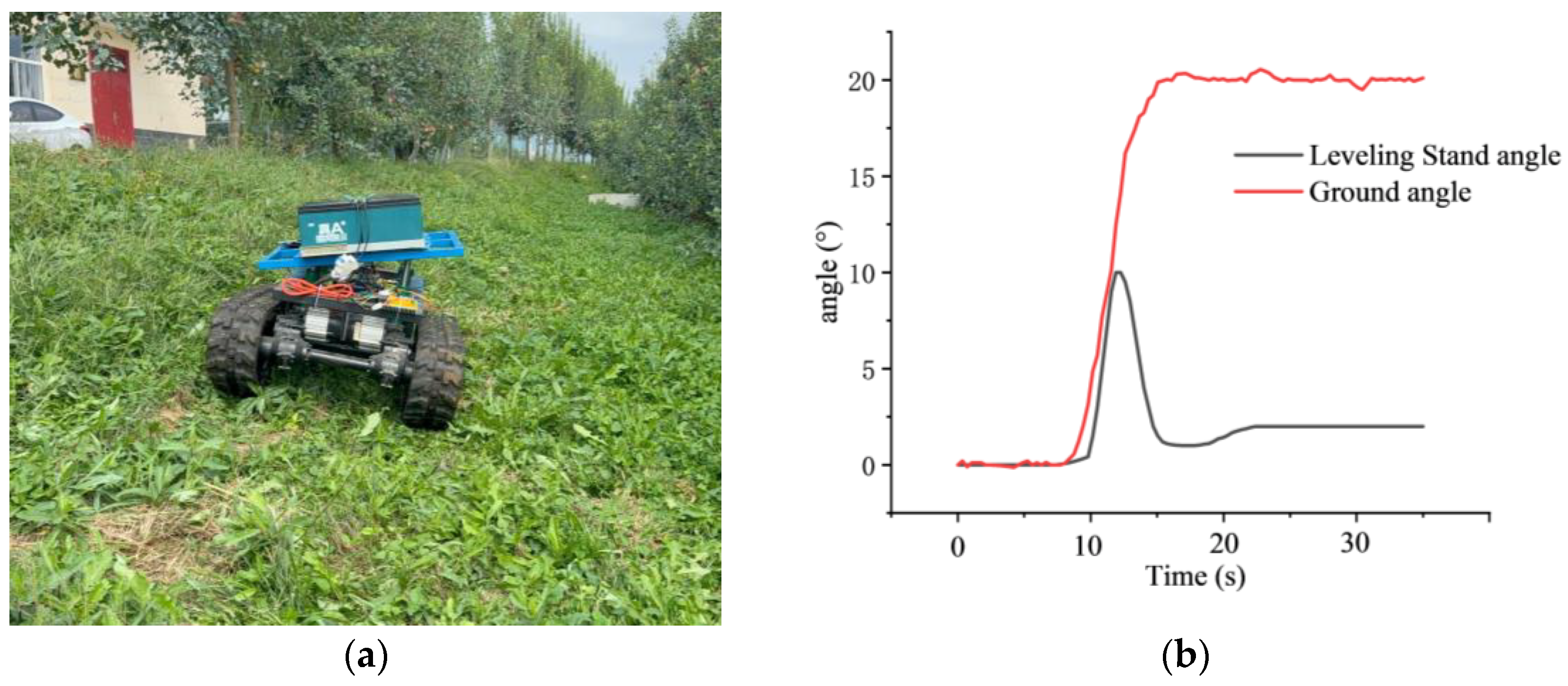
The dynamic tests were conducted on a transition from level ground to a natural lateral slope of approximately 20°. The prototype traversed this path at a speed of 3 km/h with the automatic leveling system activated. A vehicular data recorder, installed along the longitudinal axis of the tracked chassis, simultaneously recorded the real-time inclination of the ground and the leveling platform. The test site and the corresponding acquired data are presented in Figure 18.
Analysis of the field-acquired data confirmed the system’s dynamic performance. Upon detecting a slope with an absolute inclination exceeding the 2° threshold, the leveling system initiated the leveling action within 0.3 s. Conversely, the system correctly remained dormant when the chassis encountered road conditions with inclination angles below this 2° threshold, effectively preventing unnecessary actuation.

6. Conclusions

This study designed and evaluated a lateral leveling control system for tracked operation chassis in hilly and mountainous terrain which integrates a dual-layer threshold strategy with a BP neural network. The system’s leveling performance was rigorously assessed through co-simulation modeling and comprehensive field tests.
Simulation results demonstrate that under a 20° lateral slope condition, the BP neural network PID controller outperformed the conventional PID controller by reducing the stabilization time by 1.3 s (a 34.2% improvement) and the maximum inclination overshoot by 0.7°. Furthermore, leveling accuracy was enhanced by 36.8%, with the steady-state error consistently confined within ±0.5°.
Field trials validated that the dual-layer threshold strategy (4.0° outer layer, 2.0° inner layer) optimally balanced leveling speed with precision, effectively preventing spurious activations. The BP neural network PID algorithm significantly enhanced leveling stability on complex terrain through its dynamic parameter adjustment capability. The system confirmed its effectiveness in meeting the operational requirements for hilly and mountainous areas, thereby providing a viable and effective technical solution and laying a solid foundation for the development of intelligent automatic leveling systems in such environments.
The control architecture proposed in this study exhibits strong transferability and scalability potential. Subsequent work may focus on the following directions: first, porting the system to other agricultural machinery such as hilly and mountainous orchard platforms and combine harvesters to verify its functional effectiveness and parameter adaptability across different platforms; second, addressing more complex dynamic scenarios by investigating adaptive threshold adjustment and coordinated control between leveling and traveling, thereby enhancing the system’s overall performance in continuously rugged terrain; third, conducting long-term durability testing and pursuing lightweight, cost-effective engineering design to advance the technology from laboratory prototypes toward industrial products, providing a reliable solution for intelligent leveling in hilly and mountainous agricultural machinery.

Author Contributions

Conceptualization, P.W.; methodology, X.Y.; software, S.Y.; validation, P.W.; formal analysis, P.W.; investigation, M.Y. and J.Z.; resources, M.Y. and J.Z.; data curation, J.Z. and S.Y.; writing—original draft preparation, M.Y. and J.Z.; writing—review and editing, M.Y. and J.Z.; visualization, M.Y. and J.Z.; supervision, M.Y. and J.Z.; project administration, X.Y.; funding acquisition, J.Z. All authors have read and agreed to the published version of the manuscript.

Funding

This research was funded by the Special Fund for the Development of the Orchard Full-Scope Autonomous Operation System and Equipment (2023C02049), and was supported by the National Modern Agricultural Industry Technology System Project (CARS-27).

Data Availability Statement

The data presented in this study are available on request from the corresponding author.

Conflicts of Interest

The authors declare no conflicts of interest.

References

  1. Wang, X.W.; Yuan, S.Q.; Jia, W.D. Current Situation and Development of Agricultural Mechanization in Hilly and Mountainous Areas. J. Drain. Irrig. Mach. Eng. 2022, 40, 535–540. [Google Scholar]
  2. Sun, J.; Liu, Z.; Yang, F.; Sun, Q.; Liu, Q.; Luo, P. Review of Agricultural Equipment and Key Technologies for Slope Operation in Hilly and Mountainous Areas. Trans. Chin. Soc. Agric. Mach. 2023, 54, 1–18. [Google Scholar]
  3. Wang, W.; Chen, L.; Yang, Y.; Liu, L. Development and Prospect of Agricultural Machinery Chassis Technology. Trans. Chin. Soc. Agric. Mach. 2021, 52, 1–15. [Google Scholar]
  4. Li, L.L.; Deng, G.R.; Lin, W.G.; Cui, Z.D.; He, F.g.; Li, G.j. Development Status and Trend of Agricultural Machinery Automatic Leveling Technology. Mod. Agric. Equip. 2021, 42, 2–7+35. [Google Scholar]
  5. Wang, Z.; Xia, Y. Model Establishment of Body Attitude Adjustment System Based on Backstepping Control Algorithm and Automatic Leveling Technology. Cluster Comput. 2019, 22, 14327–14337. [Google Scholar] [CrossRef]
  6. Bałchanowski, J. Modelling and Simulation Studies on The Mobile Robot with Self-Leveling Chassis. J. Theor. Appl. Mech. 2016, 54, 149. [Google Scholar] [CrossRef][Green Version]
  7. Jia, X.; Shi, Z.; Li, R.; Zhang, G.; Geng, D.; Llan, Y.; Wang, B. Design and Test of Automatic Leveling System for Chassis of Small Agricultural Machinery in Hilly and Mountainous Areas. Trans. Chin. Soc. Agric. Mach. 2024, 55, 108–115. [Google Scholar]
  8. Denis, D.; Thuilot, B.; Lenain, R. Online Adaptive Observer for Rollover Avoidance of Reconfigurable Agricultural Vehicles. Comput. Electron. Agric. 2016, 126, 32–43. [Google Scholar] [CrossRef]
  9. Gonzalez, D.; Martin-Gorriz, B.; Berrocal, I.; Hernandez, B.; Garcia, F.; Sanchez, P. Development of an Automatically Deployable Roll over Protective Structure for Agricultural Tractors Based on Hydraulic Power: Prototype and First Tests. Comput. Electron. Agric. 2016, 124, 46–54. [Google Scholar] [CrossRef]
  10. Wang, B.; Zhu, J.; Chai, X.; Liu, B.; Zhang, G.; Yao, W. Research Status and Development Trend of Key Technology of Agricultural Machinery Chassis in Hilly and Mountainous Areas. Comput. Electron. Agric. 2024, 226, 109447. [Google Scholar] [CrossRef]
  11. Wang, R.; Jiang, Y.; Ding, R.; Sun, Z.; Xu, K. Omnidirectional Levelling Control of Electromechanical Machine Using BP Neural Network PID. Trans. Chin. Soc. Agric. Eng. 2024, 40, 52–62. [Google Scholar]
  12. Guo, J.; Lu, Z.; Cui, B.; Xie, Y. Design and Test of Adaptive Leveling System for Orchard Operation Platform. Sensors 2025, 25, 1319. [Google Scholar] [CrossRef] [PubMed]
  13. Guo, H.; Lu, H.; Gao, G.; Wu, T.; Chen, H.; Qiu, Z. Design and Test of a Levelling System for a Mobile Safflower Picking Platform. Appl. Sci. 2023, 13, 4465. [Google Scholar] [CrossRef]
  14. Kim, J.H.; Kim, S.H.; Kwak, Y.K. Development and Optimization of 3-D Bridge-Type Hinge Mechanisms. Sens. Actuators A Phys. 2004, 116, 530–538. [Google Scholar] [CrossRef]
  15. Sun, J.; Chu, G.; Pan, G.; Meng, C.; Liu, Z.; Yang, F. Design and Performance Test of Remote Control Omnidirectional Leveling Mountain Crawler Tractor. Trans. Chin. Soc. Agric. Mach. 2021, 52, 358–369. [Google Scholar]
  16. Sun, J.; Meng, C.; Zhang, Y.; Chu, G.; Zhang, Y.; Yang, F.; Liu, Z. Design and Physical Model Experiment of Attitude Adjustment Device for Crawler Tractor in Hilly and Mountains Region. Inf. Process. Agric. 2020, 7, 466–478. [Google Scholar] [CrossRef]
  17. Zhao, X.; Yang, J.; Zhong, Y.; Zhang, C.; Gao, Y. Study on Chassis Leveling Control of a Three-Wheeled Agricultural Robot. Agronomy 2024, 14, 1765. [Google Scholar] [CrossRef]
  18. Wrat, G.; Das, J. Energy saving in off-road vehicles using leakage compensation technique. FPSI Mag. 2023, 33, 41. [Google Scholar]
  19. Chen, X.; Lv, X.; Wang, X.; Tu, X.; Lv, X. Design and Study on the Adaptive Leveling Control System of the Crawler Tractor in Hilly and Mountainous Areas. INMATEH Agric. Eng. 2022, 66, 301–310. [Google Scholar] [CrossRef]
  20. Jiao, R.B.; Chen, C.; Yuan, M.; Wang, F.P. The Study of Automatically Leveling Control System on Electromechanical Vehicle Stable Platform. Appl. Mech. Mater. 2014, 494, 266–269. [Google Scholar] [CrossRef]
  21. Ou, D.M. Research on Automatic Leveling System and Control Strategy of Lower Optical Module. Master’s Thesis, Chongqing University, Chongqing, China, 2018. [Google Scholar]
  22. Wrat, G.; Ranjan, P.; Mishra, S.K.; Jose, J.T.; Das, J. Neural network-enhanced internal leakage analysis for efficient fault detection in heavy machinery hydraulic actuator cylinders. Proc. Inst. Mech. Eng. Part C J. Mech. Eng. Sci. 2025, 239, 1021–1031. [Google Scholar] [CrossRef]
  23. Ding, R.; Qi, X.; Chen, X.; Mei, Y.; Li, A.; Wang, R.; Guo, Z. Research on the Design of an Omnidirectional Leveling System and Adaptive Sliding Mode Control for Tracked Agricultural Chassis in Hilly and Mountainous Terrain. Agriculture 2025, 15, 1920. [Google Scholar] [CrossRef]
  24. Yu, H.; Wang, C.; Zhao, W.; Jiang, Y. Echo Characteristic Peak Search Method for Ultrasonic Water Meter Based on Dual-Threshold. Tech. Acoust. 2025, 44, 547–553. [Google Scholar]
Figure 1. Structural Diagram of Tracked Chassis for Hilly and Mountainous Orchards (1). Hydraulic system. (2). Leveling mechanism. (3). Inclination sensor. (4). Control system. (5). Power supply system. (6). Tracked driving system.
Agriculture 15 02534 g001
Figure 2. Mathematical Model for Rollover of Tracked Operation Chassis.
Agriculture 15 02534 g002
Figure 3. Schematic Diagram of Four-Point Lifting Leveling Mechanism.
Agriculture 15 02534 g003
Figure 4. Schematic Diagram of Lateral Instability Mechanism in Leveling Platform.
Agriculture 15 02534 g004
Figure 5. Flowchart of Dual-Layer Threshold Intelligent Control Strategy.
Agriculture 15 02534 g005
Figure 6. Data collection test site diagram. (a). Inter-row pathway. (b). Transport pathway. (c). Paved road.
Agriculture 15 02534 g006
Figure 7. Changes in roll angle over time during operation under three different road conditions. (a) 3 km/h; (b) 5 km/h.
Agriculture 15 02534 g007
Figure 8. Flowchart of “Raise-First Then Lower” Operational Strategy for Positive Leveling.
Agriculture 15 02534 g008
Figure 9. Hydraulic system simulation model.
Agriculture 15 02534 g009
Figure 10. PID control algorithm.
Agriculture 15 02534 g010
Figure 11. Closed-loop block diagram of the BP neural network-based PID controller.
Agriculture 15 02534 g011
Figure 12. The structure of the neural network.
Agriculture 15 02534 g012
Figure 13. Neural Network Control Simulation Model.
Agriculture 15 02534 g013
Figure 14. Comparative Simulation Model of Two Control Algorithms.
Agriculture 15 02534 g014
Figure 15. Simulation Results of Slope Automatic Leveling. (a) Fuselage Roll Angle Variation; (b) Variation in Hydraulic Actuator Motion Displacement; (c) Variation in Hydraulic Actuator Motion Velocity.
Agriculture 15 02534 g015
Figure 16. Static test site.
Agriculture 15 02534 g016
Figure 17. Static test results.
Agriculture 15 02534 g017
Figure 18. Dynamic Leveling Tests. (a) Dynamic test site; (b) Dynamic test results.
Agriculture 15 02534 g018
Table 1. Key Technical Specifications of the Tracked Chassis for Hilly and Mountainous Orchards.
Technical ParametersNumerical Value
Rated Power of Locomotion System1 kW
Overall Dimensions (Length × Width × Height)1,188,700,677 mm
Track Ground Contact Length540 mm
Track Gauge520 mm
Ground Pressure0.031 Mpa
Leveling Angle Range0~22.3°
Maximum Lifting Height252.3 mm
Table 2. Key Technical Specifications of the JY901B Attitude Sensor.
Technical ParametersNumerical Value
Measurement RangeX: ±180°, Y: ±180°
Inclination accuracy (static)±0.1°
Inclination accuracy (dynamic)/°±0.5°
Resolution0.0055°
Temperature drift±0.5~1°
Serial communication interface baud rate4800~921,600 bps
Output rate0.2~200 Hz
Startup time1000 ms
Operating temperature−40~85 °C
Impact resistance20 kg
Table 3. Experimental Results for Outer-Layer Threshold Determination.
Starting   Angle   θ (°)Experiment NumberOuter-Layer   Threshold   θ o (°)Leveling Time T (s) Maximum   Overshoot   θ v (°)
20°017.0°6.31 s0.10°
026.0°5.57 s0.12°
035.0°4.91 s0.31°
044.0°4.20 s0.41°
053.0°6.11 s0.94°
10°067.0°3.63 s0.18°
076.0°3.11 s0.22°
085.0°2.95 s0.40°
094.0°2.90 s0.45°
103.0°3.72 s0.63°
Table 4. Main technical parameters of the chassis leveling hydraulic system.
ParameterValue
Rated Power of Pump Motor/kW0.8
Motor Voltage/V48
Tank Capacity/L3
Piston Rod Stroke/mm125
Cylinder Bore Diameter/mm40
Piston Rod Diameter/mm25
Peak Pressure of Hydraulic Cylinder/MPa14
Rated Pressure of Proportional Valve/MPa25
Peak Operating Flow Rate of Proportional Valve/(L/min)65
Disclaimer/Publisher’s Note: The statements, opinions and data contained in all publications are solely those of the individual author(s) and contributor(s) and not of MDPI and/or the editor(s). MDPI and/or the editor(s) disclaim responsibility for any injury to people or property resulting from any ideas, methods, instructions or products referred to in the content.