Article

Low-Injury Rubber Tapping Robots: A Novel PSO-PID Approach for Adaptive Depth Control in Hevea Brasiliensis

1
School of Information and Communication Engineering, Hainan University, Haikou 570228, China
2
School of Mechanical and Electrical Engineering, Hainan University, Haikou 570228, China
3
Sanya Research Institute of Hainan University, Sanya 572025, China
*
Author to whom correspondence should be addressed.
Agriculture 2025, 15(10), 1089; https://doi.org/10.3390/agriculture15101089
Submission received: 14 April 2025 / Revised: 9 May 2025 / Accepted: 13 May 2025 / Published: 18 May 2025
(This article belongs to the Section Agricultural Technology)

Abstract

:
Rubber tapping robots represent a significant research direction in modern robotics in agricultural automation. Nevertheless, natural rubber tapping robots encounter considerable challenges in achieving precise tapping, particularly in controlling tapping depth, due to the lack of suitable control algorithms. To solve this problem, an improved Particle Swarm Optimization/Proportional–Integral–Derivative (PSO-PID) control method has been proposed in this paper. It enhances the inertia weight of the particle swarm by introducing adaptive inertia weight, solving the shortcomings of the traditional PSO algorithm, such as insufficient local search ability and early convergence. The experimental results show that the rubber tapping depth system based on the improved PSO-PID algorithm has high responsiveness and robustness, with an average settling time of 0.419 s and an overshoot that can be kept below 2.5%. The depth control accuracy, robustness and convergence speed of the system are significantly better than other well-known optimization algorithms. At a tapping depth of 3.0 mm, the injury rate was reduced to 2%, surpassing the level of skilled manual tapping workers. It has been proven that this method can effectively solve the key problem of accurate depth control in current rubber tapping.

1. Introduction

Natural rubber, as a versatile and valuable industrial material [1], is used in a wide variety of applications, such as automobile tires, the aerospace industry and other industries [2]. Achieving efficient and precise rubber tapping can ensure latex quality and is beneficial to the production and manufacturing of industrial products [3]. However, the traditional automated rubber tapping control method frequently faces challenges [4,5] in dealing with the nonlinearities and uncertainties inherent in the rubber tapping process, which may lead to poor-quality automated rubber tapping and make practical application production very difficult.
Rubber tapping is generally mainly used to remove the outer phellem, inner phellogen and secondary phloem of a rubber tree; the depth of the tapping is generally controlled at about 2–3 mm [6]. If the tapping depth is too shallow (Figure 1a), the previously solidified latex cannot be removed, resulting in less latex and poor quality, while if the tapping depth is too deep (Figure 1b), it will hurt the formation layer of the rubber tree, which will affect the growth of the rubber tree and, in serious cases, can lead to the death of the tree [7]. Traditional tapping robot depth control is mainly realized by PID control; for example, Zhou et al. [8] proposed a tapping robot for a natural rubber plantation which mainly measures distance via two sensors installed at the end and adjusts depth via PID control, but the robot’s main target is researching tapping trajectory, and the quality of the latex extracted was not mentioned. Zhou et al. [9] also developed a six-joint robotic arm acceleration measurement system, adding an IMU module to the original rubber tapping robot control, further improving the accuracy of the rubber tapping. Although the accuracy of rubber tapping can be effectively improved by adding an IMU [10], this has made the rubber tapping system more complex, which in turn has led to a decrease in robustness. Optimization of the control system using optimization algorithms has been a common method to improve the robustness of the system [11]. However, the rubber tapping depth control system needs a faster regulation time and a lower overshoot due to the short rubber tapping time, while the traditional PID control system needs manual tuning to find the optimum [12], which consumes most of the time and the regulation time, and the overshoot cannot reach the optimum. Since the literature on optimization algorithms to regulate the accuracy of rubber tapping does not exist at this stage, the problem of depth control in rubber tapping is becoming more and more significant [13].
In recent years, advanced techniques such as deep learning and intelligent optimization algorithms have been widely used in control systems due to their precise control and stable regulation [14]. Dai et al. [15] proposed a complete adaptive PID optimizer, which solves the problems of oscillation and slow convergence after deep learning optimization. Ahmadi and Mahboobi Esfanjani [16] utilized deep learning to achieve the online tuning of PID controllers, which overcame the effect of uncertainty in closed-loop control systems and improved the control system performance. However, that method requires a large quantity of data to be collected, and the design of the controller is relatively difficult. Since natural rubber trunks have large, curved surfaces, collected rubber tapping depth data are mostly unbalanced [17]; solving the rubber tapping depth control system by deep learning not only costs a lot of time for data preprocessing but also requires repeated training to achieve good results. Compared to deep learning, intelligent optimization algorithms have efficient control strategies and strong adaptability [18]. Sahin et al. [19] proposed sigmoid-based fractional-order PID (SFO PID), which has improved the dynamic responses and robustness of AVR systems. Xiao et al.’s [20] optimization and self-tuning of PID control parameters by GA improved the response speed and stability of the system. However, the number of fuzzy rules involved in the design of this controller is large, and the involvement of fuzzy rules and affiliation functions is entirely empirical, which made the design of the controller relatively difficult. Chen et al. [21] proposed a cuckoo-coupled improved grey wolf algorithm to rectify the PID parameters in a ball screw-driven rotary motor, which improved the optimization speed and accuracy of the algorithm through the introduction of a dynamic adaptive weighting factor, and offered a solution to the problem of rubber tapping depth control. Chen et al. [22] proposed the seagull optimization algorithm to optimize the controller parameters of the robot manipulator; the algorithm is fast in response and robust, but the algorithm is more sensitive to parameter selection, and the algorithm will be unstable in regulation when the target amount is small. The above algorithms can achieve the ideal control effect in different engineering applications, but the optimization process is complex, computationally intensive and a waste of time.
The particle swarm optimization algorithm (PSO) has gained popularity among many researchers due to many advantages, such as simple design and fast optimization speed in the control process [23]. However, the basic PSO algorithm suffers from drawbacks such as slow convergence speed and the ease with which it falls into local optimal solutions. To balance the global and local search capabilities, Shi and Eberhart [24] proposed an improved PSO algorithm, which is used to enhance the performance of the PSO algorithm by adding inertia weights to the velocity update formula. Chen et al. [25] constructed the random inertia weights using a triangular probability density function. In addition, scholars have also achieved good results in enhancing the performance of the PSO algorithm by utilizing population topology [26,27]. Moreover, scholars have also tried to improve the optimization performance by integrating the PSO algorithm with other algorithms. Quan et al. [28] proposed a selective integration algorithm based on probabilistic PSO algorithm to simplify the slow and easy convergence to the partial minimum of PSO. Sharma and Chhabra [29] added a mutation operator to construct an improved PSO algorithm for sustainable computing problems. Yadav and Anubhav [30] integrated the PSO algorithm with the GA algorithm to improve the training accuracy of artificial neural networks.
In summary, current scholars have a solid foundation for the research of intelligent optimization algorithms, but in the field of rubber tapping robots, the comprehensive research of combining optimization algorithms with the whole PID control process is still unclear. As the particle swarm algorithm is simple and reliable, inspired by the research of related scholars, this research proposed an improved PSO optimization algorithm with adaptive inertia weights, and dynamically adjusted the PID control parameters by using the global searching ability of the improved PSO algorithm, aiming at realizing the control of rubber tapping depth with low overshooting and high responsiveness, and proving the effectiveness of the improved PSO-PID control method in optimizing the rubber tapping process of robots, and solving the problem of rubber tapping depth.

2. Materials and Methods

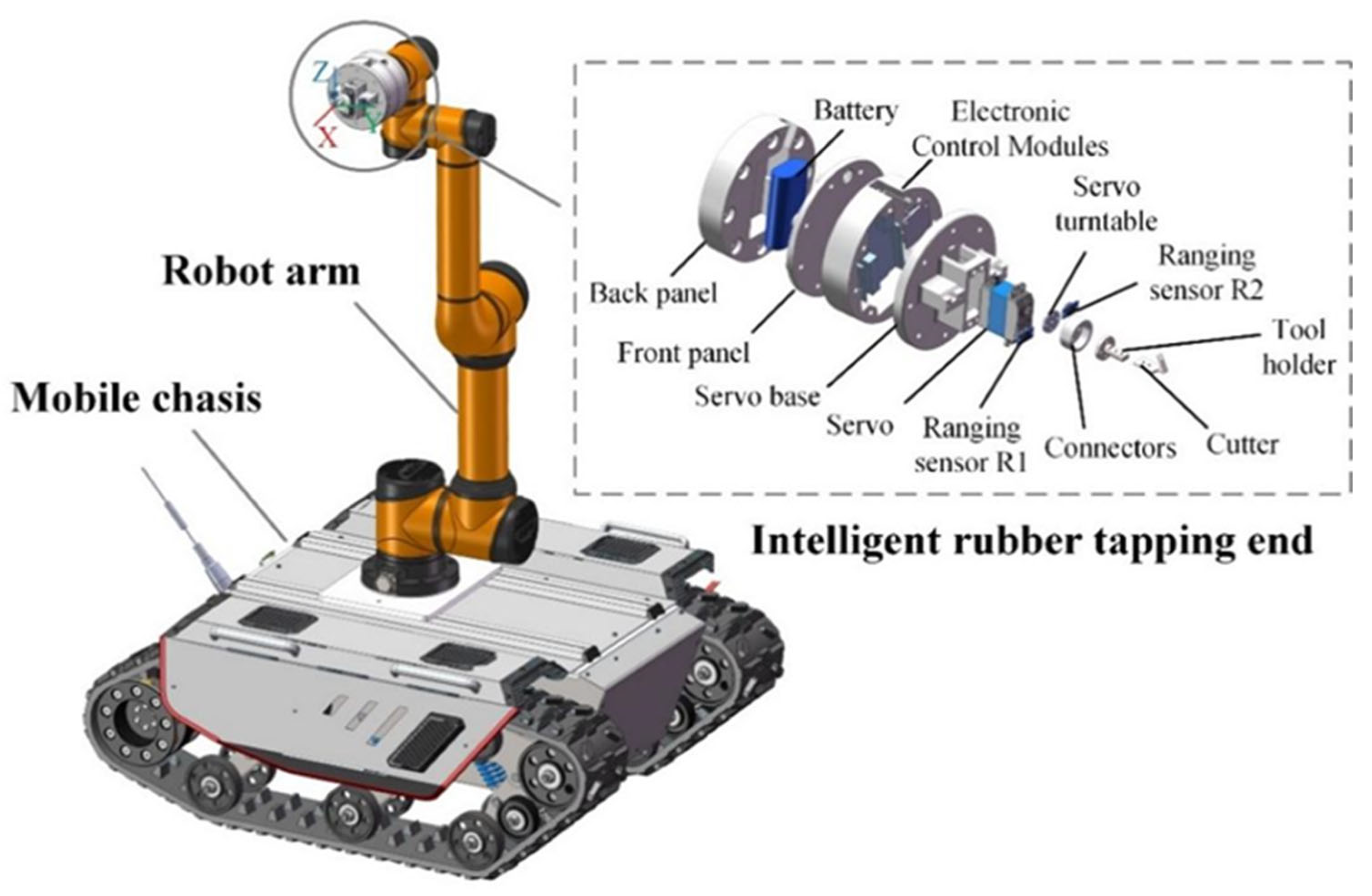
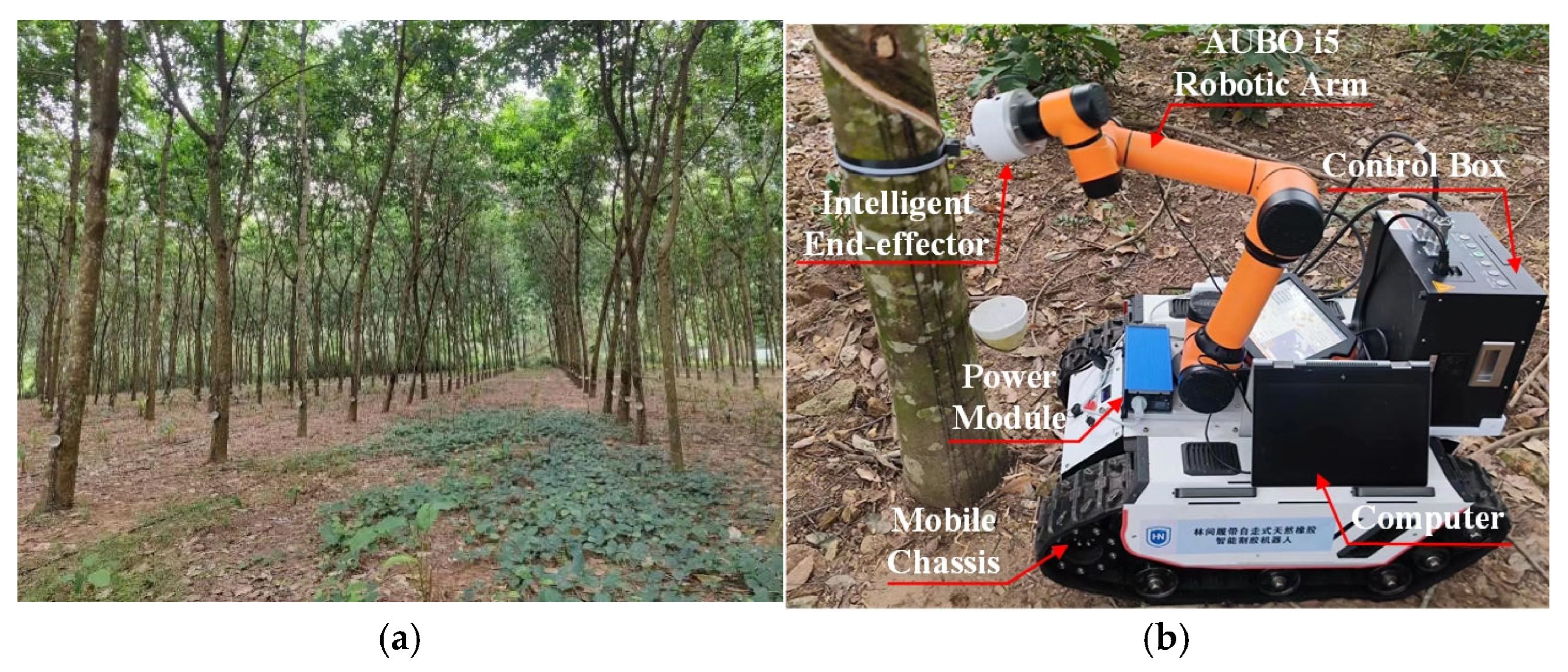
2.1. Structural Design of Rubber Tapping Robot

At the hardware level, highly integrated structural design can make rubber tapping more stable and reliable. It adopts a modular architecture of mobile chassis–robot arm–intelligent rubber tapping terminal. The intelligent rubber tapping terminal is composed of laser sensors, steering gears, electronic control modules, rubber tapping cutter, etc. The specific configuration is shown in Figure 2. When the robot is working, the mobile chassis first moves to the vicinity of the rubber tree, and the robotic arm aligns the intelligent rubber tapping terminal with the position where rubber needs to be tapped and produces the tapping track. The intelligent rubber tapping terminal detects real-time tapping depth data through laser sensors and dynamically adjusts the distance of the tapping knife.
The tapping depth of the robot is measured by a pair of laser sensors installed at the end. The tapping depth measurement method is shown in Figure 3. The laser sensor obtains the current tapping depth of the tapping cutter by detecting the distance between the tapped bark surface and the uncut bark surface. The tapping depth is shown in Equation (1).
a p = D 1 D 2
where D 1 is the tapped bark distance measured by sensor 1, D 2 is the uncut bark distance measured by sensor 2, and a p is the tapping depth, all in millimeters.

2.2. Modeling of the Robotic Arm of a Rubber Tapping Robot

The robotic arm of the rubber tapping robot selected in this research is the AUBO-i5 robotic arm produced by AUBO Technology Co., and the real product is shown in Figure 4a. The corresponding reference coordinate system X i Y i Z i is determined after specifying the Z i and X i axes for each of the links of the robot arm, as shown in Figure 4b. The Z i   (   i = 1 ,   2 ,   3 ,     6 ) axis represents the rotation axis of joint i, and its positive direction of rotation is determined by the right-hand rule. When i = 0, the coordinate system {0} represents the reference system of the base, which is stationary with respect to the mounting carrier, so it is used as the base coordinate system. After determining the reference coordinate system of each connecting rod, the transformation order of two adjacent connecting rod coordinate systems is specified by the improved D-H parameter method [31], and each joint D-H parameter contains four variables, which are the length of the link α i 1 , the torsion angle of the two rods α i 1 , the joint offset d i , and the joint angle θ i , and the improved D-H parameter of the robotic arm is shown in Table 1.

2.3. Transfer Function of Rubber Tapping Robot System

Obtaining an accurate mathematical model is the prerequisite for carrying out robot tapping depth control in a dynamic environment. During the robot tapping process, tapping depth control can be regarded as a time-varying constant distance control system [32]. The constant distance control system adjusts the feed rate of the tapping knife by combining the feedback of the laser sensor to achieve the purpose of constant tapping depth. The system flow includes three parts: actuator action, sensor measurement, and controller processing. To derive the transfer function, it is assumed that the system is linear within small deviations, the system has only one input and output, the sensor and actuator dynamics can be approximated by first-order inertial links, and external interference is not considered. Firstly, the dynamic first-order inertia link of the actuator is expressed as:
τ m d x ( t ) d t + x t = K m u ( t )
In Equation (2), x(t) is the actuator position, u(t) is the set depth, τm is the actuator position time constant, and Km is the actuator position gain.
Applying the Laplace transform to Equation (2), we obtain:
τ m X s + X s = K m U ( s )
Arranged:
X s = K m τ m s + 1 U ( s )
Secondly, the measurement dynamic first-order inertia link of the sensor is expressed as:
τ s d y ( t ) d t + y t = K s x ( t )
where y(t) is the position of the actuator measured by the sensor, τs is the time constant of the sensor, and KS is the sensor gain (assuming KS, that is, the sensor has no error).
Applying the Laplace transform to Equation (5), we obtain:
τ s s Y s + Y s = Y ( s )
Arranged:
Y s = 1 τ s s + 1 X ( s )
Then, the transfer function of the PID controller selected for this article is:
G c s = K p + K i s + K d s
where Kp is proportional gain, Ki is integral gain, Kd is differential gain.
Then the system open-loop transfer function is:
G o p e n s = G c s · G a c t u a t o r s · G s e n s o r s
In Equation (9), G a c t u a t o r s = K m τ m s + 1 , G s e n s o r s = 1 τ s s + 1 .
Multiply each part and sort it out to obtain:
G o p e n s = K m ( K p s 2 + K i s + K d ) ( τ m s + 1 ) ( τ s s + 1 ) s
The closed-loop transfer function of the system G c l o s e d s is defined as:
G c l o s e d s = Y ( s ) R ( S ) = G o p e n s 1 + G o p e n s
where R(S) is the Laplace transform of the given depth.
Substituting G o p e n s into Equation (11), we obtain:
G c l o s e d s = K m ( K p s 2 + K i s + K d ) τ m s + 1 τ s s + 1 s + K m ( K p s 2 + K i s + K d )
After simplification:
G c l o s e d s = K m ( K p s 2 + K i s + K d ) τ m τ s s 3 + τ m + τ s + K m K p s 2 + τ m + τ s + K m K i s + ( 1 + K m K d )
In Equation (13), the position time constant of the actuator and the time constant of the sensor are the times required for the system output to reach 63.2% of the steady-state value, which are measured to be 0.5 s and 0.02 s, respectively, through the step response test in reference [33]. The actuator position gain is the change in output position caused by a unit control input. The actuator position gain is calculated using Equation (14).
K m = K t · N
where Kt is the torque constant and N is the transmission ratio. In this research, the actuator used an MG996R servo, with a torque constant Kt of about 0.008 N·m/A and a transmission ratio N of 60, and Km = 0.48 is calculated.
Substituting into Equation (13), we obtain:
G c l o s e d s = 0.48 ( K p s 2 + K i s + K d ) 0.01 s 3 + 0.52 + 0.48 K p s 2 + 0.52 + 0.48 K i s + ( 1 + 0.48 K d )

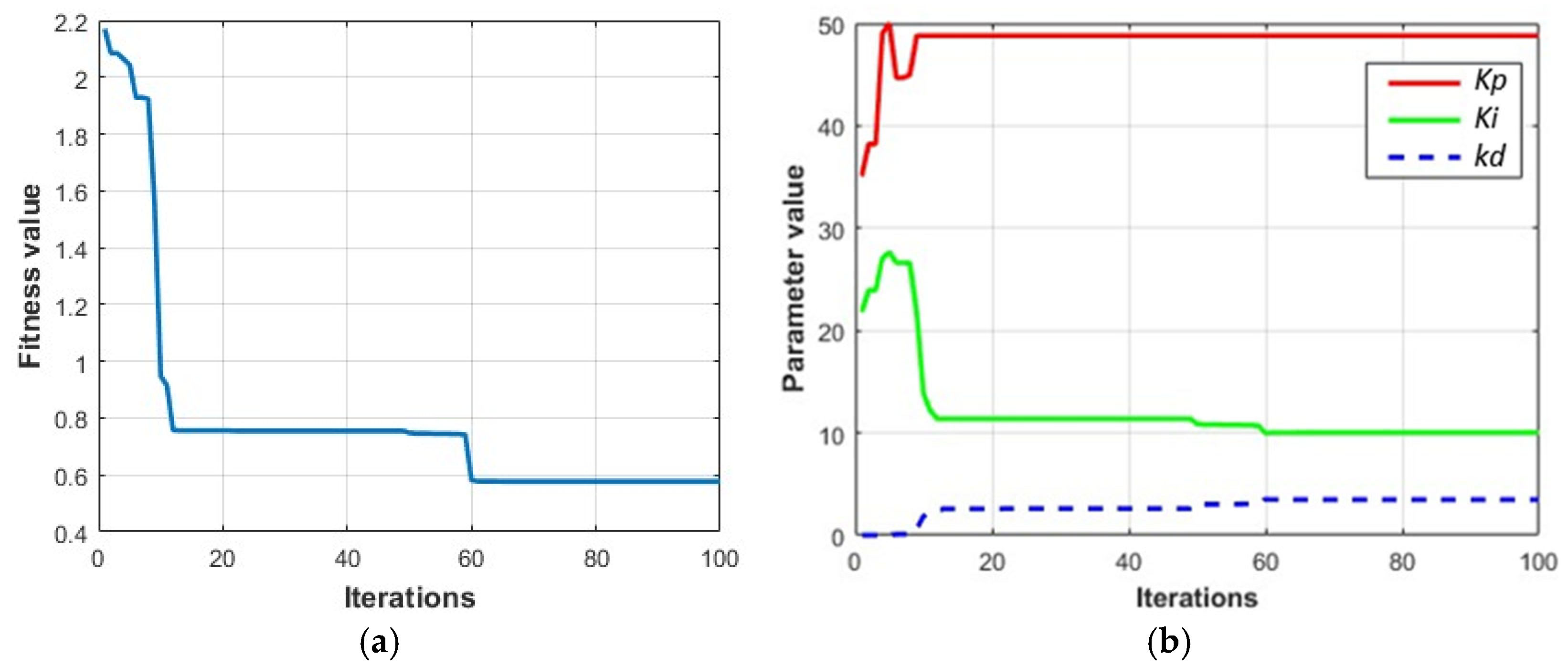
2.4. Analysis of PID Controller Based on PSO Algorithm

In this research, an improved PSO-PID controller is proposed to address the poor control of tapping depth due to external disturbances in conventional PID controllers. This design has adopted a PID controller with an adaptive control strategy. The PSO algorithm will initialize a three-dimensional particle swarm consisting of position, speed, and fitness, in which the three position vectors correspond to the control parameters and are searched and updated. When the particle swarm undergoes iterative evolution, its individual extreme value and global extreme value meet the requirements of the fitness function, or when the maximum number of iterations is reached, the search for the optimal solution is completed. The PID controller is shown in Equation (16). The principle of the PID control system based on the PSO algorithm is shown in Figure 5.
u ( t ) = K p e ( t ) + K i · e ( t ) d t + K d d e ( t ) d t
where e t = r t y t , r ( t ) is the system input, y ( t ) is the system output, e ( t ) is the controller, K p ,     K i ,     K d are proportional, integral and differential, respectively.
In terms of fitness function selection, time multiplied by the integral of the absolute value of error (ITAE) is selected as the performance evaluation index of the PID controller. and the equation is shown in Equation (17). The smaller the absolute value of the error, the better the performance of the PID controller.
I T A E M I N = 0 t | e ( t ) | d t

2.4.1. Improvement of Inertial Weight

The inertia weights ω have a significant role in balancing the convergence speed and global search capability of the algorithm. Sigmoid output as a probabilistic explanation can guide particles to approach excellent solutions with a certain probability, thereby increasing the diversity and flexibility of the search and preventing premature convergence [34]. In this research, the Sigmoid function is introduced to stimulate the particles to seek the optimal solution as fast as possible to improve the accuracy and convergence. The adaptive inertia weights based on the Sigmoid function are formulated as follows:
ω t = ω m a x ( ω m a x ω m i n ) × T t
T t = 1 1 + e x p ( k × ( t t m i d ) t m a x t m i d )
where t is the current number of iterations; ω t is the inertia weight at the t-th iteration; ω m a x and ω m i n are the maximum and minimum values of the inertia weights, respectively; t m a x is the total number of iterations; t m i d is the total number of iterations; k is a parameter that controls the steepness of the Sigmoid function, which determines the smoothness of the weight adjustment.

2.4.2. Improvement of Learning Factors

The convergence of logarithmic functions in many practical problems is characterized by being fast at first and then slow. Moreover, compared with linear or exponential functions, the gradient descent is smooth, which reduces the risk of falling into the local optimum too quickly [35]. To adapt to the dynamic adjustment strategy of the algorithm, dynamic changes are achieved as the number of iterations increases. In this research, the nonlinear asynchronous learning factor is constructed by introducing the logarithmic function, so that the algorithm has a strong local development ability in the early stage, and the later stage should have a strong global search ability, and the improved learning factor equation is as follows:
c 1 = c 1 _ m a x ( c 1 _ m a x c 1 _ m i n ) × l n ( 1 + ( e 1 ) × k / k m a x )
c 2 = c 2 _ m a x ( c 2 _ m a x c 2 _ m i n ) × l n ( 1 + ( e 1 ) × k / k m a x )
where k is the number of iterations, and c 1 _ m a x , c 2 _ m a x ,   c 1 _ m i n , c 2 _ m i n are the upper and lower bounds of the learning factors c 1 and c 2 .

2.4.3. Improved Particle Swarm Optimization Algorithm Process

V i k + 1 = ω t V i k + c 1 r 1 ( P b e s t k X i k ) + c 2 r 2 ( G b e s t k X i k )
X i k + 1 = X i k + V i k + 1  
The improved PSO-PID algorithm flow is shown in Algorithm 1. It is consistent with the basic particle swarm algorithm in the velocity update Equation (13) and position update Equation (14). Here, V i k is the d-dimensional component of the velocity vector of particle i in the kth iteration; X i k is the d-dimensional component of the position vector of particle i in the kth iteration; r1, r2 are two random functions with values in the range [0, 1]; P b e s t k is the best position ever experienced by particle i ; G b e s t k is the best position experienced by all particles within the group.
Algorithm 1 Improved PSO-PID Algorithm.
Input: Number of particles: N; Maximum number: tmax; Inertia weight range: ωmin, ωmax; Learning
factor range: c1_min, c1_max, c2_min, c2_max; PID parameter: K p , K i , K d
Output: Optimal PID parameters: kp_opt, ki_opt, kd_opt; Minimum fitness value: ITAEMIN
1:
for i = 1 to N do
2:
    Initialize Position X i k and Velocity V i k
3:
     X i k and V i k ← PID parameter: K p , K i , K d
4:
end for
5:
repeat
6:
    for each particle i
7:
        Calculate fitness value ITAEMIN
8:
        if ITAEMIN > pbest in history
9:
            pbest = ITAEMIN
10:
      end if
11:
    Choose the particle with the best fitness value of all the particles as the gbest
12:
    Calculate ω and c1, c2 according to Equations (18)–(21)
13:
    Calculate particle velocity according to Equation (22)
14:
    Update particle position according to Equation (23)
15:
    if ITAEMIN < gbest in history
16:
        gbest = ITAEMIN
17:
    end if
18:
end for
19:
Returnkp_opt, ki_opt, kd_opt, ITAEMIN

2.5. Parameter Configuration

In this experiment, a combination of simulation and field experiments will be used to verify the optimized rubber tapping performance of the rubber tapping robot. The computer configuration for the simulation experiment is CPU: Intel Xeon Silver 4210@2.20GHz, GPU: NVIDIA QuadroRTX4000, and the selected software is MatlabR2022a (Version 9.12). The algorithm parameters in the simulation environment of the rubber tapping robot are set as shown in Table 2. Real robotic arm rubber tapping required an accurate rubber tapping trajectory; based on the AUBO robotic arm D-H parameters, the robotic arm modeling and the use of fifth-degree polynomial interpolation trajectory planning to generate the spiral rubber tapping trajectory (Figure 6), the generated spiral trajectory is continuous and smooth, to satisfy the requirements of rubber tapping. The field experiments were conducted in August 2024 in a natural rubber forest at Hainan University (Figure 7a), and the field configuration of the rubber tapping robot is shown in Figure 7b. Here, 30 rubber trees with the same growth year were selected to test the relevant algorithms.

2.6. Experimental Process

The rubber tapping of the rubber tapping robot is divided into four parts: tool setting, starting rubber tapping, rubber tapping and finishing rubber tapping (Figure 8). According to the experimental program flow, the robot first completes the tool setting to determine the position of the starting tapping point, and starts the rubber tapping operation program through the generated rubber tree trajectory. Next, the improved PSO-PID algorithm generates relevant parameter output and feeds it back to the control system. The control system adjusts and taps rubber according to the optimal parameters until the rubber tapping is completed.

3. Results and Discussion

3.1. Simulation Experiment Results

After the PID control method of the tapping depth of the rubber tapping robot is optimized by improved PSO, whether the response time of the robot control system is improved, whether the robot tapping control system has overshoot and whether it meets the requirements, we configure the algorithm parameters of the rubber tapping robot control system according to Table 2 to conduct the related experiments.
Setting the target distance to 5.0 mm, the improved PSO optimal individual fitness value curve and K p , K i , K d optimization curves are obtained, as shown in Figure 9. It can be seen from Figure 9a that when the number of iterations is 60, the minimum fitness value ITAEMIN reaches the optimal solution, and the optimal solution is 0.577. Figure 9b is the graph of the change of the PID controller parameters with the number of iterations, and it can be seen from the graph that with the increase in the number of iterations, the controller parameters are gradually stabilized in a constant and bounded value, and gradually tend to be stabilized. The best individual K p value is 48.791; K i value is 10.022; K d value is 3.458.
To verify the comprehensive performance of the algorithms, with the parameters of the improved PSO-PID algorithm unchanged, the algorithms based on GA-PID [20], GWO-PID [21], and SOA-PID [22] have been selected for comparison with the target values set at 5.0 mm, 5.5 mm, 6.0 mm, and 6.5 mm. The optimization criteria were the settling time and overshoot, and the error range was ± 2%. A comparison of the four sets of control curves is obtained from the experiments again, as shown in Figure 10. Compared with the other algorithms, the improved PSO-PID algorithm has a short settling time and low adjustment amount at the four target values, which showed that the depth control of the rubber tapping robot can be significantly improved by using the improved PSO-PID. Combined with the average settling time and overshoot in Table 3, the minimum settling time of the improved PSO-PID is only 0.298 s, which can be faster than the fastest GWO-PID algorithm in other algorithms by 0.543 s, which can improve the response speed of the depth control of the rubber tapping robot. The improved PSO-PID can be controlled to an average overshoot of 2.5%, which has proved that this algorithm can effectively improve the robustness of the system.
In addition, according to the mechanical properties of rubber tree bark, when the rubber tapping depth is deeper, it will be easier to hurt the internal cortex, and the regulation algorithm will need to respond quickly and be adjusted. From the simulation results, the improved PSO-PID algorithm is more sensitive when the rubber tapping depth in deeper; when the target value is 6.5 mm, the overshoot amount is 3.05%, which fully meets the needs of designing the rubber tapping control system for robots. The improved PSO-PID algorithm is 2.47 times faster in average settling time and 11.77% lower in average overshoot compared to GA-PID; 2.27 times faster in average settling time and 12.88% lower in average overshoot compared to GWO-PID; 2.36 times faster in average settling time and 7.57% lower in average overshoot compared to SOA-PID. Relative to PID, the average settling time is 3.03 times faster and the average overshoot is decreased by 24.94%.
In conclusion, the average regulation time of PSO-PID is shorter, it reaches the steady state value faster, and the overshoot value is smaller and the stability is stronger, so the depth control system of the rubber tapping robot adopts the PSO-PID algorithm, which is favorable for the precise regulation of rubber tapping.

3.2. Forest Tapping Experiment Results

The performance of the rubber tapping robot with improved PSO-PID algorithm after the simulation effect was excellent, but the real more realistic rubber forest rubber tapping performance is the most important. Through the actual rubber tapping distance measurement experiments, we can clarify the optimal depth distance rubber tapping, and with the manual rubber tapping and electric rubber tapping cutter comparison experiments, we can further analyze the actual performance of rubber tapping robots in rubber forests, in order to verify the feasibility of the rubber tapping depth control algorithm for use in rubber forests.
Rubber tapping depth in a rubber forest was experimentally investigated with the rubber tapping robot that used laser sensors mounted on the end-effector. Data on the rubber tapping depth has been collected over a period of 60 s to analyze the change in depth at different distances from the rubber tree, as shown in Figure 11. As can be seen from the figure, the initial responsiveness increased as the laser sensor approached the rubber tree, resulting in a deeper tapping depth. Notably, the rubber tapping depth control exhibits smoother performance at a rubber tapping depth of 3.0 mm. To verify that the choice of 3.0 mm depth is universally applicable, 30 rubber trees of similar age and trunk diameter were tested. The experimental results are shown in Table 4, which indicate that the tapping depth of 3.0 mm observes the smallest error with an error range of 0.08 and a standard deviation of 0.01108, proving that the tapping robot has high accuracy in rubber tapping with the improved PSO-PID method.
In terms of rubber tapping injury rate, a comparison test was conducted by using a manual and electric rubber tapping cutter and rubber tapping with an optimized PSO-PID robot (Table 5). Under 3.0 mm rubber tapping depth, the rubber tapping robot with improved PSO-PID algorithm has an average rubber tapping depth accuracy better than that of skilled rubber tapping workers, and the rubber tapping injury rate is the same as that of manual rubber tapping, and lower than that of novice rubber tapping workers and the electric rubber tapping cutter.

4. Conclusions and Future Work

In this research, a precise rubber tapping robot control system was innovatively designed and the algorithm was verified, achieving accurate control with a depth error standard deviation as low as 0.01108 mm and a tree damage rate of 2% in actual rubber forests. Compared with the traditional PID algorithm, the average settling time was shortened by 3.03 times, and the overshoot was reduced by 24.94%, achieving the same operation quality as skilled manual tapping, and promoting a technological breakthrough in automated rubber tapping.
By introducing a dynamic inertia weight adjustment method that combines the Sigmoid function with a linear decreasing strategy, the global search and local development capabilities of the particle swarm algorithm (PSO) are balanced. Compared with the traditional fixed or linearly changing inertia weight, this method enhances the global search capability in the early stage and improves the local optimization accuracy in the later stage, significantly improving the convergence speed and stability of the algorithm.
A dynamic learning factor adjustment method based on a logarithmic function is proposed to realize the optimization mode of focusing on local development in the early stage of the algorithm and global search in the later stage. Through nonlinear asynchronous update, it considers the dynamic balance of exploration and development capabilities during the algorithm iteration process, and solves the problem of traditional PSO parameters being rigid and easily falling into local optimality.
Although the current tapping depth has achieved good results, in the future, we will also focus on the yield and quality of rubber latex to further improve the performance of the designed system.

Author Contributions

R.X. designed the research methodology, including the specific experiments, and oversaw the collection, processing, and analysis of data. They also authored the initial draft of the paper and participated in its revisions. Y.L. contributed to the design of the research and the selection of methodologies. J.L. assisted in the collection, processing, and analysis of data. X.Z. participated in discussions and revisions of the paper, and provided experimental equipment, technology, or financial support. Z.Z. coordinated the planning, design, and implementation of the entire research project. All authors have read and agreed to the published version of the manuscript.

Funding

This research was funded by the National Natural Science Foundation of China Regional Innovation and Development Joint Fund, grant number (U23A20176), the National Modern Agricultural Industry Technology System Project, grant number (CARS-33-JX2), the Hainan Provincial Science and Technology Talent Innovation Project, grant number (KJRC2023C04), the Hainan University Collaborative Innovation Centre Research Project, grant number (XTCX2022NYB05), the Sanya Science and Technology Innovation Special Project, grant number (2022KJCX94).

Institutional Review Board Statement

Not applicable.

Data Availability Statement

The data presented in this study are available on request from the corresponding author. The data are not publicly available due to the fact that the robot is in the research and development stage and involves some patent privacy.

Conflicts of Interest

The authors declare that there are no conflicts of interest.

References

  1. Fan, H.; Luo, X.; Sun, Z.H.; Yuan, X.; Qiu, S. Multi-model fusion based on Stacking: A predictive model for the price trend of natural rubber. In Proceedings of the 2020 IEEE 16th International Conference on Automation Science and Engineering (CASE), Hong Kong, China, 20–21 August 2020; pp. 1237–1242. [Google Scholar]
  2. Yang, H.; Sun, Z.J.; Liu, J.X.; Zhang, Z.F.; Zhang, X.R. The Development of Rubber Tapping Machines in Intelligent Agriculture: A Review. Appl. Sci.-Basel 2022, 12, 9304. [Google Scholar] [CrossRef]
  3. Chambon, B.; Duangta, K.; Promkhambut, A.; Lesturgez, G. Field latex production in Southern Thailand: A study on farmers’ and traders’ practices that may affect the quality of natural rubber latex delivered to the factories. J. Rubber Res. 2020, 23, 125–137. [Google Scholar] [CrossRef]
  4. Yatawara, Y.; Brito, W.; Perera, M.; Balasuriya, D. “Appuhamy”-the fully automatic rubber tapping machine. Engineer 2019, 27, 27–33. [Google Scholar] [CrossRef]
  5. Arjun, R.N.; Soumya, S.J.; Vishnu, R.S.; Bhavani, R.R. Semi automatic rubber tree tapping machine. In Proceedings of the 2016 International Conference on Robotics and Automation for Humanitarian Applications (RAHA), Coimbatore, India, 18–20 December 2016; pp. 1–5. [Google Scholar]
  6. Rodrigo, V.; Kudaligama, K.; Fernando, K.; Yapa, P. Harvesting the rubber tree once in four days; a solution to current issues in the rubber industry in Sri Lanka. J. Rubber Res. Inst. Sri Lanka 2011, 91, 15–35. [Google Scholar] [CrossRef]
  7. Mi, W. Development and Key Technology Research of Fully Automatic Rubber Tapping Machine. Master’s Thesis, Guangdong Ocean University, Guangdong, China, 2020. [Google Scholar]
  8. Zhou, H.; Zhang, S.L.; Zhang, J.X.; Zhang, C.L.; Wang, S.; Zhai, Y.H.; Li, W. Design, development, and field evaluation of a rubber tapping robot. J. Field Robot. 2022, 39, 28–54. [Google Scholar] [CrossRef]
  9. Zhou, H.; Gao, J.; Zhang, F.; Zhang, J.; Wang, S.; Zhang, C.; Li, W. Evaluation of Cutting Stability of a Natural-Rubber-Tapping Robot. Agriculture 2023, 13, 583. [Google Scholar] [CrossRef]
  10. Zheng, T.; Xu, A.; Xu, X.; Liu, M. Modeling and Compensation of Inertial Sensor Errors in Measurement Systems. Electronics 2023, 12, 2458. [Google Scholar] [CrossRef]
  11. Cui, W.; Lu, Z.; Li, C.; Han, X. A proactive approach to solve integrated production scheduling and maintenance planning problem in flow shops. Comput. Ind. Eng. 2018, 115, 342–353. [Google Scholar] [CrossRef]
  12. Nakaya, M.; Yoshizumi, H. Report on Basic Feedback Control Education and a Practical PID Tuning Method for Technical Staff and Operators. In Proceedings of the IEEE 15th International Conference on Control and Automation (ICCA), Edinburgh, Scotland, 16–19 July 2019; pp. 746–751. [Google Scholar]
  13. Wang, L.; Huang, C.; Li, T.; Cao, J.; Zheng, Y.; Huang, J. An Optimization Study on a Novel Mechanical Rubber Tree Tapping Mechanism and Technology. Forests 2023, 14, 2421. [Google Scholar] [CrossRef]
  14. Zhang, G.; Daraz, A.; Khan, I.A.; Basit, A.; Khan, M.I.; Ullah, M. Driver Training Based Optimized Fractional Order PI-PDF Controller for Frequency Stabilization of Diverse Hybrid Power System. Fractal Fract. 2023, 7, 315. [Google Scholar] [CrossRef]
  15. Dai, M.J.; Zhang, Z.L.; Lai, X.; Lin, X.H.; Wang, H. PID controller-based adaptive gradient optimizer for deep neural networks. IET Control Theory Appl. 2023, 17, 2032–2037. [Google Scholar] [CrossRef]
  16. Ahmadi, A.; Esfanjani, R.M. Automatic tuning of PID controllers using deep recurrent neural networks with pruning based on tracking error. J. Instrum. 2024, 19, P02028. [Google Scholar] [CrossRef]
  17. Ratre, A.; Pankajakshan, V. Deep Imbalanced Data Learning Approach for Video Anomaly Detection. In Proceedings of the 28th National Conference on Communications (NCC), Online, 24–27 May 2022; pp. 391–396. [Google Scholar]
  18. Li, W.; Wang, G.G.; Gandomi, A.H. A Survey of Learning-Based Intelligent Optimization Algorithms. Arch. Comput. Methods Eng. 2021, 28, 3781–3799. [Google Scholar] [CrossRef]
  19. Sahin, A.K.; Cavdar, B.; Ayas, M.S. An adaptive fractional controller design for automatic voltage regulator system: Sigmoid-based fractional-order PID controller. Neural Comput. Appl. 2024, 36, 14409–14431. [Google Scholar] [CrossRef]
  20. Xiao, Y.; Yu, A.; Qi, H.; Jiang, Y.; Zhou, W.; Gao, N.; Liu, W. Research on the tension control method of lithium battery electrode mill based on GA optimized Fuzzy PID. J. Intell. Fuzzy Syst. 2021, 40, 10211–10234. [Google Scholar] [CrossRef]
  21. Chen, K.; Xiao, B.; Wang, C.Y.; Liu, X.L.; Liang, S.N.; Zhang, X. Cuckoo Coupled Improved Grey Wolf Algorithm for PID Parameter Tuning. Appl. Sci.-Basel 2023, 13, 12944. [Google Scholar] [CrossRef]
  22. Chen, C.; Li, J.; Luo, J.; Xie, S.; Li, H. Seeker optimization algorithm for optimal control of manipulator. Ind. Robot: An. Int. J. 2016, 43, 677–686. [Google Scholar] [CrossRef]
  23. Shami, T.M.; El-Saleh, A.A.; Alswaitti, M.; Al-Tashi, Q.; Summakieh, M.A.; Mirjalili, S. Particle swarm optimization: A comprehensive survey. IEEE Access 2022, 10, 10031–10061. [Google Scholar] [CrossRef]
  24. Eberhart, R.C.; Shi, Y. Comparing inertia weights and constriction factors in particle swarm optimization. In Proceedings of the 2000 Congress on Evolutionary Computation (CEC), La Jolla, CA, USA, 16–19 July 2000; pp. 84–88. [Google Scholar]
  25. Chen, H.T.; Wang, W.C.; Chen, X.N.; Qiu, L. Multi-objective reservoir operation using particle swarm optimization with adaptive random inertia weights. Water Sci. Eng. 2020, 13, 136–144. [Google Scholar] [CrossRef]
  26. Ni, Q.; Deng, J. A New Logistic Dynamic Particle Swarm Optimization Algorithm Based on Random Topology. Sci. World J. 2013, 2013, 409167. [Google Scholar] [CrossRef]
  27. Zhang, W.; Li, G.; Zhang, W.; Liang, J.; Yen, G.G. A cluster based PSO with leader updating mechanism and ring-topology for multimodal multi-objective optimization. Swarm Evol. Comput. 2019, 50, 100569. [Google Scholar] [CrossRef]
  28. Quan, W.; Wang, J.; He, Z.; Zuo, J. Selective Ensemble Based on Probability PSO Algorithm; Springer International Publishing: Heidelberg, NY, USA, 2018; pp. 273–280. [Google Scholar]
  29. Sharma, M.; Chhabra, J.K. Sustainable automatic data clustering using hybrid PSO algorithm with mutation. Sustain. Comput. Inform. Syst. 2019, 23, 144–157. [Google Scholar] [CrossRef]
  30. Yadav, R.K.; Anubhav. PSO-GA based hybrid with Adam Optimization for ANN training with application in Medical Diagnosis. Cogn. Syst. Res. 2020, 64, 191–199. [Google Scholar] [CrossRef]
  31. Gao, G.; Sun, G.; Na, J.; Guo, Y.; Wu, X. Structural parameter identification for 6 DOF industrial robots. Mech. Syst. Signal Process. 2018, 113, 145–155. [Google Scholar] [CrossRef]
  32. Mu, D.; Wang, G.; Fan, Y. A Time-Varying Lookahead Distance of ILOS Path Following for Unmanned Surface Vehicle. J. Electr. Eng. Technol. 2020, 15, 2267–2278. [Google Scholar] [CrossRef]
  33. Rake, H. Step Response and Frequency Response Methods. IFAC Proc. Vol. 1979, 12, 519–526. [Google Scholar] [CrossRef]
  34. Liu, W.; Wang, Z.; Yuan, Y.; Zeng, N.; Hone, K.; Liu, X. A novel sigmoid-function-based adaptive weighted particle swarm optimizer. IEEE Trans. Cybern. 2019, 51, 1085–1093. [Google Scholar] [CrossRef]
  35. Huang, H.; Qin, H.; Hao, Z.; Lim, A. Example-based learning particle swarm optimization for continuous optimization. Inf. Sci. 2012, 182, 125–138. [Google Scholar] [CrossRef]
Figure 1. The effects of different tapping depths on rubber trees: (a) excessively shallow tapping and (b) excessively deep tapping.
Agriculture 15 01089 g001
Figure 2. Model diagram of rubber tapping robot.
Agriculture 15 01089 g002
Figure 3. Diagram of tapping depth.
Agriculture 15 01089 g003
Figure 4. Robotic arm of rubber tapping robot: (a) AUBO-i5; (b) coordinate system of robotic arm.
Agriculture 15 01089 g004
Figure 5. Schematic diagram of PID controller based on PSO algorithm.
Agriculture 15 01089 g005
Figure 6. Robotic arm trajectory.
Agriculture 15 01089 g006
Figure 7. Rubber tapping robot experiment field: (a) Hainan University Rubber Forest; (b) rubber tapping robot field configuration.
Agriculture 15 01089 g007
Figure 8. Rubber tapping robot flow chart.
Agriculture 15 01089 g008
Figure 9. PSO-PID algorithm performance curve: (a) optimal individual fitness value; (b) PID optimization curve.
Agriculture 15 01089 g009
Figure 10. Experiments with different parameters: (a) setpoint = 5.0 mm; (b) setpoint = 5.5 mm; (c) setpoint = 6.0 mm; (d) setpoint = 6.5 mm [20,21,22].
Agriculture 15 01089 g010
Figure 11. The depth of rubber tapping at different distances.
Agriculture 15 01089 g011
Table 1. Kinematics parameters of the robot manipulator.
Joint i ai-1 (mm)αi-1 (°)di (mm) θ i  (°)
100122180
20−90121.5−90
340818000
43761800−90
50−90102.50
6090940
Table 2. Simulation parameters.
ParametersValue
number of particles: N100
maximum number of iterations: tmax100
Inertia weight: ωmin, ωma0.4,1.6
Learning factor: c1_min, c1_max, c2_min, c2_max0.8, 1.5, 0.8, 1.5
K p ,   K i ,   K d 40, 15, 1
Table 3. Performance comparison of four different setpoints and different algorithms.
SetpointAlgorithmSettling Time (s)Overshoot (%)
5.0 mmPSO-PID0.6072.71
GA-PID0.91423.89
GWO-PID0.92210.24
SOA-PID0.8994.15
PID1.47327.82
5.5 mmPSO-PID0.2981.23
GA-PID0.9229.07
GWO-PID0.98310.14
SOA-PID1.00518.92
PID1.21123.76
6.0 mmPSO-PID0.3071.31
GA-PID1.10213.02
GWO-PID1.08810.94
SOA-PID1.0748.22
PID1.09725.93
6.5 mmPSO-PID0.4653.05
GA-PID1.1999.38
GWO-PID0.84119.7
SOA-PID0.9867.29
PID1.30530.56
Table 4. Performance comparison of four different tap depths.
Tap Depth (mm)Max Depth (mm)Min Depth (mm)Average Depth (mm)Standard Deviation
22.191.882.010.02087
2.52.632.392.510.01889
33.082.933.010.01108
3.53.713.413.520.02008
Table 5. Comparison of different rubber tapping methods.
Rubber Tapping MethodAverage Rubber Tapping Depth (mm)Rubber Tapping Injury Tree Rate (%)
Manual rubber tapping (novice)3.718
Manual rubber tapping (skilled)3.112
Electric Rubber Tapping Cutter3.496
PSO-PID Optimized Rubber Tapping3.022
Disclaimer/Publisher’s Note: The statements, opinions and data contained in all publications are solely those of the individual author(s) and contributor(s) and not of MDPI and/or the editor(s). MDPI and/or the editor(s) disclaim responsibility for any injury to people or property resulting from any ideas, methods, instructions or products referred to in the content.

