Abstract
In absorption systems using the aqueous lithium bromide mixture, the Coefficient of Performance is affected by the desorber. The main function of this component is to separate the refrigerant fluid from the working mixture. In conventional boiling desorbers, constant heat flux and vacuum pressure conditions are necessary to carry out the desorption process, and usually, the absorbers are heavy and bulky; thus, they are not suitable in compact systems. In this study, a membrane desorber was evaluated, operating at atmospheric pressure conditions with a water/lithium bromide solution with a concentration of 49.6% w/w. The effects of the solution temperature, solution mass flow, and condensation temperature on the desorption rate were analyzed. The maximum desorption rate value was 6.1 kg/m2h with the following operation conditions: the solution temperature at 95.2 °C, the solution mass flow at 4.00 × 10⁻² kg/s, and the cooling water temperature at 30.1 °C. On the other hand, the minimum value was 1.1 kg/m2h with the solution temperature at 80.2 °C, the solution mass flow at 2.50 × 10⁻² kg/s, and the cooling water temperature at 45.1 °C. The thermal energy efficiency, defined as the ratio between the thermal energy used to evaporate the refrigerant fluid with respect to the total thermal energy entering the membrane desorber, varied from 0.08 to 0.30. According to the results, a high solution mass flow, a high solution temperature, and a low condensation temperature lead to an increase in the desorption rate; however, a low solution mass flow enhanced the thermal energy efficiency. The proposed membrane desorber could replace a conventional boiling desorber, especially in absorption cooling systems that operate at high condensation temperatures as in warm weather regions.
1. Introduction
As fossil fuel sources are consumed and environmental awareness increases, technologies using renewable or sustainable energy sources are receiving significant interest. In the refrigeration sector, the interest in cooling systems driven by thermal energy is growing [1]. Absorption cooling systems are devices that can operate with renewable thermal energies (such as solar or geothermal) or low-grade waste heat from industrial processes; therefore, they are an eco-friendly option to conventional cooling compression systems. According to Solano-Olivares et al. [2], for the construction of an absorption cooling system, large amounts of energy and materials are required; as a result, the most negative environmental impacts of this technology are focused on this stage. Besides, a currently pending issue is the high ecotoxicity potential which is mostly created by the use of heavy metals for the manufacturing of stainless steel due to the corrosion caused by the saline solutions used as working mixtures. However, the authors concluded that an absorption cooling system powered by solar energy reduces the fossil fuel consumption and greenhouse gases (GHG) emissions by around 80% in both indicators; besides, their waste materials may be almost totally recycled [2]. Despite these ecological advantages, absorption cooling systems are large in size and weight, limiting small-scale applications. Besides, when a heat source is supplied at a low-temperature level, the refrigerant fluid separation from the working mixture (desorption process) is reduced, causing a decrease in the system cooling capacity [3]. Therefore, the desorber (also known as a generator) is the most restrictive component for absorption systems driven by renewable energy sources [4]. Several desorber designs have been proposed to overcome the large volume problem and to improve the heat and mass transfer processes, which include dual components (desorber and condenser) [5,6,7], enhanced falling-film configurations [8,9,10], and microchannel configurations [11,12,13]. In addition to the design geometries, the performance of any desorber is affected by the condenser. The increase in the condenser temperature increases the desorber pressure, which decreases the boiling rate and the Coefficient of Performance (COP) of the whole absorption system [14]. Condensers require auxiliary devices to deliver the latent heat of vaporization to the environment due to the refrigerant fluid condensation. Usually, cooling towers are used; however, they can increase the initial investment and maintenance costs, especially for small-scale applications [15]. In order to reduce the initial cost and avoid water consumption, an air-cooled absorption cooling system could be used [16].
Nonetheless, in the air-cooled mode of operation, the condenser pressure increases as the air temperature increases, causing an increment in the desorption temperature. Besides, in an absorption cooling device using the H2O/LiBr mixture, the LiBr crystallization risk increases as the desorption temperature increases [17]. These disadvantages limit the absorption systems for air conditioning in hot weather regions or automotive applications [18]. In this regard, membrane devices have become an alternative to conventional desorbers. Membrane Distillation (MD) is a separation process driven by thermal energy, mostly applied to separate volatile dissolved substances from a solvent/solute mixture [19]. The main advantages of MD, with respect to the conventional boiling desorption, include: operating temperatures lower than the boiling point temperatures of working mixtures, operating pressures close to the atmospheric condition, compact components, and by using polymeric materials, corrosion problems can be avoided [20]. In recent years, membrane-based devices have been analyzed and proposed to replace the conventional boiling desorbers, particularly for absorption cooling systems using the H2O/LiBr mixture. Table 1 shows the experimental reports about these components. Other aqueous mixtures have been tested [21,22], as well as different membrane-based desorber operation modes [23]. Comprehensive literature reviews about membrane technology in absorption heat pumps were carried out by Asfand and Bourouis [24] and Ibarra-Bahena et al. [25].

Table 1.
Experimental operating conditions of the membrane-based desorbers reported in the literature.
From the data shown in Table 1, the condensation temperature range used in membrane-based desorbers has been below 30 °C; in this paper, an experimental evaluation of a hydrophobic membrane-based desorber with condensation temperatures up to 45 °C at atmospheric pressure conditions is presented. The Air Gap Membrane Distillation (AGMD) configuration was used in the membrane device. The effects of different parameters such as H2O/LiBr solution temperature, cooling water temperature, and solution mass flow on the desorption rate have been analyzed as well on the thermal energy efficiency. The aim of this paper is to demonstrate the technical feasibility of the membrane desorber operated at condensation temperatures up to 45 °C for absorption cooling systems.
2. Air Gap Membrane Distillation Process
Membrane distillation is a thermal separation process in which only water vapor (or other volatile molecules) crosses through a hydrophobic porous membrane. An amount of water is evaporated on the liquid-membrane interphase at the hot side, passing through the porous membrane, and condensed on the cold side. The temperature difference between both membrane sides generates a partial pressure difference; this is the mass transfer driving force. The membrane’s function is to hold the vapor/liquid interphase created on both sides and, due to its hydrophobic nature, only water vapor crosses through it [34]. There are at least four configurations to generate the partial pressure difference across the membrane: Direct Contact Membrane Distillation (DCMD), where the hot saline solution and the permeate (that works as cooling fluid) are in direct contact with each side of the membrane surface; Sweeping Gas Membrane Distillation (SGMD), where an inert gas is used to transport the vapor to the cold side to condense outside the membrane module; Vacuum Membrane Distillation (VMD), where vacuum is generated in the cold side with a vacuum pump; and Air Gap Membrane Distillation (AGMD), where a stagnant air layer separates the membrane and the condensation surface; in the SGMD and VMD configurations, the permeate vapor condensation occurs in an external condenser [35]. An AGMD module comprises three sections: the feed section, the air-gap or permeate section, and the cooling section (see Figure 1).
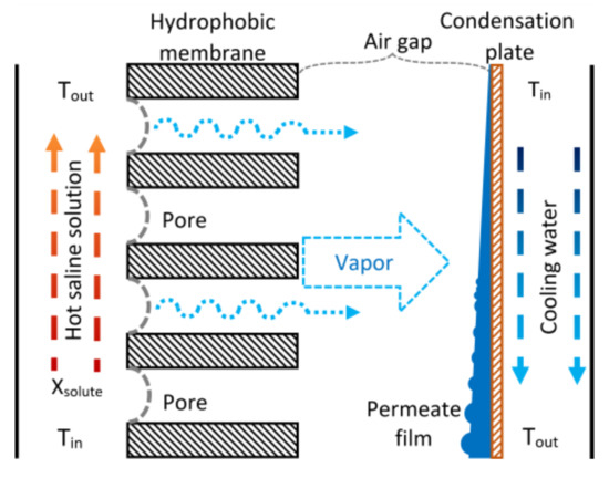
Figure 1.
Schematic diagram of the AGMD process.
The vapor coming from the feed section diffuses into the air gap, and it condenses on the cooling plate; the condensed permeate is drained out of the module. The coolant fluid flows on the other side of the cooling plate, removing the heat load produced by the vapor condensation. The AGMD configuration reduces the heat loss, and the temperature polarization is lower due to the stagnant air gap (because air has low thermal conductivity), but simultaneously, an additional mass transfer resistance is created. This mass transfer resistance reduces the permeate flux, and it is directly proportional to the airgap width [36]. A remarkable advantage of AGMD modules for absorption cooling applications is that they can operate at atmospheric pressure conditions.
3. Methodology
Different solution temperatures, solution mass flow rates, and cooling water temperatures were varied to analyze their effect on the desorption process. The H2O/LiBr solution was selected since it is the most used solution mixture in absorption cooling systems (using water as working fluid), and in general, the desorption process takes place at temperatures lower than 100 °C [37,38]. With the experimental data, a thermal energy efficiency analysis was carried out to quantify the membrane desorber’s performance.
3.1. Experimental Setup
The membrane-based desorber was integrated by two support plates made of Nylamid with 300 mm length, 200 mm wide, and 25.4 mm thickness; neoprene gaskets and thermal-resistant silicon gaskets with 1 and 3 mm thickness, respectively; a metallic mesh to upholding the membrane; an aluminum cooling plate with 0.4 mm thickness; and 24 bolts and nuts. The features of the membrane used are shown in Table 2. The desorber membrane area used in the desorber was 144 cm2. The experimental tests were carried out in Temixco, Morelos, Mexico, where the atmospheric pressure is approximately 87 kPa.

Table 2.
Membrane features.
The H2O/LiBr solution channel was 180 mm in length, 80 mm wide, and 3 mm thickness, and it was created by the junction of the support plate, the thermal-resistant silicon gasket, and the hydrophobic membrane. An air gap with 3 mm of thickness was at the other side of the hydrophobic membrane, two neoprene gaskets, the metallic mesh, one silicon gasket, and one side of the condensing plate. Finally, the cooling water flowed in the channel created by the other side of the condensing plate, the thermal-resistant silicon gasket, and the support plate. Figure 2 shows the components of the experimental membrane-based desorber.
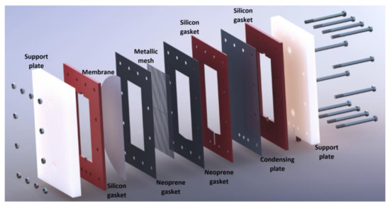
Figure 2.
Exploded view of the experimental membrane-based desorber.
A 316 SS plate heat exchanger (PHE) was used to heat transfer from the heating fluid to the H2O/LiBr solution, and the thermal source was a Cole-Parmer Polystat digital heating circulating bath of 6 L volume and 1000 W electrical power. The cooling water temperature was kept constant with a Julabo CORIO 601F refrigerated/heating circulator bath of 10 L volume and 2000 W. A Coriolis mass flowmeter was used to measure the solution mass flow rate (ṁLiBr). The heating fluid stream (Vhf) and the cooling water stream (Vcw) were measured with analogical flowmeters. A rubber septum was placed in the LiBr solution loop, and a liquid sample of the H2O/LiBr solution was drawn out for each experimental test. An ABBEMAT 200 refractometer was used to determine the salt solution concentration using a refractive index (RI) correlation previously reported for H2O/LiBr mixture [39]. The solution and the heating fluid were pumped by using two gear pumps of 32 W power. An electronic weighing scale was used to measure the amount of distilled water (wdis). The temperatures of the inlet and outlet streams of the membrane-based desorber and the PHE were measured with RTD pt100 temperature sensors. The experimental temperatures and the solution mass flow data were recorded by an Agilent data acquisition unit. Figure 3 describes the experimental setup, while Figure 4 shows a photograph of the experimental setup.
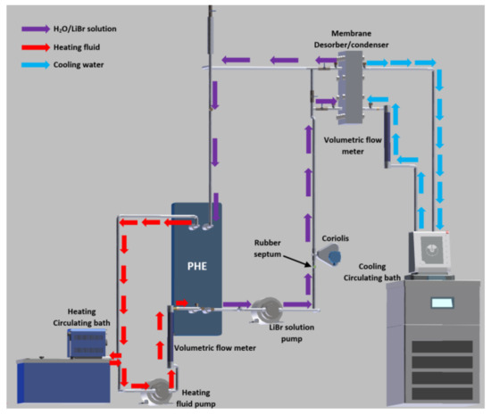
Figure 3.
Schematic diagram of the experimental setup.
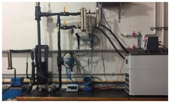
Figure 4.
Photograph of the experimental setup.
The uncertainties of the measured variables are shown in Table 3, while the operating conditions are present in Table 4.

Table 3.
Uncertainty of the measured variables.

Table 4.
Experimental operating conditions.
3.2. Thermal Energy Efficiency Analysis
As was described in previous sections, the AGMD process is driven by thermal energy to heat the aqueous solution. The thermal energy efficiency (ηT) is defined as the ratio between the heat used to evaporate part of the refrigerant fluid from the solution and the heat supplied to the AGMD device [40]:
In the AGMD module analyzed, Equation (1) was written as:
where λvap is the water vaporization heat, Amem is the membrane area, ṁLiBr is the H2O/LiBr solution mass flow, CpLiBr is the H2O/LiBr solution specific heat, and TLiBr,in and TLiBr,out are the H2O/LiBr solution inlet and outlet temperatures, respectively.
The desorption rate (Jw) is defined as the mass flow of water vapor desorbed (ṁvap) crossing the membrane area.
The thermodynamic properties of the H2O/LiBr solution were calculated using the correlations reported by Kaita [41].
4. Results
4.1. Desorption Rate
The experimental desorption rate (Jw) was measured based on the mass of distillate water (wdis) produced by the membrane-desorber after a defined time period. The Jw as a function of the H2O/LiBr solution mass flow rate (ṁLiBr) at different inlet H2O/LiBr solution temperature (TLiBr,in) and different inlet cooling water temperatures (Tcw,in) are shown in Figure 5, Figure 6, Figure 7 and Figure 8. TLiBr,in and Tcw,in refer to the temperature of the H2O/LiBr solution and the cooling water, respectively, at the membrane-desorber entrance. Figure 5 shows the desorption rate as a function of the solution mass flow rate with solution temperatures of 80 °C, 85 °C, 90 °C, and 95 °C, and constant cooling water temperature of 45.1 °C. It can be observed that the effect of the solution temperature is higher than the solution mass flow effect on the desorption rate. The increment of ṁLiBr from 2.50 × 10⁻² kg/s to 4.00 × 10⁻² kg/s causes a moderate increment (15% on average) on Jw with constant TLiBr,in. However, Jw considerably raises (240% on average) at the highest TLiBr,in value of 95.2 °C, with respect to the lowest temperature of 80.2 °C, with constant ṁLiBr. This behavior was expected, since, as it was commented in Section 2, the AGMD is a thermal separation process, and the driving force is the partial pressure difference, which is related to the temperature difference between both sides of the membrane; therefore, the increment in the solution temperature increases the partial pressure of the water vapor (refrigerant fluid) [42]. The solution mass flow rate enhances the desorption rate because, as the solution velocity increases, the heat and mass transfer resistances are reduced at the solution-membrane interphase [26,43]; however, the thermophysical properties of the H2O/LiBr which affect the heat and mass transfer resistances are influenced by the solution temperature.
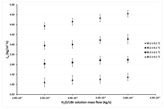
Figure 5.
Desorption rate as a function of the ṁLiBr with Tcw,in = 45.1 ± 0.1 °C.
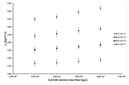
Figure 6.
Desorption rate as a function of the ṁLiBr with Tcw,in = 40.1 ± 0.1 °C.
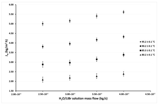
Figure 7.
Desorption rate as a function of the ṁLiBr with Tcw,in = 35.1 ± 0.1 °C.
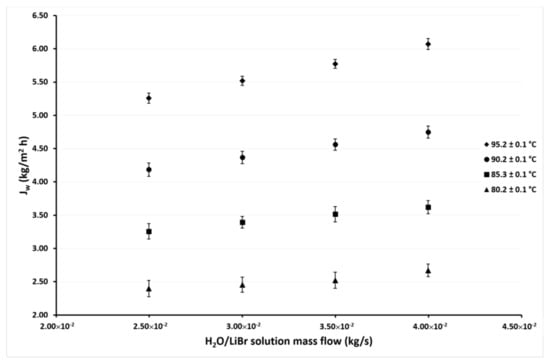
Figure 8.
Desorption rate as a function of the ṁLiBr with Tcw,in = 30.1 ± 0.1 °C.
Figure 6 shows the variation of Jw as a function of ṁLiBr with the same solution temperatures as in Figure 5 but with the cooling water temperature of 40.1 °C. As can be seen, the desorption rate behavior is similar as shown in Figure 5, but in this case, the Jw values are higher, since in this case, the minimum value was 1.7 kg/m2h, and the maximum value was 5.2 kg/m2h. These values represent an increment of 52% and 14% of the minimum and maximum values, respectively, over those reported in Figure 5 at the cooling water temperature of 45.1 °C. The effect of the ṁLiBr was similar to that observed in Figure 5, since the increment of Jw was 14% on average at the highest ṁLiBr value (4.00 × 10⁻² kg/s) with respect to the lowest value of 2.50 × 10⁻² kg/s at constant a TLiBr,in. Meanwhile, the Jw increased 169% on average at TLiBr,in = 95.2 °C with respect to the TLiBr,in = 80.2 °C.
Figure 7 and Figure 8 show the variation of Jw as a function of ṁLiBr at cooling water temperatures of 35.1 °C and 30.1 °C, respectively. In these figures, it can be seen that the same behaviors were shown in the previous figures. The effect of the ṁLiBr was the same magnitude as observed in Figure 5 and Figure 6 since the desorption rate increased by 14% and 13% on average at Tcw = 35.1 °C and Tcw = 30.1 °C, respectively. When TLiBr,in raised from 80.2 °C to 95.2 °C, the Jw increased 137% and 125% on average, respectively.
In Figure 5, Figure 6, Figure 7 and Figure 8, it can also be observed that the Jw values continuously increase as the condenser temperature decreases due to the mass transfer driving force increased by the reduction of the vapor partial pressure in the membrane desorber cooling plate (cold side). This effect was remarkable at TLiBr,in = 80.2 °C since the Jw increased 164% on average at Tcw,in = 30.1 °C, with respect to Tcw,in = 45.1 °C. The solution temperature effect was the most influential parameter on the desorption rate, the cooling water temperature was the second, and finally, the solution mass flow. These results are in concordance with the literature, since for the membrane desorber operation, the highest technically viable solution temperature is recommended [44].
4.2. Thermal Energy Efficiency
The calculated energy efficiencies (ηT) for the highest (Tcw,in = 45.1 °C) and lowest (Tcw,in = 30.1 °C) cooling water temperatures for the tested H2O/LiBr solution mass flows and the different solution temperatures are shown in Figure 9 and Figure 10. Similar behavior of the ηT was calculated with the other cooling water temperatures, but they are not presented, in an attempt to avoid repeatability.
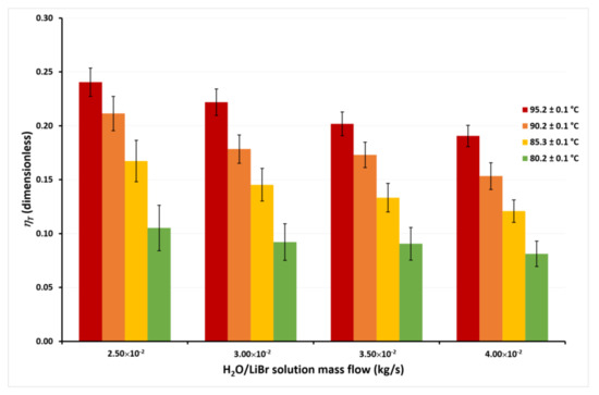
Figure 9.
Thermal energy efficiency as a function of the ṁLiBr with Tcw,in = 45.1 ± 0.1 °C.
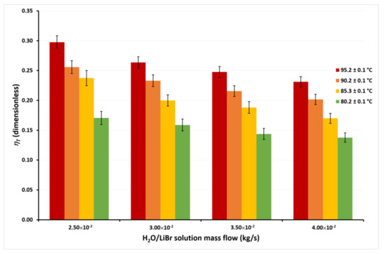
Figure 10.
Thermal energy efficiency as a function of the ṁLiBr with Tcw,in = 30.1 ± 0.1 °C.
In Figure 9, it can be seen that the ηT achieves the highest values at the lowest ṁLiBr value, independently of the solution temperatures. This occurs since, as previously discussed, although ṁLiBr increased 60%, from 2.50 × 10⁻² kg/s to 4.00 × 10⁻², Jw increased by only 14% on average at any TLiBr,in value. Therefore, an increase in the solution mass flow causes a net decrease in the ηT from Equation (2). On the other hand, it can be observed that ηT increased 132% on average for the different mass flows when TLiBr,in increases from 80.2 °C to 95.2 °C. This is because, as observed in Figure 5, Figure 6, Figure 7 and Figure 8, the effect of the solution temperature on the Jw was higher than the effect of the mass flow. The effect of the cooling water temperature on the thermal energy efficiency can be appreciated by comparing the ηT values from Figure 9 and Figure 10. At a solution temperature of 80.2 °C, a mass flow of 4.00 × 10⁻² kg/s, and a condenser temperature of 45.1 °C, the ηT is 0.08, while at the same values of the solution temperature and the solution mass flow but a condenser temperature of 30.1 °C, the ηT is 0.14. Taking into account all the ηT values at the different mass flows, the efficiency raised 66% on average at a TLiBr,in = 80.2 °C, when the condenser temperature decreases from 45.1 °C to 30.1 °C. However, at the highest solution temperature (TLiBr,in = 95.2 °C) the ηT increased only 22% (average) at Tcw,in = 30.1 °C, with respect to Tcw,in = 45.1 °C.
According to Figure 4, Figure 5, Figure 6 and Figure 7, the desorption rate is slightly affected by the cooling water temperature compared to the solution temperature. As the cooling water temperature increases, the desorption rate decreases by the reduction in the vapor pressure gradient. The vapor partial pressure in the hot side increases exponentially with the increase in the solution temperature compared to the small increment of the vapor partial pressure by the cooling water reduction [45]; thus, the effect of the cooling water temperature on the thermal efficiency was higher at TLiBr,in = 80.2 °C than TLiBr,in = 95.2 °C. For this reason, some authors suggest using the highest available solution temperature rather than decreasing the cooling water temperature to improve the performance of a membrane distillation device [36,44]. The highest ηT value was 0.30 at TLiBr,in = 95.2 °C, Tcw,in = 30.1 °C, and ṁLiBr = 2.50 × 10⁻² kg/s, while the lowest ηT value was 0.08 at TLiBr,in = 80.2 °C, Tcw,in = 45.1 °C, and ṁLiBr = 4.00 × 10⁻² kg/s.
The calculated thermal energy efficiency for the desorption process was significantly lower than the conventional desalination process, which is from 0.95 to 0.99 [42,46,47]. However, when concentrated salt solutions (like brines) are used, the ηT decreases; e.g., with a 24% w/w of NaCl concentration, the ηT was 0.30 [48].
5. Conclusions
A membrane-based desorber using the AGMD configuration operating with the H2O/LiBr mixture at atmospheric pressure conditions was evaluated. Condenser temperatures from 30 to 45 °C were selected to simulate environment temperatures in warm weather regions. The solution temperature, the cooling water temperature, and the solution mass flow on the desorption rate were studied. Since membrane distillation is a thermal separation process, the desorption rate was improved as the LiBr solution temperature increased and the cooling water temperature decreased. Additionally, according to the experimental data, as the LiBr solution mass flow increased, the desorption rate increased also. It can be explained by the decrease in the heat and concentration boundary layers as the solution velocity flow increased; thus, the desorption rate was enhanced. However, the influence of the solution mass flow on the desorption rate was minimal (14% on average) with respect to the cooling water and solution effects. The maximum desorption rate value was 6.1 kg/m2 h at a solution mass flow of 4.00 × 10⁻² kg/s, solution temperature of 95.2 °C, and a cooling water temperature of 30.1 °C. On the other hand, the minimum value was 1.1 kg/m2h, and it was obtained at the lowest mass flow and solution temperature and the highest cooling water temperature. Unlike the desorption rate, the thermal energy efficiency was improved as the solution mass flow decreased. The highest value was 0.30 at the highest solution temperature and the lowest cooling water temperature and solution mass flow. The membrane desorber proposed in this study has feasible potential in absorption cooling applications, especially with systems operating at high condense temperatures (up to 45 °C) as those required in warm weather regions. In addition, the desorption process was carried out at atmospheric pressure conditions; therefore, a vacuum pump was unnecessary for the operation of this component, which is an advantage with respect to the conventional boiling desorbers.
Author Contributions
Conceptualization, J.I.-B., W.R., S.D.N.-M., R.J.R., E.V.-R., and U.D.-C.; methodology, J.I.-B., W.R., S.D.N.-M., R.J.R., E.V.-R., and U.D.-C.; writing—original draft preparation, J.I.-B., W.R., and U.D.-C.; writing—review and editing, J.I.-B., W.R., S.D.N.-M., R.J.R., E.V.-R., and U.D.-C.; supervision, J.I.-B., W.R., R.J.R., E.V.-R., and U.D.-C.; project administration W.R., E.V.-R., and U.D.-C.; funding acquisition, W.R., E.V.-R., and U.D.-C. All authors have read and agreed to the published version of the manuscript.
Funding
This research received no external funding.
Institutional Review Board Statement
Not applicable.
Informed Consent Statement
Not applicable.
Data Availability Statement
Not applicable.
Acknowledgments
Authors thank the FORDECYT 297486, PAPIIT-UNAM IT100920, IMTA-RD2103.1, and IMTA- RD2102.2 projects for the financial support. Ulises Dehesa-Carrasco wishes to thank IMTA for the “1772 Cátedras CONACYT México”. The authors appreciate the technical support provided by Olga García Villa.
Conflicts of Interest
The authors declare no conflict of interest.
References
- Kim, D.S.; Infante Ferreira, C.A. Air-cooled LiBr–water absorption chillers for solar air conditioning in extremely hot weathers. Energy Convers. Manag. 2009, 168, 252–269. [Google Scholar] [CrossRef]
- Solano–Olivares, K.; Romero, R.; Santoyo, E.; Herrera, I.; Galindo–Luna, Y.; Rodríguez–Martínez, A.; Santoyo-Castelazo, E.; Cerezo, J. Life cycle assessment of a solar absorption air-conditioning system. J. Clean. Prod. 2019, 240, 118206. [Google Scholar] [CrossRef]
- Han, X.-D.; Zhang, S.-W.; Tang, Y.; Yuan, W.; Li, B. Mass transfer enhancement for LiBr solution using ultrasonic wave. J. Central South Univ. 2016, 23, 405–412. [Google Scholar] [CrossRef]
- Xu, Z.; Wang, R. Solar-powered absorption cooling systems. In Advances in Solar Heating and Cooling; Elsevier BV: Amsterdam, The Netherlands, 2016; pp. 251–298. [Google Scholar]
- Delgado-Gonzaga, J.; Juárez-Romero, D.; Saravanan, R.; Márquez-Nolasco, A.; Huicochea, A.; Morales, L. Performance analysis of a dual component generator-condenser of an absorption heat transformer for water desalination. Therm. Sci. Eng. Prog. 2020, 20, 100651. [Google Scholar] [CrossRef]
- Hu, T.; Xie, X.; Jiang, Y. A detachable plate falling film generator and condenser coupling using lithium bromide and water as working fluids. Int. J. Refrig. 2019, 98, 120–128. [Google Scholar] [CrossRef]
- Yi, Y.; Hu, T.; Xie, X.; Jiang, Y. Experimental assessment of a detachable plate falling film heat and mass exchanger couple using lithium bromide and water as working fluids. Int. J. Refrig. 2020, 113, 219–227. [Google Scholar] [CrossRef]
- Hu, T.; Xie, X.; Jiang, Y. Design and experimental study of a plate-type falling-film generator for a LiBr/H2O absorption heat pump. Int. J. Refrig. 2017, 74, 304–312. [Google Scholar] [CrossRef]
- Lee, J.H.; Kim, D.H.; Kim, S.M.; Kim, M.S.; Kim, I.G.; Woo, S.M.; Hong, S.J.; Park, C.W. Heat transfer characteristics of a falling film generator for various configurations of heating tubes in an absorption chiller. Appl. Therm. Eng. 2019, 148, 1407–1415. [Google Scholar] [CrossRef]
- Shi, C.; Chen, Q.; Jen, T.-C.; Yang, W. Heat transfer performance of lithium bromide solution in falling film generator. Int. J. Heat Mass Transf. 2010, 53, 3372–3376. [Google Scholar] [CrossRef]
- Keinath, C.M.; Nagavarapu, A.K.; Delahanty, J.C.; Garimella, S.; Garrabrant, M.A. Experimental assessment of alternative compact configurations for ammonia-water desorption. Appl. Therm. Eng. 2019, 161, 113852. [Google Scholar] [CrossRef]
- Delahanty, J.C.; Garimella, S.; Garrabrant, M.A. Design of compact microscale geometries for ammonia–water desorption. Sci. Technol. Built Environ. 2015, 21, 365–374. [Google Scholar] [CrossRef]
- Determan, M.D.; Garimella, S. Ammonia–water desorption heat and mass transfer in microchannel devices. Int. J. Refrig. 2011, 34, 1197–1208. [Google Scholar] [CrossRef]
- Arun, M.; Maiya, M.; Murthy, S. Equilibrium low pressure generator temperatures for double-effect series flow absorption refrigeration systems. Appl. Therm. Eng. 2000, 20, 227–242. [Google Scholar] [CrossRef]
- Al-Alili, A.; Islam, M.; Kubo, I.; Hwang, Y.; Radermacher, R. Modeling of a solar powered absorption cycle for Abu Dhabi. Appl. Energy 2012, 93, 160–167. [Google Scholar] [CrossRef]
- Xu, Z.; Wang, R. Comparison of absorption refrigeration cycles for efficient air-cooled solar cooling. Sol. Energy 2018, 172, 14–23. [Google Scholar] [CrossRef]
- Izquierdo, M.; Venegas, M.; Rodríguez, P.; Lecuona, A. Crystallization as a limit to develop solar air-cooled LiBr–H2O absorption systems using low-grade heat. Sol. Energy Mater. Sol. Cells 2004, 81, 205–216. [Google Scholar] [CrossRef]
- Inada, T.; Tomita, H.; Takemura, F.; Tsubouchi, O.; Hihara, E. Crystallization temperature, vapor pressure, density and viscosity of lithium bromide+lithium iodide+ethylene glycol+water system for absorption refrigerators for automotive use. Int. J. Refrig. 2019, 100, 274–283. [Google Scholar] [CrossRef]
- Lawson, K.W.; Lloyd, D.R. Membrane distillation. J. Membr. Sci. 1997, 124, 1–25. [Google Scholar] [CrossRef]
- Izquierdo-Gil, M.; García-Payo, M.; Fernández-Pineda, C. Air gap membrane distillation of sucrose aqueous solutions. J. Membr. Sci. 1999, 155, 291–307. [Google Scholar] [CrossRef]
- Bahena, J.I.; Carrasco, U.D.; González, M.M.; Romero, R.; Pensado, M.A.B.; Cristóbal, O.H. Experimental evaluation of a membrane contactor unit used as a desorber/condenser with water/Carrol mixture for absorption heat transformer cycles. Exp. Therm. Fluid Sci. 2016, 76, 193–204. [Google Scholar] [CrossRef]
- Riffat, S.; Wu, S.; Bol, B. Pervaporation membrane process for vapour absorption system. Int. J. Refrig. 2004, 27, 604–611. [Google Scholar] [CrossRef]
- Ibarra-Bahena, J.; Rivera, W.; Romero, R.; Montiel-González, M.; Dehesa-Carrasco, U. Novel intermittent absorption cooling system based on membrane separation process. Appl. Therm. Eng. 2018, 136, 718–729. [Google Scholar] [CrossRef]
- Asfand, F.; Bourouis, M. A review of membrane contactors applied in absorption refrigeration systems. Renew. Sustain. Energy Rev. 2015, 45, 173–191. [Google Scholar] [CrossRef]
- Ibarra-Bahena, J.; Raman, S.; Galindo-Luna, Y.R.; Rodríguez-Martínez, A.; Rivera, W. Role of Membrane Technology in Absorption Heat Pumps: A Comprehensive Review. Membranes 2020, 10, 216. [Google Scholar] [CrossRef]
- Venegas, M.; García-Hernando, N.; De Vega, M. Experimental evaluation of a membrane-based microchannel desorber operating at low desorption temperatures. Appl. Therm. Eng. 2020, 167, 114781. [Google Scholar] [CrossRef]
- Ibarra-Bahena, J.; Venegas-Reyes, E.; Galindo-Luna, Y.R.; Rivera, W.; Romero, R.J.; Rodríguez-Martínez, A.; Dehesa-Carrasco, U. Feasibility Analysis of a Membrane Desorber Powered by Thermal Solar Energy for Absorption Cooling Systems. Appl. Sci. 2020, 10, 1110. [Google Scholar] [CrossRef] [Green Version]
- Hong, S.J.; Hihara, E.; Dang, C. Analysis of adiabatic heat and mass transfer of microporous hydrophobic hollow fiber membrane-based generator in vapor absorption refrigeration system. J. Membr. Sci. 2018, 564, 415–427. [Google Scholar] [CrossRef]
- Ibarra-Bahena, J.; Dehesa-Carrasco, U.; Romero, R.; Rivas-Herrera, B.; Rivera, W. Experimental assessment of a hydrophobic membrane-based desorber/condenser with H2O/LiBr mixture for absorption systems. Exp. Therm. Fluid Sci. 2017, 88, 145–159. [Google Scholar] [CrossRef]
- Isfahani, R.N.; Fazeli, A.; Bigham, S.; Moghaddam, S. Physics of lithium bromide (LiBr) solution dewatering through vapor venting membranes. Int. J. Multiph. Flow 2014, 58, 27–38. [Google Scholar] [CrossRef]
- Bigham, S.; Isfahani, R.N.; Moghaddam, S. Direct molecular diffusion and micro-mixing for rapid dewatering of LiBr solution. Appl. Therm. Eng. 2014, 64, 371–375. [Google Scholar] [CrossRef]
- Wang, Z.; Gu, Z.; Feng, S.; Li, Y. Application of vacuum membrane distillation to lithium bromide absorption refrigeration system. Int. J. Refrig. 2009, 32, 1587–1596. [Google Scholar] [CrossRef]
- Sudoh, M.; Takuwa, K.; Iizuka, H.; Nagamatsuy, K. Effects of thermal and concentration boundary layers on vapour permeation in membrane distillation of aqueous lithium bromide solution. J. Membr. Sci. 1997, 131, 1–7. [Google Scholar] [CrossRef]
- Guillen-Burrieza, E.; Blanco, J.; Zaragoza, G.; Alarcón, D.-C.; Palenzuela, P.; Ibarra, M.; Gernjak, W. Experimental analysis of an air gap membrane distillation solar desalination pilot system. J. Membr. Sci. 2011, 379, 386–396. [Google Scholar] [CrossRef]
- Alkhudhiri, A.; Darwish, N.; Hilal, N. Produced water treatment: Application of Air Gap Membrane Distillation. Desalination 2013, 309, 46–51. [Google Scholar] [CrossRef]
- Kalla, S.; Upadhyaya, S.; Singh, K. Principles and advancements of air gap membrane distillation. Rev. Chem. Eng. 2019, 35, 817–859. [Google Scholar] [CrossRef]
- Srikhirin, P.; Aphornratana, S.; Chungpaibulpatana, S. A review of absorption refrigeration technologies. Renew. Sustain. Energy Rev. 2001, 5, 343–372. [Google Scholar] [CrossRef]
- Herold, K.E.; Radermacher, R.; Klein, S.A. Absorption Chillers and Heat Pumps; Informa UK Limited: London, UK, 2016. [Google Scholar]
- Romero, R.; Basurto-Pensado, M.; Jiménez-Heredia, A.; Sanchez-Mondragon, J. Working fluid concentration measurement in solar air conditioning systems. Sol. Energy 2006, 80, 177–181. [Google Scholar] [CrossRef]
- Khayet, M.; Matsuura, T. Economics, Energy Analysis and Costs Evaluation in MD. In Membrane Distillation; Elsevier BV: Amsterdam, The Netherlands, 2011; pp. 429–452. [Google Scholar]
- Kaita, T. Thermodynamic properties of lithium bromide–water solutions at high temperatures. Int. J. Refrig. 2001, 24, 374–390. [Google Scholar] [CrossRef]
- Xu, J.; Singh, Y.B.; Amy, G.L.; Ghaffour, N. Effect of operating parameters and membrane characteristics on air gap membrane distillation performance for the treatment of highly saline water. J. Membr. Sci. 2016, 512, 73–82. [Google Scholar] [CrossRef] [Green Version]
- Alklaibi, A.; Lior, N. Transport analysis of air-gap membrane distillation. J. Membr. Sci. 2005, 255, 239–253. [Google Scholar] [CrossRef]
- Venegas, M.; García-Hernando, N.; De Vega, M. A parametric analysis on the effect of design and operating variables in a membrane-based desorber. Int. J. Refrig. 2019, 99, 47–58. [Google Scholar] [CrossRef]
- Banat, F.A.; Simandl, J. Desalination by Membrane Distillation: A Parametric Study. Sep. Sci. Technol. 1998, 33, 201–226. [Google Scholar] [CrossRef]
- Liu, G.L.; Zhu, C.; Cheung, C.S.; Leung, C.W. Theoretical and experimental studies on air gap membrane distillation. Heat Mass Transf. 1998, 34, 329–335. [Google Scholar] [CrossRef]
- Khalifa, A.; Lawal, D.U.; Antar, M.; Khayet, M. Experimental and theoretical investigation on water desalination using air gap membrane distillation. Desalination 2015, 376, 94–108. [Google Scholar] [CrossRef]
- Schwantes, R.; Bauer, L.; Chavan, K.; Dücker, D.; Felsmann, C.; Pfafferott, J. Air gap membrane distillation for hypersaline brine concentration: Operational analysis of a full-scale module–New strategies for wetting mitigation. Desalination 2018, 444, 13–25. [Google Scholar] [CrossRef]
Publisher’s Note: MDPI stays neutral with regard to jurisdictional claims in published maps and institutional affiliations. |
© 2021 by the authors. Licensee MDPI, Basel, Switzerland. This article is an open access article distributed under the terms and conditions of the Creative Commons Attribution (CC BY) license (https://creativecommons.org/licenses/by/4.0/).