
Distillate Flux Enhancement of Direct Contact Membrane Distillation Modules with Inserting Cross-Diagonal Carbon-Fiber Spacers


Abstract
:1. Introduction
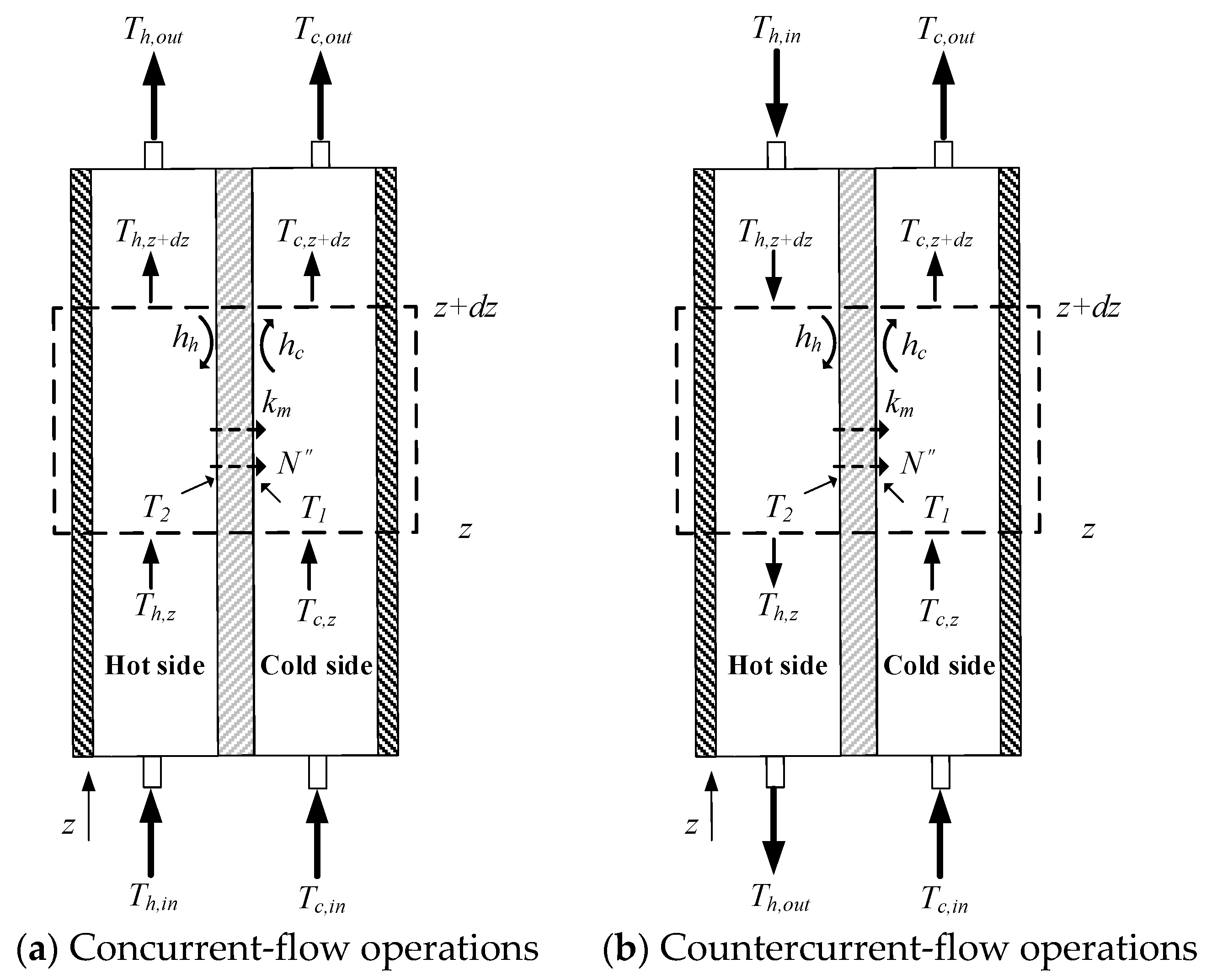
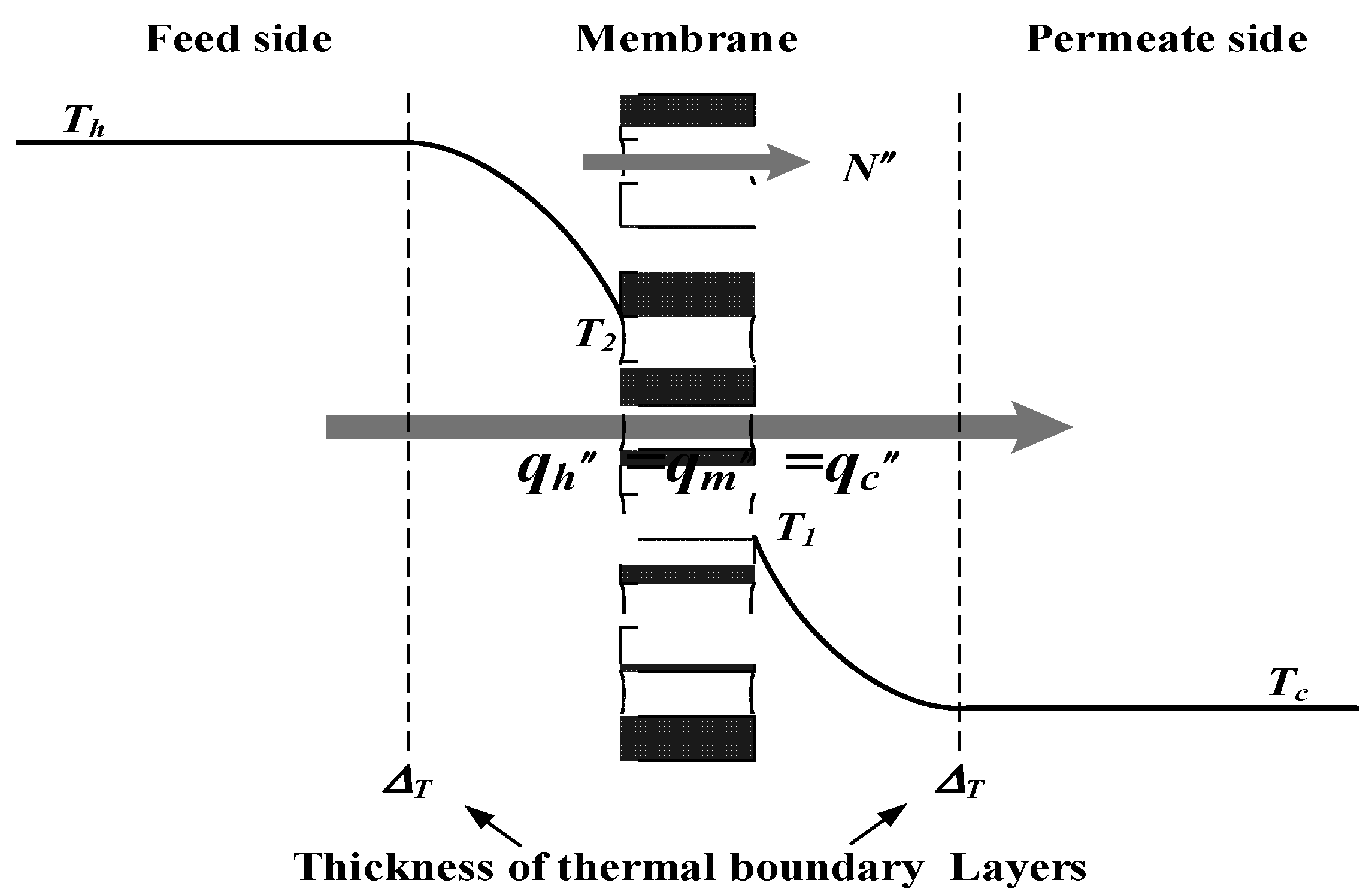
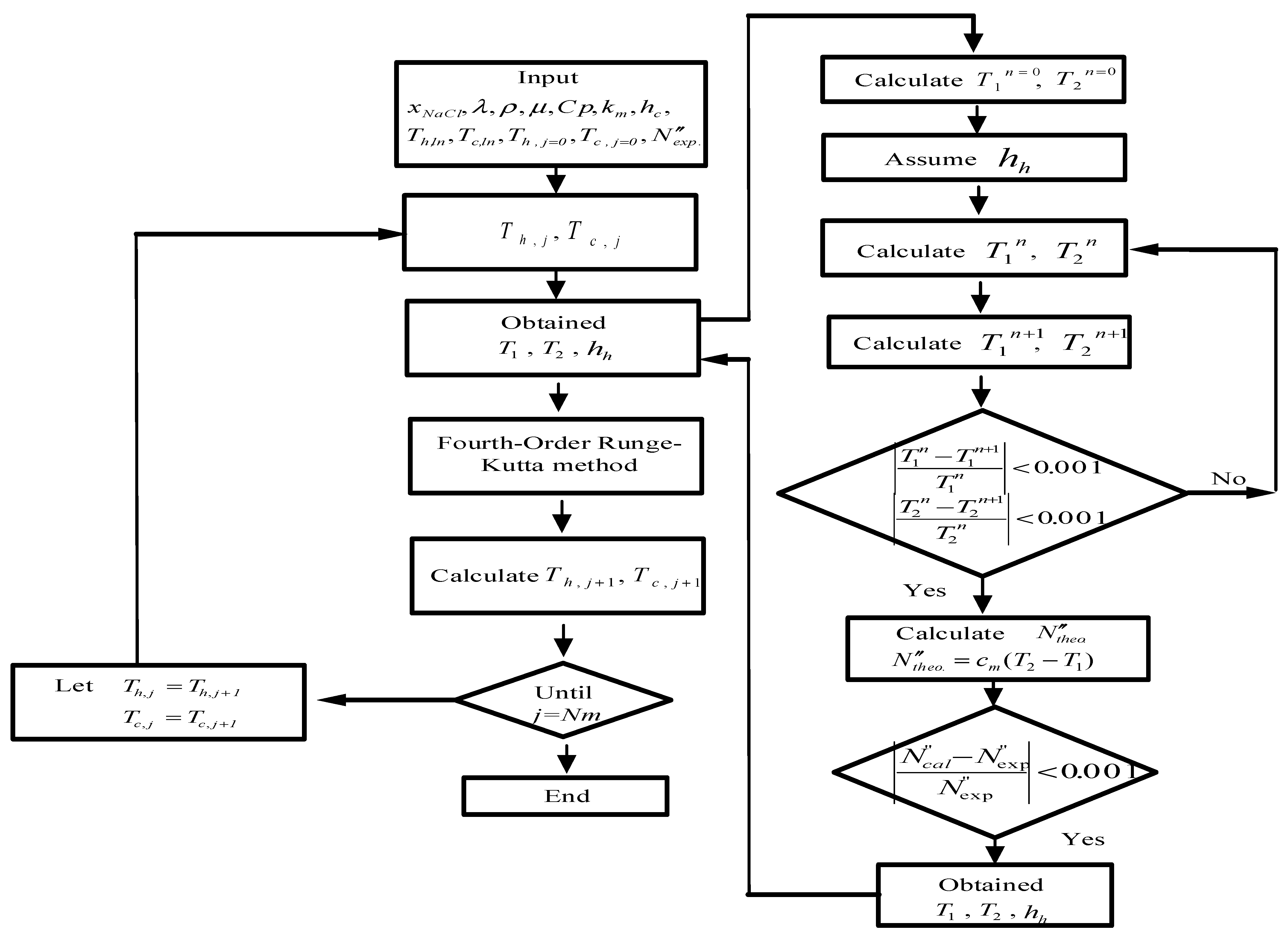
2. Theoretical Modeling of DCMD Modules
- (a)
- Steady-state operations;
- (b)
- Physical properties of fluid, frame plates, and membrane are constants;
- (c)
- Stagnant air within the membrane pore;
- (d)
- Mass transfer by diffusion and heat transfer by conduction associated with latent heat through the hydrophobic membrane;
- (e)
- No water transporting through the hydrophobic membrane;
- (f)
- Good insulation on the entire circumference of modules.
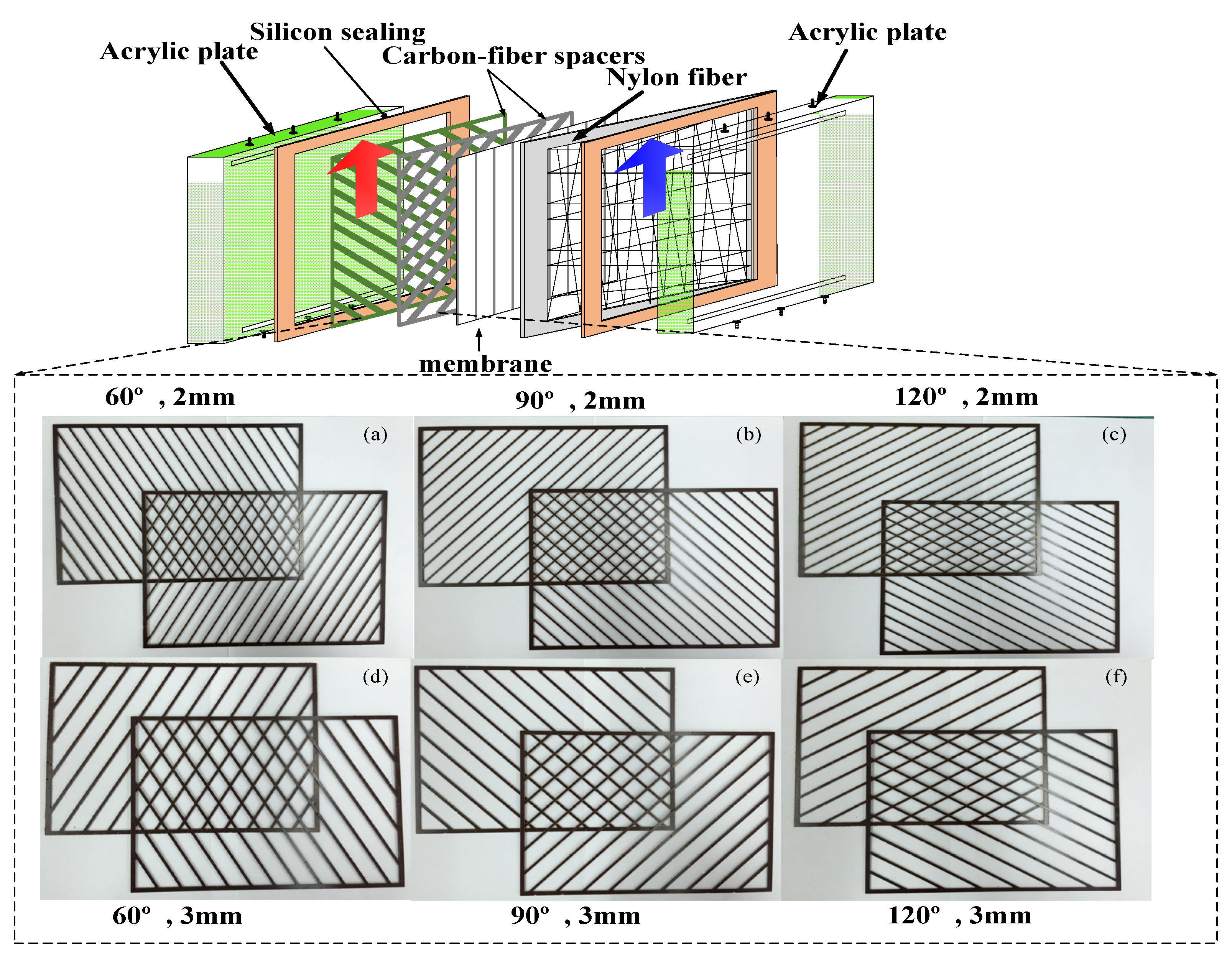
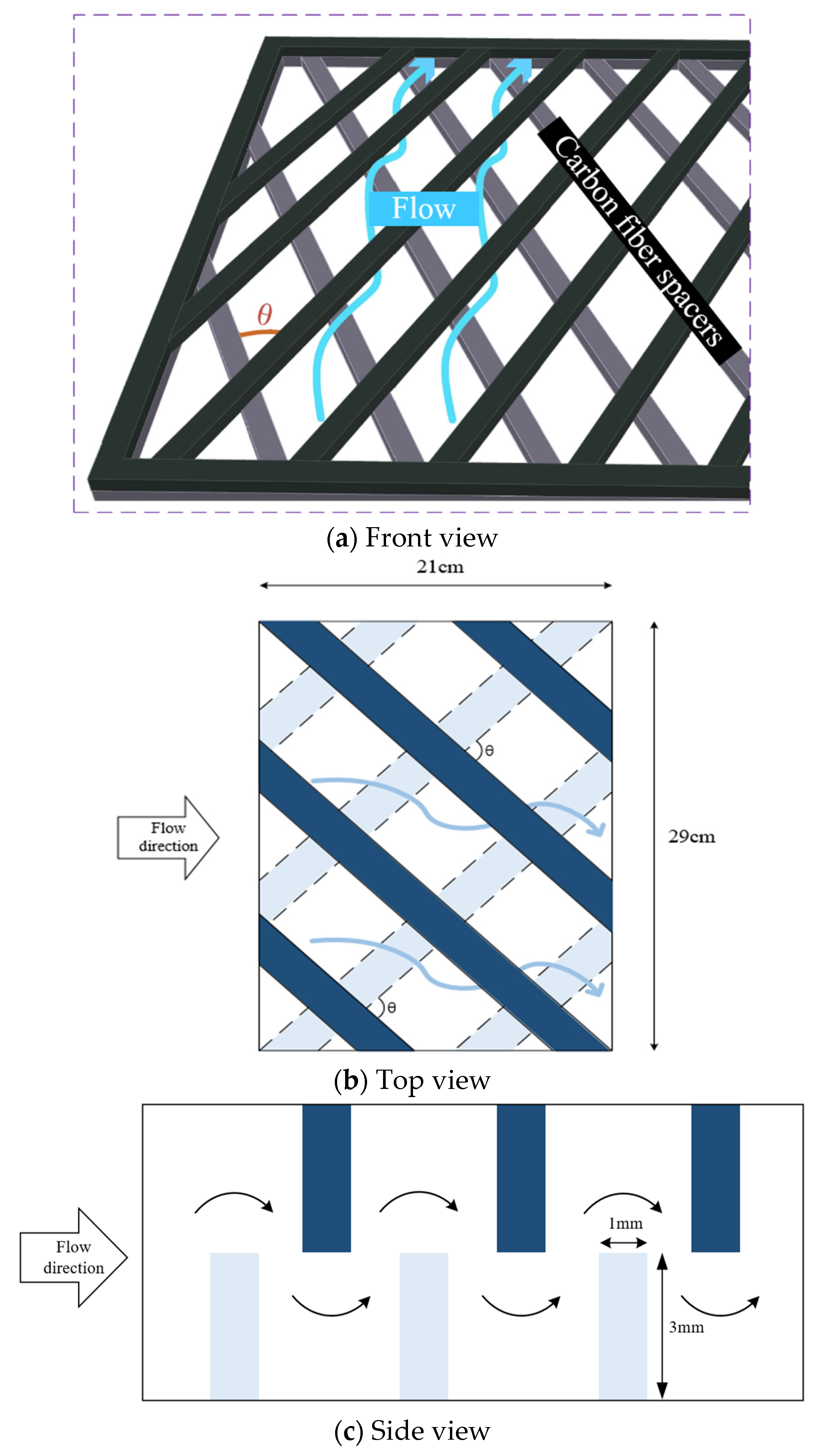
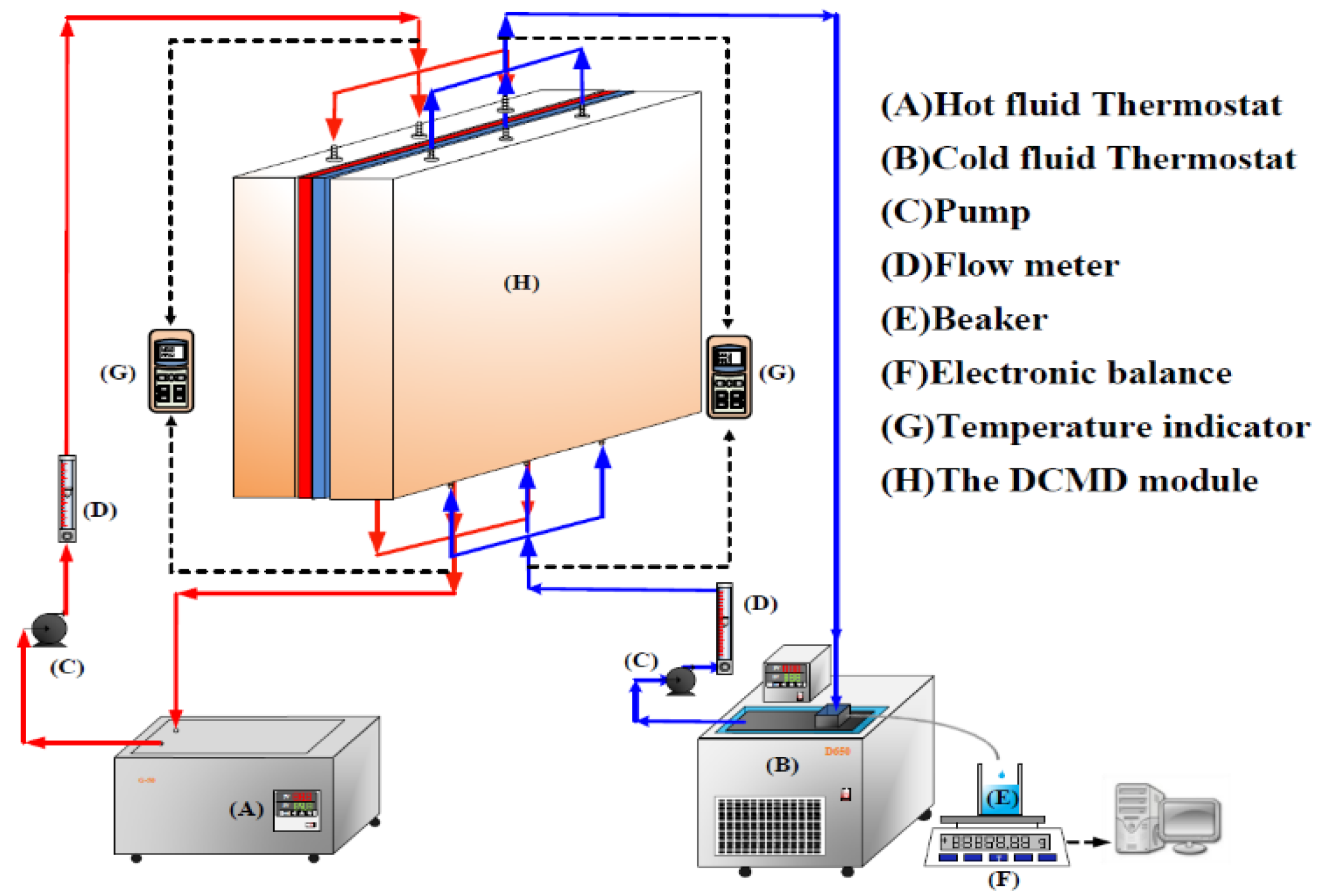
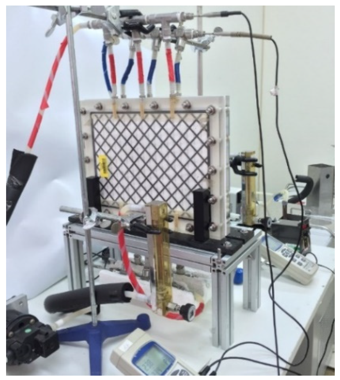
3. Experimental Apparatus and Procedures
4. Flux Enhancement Factor and Power Consumption Increment
5. Results and Discussion
6. Conclusions
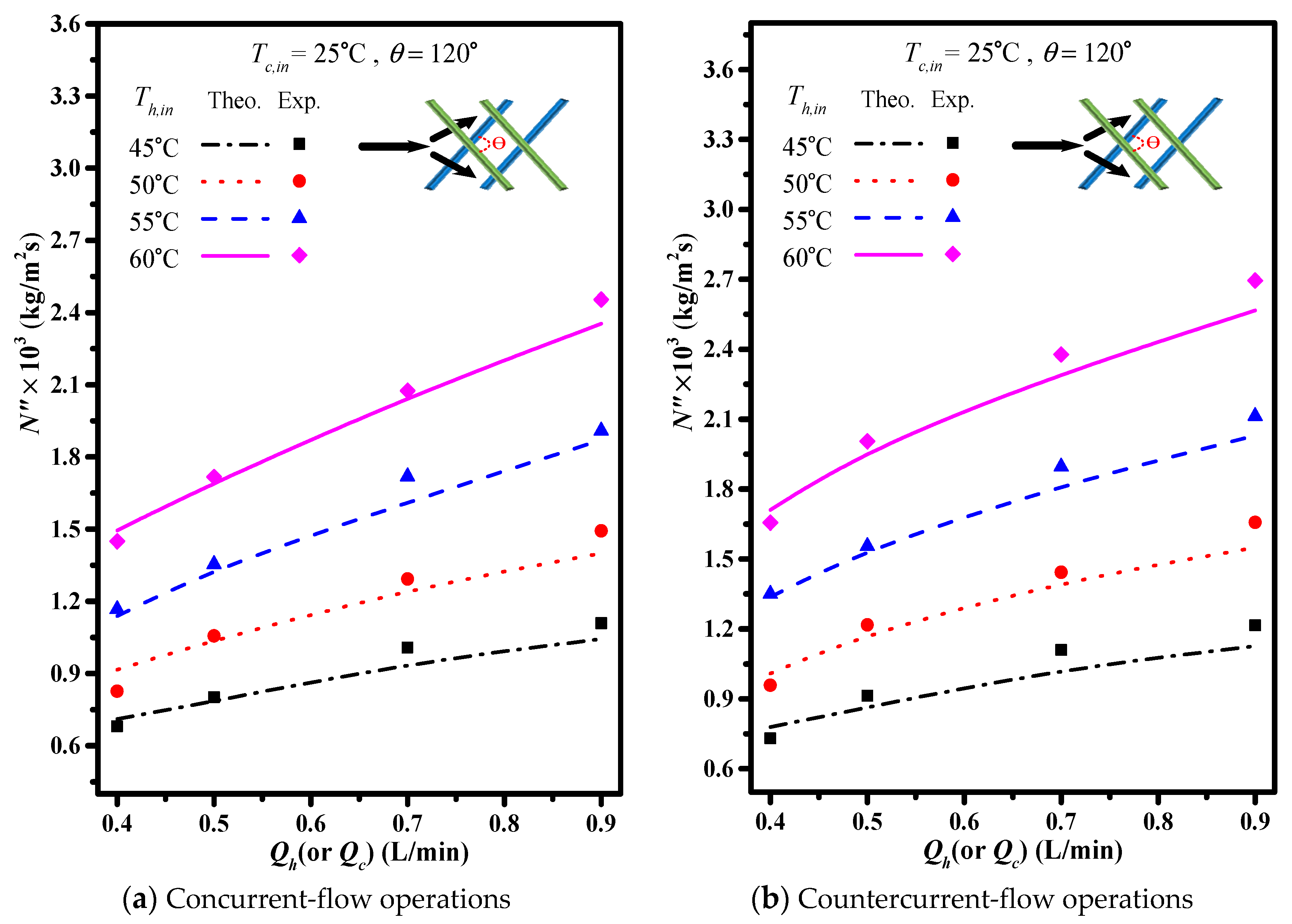
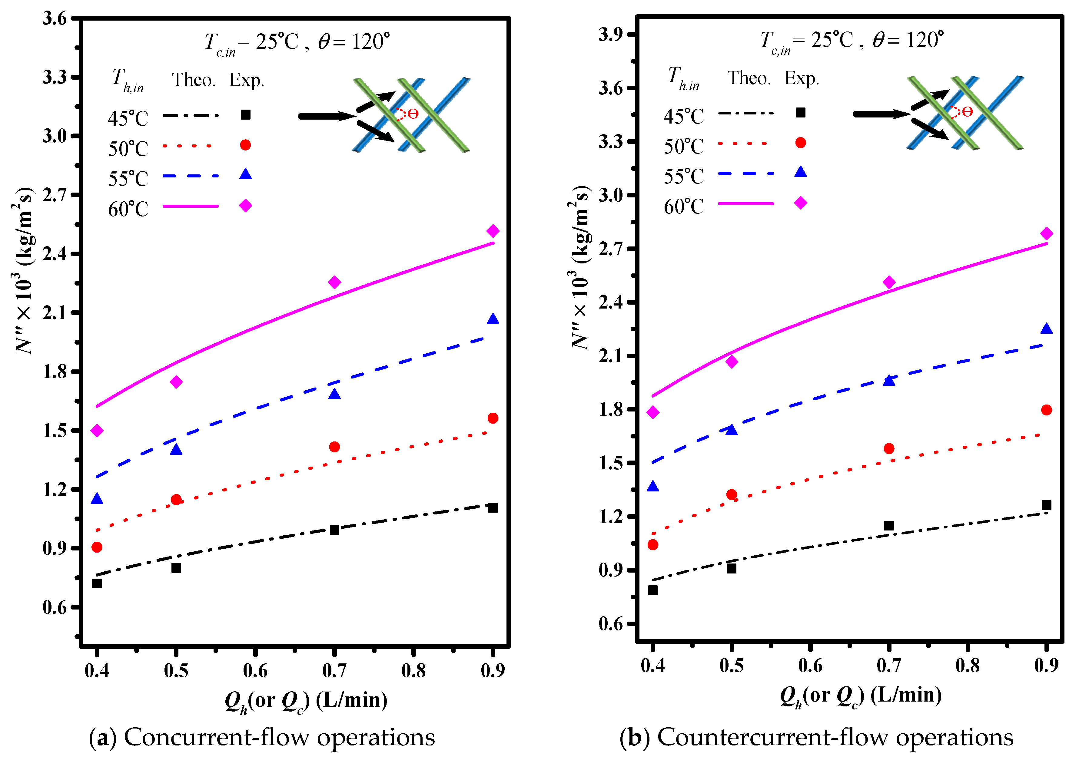
- The permeate flux increases with the increase of the volumetric flow rate.
- Higher inlet saline temperature yields higher permeate flux productivity.
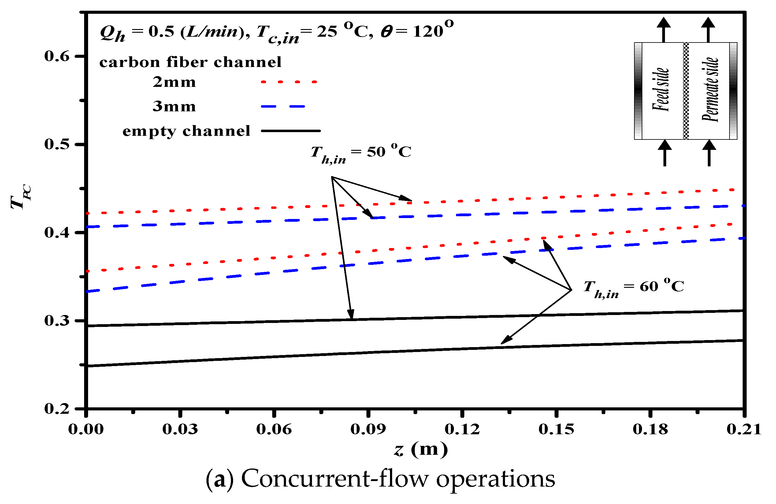
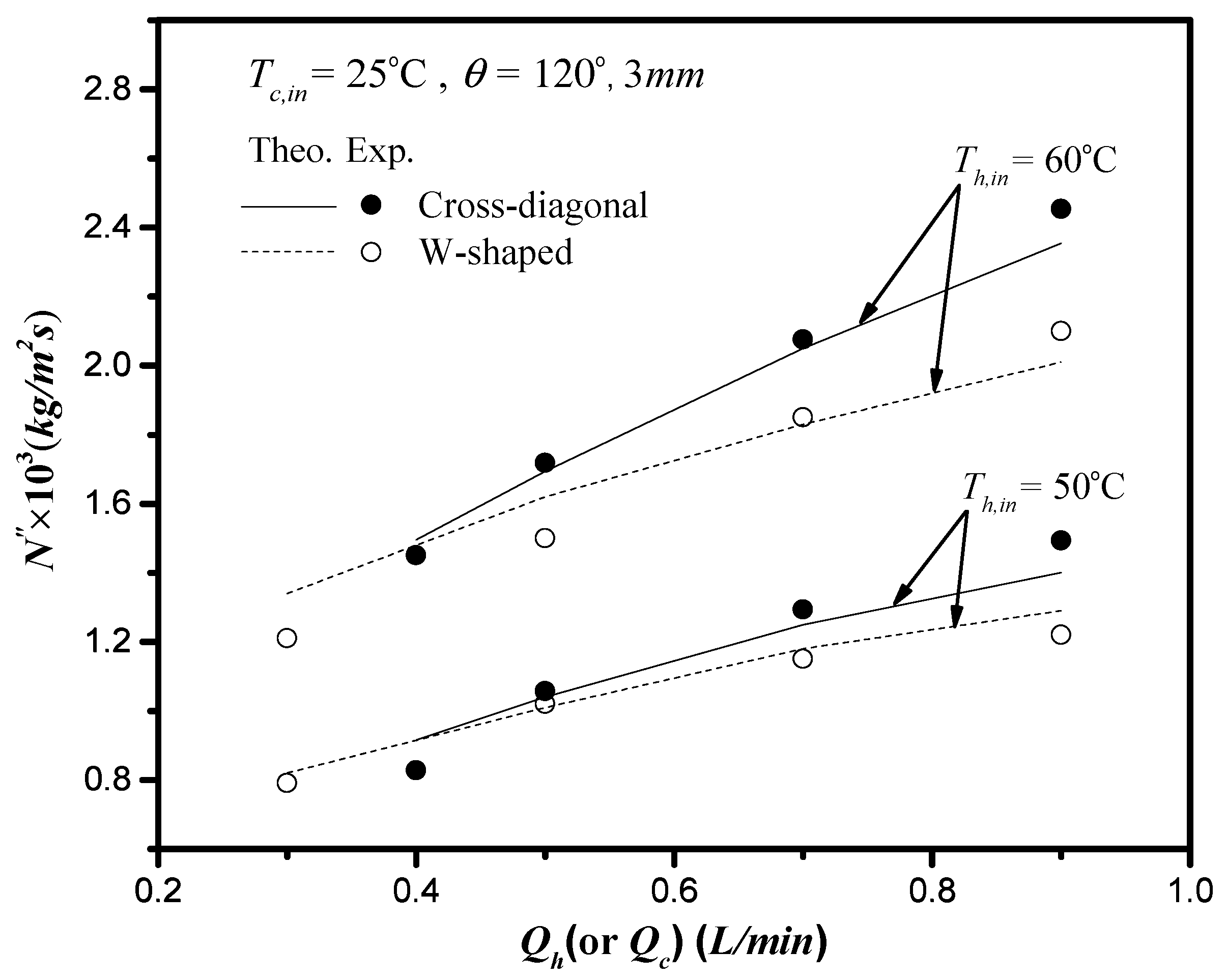
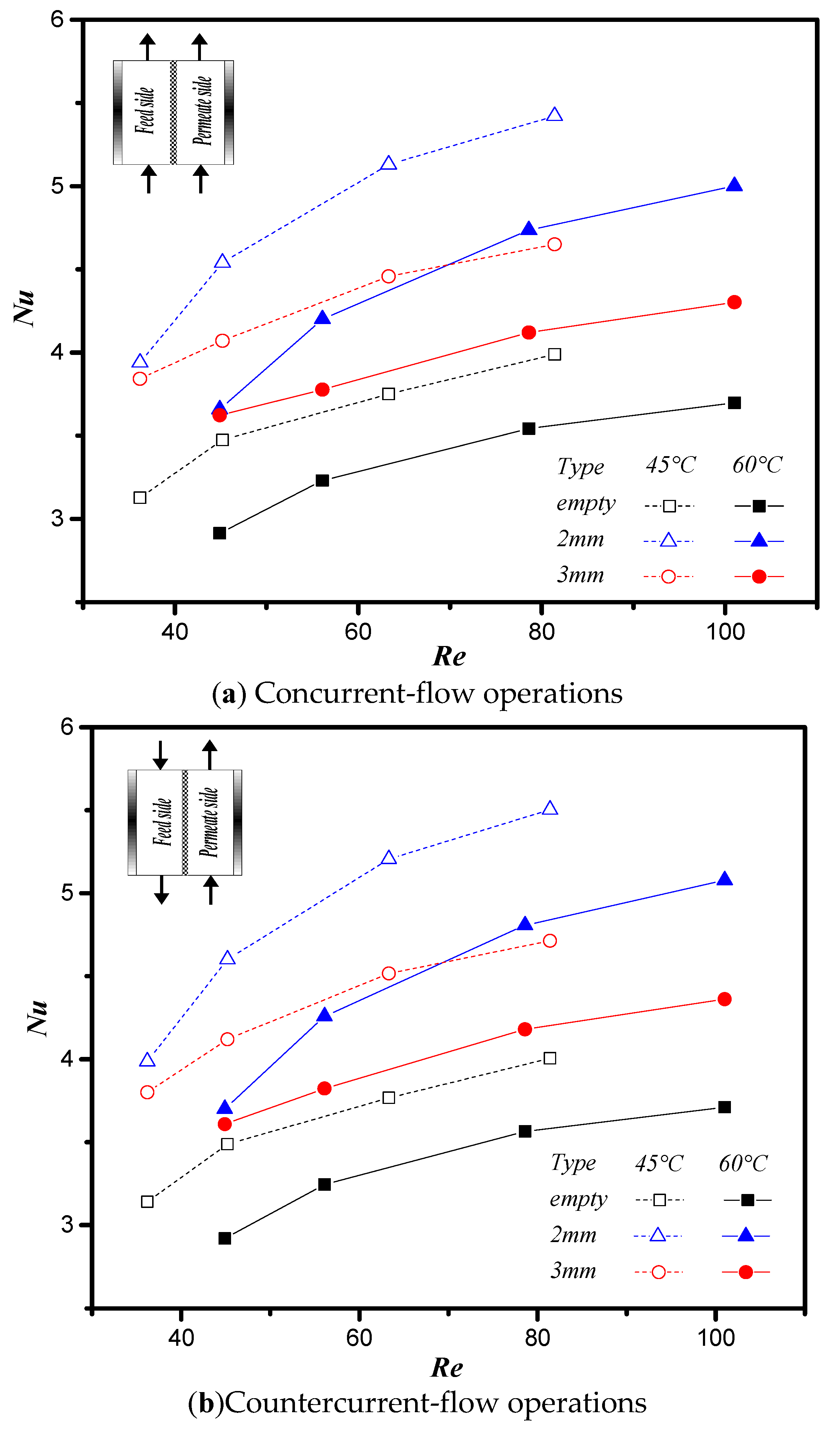
- The permeate flux enhancement is obtained by inserting net-like cross-diagonal carbon-fiber spacers where the enhancement of the 2 mm slot opening is higher than that of the 3 mm one.
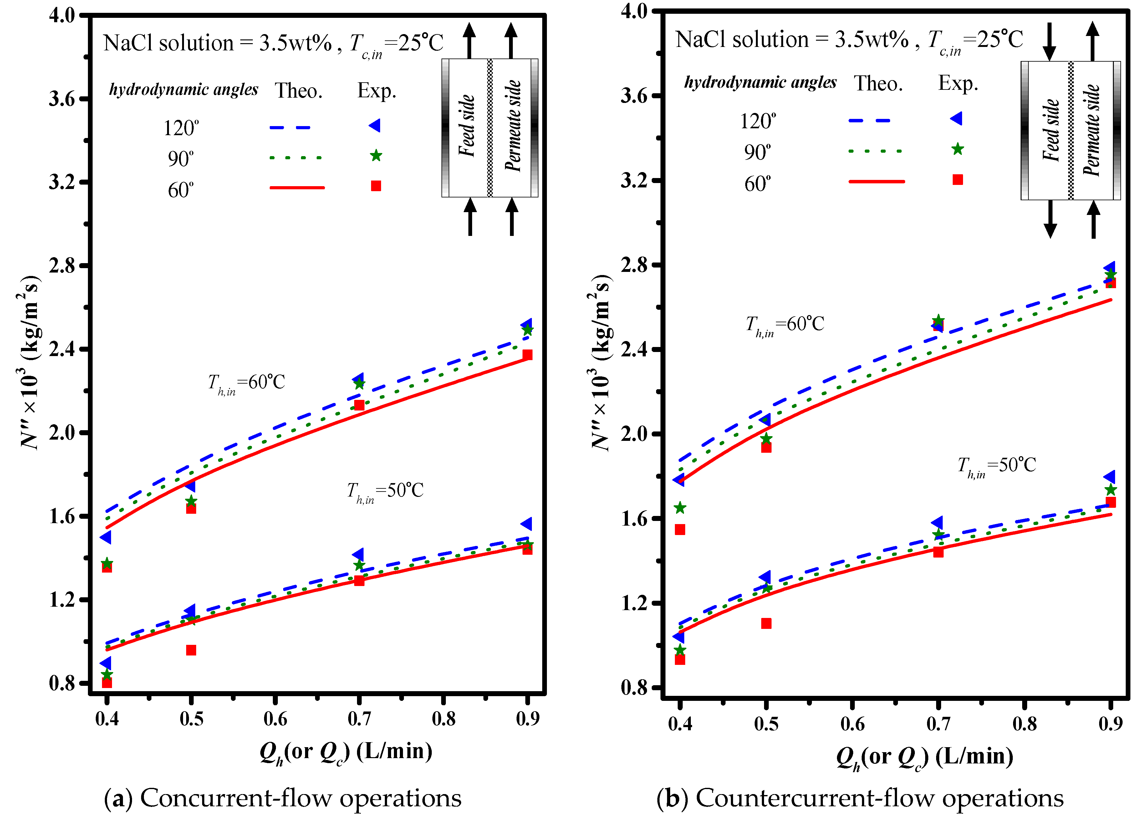
- The permeate flux increases with increasing hydrodynamic angle in the slot of the cross-diagonal carbon-fiber spacers.
- A maximum of 45.1% permeate flux enhancement was found in the device with cross-diagonal carbon-fiber spacers compared to that in the empty channel device under countercurrent-flow operations of 120° hydrodynamic angle.
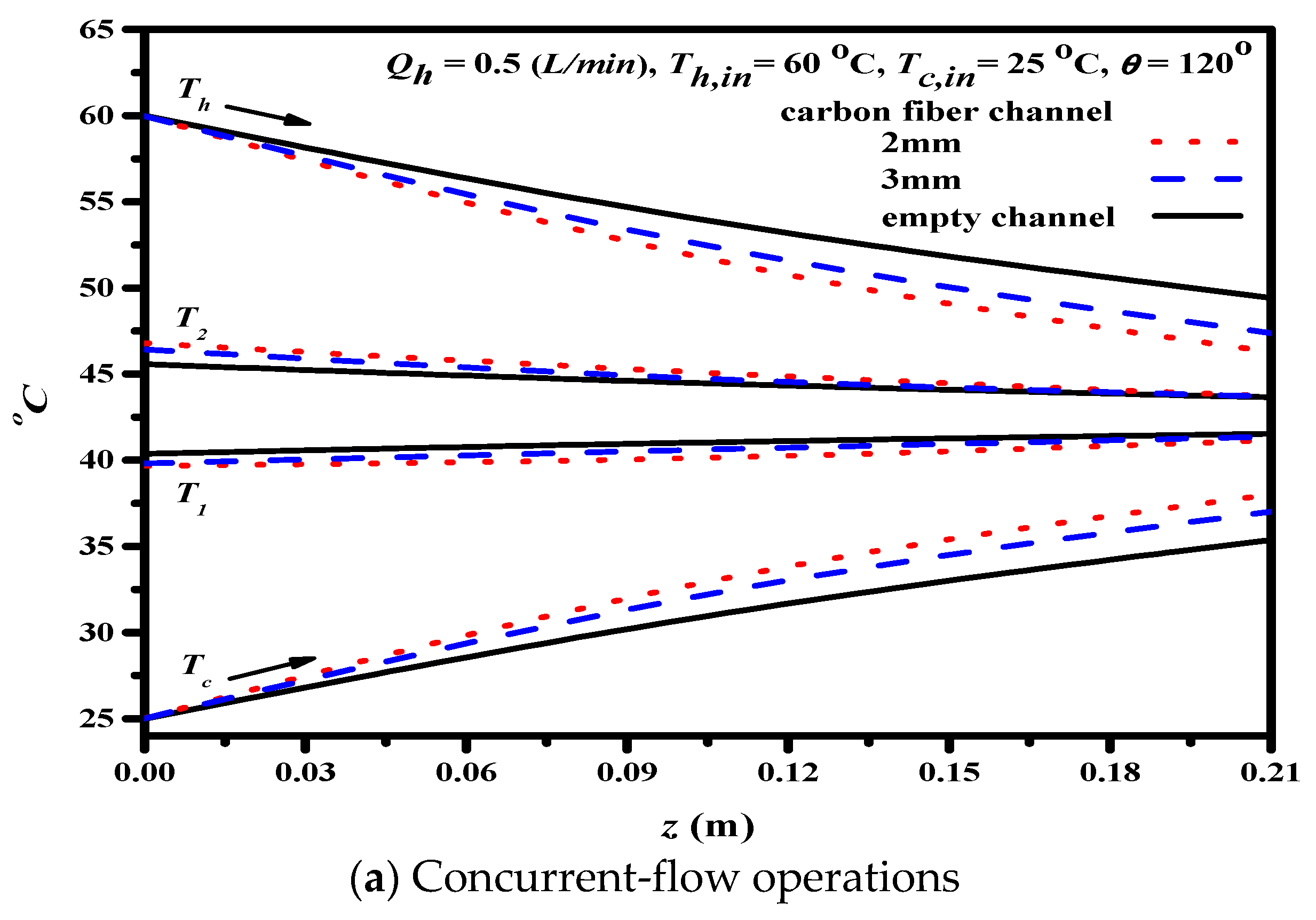
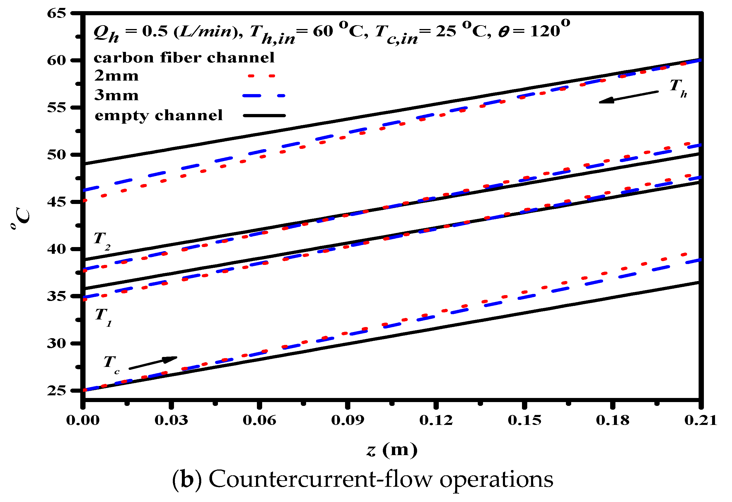
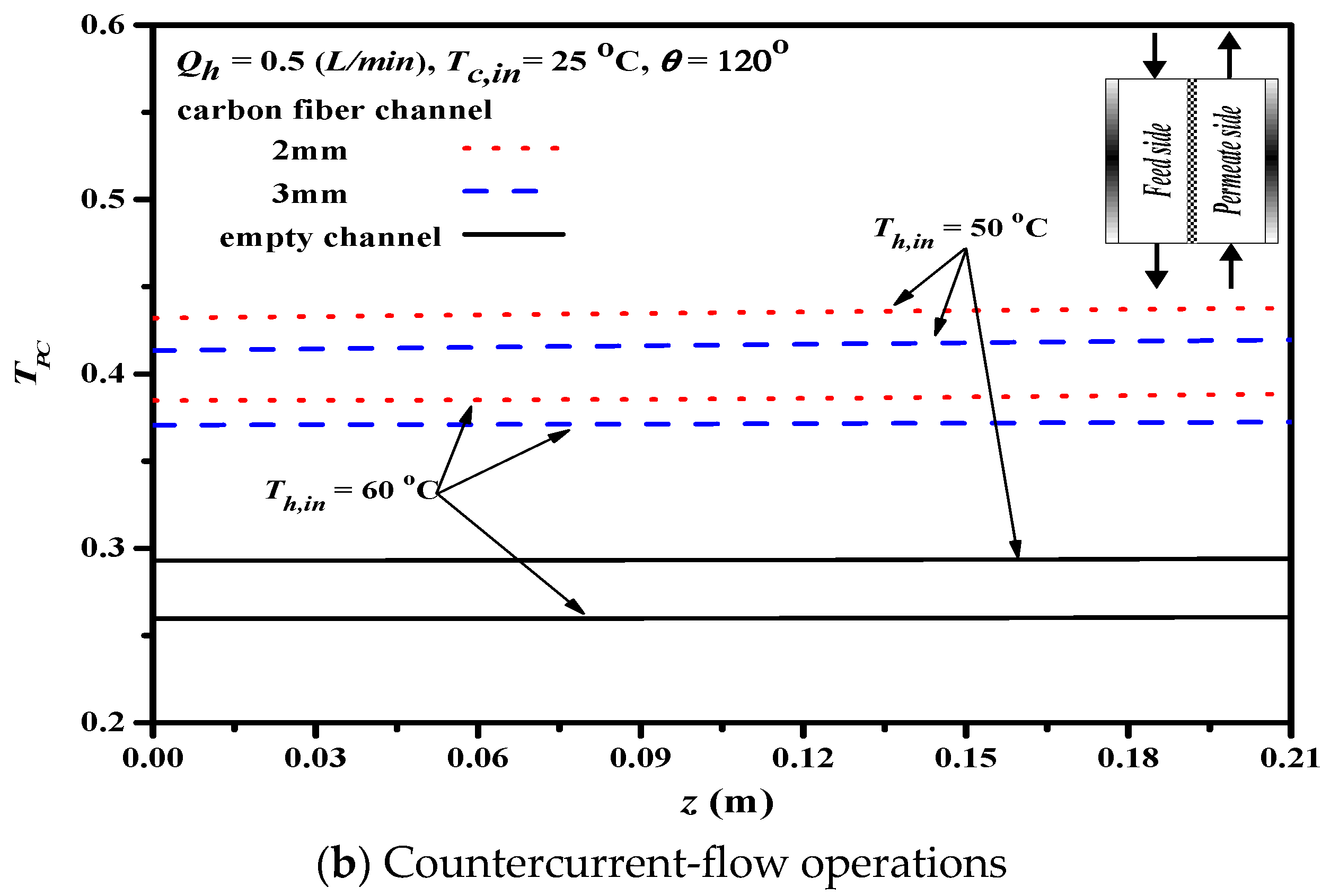
- A more considerable permeate flux was achieved in countercurrent-flow operations than in concurrent-flow operations due to the larger temperature gradient for countercurrent-flow operations.
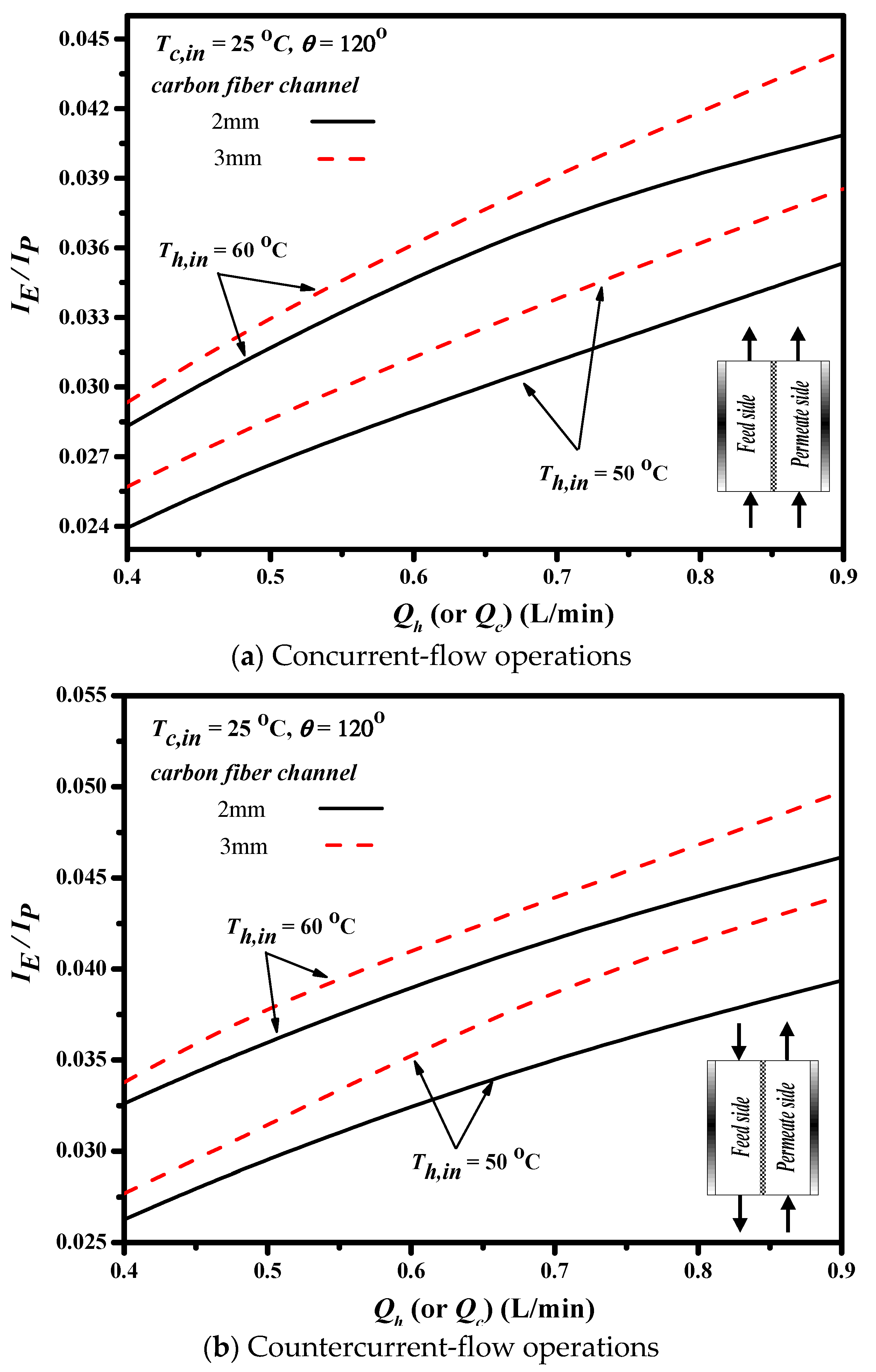
- The economic consideration of for permeate flux enhancement to power consumption increment concluded that the power utilization is more effective for the channel with cross-diagonal carbon-fiber spacers in higher hot saline water flow rate, and the ratio of for the 3 mm slot opening is higher than that of the 2 mm one.
Author Contributions
Funding
Acknowledgments
Conflicts of Interest
Abbreviations
| Water activity in NaCl solution | |
| Heat capacity of cold fluid (J kg−1 K−1) | |
| Heat capacity of hot fluid (J kg−1 K−1) | |
| Mass transfer coefficient of membrane (kg m−2 Pa−1 s−1) | |
| Equivalent hydraulic diameter of empty channel (m) | |
| Equivalent hydraulic diameter of hot side (m) | |
| Equivalent hydraulic diameter of cold side (m) | |
| Height of flow channel (m) | |
| dp | Height of carbon-fiber spacers |
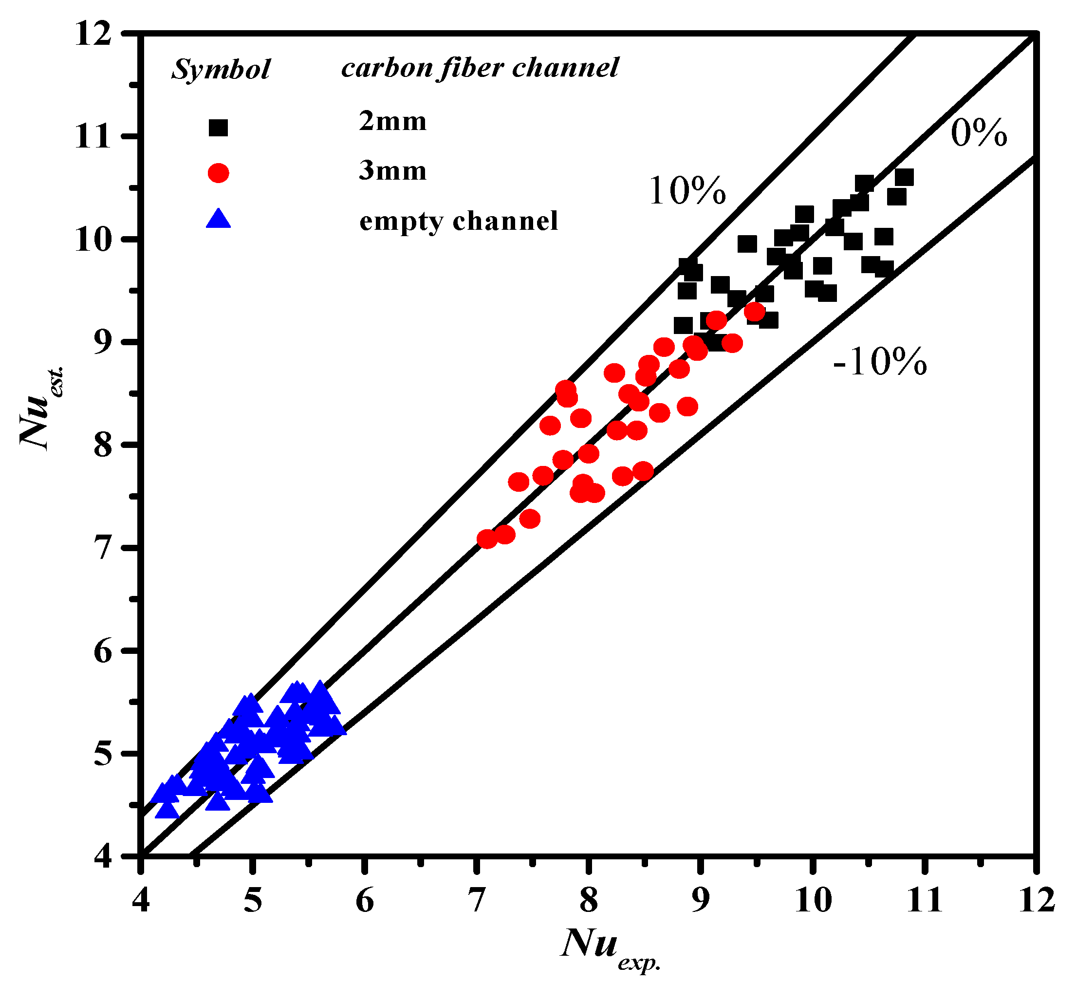
| E | Deviation of experimental results from the theoretical predictions |
| Fanning friction factor | |
| Convection coefficient of cold fluid (W m−2 K−1) | |
| Convection coefficient of hot fluid (W m−2 K−1) | |
| Hydraulic dissipate energy (J kg−1), | |
| Thermal convection coefficient of membrane (W m−2 K−1) | |
| Increased percentage of permeate flux | |
| Raised percentage of hydraulic loss | |
| Axial distance (m) | |
| Thermal conductivity coefficient of hot saline feed (W m−1 K−1) | |
| Thermal conductivity coefficient of the vapor in the membrane pore (W m−1 K−1) | |
| Thermal conductivity coefficient of the solid membrane material (W m−1 K−1) | |
| Friction loss of conduits (J kg−1) | |
| Molecular weight of water (kg mol−1) | |
| Mass flow rate (kg s−1) | |
| Permeate flux (kg m−2 h−1) | |
| Nusselt number | |
| Nusselt number of the turbulence promoter | |
| Dimensionless Nusselt number for laminar flow | |
| Pressure (Pa) | |
| Saturation vapor pressure in the cold feed flow side (Pa) | |
| Saturation vapor pressure in the hot feed flow side (Pa) | |
| Saturated vapor pressure of pure water (Pa) | |
| Prandtl number | |
| Heat transfer rate (W/m2) | |
| Heat transfer rate between cooling plate and cold fluid (W/m2) | |
| Heat transfer rate between hot fluid and membrane surface (W/m2) | |
| Heat transfer rate between membrane surface of hot fluid and air gap (W/m2) | |
| Volumetric flow rate (m3 s−1) | |
| Gas constant (8.314 J mol−1 K−1) | |
| Re | Reynolds number |
| Temperature (°C) | |
| Mean temperature in membrane (°C) | |
| Average velocity (m s−1) | |
| Width of flow channel | |
| Width of carbon-fiber spacers | |
| Natural log mean mole fraction of air | |
| Liquid mole fraction of NaCl | |
| Liquid mole fraction of water | |
| Axial coordinate along the flow direction (m) | |
| Greek letters | |
| Heat transfer enhancement factor | |
| Aspect ratio of the channel | |
| Vapor pressure difference of membrane (Pa) | |
| Thickness of membrane (µm) | |
| Membrane porosity | |
| Channel voidage | |
| Latent heat of water (J/kg) | |
| Fluid viscosity (kg s−1 m−1) | |
| Density (kg m−3) | |
| Temperature polarization coefficients | |
| Subscripts | |
| 1 | Membrane surface on cold feed side |
| 2 | Membrane surface on hot feed side |
| h | In the hot feed flow channel |
| c | In the cold feed flow channel |
| carbon fiber | Inserting cross-diagonal carbon-fiber spacers |
| empty | Inserting nylon fiber as supporters |
| exp | Experimental results |
| in | Inlet |
| lam | Empty channel |
| out | Outlet |
| theo | Theoretical predictions |
| Superscripts | |
| E | The channel with inserting cross-diagonal carbon-fiber spacers |
References
- Drioli, E.; Ali, A.; Macedonio, F. Membrane distillation: Recent developments and perspectives. Desalination 2015, 356, 56–84. [Google Scholar] [CrossRef]
- Lawson, K.W.; Lloyd, D.R. Membrane distillation. J. Membr. Sci. 1997, 124, 1–25. [Google Scholar] [CrossRef]
- Martínez-Díez, L.; Vázquez-González, M.; Florido-Díaz, F. Study of membrane distillation using channel spacers. J. Membr. Sci. 1998, 144, 45–56. [Google Scholar] [CrossRef]
- Alkhudhiri, A.; Darwish, N.; Hilal, N. Membrane distillation: A comprehensive review. Desalination 2012, 287, 2–18. [Google Scholar] [CrossRef]
- Lawson, K.W.; Lloyd, D.R. Membrane distillation. II. direct contact MD. J. Membr. Sci. 1996, 120, 123–133. [Google Scholar] [CrossRef]
- Martínez-Díez, L.; Vázquez-González, M.I. Effects of polarization on mass transport through hydrophobic porous membranes. Ind. Eng. Chem. Res. 1998, 37, 4128–4135. [Google Scholar] [CrossRef]
- Phattaranawik, J.; Jiraratananon, R.; Fane, A. Effects of net-type spacers on heat and mass transfer in direct contact membrane distillation and comparison with ultrafiltration studies. J. Membr. Sci. 2003, 217, 193–206. [Google Scholar] [CrossRef]
- Santos, J.; Geraldes, V.; Velizarov, S.; Crespo, J. Investigation of flow patterns and mass transfer in membrane module channels filled with flow-aligned spacers using computational fluid dynamics (CFD). J. Membr. Sci. 2007, 305, 103–117. [Google Scholar] [CrossRef]
- Wang, T.; Zhang, Z.; Ren, X.; Qin, L.; Zheng, D.; Li, J. Direct observation of single- and two-phase flows in spacer filled membrane modules. Sep. Purif. Technol. 2014, 125, 275–283. [Google Scholar] [CrossRef]
- Ho, C.D.; Chang, H.; Chang, C.L.; Huang, C.H. Theoretical and experimental studies of performance enhancement with roughened surface in direct contact membrane distillation desalination. J. Membr. Sci. 2013, 433, 160–166. [Google Scholar] [CrossRef]
- Yang, X.; Yu, H.; Wang, R.; Fane, A.G. Optimization of microstructured hollow fiber design for membrane distillation applications using CFD modeling. J. Membr. Sci. 2012, 421–422, 258–270. [Google Scholar] [CrossRef] [Green Version]
- Lee, J.-G.; Kim, Y.-D.; Kim, W.-S.; Francis, L.; Amy, G.; Ghaffour, N. Performance modeling of direct contact membrane distillation (DCMD) seawater desalination process using a commercial composite membrane. J. Membr. Sci. 2015, 478, 85–95. [Google Scholar] [CrossRef] [Green Version]
- Warner, S.B. Fiber Science; Princeton-Hall: Englewood Cliffs, NJ, USA, 1995. [Google Scholar]
- Schofield, R.W.; Fane, A.G.; Fell, C.J.D. Gas and vapor transport through microporous membranes. I. Knudsen-Poiseuille transition. J. Membr. Sci. 1990, 53, 159–171. [Google Scholar] [CrossRef]
- Iversen, S.B.; Bhatia, V.K.; Dam-Jphasen, K.; Jonsson, G. Characterization of microporous membranes for use in membrane contactors. J. Membr. Sci. 1997, 130, 205–217. [Google Scholar] [CrossRef]
- Phattaranawik, J.; Jiraratananon, R.; Fane, A.G. Heat transport and membrane distillation coefficients in direct contact membrane distillation. J. Membr. Sci. 2003, 212, 177–193. [Google Scholar] [CrossRef]
- Phattaranawik, J.; Jiraratananon, R.; Fane, A.G.; Halim, C. Mass flux enhancement using spacer filled channels in direct contact membrane distillation. J. Membr. Sci. 2001, 187, 193–201. [Google Scholar] [CrossRef]
- Welty, J.R.; Wicks, C.E.; Wilson, R.E. Fundamentals of Momentum, Heat, and Mass Transfer, 3rd ed.; John Wiley & Sons: New York, NY, USA, 1984. [Google Scholar]
- Kakac, S.; Shah, R.K.; Aung, W. Handbook of Single-Phase Convective Heat Transfer; Wiley: New York, NY, USA, 1987. [Google Scholar]
- Shakaib, M.; Hasani, S.M.F.; Ahmed, I.; Yunus, R.M. A CFD study on the effect of spacer orientation on temperature polarization in membrane distillation modules. Desalination 2012, 284, 332–340. [Google Scholar] [CrossRef]
- Ho, C.D.; Chen, L.; Lai, J.Y.; Ng, C.A. Theoretical and experimental studies of direct contact membrane distillation modules with inserting W-shaped carbon-fiber spacers. Desalination Water Treat. 2017, 71, 32–44. [Google Scholar] [CrossRef] [Green Version]


(m3 s−1) | (a) Cross-Diagonal Carbon-Fiber Spacers (2 mm) | |||||||||
kg m−2 s−1 | kg m−2 s−1 | (%) | kg m−2 s−1 | kg m−2 s−1 | (%) | kg m−2 s−1 | kg m−2 s−1 | (%) | ||
| 45 | 6.67 | 0.69 | 0.74 | 6.33 | 0.69 | 0.75 | 8.18 | 0.72 | 0.77 | 5.77 |
| 8.33 | 0.80 | 0.83 | 3.90 | 0.80 | 0.85 | 5.09 | 0.80 | 0.80 | 7.54 | |
| 11.7 | 0.89 | 0.97 | 8.12 | 0.93 | 0.98 | 5.60 | 0.99 | 1.00 | 1.01 | |
| 15.0 | 1.00 | 1.09 | 8.08 | 1.06 | 1.10 | 3.82 | 1.11 | 1.12 | 1.62 | |
| 50 | 6.67 | 0.88 | 0.96 | 8.37 | 0.89 | 0.98 | 8.56 | 0.91 | 0.99 | 8.78 |
| 8.33 | 1.05 | 1.10 | 4.64 | 1.10 | 1.12 | 1.37 | 1.15 | 1.14 | 0.94 | |
| 11.7 | 1.29 | 1.30 | 0.69 | 1.36 | 1.32 | 3.49 | 1.42 | 1.35 | 5.23 | |
| 15.0 | 1.44 | 1.46 | 1.25 | 1.46 | 1.48 | 0.94 | 1.56 | 1.50 | 4.51 | |
| 55 | 6.67 | 1.09 | 1.20 | 8.90 | 1.10 | 1.22 | 9.87 | 1.15 | 1.26 | 9.26 |
| 8.33 | 1.29 | 1.39 | 7.67 | 1.33 | 1.45 | 8.01 | 1.40 | 1.47 | 5.24 | |
| 11.7 | 1.54 | 1.68 | 8.18 | 1.59 | 1.71 | 7.27 | 1.68 | 1.75 | 4.06 | |
| 15.0 | 1.80 | 1.90 | 5.53 | 1.82 | 1.93 | 5.74 | 2.06 | 1.98 | 4.00 | |
| 60 | 6.67 | 1.41 | 1.55 | 9.04 | 1.44 | 1.59 | 9.56 | 1.50 | 1.62 | 7.65 |
| 8.33 | 1.64 | 1.79 | 8.56 | 1.67 | 1.83 | 8.54 | 1.75 | 1.86 | 6.21 | |
| 11.7 | 2.13 | 2.09 | 1.77 | 2.23 | 2.13 | 4.77 | 2.25 | 2.19 | 2.92 | |
| 15.0 | 2.37 | 2.38 | 0.24 | 2.49 | 2.43 | 2.46 | 2.52 | 2.46 | 2.46 | |
() | (m3 s−1) | (b) Cross-Diagonal Carbon-Fiber Spacers (2 mm) | ||||||||
kg m−2 s−1 | kg m−2 s−1 | (%) | kg m−2 s−1 | kg m−2 s−1 | (%) | kg m−2 s−1 | kg m−2 s−1 | (%) | ||
| 45 | 6.67 | 0.74 | 0.81 | 8.74 | 0.76 | 0.83 | 8.75 | 0.79 | 0.85 | 6.79 |
| 8.33 | 0.84 | 0.92 | 9.04 | 0.87 | 0.94 | 7.38 | 0.91 | 0.96 | 5.55 | |
| 11.7 | 1.04 | 1.06 | 2.55 | 1.07 | 1.07 | 0.33 | 1.15 | 1.10 | 4.49 | |
| 15.0 | 1.14 | 1.18 | 3.26 | 1.23 | 1.19 | 2.66 | 1.26 | 1.22 | 3.66 | |
| 50 | 6.67 | 0.97 | 1.06 | 8.50 | 9.78 | 1.07 | 8.63 | 1.04 | 1.10 | 5.56 |
| 8.33 | 1.14 | 1.26 | 9.26 | 1.27 | 1.27 | 0.12 | 1.32 | 1.31 | 1.31 | |
| 11.7 | 1.44 | 1.47 | 1.69 | 1.52 | 1.46 | 4.09 | 1.58 | 1.52 | 3.82 | |
| 15.0 | 1.68 | 1.62 | 3.49 | 1.74 | 1.64 | 5.87 | 1.80 | 1.66 | 8.00 | |
| 55 | 6.67 | 1.29 | 1.41 | 8.86 | 1.34 | 1.45 | 7.77 | 1.36 | 1.50 | 9.37 |
| 8.33 | 1.48 | 1.62 | 8.73 | 1.55 | 1.69 | 7.86 | 1.68 | 1.72 | 2.60 | |
| 11.7 | 1.80 | 1.90 | 5.60 | 1.85 | 1.94 | 4.82 | 1.95 | 1.99 | 1.73 | |
| 15.0 | 2.12 | 2.07 | 2.42 | 2.14 | 2.10 | 2.08 | 2.25 | 2.16 | 3.81 | |
| 60 | 6.67 | 1.70 | 1.79 | 5.27 | 1.71 | 1.83 | 6.89 | 1.78 | 1.88 | 4.88 |
| 8.33 | 1.94 | 2.07 | 6.68 | 1.98 | 2.11 | 6.44 | 2.07 | 2.15 | 4.03 | |
| 11.7 | 2.51 | 2.35 | 6.73 | 2.54 | 2.40 | 5.69 | 2.51 | 2.46 | 2.29 | |
| 15.0 | 2.71 | 2.66 | 1.85 | 2.75 | 2.70 | 1.97 | 2.79 | 2.73 | 2.07 | |
| (a) Effects of Hydrodynamic Angles on Flux Enhancement for Concurrent Flow | ||||||||||
() | (m3 s−1) | Empty Channel | 2 mm | 3 mm | ||||||
kg m−2s−1 | kg m−2s−1 | kg m−2s−1 | kg m−2s−1 | kg m−2s−1 | ||||||
| 50 | 6.67 | 0.81 | 0.96 | 18.7 | 0.98 | 20.4 | 0.99 | 22.6 | 0.97 | 19.8 |
| 8.33 | 0.91 | 1.10 | 21.6 | 1.12 | 23.7 | 1.14 | 25.6 | 1.10 | 21.7 | |
| 11.7 | 1.03 | 1.30 | 26.3 | 1.32 | 28.0 | 1.35 | 30.7 | 1.28 | 24.6 | |
| 15.0 | 1.11 | 1.46 | 31.4 | 1.48 | 33.1 | 1.50 | 34.7 | 1.43 | 29.0 | |
| 60 | 6.67 | 1.27 | 1.55 | 21.7 | 1.59 | 25.1 | 1.62 | 27.8 | 1.54 | 21.3 |
| 8.33 | 1.43 | 1.79 | 25.1 | 1.83 | 27.8 | 1.86 | 30.3 | 1.78 | 24.2 | |
| 11.7 | 1.60 | 2.09 | 30.1 | 2.13 | 33.2 | 2.19 | 36.9 | 2.07 | 29.6 | |
| 15.0 | 1.75 | 2.38 | 35.6 | 2.43 | 38.6 | 2.46 | 40.0 | 2.35 | 34.1 | |
| (b) Effects of Hydrodynamic Angles on Flux Enhancement for Countercurrent Flow | ||||||||||
() | (m3 s−1) | Empty channel | 2 mm | 3 mm | ||||||
kg m−2 s−1 | kg m−2 s−1 | kg m−2 s−1 | (%) | kg m−2 s−1 | (%) | kg m−2 s−1 | (%) | |||
| 50 | 6.67 | 0.88 | 1.06 | 21.4 | 1.07 | 22.2 | 1.10 | 25.9 | 1.06 | 21.0 |
| 8.33 | 1.01 | 1.26 | 24.6 | 1.27 | 26.1 | 1.31 | 29.2 | 1.25 | 23.7 | |
| 11.7 | 1.13 | 1.47 | 29.7 | 1.46 | 29.4 | 1.52 | 34.7 | 1.46 | 29.5 | |
| 15.0 | 1.20 | 1.62 | 35.0 | 1.64 | 36.6 | 1.66 | 38.7 | 1.60 | 33.2 | |
| 60 | 6.67 | 1.42 | 1.78 | 25.0 | 1.83 | 29.0 | 1.88 | 32.1 | 1.78 | 25.5 |
| 8.33 | 1.59 | 2.05 | 28.9 | 2.10 | 31.9 | 2.15 | 35.5 | 2.05 | 28.7 | |
| 11.7 | 1.74 | 2.35 | 35.3 | 2.40 | 38.9 | 2.46 | 41.1 | 2.32 | 33.1 | |
| 15.0 | 1.88 | 2.66 | 41.7 | 2.70 | 43.6 | 2.73 | 45.1 | 2.58 | 37.3 | |
Publisher’s Note: MDPI stays neutral with regard to jurisdictional claims in published maps and institutional affiliations. |
© 2021 by the authors. Licensee MDPI, Basel, Switzerland. This article is an open access article distributed under the terms and conditions of the Creative Commons Attribution (CC BY) license (https://creativecommons.org/licenses/by/4.0/).
Share and Cite
Ho, C.-D.; Chen, L.; Lim, J.-W.; Lin, P.-H.; Lu, P.-T. Distillate Flux Enhancement of Direct Contact Membrane Distillation Modules with Inserting Cross-Diagonal Carbon-Fiber Spacers. Membranes 2021, 11, 973. https://doi.org/10.3390/membranes11120973
Ho C-D, Chen L, Lim J-W, Lin P-H, Lu P-T. Distillate Flux Enhancement of Direct Contact Membrane Distillation Modules with Inserting Cross-Diagonal Carbon-Fiber Spacers. Membranes. 2021; 11(12):973. https://doi.org/10.3390/membranes11120973
Chicago/Turabian StyleHo, Chii-Dong, Luke Chen, Jun-Wei Lim, Po-Hung Lin, and Pin-Tsen Lu. 2021. "Distillate Flux Enhancement of Direct Contact Membrane Distillation Modules with Inserting Cross-Diagonal Carbon-Fiber Spacers" Membranes 11, no. 12: 973. https://doi.org/10.3390/membranes11120973
APA StyleHo, C.-D., Chen, L., Lim, J.-W., Lin, P.-H., & Lu, P.-T. (2021). Distillate Flux Enhancement of Direct Contact Membrane Distillation Modules with Inserting Cross-Diagonal Carbon-Fiber Spacers. Membranes, 11(12), 973. https://doi.org/10.3390/membranes11120973