1. Introduction
With the reduction of land resources, the exploration of marine resources has become particularly important. An underwater vehicle is the main tool to explore the marine resource, and the complex submarine environment requires high flexibility and controllability of the vehicle [
1,
2,
3,
4]. At present, most layout schemes of underwater vehicle are as follows:
(1) Multi-thruster distributed layout
Multiple thrusters are installed in different positions of the vehicle to realize the multi-degree-of-freedom maneuvering motion, including the rotation and pitch. Because of its favorable operability and flexibility, this layout scheme is widely used in underwater vehicles with high mobility requirements. A typical case is the underwater mine-clearing vehicle named double-head eagle launched by SAAB AB (Saab-ScaniaAB) company, which can achieve omni-directional control at zero speed and backward motion. However, some of these thrusters are invocated only at turning and lie idle most of the time, which causes a waste of the mechanism resource and the increase of volume and underwater sailing resistance [
5,
6].
(2) Vector water-jet propulsion system
This method controls the thrust direction by changing propellers’ high-speed jet direction, combining the advantages of water-jet propulsion and thrust-vectoring. For example, the water-jet propulsion systems manufactured by the Hamilton corporation in New Zealand and the Kamewa corporation in Sweden, control astern guide units and steering pipes to produce water jets in different directions, so that the turning and pitch and other attitudes could be realized [
7,
8]. However, the actual propulsive efficiency of the water-jet propulsion system is affected by the thrust loss of the propulsion pump and pipeline. Compared with the propeller propulsion, the energy conversion rate is lower [
9].
(3) Vector propeller propulsion system
This system uses a single propeller, in which thrust directions are changed by the thrusters’ control to achieve vector propulsion, such as the full deflection vector thruster based on the spatial linkage and universal joint proposed by Rinaldo and Emanuele [
10,
11], and a similar mechanism, the full deflection vector thruster with single rotator by Luwei Chen and Zhaohui Zhou [
12]. However, these kinds of mechanisms have problems such as redundancy of degree of freedom and relatively complex control [
13]. Tao Liu, Yuli Hu, et al. designed a 3-SPS-S (Spherical-Prismatic-Spherical-Spherical) parallel manipulator with passive constraining spherical joints to drive the underwater vehicle [
14]. Ba Xin and Luo Xiaohui used a 3-RPS (Revolute-Prismatic-Spherical) parallel mechanism with hydraulic driven to realize the attitude adjustment of the vehicle [
15]. The above thrusters all use the external actuator, which puts forward high request to the sealing characteristics of the propulsion device. Meanwhile, the position of the propeller varies greatly during the attitude adjustment, which goes against stability of the underwater vehicle [
16].
On the basis of the above analysis, a RS+2PRS (Revolute-Spherical+ Prismatic-Revolute-Spherical) vector propulsion device is proposed in this paper, which allows AUV (autonomous underwater vehicle) attitude adjustment to be accomplished with only a single propeller and avoids a waste of the mechanism resource. The device only contains 2-DOF (degree-of-freedom), which avoids the waste of power resources caused by redundant DOF. In addition, this device can realize the in situ attitude adjustment of the propeller, which reduces the volume of the device and makes the sealing easier to realize.
2. Structure Design of the Vector Propulsion Mechanism
To implement the 2-DOF attitude adjustment (yaw angle and pitch angle) of the propeller, a 2-DOF parallel mechanism is used, as shown as
Figure 1. The bulkhead of AUV connects with the propeller installation platform by the two drive branches (
and
) and one driven move branch (
), where
,
,
denote prismatic joint, revolute joint, and spherical joint respectively.
,
,
are fixed-length bars which length are
,
,
, and, respectively, vertical to the axis of
,
,
. For the convenience of kinematic analysis, bulkhead coordinate system
(in short,
S) is established, in which, the geometric center of bulkhead is coordinate origin, then revolute joint (axis parallel to the y-axis) and prismatic joints (moving direction parallel to the z-axis) uniformly distributed at 120 degrees with zero point as the circle center. The coordinates of the joints are shown as follows:
where
R is the distribution radius of spherical joints.
Meanwhile, the propeller installation platform coordinate system
(in short,
M) is established, in which, the geometric center of platform is coordinate origin, then, the spherical joints
,
and,
uniformly distributed at 120 degrees with zero point as the circle center. The coordinates of the joints are shown as follows:
where
r is the distribution radius of spherical joints.
As a vector propulsion mechanism, the driving joints are prismatic joints and , which are controlled by the execution system located in the AUV bulkhead, to prevent the actuator from being exposed to harsh seawater environment.
3. Motion Parameter Analysis of Propulsion Mechanism
Because the propeller installation platform includes many motion parameters and there are motion couplings among them, the decoupling of motion parameters should be carried out first.
For the convenience of attitude description of the M coordinate, the attitude uses Euler angle to express. The M coordinate coincides with the S coordinate at initial, and rotates in the following order:
- (1)
Rotating angle around z-axis of M coordinate;
- (2)
Rotating angle around y-axis of M coordinate;
- (3)
Rotating angle around z-axis of M coordinate.
The rotation matrix is as follows:
In the matrix, is the precession angle, which is the angle between the z-axis projection of the M-coordinate in XOY plane of the S coordinate and x-axis of the S coordinate, meaning the azimuth angle of propeller installation platform swinging relative to the S coordinate. is the nutation angle, which is the angle between the z-axis of the M coordinate and z-axis of the S coordinate, meaning the inclination angle of propeller installation platform relative to the S coordinate on the direction. is the self-rotation angle, which is the angle of propeller installation platform spinning around the z-axis. Because it rotates and around the z-axis twice before and after, the rotation angle of the installation platform around the z-axis is .
If the coordinate origin of
M coordinate is
, then the coordinates of three spherical joints are respectively shown as follows:
Constrained by revolution joints
,
,
, the spherical joints move in three plane of the S coordinate,
,
. Therefore,
Let Equation (4) reduce Equation (5),
where
,
(same below). Let Equation (4) plus Equation (5).
Substitution of Equation (3) into Equation (7) results in
Then it can be deduced that for any nutation angle
, the following relationships need to be satisfied.
From Equation (8), the rotation angle of the installation platform around the
z-axis is
Because the length
between spherical joints
and revolution joints
is a fixed value, the following geometric relation need to be satisfied.
Then simultaneous Equation (11) and
, one obtains
From Equations (8), (9), (10), and (12), in the spatial attitude parameters of the propeller installation platform, and are independent variables, the rest are all nonlinear functions with and .
4. The Attitude Control Algorithm of Propulsion Mechanism
To implement the 2-DOF control of the propeller attitude, it is necessary to establish a mapping model between the attitude parameters ( and ), and the two drive joints ( and ), and motion of the mechanism ( and ).
Assuming that the current attitude angles are and , the position parameters of the propeller can be obtained by using Equations (9), (10), and (12).
The space coordinates of the three spherical hinges
in the
S coordinate can be obtained by using Equations (1), (2), and (8) taking the driving branched chain as an example, as shown in
Figure 2.
Because
and
, this leads to
The projection of
,
and
, are shown as follows.
Further the motion input of driving branch chain could be obtained.
In the same way, the motion input of driving branch chain could be obtained also.
5. Analysis of the Maximum Nutation Angle
According to the structure of device, the maximum nutation angle of propeller
can be calculated when precession angle
. As shown in
Figure 3a,b, it is obvious that the linkage of the fixed driving branch chain first interferes with the motor spindle. Therefore, set
when the fixed driving branch chain is parallel to the motor spindle.
The
can be obtained by using Equations (11) and (12)
6. Simulation and Experiment
6.1. Simulation Analysis
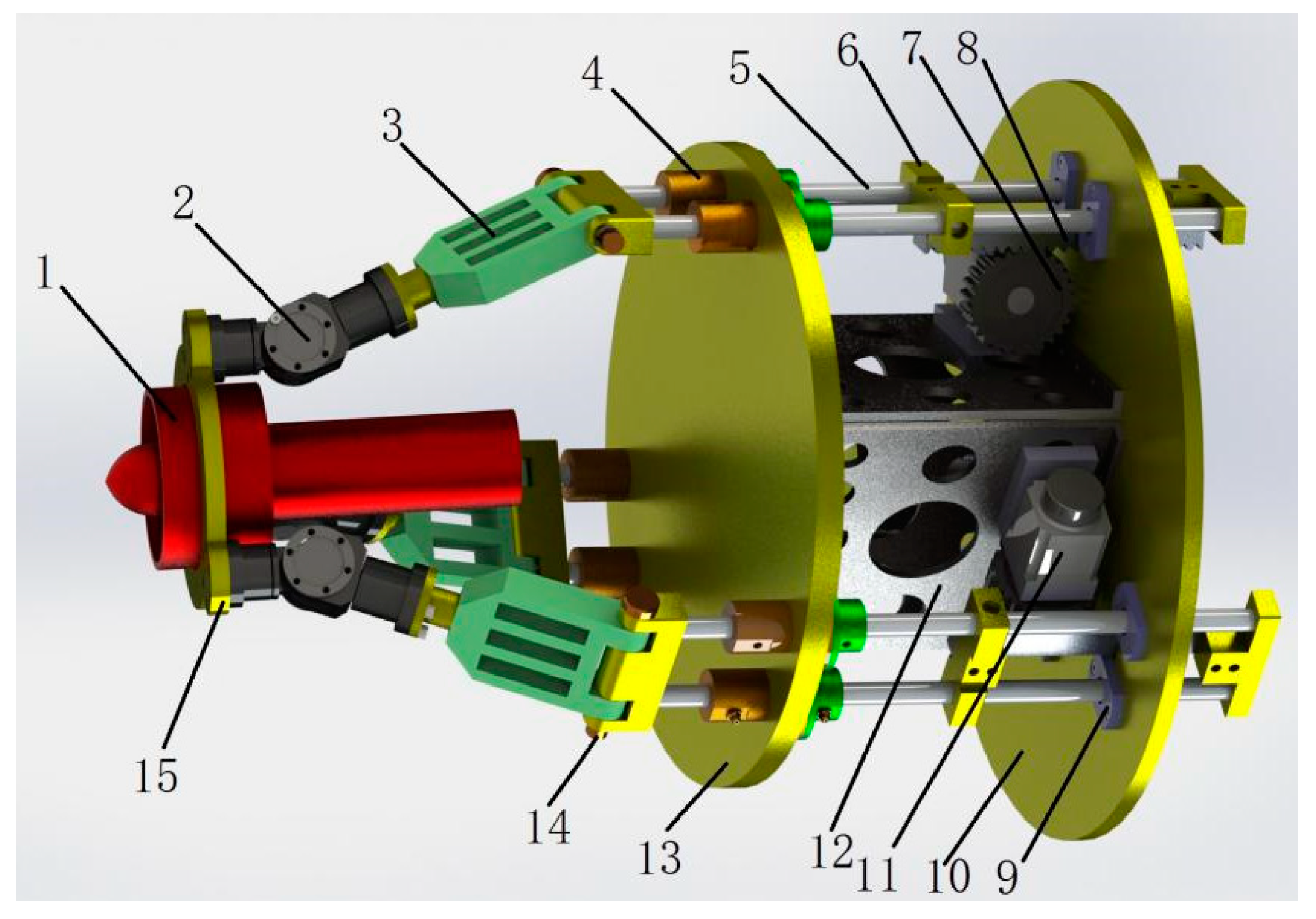
To verify the correctness of attitude control algorithm, a three-dimensional (3D) model of the 2-DOF vector propulsion system is established, shown in
Figure 4.
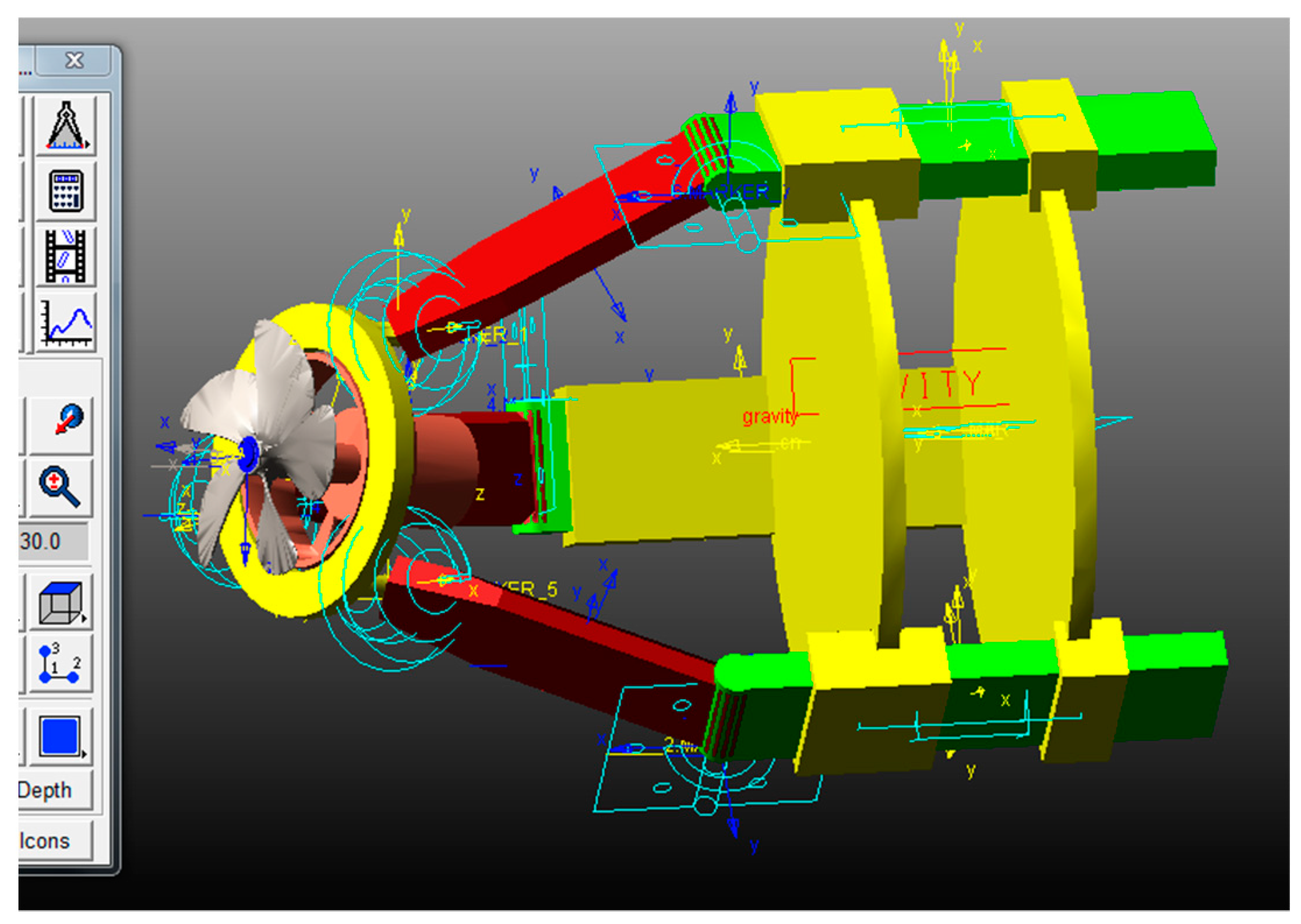
After being simplify, the model is imported into ADAMS (2019, MSC Software, Los Angeles, CA, US and 1963) motion simulation software, and motion pair constraints are added, as shown in
Figure 5.
Set structure parameters
,
, and
. The maximum nutation angle of propeller attitude can be calculated as 36.6°, so that setting
increases from 0° to 360° with step of 0.1,
increases from 0° to 36.6° with step of 0.1 when
, and remains at 36.6° when
, decreases from 36.6° to 0° with step of −0.1 when
. By means of the attitude control algorithm, the driving parameters sequences
and
could be obtained, as shown in
Table 1. From the table it is observed that the positive values of
and
indicate the displacement of the polished rods in the positive direction of the z-axis of
S coordinate, i.e., the AUV forward direction, whereas the negative values mean the displacement in the negative direction of the z-axis of
S coordinate. In
Figure 5, the positive direction of the z-axis of
S coordinate are perpendicular to the bulkhead to the right.
The driving parameters sequences are used as input parameters of ADAMS motion model to observe the propeller’s motion attitude. As shown in
Figure 6,
increases from 0° to 36.6° with slope of 1 when
, and remains at 36.6° when
, decreases from 36.6° to 0° with slope of −1 when
. Thus, the line shape stimulated by ADAMS anastomoses with the experimental figure in MATLAB (2019b, MathWorks, Natick, MA, US and 1984), which can verify the correctness of the algorithm.
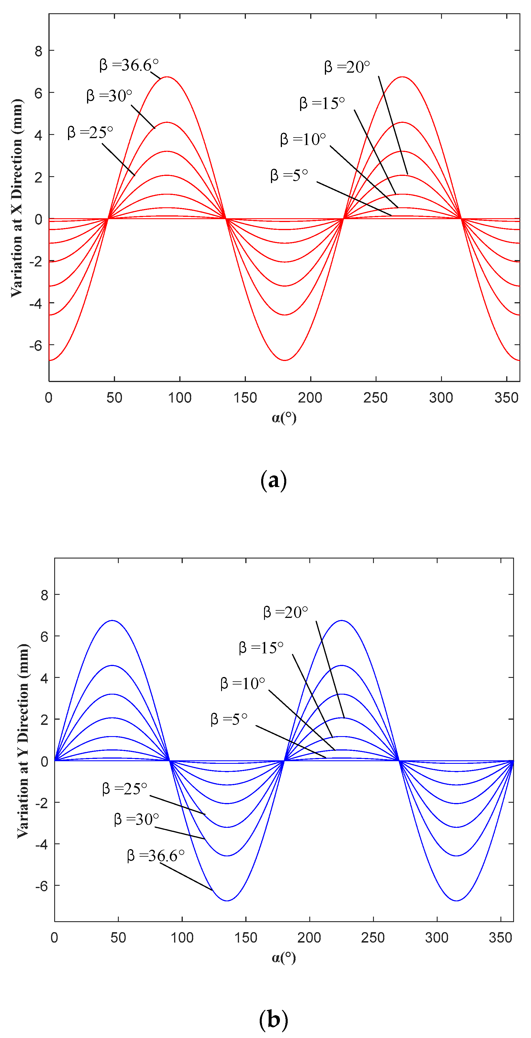
Let the nutation angle
increase from 0° to 36.6° with the step of 5°, and responding to each
,
increases from 0° to 360° with the step of 0.1°. As shown in
Figure 7a,b, it is easy to see that the variation of the M coordinate at the X and Y directions relative to the S coordinate is proportional to
and not more than 10 mm. Therefore, it can be considered that the in situ attitude adjustment is realized.
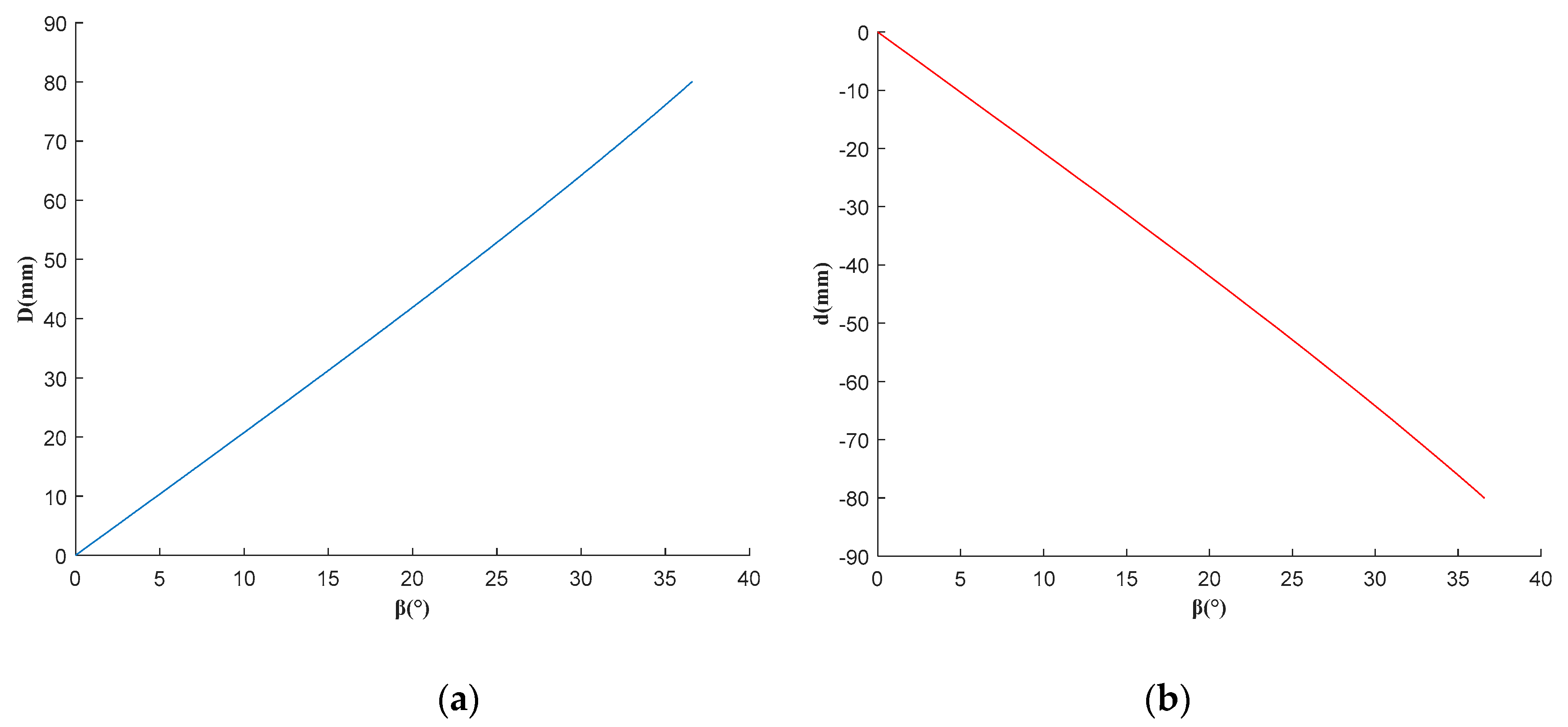
Meanwhile, the maximum and minimum values of the rod elongation during each cycle are set as
D and
d. respectively. Shown As shown in
Figure 8a,b, when
,
D reaches a maximum value of 80.063 mm, and
d reaches a minimum value of −80.063 mm. When the rod elongation of the second drive branch reaches the maximum value, the attitude is
and
. When it reaches the minimum value, the attitude is
and
.
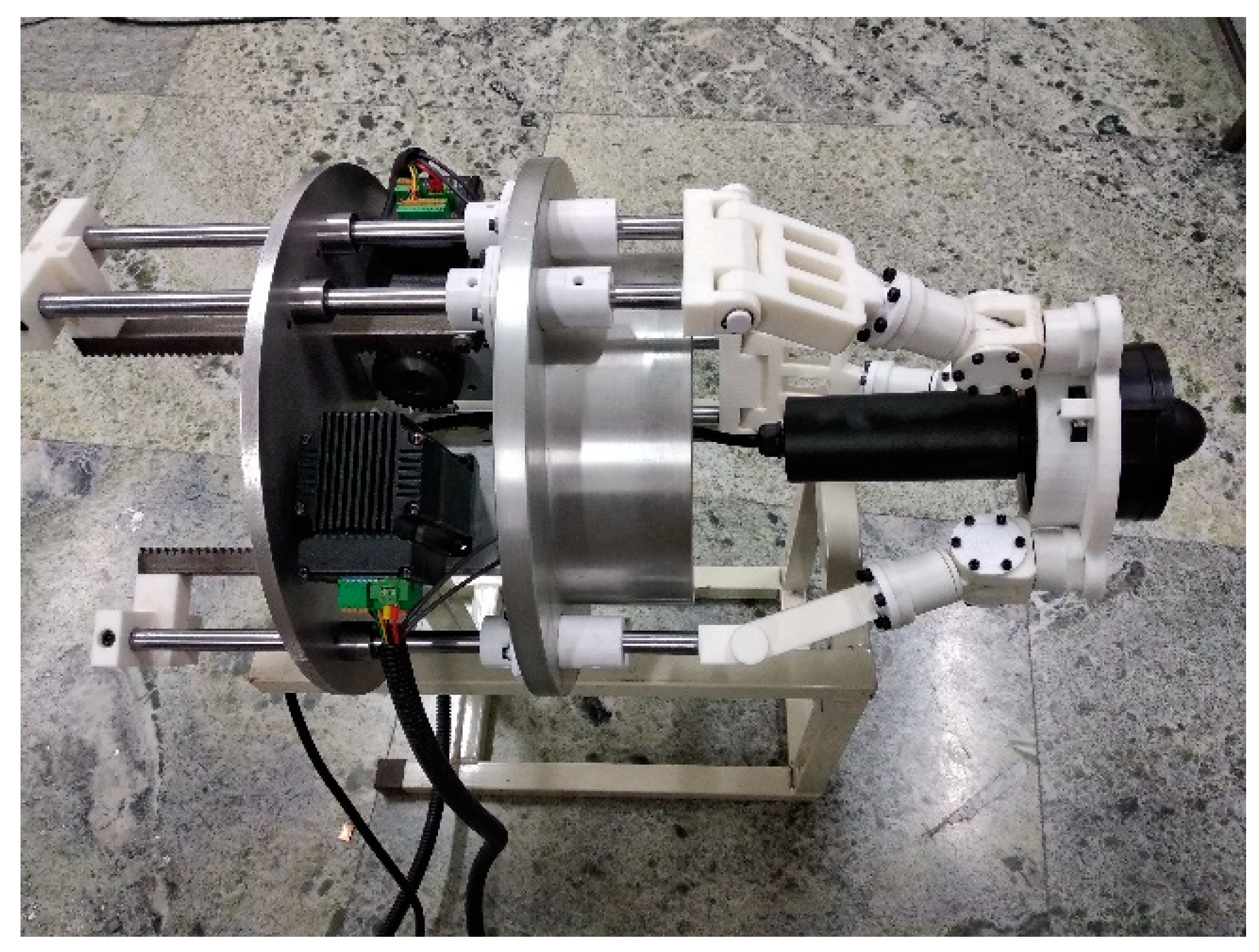
6.2. Prototype Experiment
The whole experimental platform is manufactured and assembled with the above structural parameters, shown in
Figure 9.
In order to verify that the device can meet the requirements of attitude adjustment, two attitudes,
,
and
,
, are selected for the experiment. At this time, the displacement of the polished rod of the second driving branched chain is the maximum and minimum elongation, respectively, as shown in
Figure 10a,b. Then the precession angle and the nutation angle (
,
) measured by tilt sensor are (128.8°, 36.1°) and (234.1°, 37.2°), respectively. The prototype is made by 3D printing technology, resulting in a relatively large assembly error, so it can be roughly considered that the model meets the requirements.
7. Conclusions
In order to improve the deficiency of existing vector propulsion mechanism, a 2-DOF RS+2PRS parallel vector propulsion mechanism, which has built-in actuator and simple structure. The built-in actuator makes the sealing of the propeller easier to ensure, and the propulsion device only needs two-DOF to complete the AUV attitude adjustment, avoiding the waste of power resources.
Combining with the structural characteristics of the propulsion mechanism, the ZYZ Euler angular rotation matrix is applied to solve the motion parameters coupling problem, and further an attitude control algorithm is established. The in situ adjustment of propeller attitude is realized, and therefore the required working space is small, which is beneficial to reduce the structure of AUV.
The correctness of mechanism design and control algorithm is verified by the co-simulation of MATLAB and ADAMS. Moreover, an experimental platform is built to verify the practice feasibility of the entire scheme.
Future work should include sensitivity analysis, underwater dynamics simulation, and force analysis of the propulsion mechanism on the basis of previous theoretical research and motion control, and therefore further optimize the mechanism design.
Author Contributions
Conceptualization, R.W.; methodology, R.W.; software, X.G.; validation, X.G.; formal analysis, R.W.; investigation, R.W.; resources, R.W.; data curation, X.G.; writing—original draft preparation, X.G.; writing—review and editing, R.W. and S.Z.; visualization, X.G.; supervision, S.Z.; project administration, S.Z.; funding acquisition, S.Z.
Funding
This work was supported by the National Natural Science Foundation of China (51975157) and the Natural Science Foundation of Shandong Province (ZR2017MEE062).
Conflicts of Interest
The authors declare no conflict of interest.
References
- Soriano, T.; Hien, N.V.; Tuan, K.M.; Anhb, T.V. An object-unified approach to develop controllers for autonomous underwater vehicles. Mechatronics 2016, 35, 54–70. [Google Scholar] [CrossRef]
- Dubrovin, F.S.; Scherbatyuk, A.F. Studying some algorithms for AUV navigation using a single beacon: The results of simulation and sea trails. Gyroscopy Navig. 2016, 7, 189–196. [Google Scholar] [CrossRef]
- Vega, E.P.; Chocron, O.; Benbouzid, M. AUV Propulsion Systems Modeling Analysis. Int. Rev. Model. Simul. 2014, 7, 827–837. [Google Scholar] [CrossRef]
- Liu, F.; Shen, Y.; He, B.; Wan, J.; Wang, D.; Yin, Q.; Qin, P. 3DOF Adaptive Line-Of-Sight Based Proportional Guidance Law for Path Following of AUV in the Presence of Ocean Currents. Appl. Sci. 2019, 9, 3518. [Google Scholar] [CrossRef]
- He, B.; Wang, B.R.; Yan, T.H.; Han, Y.Y. A Distributed Parallel Motion Control for the Multi-Thruster Autonomous Underwater Vehicle. Mech. Based Des. Struct. 2013, 41, 236–257. [Google Scholar] [CrossRef]
- Gao, F.; Pan, C.; Yang, Z. Nonlinear mathematics modeling and analysis of the vectored thruster autonomous underwater vehicle in 6-DOF motions. J. Eng. Mech. 2011, 47, 93–100. [Google Scholar] [CrossRef]
- Zhao, T.; Liu, M. A survey of autonomous underwater vehicle recent advances and future challenges. Fire Control Command Control 2010, 35, 1–6. [Google Scholar] [CrossRef]
- Wang, L. Water jet propulsion and jet pump. Gen. Mach. 2007, 10, 12–15. [Google Scholar] [CrossRef]
- Lin, X.; Guo, S. Development of a Spherical Underwater Robot Equipped with Multiple Vectored Water-Jet-Based Thrusters. J. Intell. Robot Syst. 2012, 67, 307–321. [Google Scholar] [CrossRef]
- Emanuele, C.; Vladimir, F.F.; Rinaldo, C.M. Path guidance and attitude control of a vectored thruster AUV. In Proceedings of the 7th Biennial Conference on Engineering Systems Design and Analysis, Manchester, UK, 19–22 July 2004. [Google Scholar] [CrossRef]
- Emanuele, C.; Rinaldo, C.M. Conceptual design of an AUV equipped with a three degrees of freedom vectored thruster. J. Intell. Robot Syst. 2010, 39, 365–391. [Google Scholar] [CrossRef]
- Chen, L.; Zhou, Z. Maneuverability Analysis of Vertical Movement of the Vectored Thruster Autonomous Underwater Vehicle. Ship Ocean Eng. 2011, 40, 119–124. [Google Scholar] [CrossRef]
- Lin, X.; Guo, S.; Yue, C.; Du, J. 3D Modelling of a Vectored Water Jet-Based Multi-Propeller Propulsion System for a Spherical Underwater Robot. Int. J. Adv. Robot. Syst. 2013, 10, 80–88. [Google Scholar] [CrossRef]
- Liu, T.; Hu, Y.; Xu, H.; Zhang, Z.; Li, H. Investigation of the vectored thruster AUVs based on 3SPS-S parallel manipulator. Appl. Ocean Res. 2019, 85, 151–161. [Google Scholar] [CrossRef]
- Ba, X.; Luo, X.; Shi, Z.; Zhu, Y. A vectored water jet propulsion method for autonomous underwater vehicles. Ocean Eng. 2013, 74, 133–140. [Google Scholar] [CrossRef]
- Qu, H.; Liang, Y.; Fang, Y. Statics and stiffness analysis of 4-RRS redundant spherical parallel mechanism. J. Eng. Mech. 2015, 11, 8–15. [Google Scholar] [CrossRef]
Figure 1.
2-DOF (degree-of-freedom) parallel vector propulsion mechanism.
Figure 1.
2-DOF (degree-of-freedom) parallel vector propulsion mechanism.
Figure 2.
Driving chain .
Figure 2.
Driving chain .
Figure 3.
(a) The attitude when the fixed driving branch chain is parallel to the motor spindle and (b) the attitude when the movable driving branch chain is parallel to the motor spindle.
Figure 3.
(a) The attitude when the fixed driving branch chain is parallel to the motor spindle and (b) the attitude when the movable driving branch chain is parallel to the motor spindle.
Figure 4.
3D model of 2-DOF propulsion mechanism. 1, propeller; 2, spherical hinges; 3, fixed-length bars; 4, sealing device; 5, polished rod; 6, rack installing seat; 7, gear; 8, rack; 9, linear guide with flange; 10, front bulkhead; 11, motor; 12, reinforcing plate; 13, rear bulkhead; 14, revolute joint; and 15, the propeller installation platform.
Figure 5.
Simulation model of 2-DOF propulsion mechanism.
Figure 5.
Simulation model of 2-DOF propulsion mechanism.
Figure 6.
The line of nutation angle following precession angle changes.
Figure 6.
The line of nutation angle following precession angle changes.
Figure 7.
(a) The line of the variation at the X directions following and changes and (b) The line of the variation at the Y directions following and changes.
Figure 7.
(a) The line of the variation at the X directions following and changes and (b) The line of the variation at the Y directions following and changes.
Figure 8.
(a) The line of D following changes and (b) The line of d following changes.
Figure 8.
(a) The line of D following changes and (b) The line of d following changes.
Figure 9.
Experimental platform for 2−DOF propulsion mechanism.
Figure 9.
Experimental platform for 2−DOF propulsion mechanism.
Figure 10.
(a) The model attitude when , and (b) The model attitude when , .
Figure 10.
(a) The model attitude when , and (b) The model attitude when , .
Table 1.
Driving parameters , for different attitude angles.
Table 1.
Driving parameters , for different attitude angles.
| | | | |
|---|
| 0 | 0 | 0 | 0 | 0 |
| 1 | 10 | 10 | −17.0477 | −20.1788 |
| 2 | 20 | 20 | −31.2626 | −41.7985 |
| 3 | 30 | 30 | −39.9409 | −59.2448 |
| 4 | 40 | 36.6 | −35.2916 | −62.2278 |
| 5 | 50 | 36.6 | −18.0474 | −52.8458 |
| 6 | 60 | 36.6 | 0 | −43.4968 |
| 7 | 70 | 36.6 | 18.0474 | −34.7984 |
| 8 | 80 | 36.6 | 35.2916 | −26.9362 |
| 9 | 90 | 36.6 | 50.8755 | −19.7709 |
| … | … | … | … | … |
| 17 | 170 | 36.6 | 52.8458 | 34.7984 |
| 18 | 180 | 36.6 | 43.4968 | 43.4968 |
| 19 | 190 | 36.6 | 37.7984 | 52.5458 |
| … | … | … | … | … |
| 29 | 290 | 36.6 | −34.7984 | 18.0474 |
| 30 | 300 | 36.6 | −43.4968 | 0 |
| 31 | 310 | 36.6 | −52.8458 | −18.0474 |
| 32 | 320 | 36.6 | −62.2278 | −35.2916 |
| 33 | 330 | 30 | −59.2448 | −39.9409 |
| 34 | 340 | 20 | −41.7985 | −31.2626 |
| 35 | 350 | 10 | −20.1788 | −17.0477 |
| 36 | 360 | 0 | 0 | 0 |
© 2019 by the authors. Licensee MDPI, Basel, Switzerland. This article is an open access article distributed under the terms and conditions of the Creative Commons Attribution (CC BY) license (http://creativecommons.org/licenses/by/4.0/).


