Review

Plasmonic Tweezers towards Biomolecular and Biomedical Applications

School of Optoelectronic Engineering and Instrumentation Science, Dalian University of Technology, Dalian 116024, China
*
Author to whom correspondence should be addressed.
Appl. Sci. 2019, 9(17), 3596; https://doi.org/10.3390/app9173596
Submission received: 30 June 2019 / Revised: 21 August 2019 / Accepted: 29 August 2019 / Published: 2 September 2019
(This article belongs to the Special Issue Optical Trapping)

Abstract

:
With the capability of confining light into subwavelength scale, plasmonic tweezers have been used to trap and manipulate nanoscale particles. It has huge potential to be utilized in biomolecular research and practical biomedical applications. In this short review, plasmonic tweezers based on nano-aperture designs are discussed. A few challenges should be overcome for these plasmonic tweezers to reach a similar level of significance as the conventional optical tweezers.

1. Introduction

In 1970, Ashkin published two letters in Physical Review Letters to demonstrate the radiation pressure from laser beams exerted on particles [1] and atoms [2]. In 1986, he developed the seminal single beam gradient force optical tweezers (OTs) [3], and he successfully trapped viruses, bacteria and single cells with this technique in 1987 [4,5]. Inspired by his pioneering work, researchers have utilized OTs to study mechanical properties of biological particles and systems [6,7,8], e.g., torsional compliance of flagella in tethered Escherichia coli and motile Streptococcus [9], tensions of DNA molecules [10,11], motions of motor protein myosin-I and kinesin [12,13], discrete step motion of RNA polymerase in transcription processes [14], and topological organization of a T4 lysozyme protein [15]. OTs have also been applied in vivo, e.g., manipulating red blood cells in subdermal capillaries of a living mouse for a potential blockage clearance [16] and manipulating the ear bone of a laver zebrafish [17]. Due to the profound importance of OTs in biological and medical applications, Ashkin won one half of the Nobel Physics Prize in 2018.
OTs can apply pico-Newton scale forces to bioparticles in the range of hundreds of nanometers to a few microns. However, to trap Rayleigh bioparticles well below the diffraction limit (<100 nm), directly using conventional OTs is difficult. First, since the size of the particle is much smaller than the focused laser beam, the amount of light can be used for trapping is limited by the volume of the nanoparticle. Second, the difference between the refractive index of the bioparticle and the aqueous environment is extremely small, which reduces the polarizability of the particle and consequently the optical force. Third, when the size of the particle is reduced, the viscous drag is decreased, which is not favorable. It is extremely important to have stable, non-invasive and flexible techniques to trap and manipulate nanoscale bio-samples in the intracellular environments [18], so alternative photonic methodologies that could generate nanoscale near fields have been developed [19]. Using evanescent fields, micron and sub-micron particles have been trapped and transported for sorting purposes [20,21,22,23]. Due to the field gradient of the evanescent field only pulling the particle to the surface of the waveguide but pushing the particle along the light propagation direction, 3D nanostructures, e.g., photonic crystals (PCs) cavities [24] and silicon nano-antennas [25], have been designed to tailor the near fields for 3D light confinements.
Besides nanophotonic techniques based on dielectric materials, plasmonic tweezers (PTs) based on surface plasmon polaritons (SPPs) generated at the interface of a dielectric medium and a conductive material is another major branch of nanoparticles manipulating methodologies. Optical force generated by surface plasmon resonance (SPR) was first proposed by Song and his colleagues in 2001 [26]. In 2004, Kwak et al. demonstrated trapping 200 nm fluorescent latex particles using the intense near field gradients generated around holes in gold thin films [27]. In 2008, PTs based on pairs of gold nanodots was demonstrated by Grigorenko et al. [28]. With the development of the fabrication technologies, simulation methodologies and materials science, PTs have been developed quickly in the last 10 years, which leads to improved trapping performance [29,30] and applications in biological research [31].
In this short review, PTs engineered toward biomolecular and biomedical applications are discussed. In Section 2, optical trapping using self-induced back-action effect and chiral optical forces of the enhanced near chiral fields are discussed. In Section 3, PTs based on a few different nano-aperture designs are covered. In Section 4, an outlook containing future trends in PTs and challenges needs to be conquered to achieve meaningful applications in biomolecular and biomedical areas is provided. Trapping based on isolated nanostructures is not covered here. They have also shown strong traps for nanosize particles [32] and biological samples [33,34,35]. Due to the possible heat accumulation [36,37], they are not favorable to bioparticles trapping and manipulation due to enhanced Brownian motion and bubble formation. PTs based on nano-aperture designs can avoid heat accumulation. Because of the high thermal conductivity, locally generated heat can be dissipated quickly through the metal layer to avoid thermal damage to the trapped bioparticles. Another advantage of using nano-aperture designs is that electrical potential modulation can be applied, and other manipulation and sensing techniques can be combined with these PTs.

2. Optical Forces

The generation of optical force for OTs and PTs is the same, transferring momentum from a photon to a particle. To have a trap, a strong field gradient is needed. Compared to the wavelength ( λ ) of the trapping laser, particles are divided into Mie particles ( d λ , ray optics), Lorentz–Mie particles ( d ~ λ , Maxwell stress tensor), and Rayleigh particles ( d λ , dipole approximation) for OTs, where d is the diameter of the particle [38,39,40]. Optical force applied on Rayleigh particles are discussed for OTs and PTs.
Due to the fact that a Rayleigh particle is much smaller than the diffraction limited focused laser beam for OTs, the particle can be treated as a dipole or a collection of dipoles. Take a spherical particle as an example. The polarizability of the particle can be expressed as in Equation (1), where k is the field wavevector, α 0 is the point-like particle polarizability from Clausius–Mossotti relation [41], ε 0 , ε and ε b is the vacuum dielectric permittivity, and relative permittivity of the particle and the background medium, respectively. As we can observe that the polarizability of the particle is proportional to the cubic of the diameter of the particle and the difference between the relative permittivity of the particle and the one of the surrounding medium:
α ( ω ) = α 0 ( ω ) 1 i k 3 α 0 ( ω ) 6 π ε 0 , α 0 ( ω ) = 4 π ε 0 ( d 2 ) 3 ε ( ω ) ε b ( ω ) ε ( ω ) + 2 ε b ( ω ) .
Based on the dipole approximation, the time averaged force applied on the particle from the light field is shown in Equation (2), where σ is the extinction cross-section [42]:
F = 1 4 Re ( α ) | E | 2 + σ 2 c Re ( E × H * ) + σ c ε 0 4 ω i × E × E * .
The angular brackets denote time average. The first term in Equation (2) is from the intensity gradient which pulls the particle to the highest intensity location. For a particle having a larger polarizability, the gradient force is larger when the same incident intensity is used. The second term corresponds to the radiation pressure which pushes the particle along the light propagation direction. The third term is from the polarization gradient, which corresponds to the chiral optical force that is discussed in Section 2.2. As we can observe from this equation, the intensity gradient force is proportional to the polarizability of the particle and intensity of the field. When the size of the particle is reduced 10 times, 1000 times higher intensity is needed to maintain the trap at the same potential depth. To compare the trap stiffness among different OTs and PTs, the radius and dielectric constant of the particle should also be factored out when the same incident intensity is used.
Since the nanoscale enhanced near fields generated by PTs having similar size as the nanoparticles, dipole approximation is not viable. Maxwell stress tensor (MST) T is used to obtain the optical force applied on the nanoscale particle from this arbitrary electromagnetic field as shown in Equation (3) [43]. The integral is taken over a surface S enclosing the particle, and n ( r ) is the outward unit vector normal to the integration surface. Besides a few cases that involve simple plasmonic designs [44], it is extremely difficult to have analytical results of optical forces. To obtain as large field gradients as possible, most designs of PTs contain very complicated and irregular 3D geometries. Numerical simulation is mainly used to obtain the near field distribution. Finite element method (FEM) [45,46] and finite-difference time-domain (FDTD) [47] method are the most used simulation strategies:
F = S T ( r , t ) n ( r ) d a .
In this section, self-induced back-action (SIBA) effect and chiral optical forces are discussed as the extensions of PTs using linear momentum transfer.

2.1. Self-Induced Back-Action Effect

Although the enhanced near field can be used to provide nanoscale gradient field for nanoparticle trapping and nano-aperture designs can avoid the heat accumulation, other possible damage e.g., photo damage still presents. A novel trapping mechanism is needed to provide similar level of trap stiffness at an extremely low intensity. The self-induced back-action (SIBA) effect is a trapping mechanism utilizing the trapped particle as an active role to modify its own trapping potential dynamically. The presence of the particle shifts the resonance frequency of the trapping system and this shift is dynamically decided by the position of the nanoparticle in the plasmonic cavity. Compared to the trapping mechanism based on the field gradient (static trapping), trapping using a SIBA effect is dynamic and an off-resonance frequency is used. SIBA based on planar PC cavities was theoretically proposed by Barth and Benson in 2006 [48]. In 2009, the SIBA phenomenon was demonstrated by using a nanohole in a metal thin film on trapping single 50 nm polystyrene particles with 1.9 mW incident power [49]. In 2013, experimentally using PCs to trap 500 nm dielectric particles with SIBA effect was achieved by Descharmes et al. using a waveguide power lower than 0.12 mW [50].
The presence of the particle at position r in a plasmonic adiabatic cavity causes a shift in the resonance frequency, δ ω ( r ) = ω c ( r ) ω c , 0 and the intra-cavity intensity profile I ( r ) is expressed as Equation (4), where ω is the frequency of the trapping laser, Γ is the empty cavity linewidth, ω c , 0 is the resonance frequency of the empty cavity, Δ ω ω c , 0 is the cavity detuning, I o p t I 0 ( Γ 2 ) 2 Δ 2 + ( Γ 2 ) 2 is the empty cavity profile when there is no particle presence in the cavity, I 0 is the incident intensity, and a Taylor expansion is used to expand the modified cavity profile [51]. When the particle cannot shift the resonance frequency large enough, Equation (4) reduced to I o p t , since the particle influence on the system is negligible. Then, we discuss the cases when the particle can introduce significant resonance frequency shift to the plasmonic cavity:
I ( r ) = I 0 ( Γ 2 ) 2 ( Δ δ ω ( r ) ) 2 + ( Γ 2 ) 2 I o p t 2 δ ω ( r ) Δ Δ 2 + ( Γ 2 ) 2 I o p t + .
Since the trap stiffness is proportional to the intensity of the intra-cavity intensity, the total trap stiffness, k t o t , can be expressed as in Equation (5) when only the first two terms in Equation (4) are considered when δ ω ( r ) is much smaller than ω c , 0 :
k t o t = k o p t + k S I B A ,
where k o p t depends on the empty cavity resonance profile and k S I B A originates from the coupling between the motion of the particle and the resonance of the plasmonic cavity. Since a bioparticle always have a slightly higher refractive index compared to an aqueous surrounding, δ ω is always positive. To make the second term positive, Δ needs to be negative. A red cavity detuning ( ω < ω c , 0 ) should be selected to generate a positive SIBA effect. Examine the expression of k S I B A in Equation (4), when Δ = δ ω ( r m a x ) is satisfied the value of k S I B A is maximized and this position is defined as resonant position of the particle. The definition of the back-action parameter is shown in Equation (6), where V m is the mode volume and Q is the quality factor of the empty cavity [52]. This parameter is predefined by the properties of the particle and the plasmonic cavity. This parameter also can be understood as the capability of the particle in shifting the resonance frequency of the plasmonic cavity. In a different position, the particle will generate different values of δ ω ( r ) as in Equation (7), where 0 f ( r ) 1 is a normalized spatial intensity profile of the empty cavity and it follows the resonance symmetry of the plasmonic cavity. To have a large ν parameter, the plasmonic cavity should be designed with a large Q and a small V m . For a fixed working environment (i.e., background medium, nanoparticle and plasmonic cavity), a proper value of detuning Δ should be selected:
ν α ( ω ) ε 0 V m Q = α ( ω ) ε 0 V m ω c , 0 Γ ,
2 δ ω ( r ) Γ = ν · f ( r ) .
To understand the SIBA effect, the number of photons in the cavity can be examined to demonstrate the change in the momentum that transferred to the particle from the photons. In Equation (8), p is the momentum of the particle, is the reduced Planck constant, and n ( r ) is the number of photons in the cavity that is decided by the position of the particle and can be expressed in Equation (9), where Γ e x denotes the source of the injection of photons into the cavity at an incident intensity I 0 at laser frequency ω and the decay rate of the cavity into specific external channels. When the particle is located at the resonant position and Δ = δ ω ( r m a x ) is satisfied, then the number of photons in the cavity is also locally maximized. In addition, the strongest gradient force is generated to trap this particle. When the particle is getting closer to a resonant position, a deeper potential will be generated to suppress the Brownian motion of the particle. Compared to a trap (static type) working at the resonance condition, the time averaged intensity experienced by the trapped particle is much lower since, most of the time, the system is not at resonance due to the detuning. This dynamic trapping mechanism protects the trapped particle from possible photo damage:
d p d t = n ( r ) δ ω ( r ) ,
n ( r ) = 4 I 0 Γ e x Γ 2 1 1 + ( ν · f ( r ) + 2 Δ Γ ) 2 .
Polystyrene particles with 22 nm diameter have been successfully trapped with SIBA effect at 2.5 mW [53]. For smaller biomolecules, e.g., proteins in a few nanometers, advanced designs of plasmonic cavities are needed to provide a large quality factor and a small mode volume to boost the back-action parameter. This novel trapping mechanism is quite important. A slightly red-detuned laser beam with an extremely low incident power can provide deep potential dynamically to trap and manipulate nanosize bioparticles without thermal nor photonic damage.

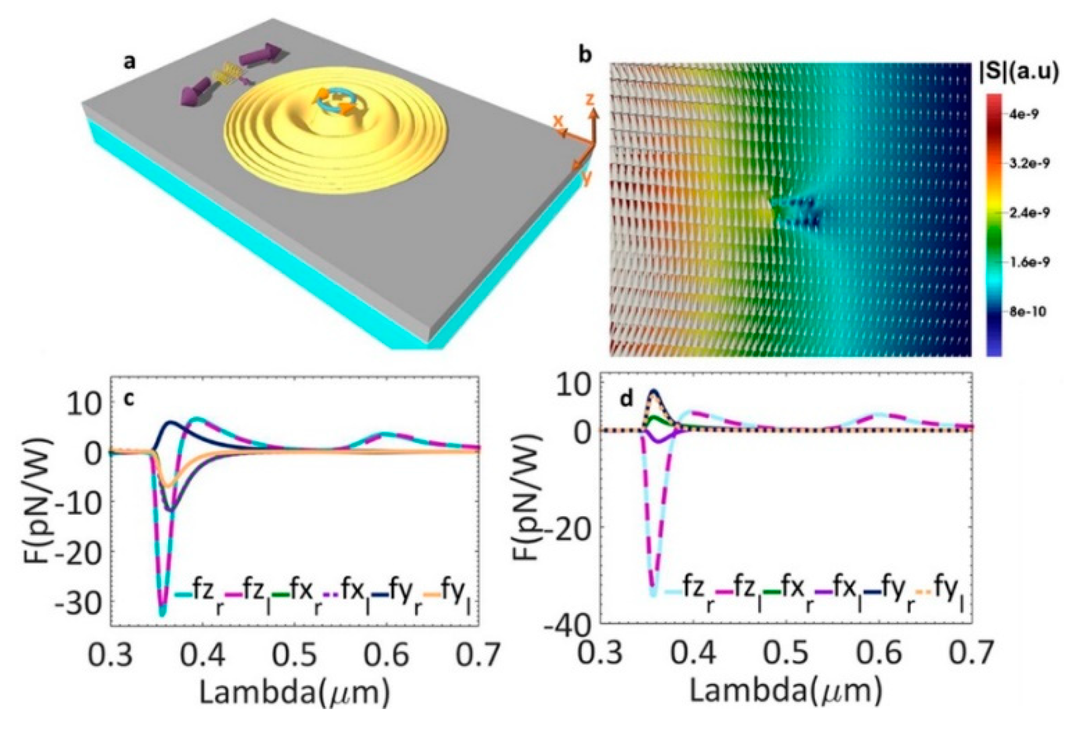
2.2. Chiral Optical Force

Angular momentum also can be transferred to a non-chiral particle to make it spin or rotate. More important for chiral particles, a right-handed one and a left-handed one experience chiral optical forces in the opposite directions. This phenomenon is important to separate particles with different chiralities. For example, a protein could become toxic to a cell if it loses its original chirality and this process has been suggested as one of the underlying causes of Alzheimer’s, Parkinson’s and type II diabetes [54]. Besides sensing the chirality of these proteins, to separate the misfunction proteins at each stage of a disease could be meaningful to design specific drugs to target these proteins at different stages. In addition, for enantiopure drugs that target specific cellular receptors, the correct chirality is a guarantee to provide effective therapy at the molecular level. This separation mechanism could be used as quality control methodology.
A chiral particle can be modelled as a pair of interacting electric and magnetic dipoles, and this interaction can be expressed with a polarizability α e m , as shown in Equation (10), where κ is the chirality of the particle, μ and μ b is the relative permeability of the particle and background medium, respectively. Then, the third term in Equation (2) can be modified to Equation (11) for transverse optical force of the chiral optical force. Here, the curl-spin force and vortex force are negligible for nanoscale bioparticles when the trapping laser frequency is selected in the visible and near infrared regimes, which is most of the circumstances to avoid the background medium absorption. Since κ could be positive or negative, this chiral gradient force could be addition or subtraction to the intensity gradient force, and particles with difference chirality can be separated [55]:
α e m = 12 π ( d 2 ) 3 i κ μ 0 ε 0 ( ε + 2 ε b ) ( μ + 2 μ b ) κ 2 ,
F t r , c h = 1 2 Im ( α e m ) Im ( E · H * ) .
Alizadeh and Reinhard theoretically proposed using chiral SPPs based on metal thin films to generate transverse spin angular momentum (SAM) for right- and left-handed molecule separation [56]. The proposed chiral molecule separation scheme is as follows. A left-handed circularly polarized dipole was used as the source. Figure 1a demonstrates the generated chiral transverse forces on two different chiral helix tubes. They have a radius of 2.5 nm, a period of 7.5 nm, five loops and different handedness. They were put 500 nm away from the near field chiral source along x-axis and 10 nm above the metal surface along the z-axis. In Figure 1b, the distribution of SAM in the x-y plane is demonstrated with the amplitude as the background. In Figure 1c, the forces applied on these tubes when they were on the positive x-axis are plotted. Forces along the y-axis have opposite signs for right- and left-handed helix tubes. When particles were on the positive y-axis, opposite forces along the x-axis for two helices are observed in Figure 1d.
Using these chiral optical forces, it is possible to integrate sorting channels to separate bio-and medical molecules with different chirality. Other designs were also proposed for the particle separation function using chiral optical forces [57,58]. Currently, experimental work has not been successfully conducted to our knowledge, while plasmonic designs have already been applied in sensing the chirality of proteins [59].

3. Major Designs

A few major designs of PTs and examples of experimental works are covered in this section. To compare the trapping performance, the scaled trap stiffness at 1 mW / μ m 2 incident intensity is usually used. Size dependent factor is ( × 20 nm/d)3 and refractive index factor is Clausius–Mossotti relation with polystyrene material as the reference [60].

3.1. Single Nanoholes

Single nanoholes were applied in DNA trapping by Kim and Lee in 2014 [61]. Both 4.7 kbp plasmid DNAs and 48 kbp DNAs were trapped by 400 nm diameter holes in 100 nm thick gold films. The extraordinary transmission (EOT) phenomenon was used to generate near fields for PTs. The transmission intensity from a 1050 nm trapping laser was monitored. In Figure 2a,b, transmission intensities while trapping plasmid DNAs at 7.8 mW and 13.2 mW are shown. For lambda DNAs, transmission intensities are demonstrated in Figure 2c,d at the same two powers. For both DNAs, the trapping duration was shorter at 7.8 mW. At the same trapping power, the larger lambda DNA introduced a bigger transmission intensity increase.
This work demonstrates the potential of PTs in distinguishing DNAs with different lengths by monitoring the transmission signal. Since the light confinement from a nanohole structure is not as strong as sharp tips contained nanostructures, nanoholes are not good candidates to trap nanoscale bioparticles.

3.2. Bowtie Nano-Apertures (BNA)

Bowtie nanostructure is the most used plasmonic design in sensing and trapping with localized surface plasmons (LSP), since they can provide strong light confinements between the two sharp tips. They have been used to trap and manipulate nanoscale particles [62,63,64], but the heating accumulation could be an issue for stable trappings and the bio-sample integrity [65].
Similar to the protruding bowtie nanostructures, bowtie nano-apertures (BNAs) also can be used to generate strong confinements which provide large near field gradients for optical trapping. Similar to monitoring transmission to detect trapping events, the second harmonic (SH) signal from the PTs was used to identify successful trappings by S. J. Yoon et al. [66]. The presence of the trapped nanoparticle enhances the field distribution near the tips and thus the SH signal is enhanced. The SH signal is quadratic dependent on the intensity and an optical filter which blocks the transmitted laser beam can be used to collect the SH signal. This methodology is more sensitive than the transmission measurement. The scheme of nanoparticle trapping and SH signal for monitoring purposes is shown in Figure 3a. The BNA was designed in a 100 nm thick gold film deposited on a SiO2 substrate. Two apexes were tailored in 3D. The plasmonic resonance ( λ ω ) of this system in water was 1560 nm. A CW (continuous wave) laser at 1560 nm was used as the trapping light source and a femtosecond pulsed laser at 1560 nm was used as the SH pump source. The simulated near field distribution is shown in Figure 3b. The maximum enhancement is perpendicular to the surface of the gold thin film and the SH signal ( λ 2 ω = 780   nm ) can be generated from the gold surface where the inversion symmetry is broken. In Figure 3c, SEM images of a fabricated BNA are demonstrated. CdSe/ZnS (diameter ~4.0 nm, λ e m ~620 nm, not excited) quantum dots were successfully trapped. Figure 3d,e are the plots of SH signal intensity with fixed pump power at 4 mW when two trapping powers at 10 mW and 40 mW were used. Figure 3f,g are the corresponding transmission intensity plots. As expected, the presence of the quantum dot affected the distribution of the near field, and the SH signal and transmission signal were both modified. Three gaps of 5 nm, 8 nm, and 10 nm were tested. For 5 nm gap size BNA, the largest change in SH and transmission signal was observed. Spikes in both signals demonstrate that the quantum dot oscillated in the gap region.
BNAs have also been applied in trapping 20 nm polystyrene particles with a SIBA effect [67] and quantum dots [68]. Although the transmission and SH signal from PTs can be monitored to identify trapping events for nonfluorescent particles, this type of detection methodology is not good enough since no comprehensive information of the trapped particle can be provided. Utilizing the enhanced near field, specific light-matter interactions, e.g., Raman scattering, can be applied to identify the trapped particle when a long, stable trapping can be achieved. Although the SH signal from PTs, not the trapped particle, was utilized, their research expands the monitoring methods for nanoscale particles trapping.

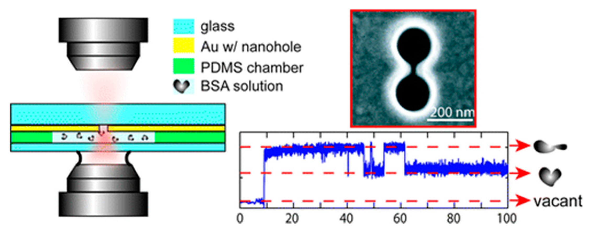
3.3. Double Nanoholes

Double nanoholes are the most used nanostructures for PTs [69]. Using a double nanohole with 15 nm gap, Reuven Gordon’s group have trapped single BSA protein (~3.4 nm) between the two tips in 2012 [70]. They also observed the unfolding process of a trapped protein by changing the PH value of the solution and changing the laser power. Besides the BSA protein, they have trapped and manipulated DNAs [71] and single egg white protein [72], and examined biotin−streptavidin, biotin−monovalent streptavidin, and acetylsalicylic acid−cyclooxygenase 2 interactions [73]. As shown in Figure 4, an experimental trapping scheme is demonstrated on the left side. On the right side, the top figure is an SEM image of a double nanohole and the bottom figure is the transmission signal. With a protein trapped, the transmission signal was increased due to the locally increased refractive index introduced by the presence of the protein. Two states of the protein were observed since the unfolded protein occupied more volume between the two tips. Using the transient time ( τ ) of the upward steps in the transmission signal, the trap stiffness of these PTs can be calculated using Equation (12) [60]:
τ = γ k ,
where k is the trap stiffness and γ is the Stokes drag coefficient. Modified double nanohole design–arrays of nanoholes connected along one direction were used in trapping multiple 30 nm polystyrene particles and sequence trapping events were observed with multiple upward steps in the transmission signal [45].

3.4. Annular Apertures

To achieve an even tighter light confinement, the atomic layer lithography methodology was invented to fabricate sub-10 nm gaps in 2013 [74]. The simulation work of sub-10 nm coaxial plasmonic aperture on trapping sub-2 nm particles was conducted by Saleh and Dionne in 2012 [75]. In 2018, Yoo et al. achieved 10 nm annular apertures and trapped streptavidin molecules (molecule size ∼4.5 nm × 4.5 nm × 5.8 nm) with 4.5 mW incident power [76]. As shown in Figure 5a,b, the simulated thermal accumulation is plotted for a standing along bowtie structure and a coaxial aperture. It is evident that an aperture design does not have strong heat accumulation due to the heat dissipation through the metal thin film. An optical image of the fabricated 10 nm gap coaxial aperture array is demonstrated in Figure 5c. The inset is an SEM image of an annular aperture. The trapping scheme is demonstrated in Figure 5d. Transmission detection technique was used to monitor the trapping events. As mentioned in Section 2.2 of chiral optical force, this design can be used to separate chiral molecules.
In Table 1, trap stiffness based on different nanotweezers are listed to roughly compare their experimental performance on nanoscale particle trapping. Tweezers based on PCs and plasmonics are both listed to demonstrate their developments and to compare their trapping performance. For a particle with 20 nm diameter, current PTs can experimentally provide trap stiffness around 0.1 fN/nm with 1 mW / μ m 2 incident intensity. Although nanoparticles in a few nanometer diameters can be experimentally trapped, repeatability still needs to be improved. An extremely stable trapping environment is mandatory to trap nanosize bioparticles.

4. Outlook

Using PTs to trap nanoscale particles, enhanced sensing is provided naturally by the nanoscale enhanced near fields [80]. Nanometric PTs based on nano-aperture designs also provide simplicity to be integrated on a chip that could contain sources, modulators and detectors. Compared to nanotweezers based on dielectric materials, PTs based on conductive materials have another attractive feature, i.e., electrical conductivity. PTs can be combined with other long-range trapping techniques and the resonance can be tuned electrically. PTs have huge potential to be integrated on lab-on-a-chips as miniaturized instrumentations used in bio- and medical molecules research and practical applications.

4.1. Multifunctional PTs

Since PTs are based on conductive materials, electrophoresis (EP) [81] and dielectrophoresis (DEP) [82,83,84,85,86] can be applied to transport particles from the far field to the optical near field to feed PTs [87,88]. Using this combination, no extremely long waiting time is needed when extremely low concentration solutions are used. Another advantage of this combination is that comprehensive information can be detected for the particle [89]. Usually, when a dielectric particle is trapped in the aperture, the electrical current is decreased, and this difference can be used to characterize the size of the particle.
It is also intriguing to use 2D materials for PTs. Graphene is considered as a good plasmonic materials with an extremely high intrinsic electron mobility [90,91], high transparency in a broad spectrum [92,93], and high thermal conductivity [94]. A nanohole in graphene was proposed for PTs and compared to the same design based on gold thin films [95]. To our knowledge, there is currently no experimental work on nanoscale bioparticle trapping using graphene based PTs.
Dynamically tuning the plasmonic resonance is another important characteristic for the future PTs. The carrier density of the graphene that decides the resonance frequency can be externally controlled by a gate voltage [96,97]. Dynamically tuning the resonance frequency alters the local field enhancement and the force applied on the particle [95]. With this feature, particles can be trapped and released by slightly tuned the gate voltage theoretically.

4.2. Challenges

There are still challenges for PTs to conquer to achieve a similar level of significance as the conventional OTs.
Multiple trapping sites can be achieved and the distances among them can be modified dynamically through various optical methodologies for OTs [98,99]. Using this feature, interactions between the trapped micron biological particles have been examined and the micron robot has been assembled [100,101]. Unlike conventional OTs, the distance among different trapping sites is fixed for PTs after the fabrication process. A possible solution is using chiral optical force. With the combination of rotation and linear motions, it might be possible for a nanoscale robot to be assembled. To directly stretch a DNA or unfold a protein to explore their intrinsic properties in their natural environments is not possible based on current PTs designs. Studying bioparticles without using handles nor labels is important, and using PTs is the most possible strategy to achieve this ultimate goal.
Another challenge stays in the force calibration for the nanoscale, irregular shape bioparticles. For most of the simulation work, the bioparticles are treated as spheres and biomolecules are treated as dipoles. This is not good enough to provide guidance for the experimental work. In addition, most of the experimental work demonstrated successful trapping events without trap stiffness determined. Currently, PTs are mainly used to demonstrate that it can be used as tweezers to trap nanoscale particles. However, the force characterization ability has not been developed to understand the mechanical properties of the biomolecules and bio-reactions.

5. Conclusions

With further developments in the fabrication and simulation, these challenges could be solved, and PTs integrated with other techniques, e.g., microfluidics and EP/DEP, would play an important role in the future biomolecular research and medical applications.

Author Contributions

The authors contributed equally.

Funding

This paper was supported by the Fundamental Research Funds for the Central Universities (DUT18RC(3)065).

Acknowledgments

The authors would like to thank the School of Optoelectronic Engineering and Instrumentation Science at Dalian University of Technology.

Conflicts of Interest

The authors declare no conflict of interest.

References

  1. Ashkin, A. Acceleration and Trapping of Particles by Radiation Pressure. Phys. Rev. Lett. 1970, 24, 156–159. [Google Scholar] [CrossRef] [Green Version]
  2. Ashkin, A. Atomic-Beam Deflection by Resonance-Radiation Pressure. Phys. Rev. Lett. 1970, 25, 1321–1324. [Google Scholar] [CrossRef]
  3. Ashkin, A.; Dziedzic, J.M.; Bjorkholm, J.E.; Chu, S. Observation of a single-beam gradient force optical trap for dielectric particles. Opt. Lett. 1986, 11, 288–290. [Google Scholar] [CrossRef] [PubMed] [Green Version]
  4. Ashkin, A.; Dziedzic, J.M. Optical trapping and manipulation of viruses and bacteria. Science 1987, 235, 1517–1520. [Google Scholar] [CrossRef] [PubMed]
  5. Ashkin, A.; Dziedzic, J.M.; Yamane, T. Optical trapping and manipulation of single cells using infrared laser beams. Nature 1987, 330, 769–771. [Google Scholar] [CrossRef] [PubMed]
  6. Rodríguez-Sevilla, P.; Labrador-Páez, L.; Jaque, D.; Haro-González, P. Optical trapping for biosensing: Materials and applications. J. Mater. Chem. B 2017, 5, 9085–9101. [Google Scholar] [CrossRef]
  7. Stevenson, D.J.; Gunn-Moore, F.; Dholakia, K. Light forces the pace: Optical manipulation for biophotonics. J. Biomed. Opt. 2010, 15, 041503. [Google Scholar] [CrossRef]
  8. Svoboda, K.; Block, S.M. Biological applications of optical forces. Annu. Rev. Biophys. Biomol. Struct. 1994, 23, 247–285. [Google Scholar] [CrossRef]
  9. Block, S.M.; Blair, D.F.; Berg, H.C. Compliance of bacterial flagella measured with optical tweezers. Nature 1989, 338, 514–518. [Google Scholar] [CrossRef]
  10. Smith, S.B.; Cui, Y.; Bustamante, C. Overstretching B-DNA: The Elastic Response of Individual Double-Stranded and Single-Stranded DNA Molecules. Science 1996, 271, 795–799. [Google Scholar] [CrossRef] [Green Version]
  11. Bustamante, C.; Bryant, Z.; Smith, S.B. Ten years of tension: Single-molecule DNA mechanics. Nature 2003, 421, 423–437. [Google Scholar] [CrossRef] [PubMed]
  12. Veigel, C.; Coluccio, L.M.; Jontes, J.D.; Sparrow, J.C.; Milligan, R.A.; Molloy, J.E. The motor protein myosin-I produces its working stroke in two steps. Nature 1999, 398, 530–533. [Google Scholar] [CrossRef] [PubMed]
  13. Block, S.M.; Goldstein, L.S.; Schnapp, B.J. Bead movement by single kinesin molecules studied with optical tweezers. Nature 1990, 348, 348–352. [Google Scholar] [CrossRef] [PubMed]
  14. Abbondanzieri, E.A.; Greenleaf, W.J.; Shaevitz, J.W.; Landick, R.; Block, S.M. Direct observation of base-pair stepping by RNA polymerase. Nature 2005, 438, 460–465. [Google Scholar] [CrossRef] [PubMed] [Green Version]
  15. Shank, E.A.; Cecconi, C.; Dill, J.W.; Marqusee, S.; Bustamante, C. The folding cooperativity of a protein is controlled by its chain topology. Nature 2010, 465, 637–640. [Google Scholar] [CrossRef]
  16. Zhong, M.C.; Wei, X.B.; Zhou, J.H.; Wang, Z.Q.; Li, Y.M. Trapping red blood cells in living animals using optical tweezers. Nat. Commun. 2013, 4, 1768. [Google Scholar] [CrossRef] [PubMed] [Green Version]
  17. Favre-Bulle, I.A.; Stilgoe, A.B.; Rubinsztein-Dunlop, H.; Scott, E.K. Optical trapping of otoliths drives vestibular behaviours in larval zebrafish. Nat. Commun. 2017, 8, 630. [Google Scholar] [CrossRef]
  18. Norregaard, K.; Metzler, R.; Ritter, C.M.; Berg-Sorensen, K.; Oddershede, L.B. Manipulation and Motion of Organelles and Single Molecules in Living Cells. Chem. Rev. 2017, 117, 4342–4375. [Google Scholar] [CrossRef] [Green Version]
  19. Baker, J.E.; Badman, R.P.; Wang, M.D. Nanophotonic trapping: Precise manipulation and measurement of biomolecular arrays. Wiley Interdiscip. Rev. Nanomed. Nanobiotechnol. 2018, 10, e1477. [Google Scholar] [CrossRef]
  20. Grujic, K.; Helleso, O.G.; Hole, J.P.; Wilkinson, J.S. Sorting of polystyrene microspheres using a Y-branched optical waveguide. Opt. Express 2005, 13, 1–7. [Google Scholar] [CrossRef] [Green Version]
  21. Reece, P.J.; Garcés-Chávez, V.; Dholakia, K. Near-field optical micromanipulation with cavity enhanced evanescent waves. Appl. Phys. Lett. 2006, 88, 221116. [Google Scholar] [CrossRef]
  22. Gu, M.; Haumonte, J.B.; Micheau, Y.; Chon, J.W.M.; Gan, X.S. Laser trapping and manipulation under focused evanescent wave illumination. Appl. Phys. Lett. 2004, 84, 4236–4238. [Google Scholar] [CrossRef]
  23. Šiler, M.; Čižmár, T.; Šerý, M.; Zemánek, P. Optical forces generated by evanescent standing waves and their usage for sub-micron particle delivery. Appl. Phys. B 2006, 84, 157–165. [Google Scholar] [CrossRef]
  24. Schein, P.; Kang, P.; O’Dell, D.; Erickson, D. Nanophotonic force microscopy: Characterizing particle-surface interactions using near-field photonics. Nano Lett. 2015, 15, 1414–1420. [Google Scholar] [CrossRef] [PubMed]
  25. Xu, Z.; Song, W.Z.; Crozier, K.B. Optical Trapping of Nanoparticles Using All-Silicon Nanoantennas. ACS Photonics 2018, 5, 4993–5001. [Google Scholar] [CrossRef]
  26. Song, Y.G.; Han, B.M.; Chang, S. Force of surface plasmon-coupled evanescent fields on Mie particles. Opt. Commun. 2001, 198, 7–19. [Google Scholar] [CrossRef]
  27. Kwak, E.S.; Onuta, T.D.; Amarie, D.; Potyrailo, R.; Stein, B.; Jacobson, S.C.; Schaich, W.L.; Dragnea, B. Optical trapping with integrated near-field apertures. J. Phys. Chem. B 2004, 108, 13607–13612. [Google Scholar] [CrossRef]
  28. Grigorenko, A.N.; Roberts, N.W.; Dickinson, M.R.; Zhang, Y. Nanometric optical tweezers based on nanostructured substrates. Nat. Photonics 2008, 2, 365–370. [Google Scholar] [CrossRef] [Green Version]
  29. Juan, M.L.; Righini, M.; Quidant, R. Plasmon nano-optical tweezers. Nat. Photonics 2011, 5, 349–356. [Google Scholar] [CrossRef]
  30. Shoji, T.; Tsuboi, Y. Plasmonic Optical Tweezers toward Molecular Manipulation: Tailoring Plasmonic Nanostructure, Light Source, and Resonant Trapping. J. Phys. Chem. Lett. 2014, 5, 2957–2967. [Google Scholar] [CrossRef]
  31. Choudhary, D.; Mossa, A.; Jadhav, M.; Cecconi, C. Bio-Molecular Applications of Recent Developments in Optical Tweezers. Biomolecules 2019, 9, 23. [Google Scholar] [CrossRef] [PubMed]
  32. Kang, J.H.; Kim, K.; Ee, H.S.; Lee, Y.H.; Yoon, T.Y.; Seo, M.K.; Park, H.G. Low-power nano-optical vortex trapping via plasmonic diabolo nanoantennas. Nat. Commun. 2011, 2, 582. [Google Scholar] [CrossRef] [PubMed] [Green Version]
  33. Shoji, T.; Saitoh, J.; Kitamura, N.; Nagasawa, F.; Murakoshi, K.; Yamauchi, H.; Ito, S.; Miyasaka, H.; Ishihara, H.; Tsuboi, Y. Permanent fixing or reversible trapping and release of DNA micropatterns on a gold nanostructure using continuous-wave or femtosecond-pulsed near-infrared laser light. J. Am. Chem. Soc. 2013, 135, 6643–6648. [Google Scholar] [CrossRef] [PubMed]
  34. Righini, M.; Ghenuche, P.; Cherukulappurath, S.; Myroshnychenko, V.; Garcia de Abajo, F.J.; Quidant, R. Nano-optical trapping of Rayleigh particles and Escherichia coli bacteria with resonant optical antennas. Nano Lett. 2009, 9, 3387–3391. [Google Scholar] [CrossRef] [PubMed]
  35. Galloway, C.M.; Kreuzer, M.P.; Acimovic, S.S.; Volpe, G.; Correia, M.; Petersen, S.B.; Neves-Petersen, M.T.; Quidant, R. Plasmon-Assisted Delivery of Single Nano-Objects in an Optical Hot Spot. Nano Lett. 2013, 13, 4299–4304. [Google Scholar] [CrossRef] [PubMed]
  36. Andres-Arroyo, A.; Wang, F.; Toe, W.J.; Reece, P. Intrinsic heating in optically trapped Au nanoparticles measured by dark-field spectroscopy. Biomed. Opt. Express 2015, 6, 3646–3654. [Google Scholar] [CrossRef] [PubMed] [Green Version]
  37. Yang, Y.J.; Lee, Y.G. Comparison of plasmonic structures in terms of temperature increase under equivalent maximal trapping forces. J. Appl. Phys. 2016, 119, 083108. [Google Scholar] [CrossRef]
  38. Bowman, R.W.; Padgett, M.J. Optical trapping and binding. Rep. Prog. Phys. 2013, 76, 026401. [Google Scholar] [CrossRef]
  39. Neuman, K.C.; Block, S.M. Optical trapping. Rev. Sci. Instrum. 2004, 75, 2787–2809. [Google Scholar] [CrossRef] [PubMed]
  40. Nieminen, T.A.; du Preez-Wilkinson, N.; Stilgoe, A.B.; Loke, V.L.Y.; Bui, A.A.M.; Rubinsztein-Dunlop, H. Optical tweezers: Theory and modelling. J. Quant. Spectrosc. Radiat. Transf. 2014, 146, 59–80. [Google Scholar] [CrossRef]
  41. Draine, B.T. The Discrete-Dipole Approximation and Its Application to Interstellar Graphite Grains. Astrophys. J. 1988, 333, 848–872. [Google Scholar] [CrossRef]
  42. Albaladejo, S.; Marques, M.I.; Laroche, M.; Saenz, J.J. Scattering forces from the curl of the spin angular momentum of a light field. Phys. Rev. Lett. 2009, 102, 113602. [Google Scholar] [CrossRef] [PubMed]
  43. Barton, J.P.; Alexander, D.R.; Schaub, S.A. Theoretical determination of net radiation force and torque for a spherical particle illuminated by a focused laser beam. J. Appl. Phys. 1989, 66, 4594–4602. [Google Scholar] [CrossRef]
  44. Ivinskaya, A.; Petrov, M.I.; Bogdanov, A.A.; Shishkin, I.; Ginzburg, P.; Shalin, A.S. Plasmon-assisted optical trapping and anti-trapping. Light-Sci. Appl. 2017, 6, e16258. [Google Scholar] [CrossRef] [PubMed]
  45. Han, X.; Truong, V.G.; Thomas, P.S.; Chormaic, S.N. Sequential trapping of single nanoparticles using a gold plasmonic nanohole array. Photonics Res. 2018, 6, 981–986. [Google Scholar] [CrossRef]
  46. Woolf, D.; Kats, M.A.; Capasso, F. Spoof surface plasmon waveguide forces. Opt. Lett. 2014, 39, 517–520. [Google Scholar] [CrossRef]
  47. Zhang, P.F.; Song, G.; Yu, L. Optical trapping of single quantum dots for cavity quantum electrodynamics. Photonics Res. 2018, 6, 182–185. [Google Scholar] [CrossRef]
  48. Barth, M.; Benson, O. Manipulation of dielectric particles using photonic crystal cavities. Appl. Phys. Lett. 2006, 89, 253114. [Google Scholar] [CrossRef]
  49. Juan, M.L.; Gordon, R.; Pang, Y.J.; Eftekhari, F.; Quidant, R. Self-induced back-action optical trapping of dielectric nanoparticles. Nat. Phys. 2009, 5, 915–919. [Google Scholar] [CrossRef]
  50. Descharmes, N.; Dharanipathy, U.P.; Diao, Z.; Tonin, M.; Houdre, R. Observation of backaction and self-induced trapping in a planar hollow photonic crystal cavity. Phys. Rev. Lett. 2013, 110, 123601. [Google Scholar] [CrossRef]
  51. Mestres, P.; Berthelot, J.; Acimovic, S.S.; Quidant, R. Unraveling the optomechanical nature of plasmonic trapping. Light-Sci. Appl. 2016, 5, e16092. [Google Scholar] [CrossRef] [PubMed]
  52. Neumeier, L.; Quidant, R.; Chang, D.E. Self-induced back-action optical trapping in nanophotonic systems. New J. Phys. 2015, 17, 123008. [Google Scholar] [CrossRef]
  53. Chen, C.; Juan, M.L.; Li, Y.; Maes, G.; Borghs, G.; Van Dorpe, P.; Quidant, R. Enhanced optical trapping and arrangement of nano-objects in a plasmonic nanocavity. Nano Lett. 2012, 12, 125–132. [Google Scholar] [CrossRef] [PubMed]
  54. Dobson, C.M. Protein folding and misfolding. Nature 2003, 426, 884–890. [Google Scholar] [CrossRef] [PubMed]
  55. Zhao, Y.; Saleh, A.A.E.; Dionne, J.A. Enantioselective Optical Trapping of Chiral Nanoparticles with Plasmonic Tweezers. ACS Photonics 2016, 3, 304–309. [Google Scholar] [CrossRef]
  56. Alizadeh, M.H.; Reinhard, B.M. Transverse Chiral Optical Forces by Chiral Surface Plasmon Polaritons. ACS Photonics 2015, 2, 1780–1788. [Google Scholar] [CrossRef] [Green Version]
  57. Champi, H.A.A.; Bustamante, R.H.; Salcedo, W.J. Optical enantioseparation of chiral molecules using asymmetric plasmonic nanoapertures. Opt. Mater. Express 2019, 9, 1763–1775. [Google Scholar] [CrossRef]
  58. Zhang, Q.; Li, J.; Liu, X. Optical lateral forces and torques induced by chiral surface-plasmon-polaritons and their potential applications in recognition and separation of chiral enantiomers. Phys. Chem. Chem. Phys. 2019, 21, 1308–1314. [Google Scholar] [CrossRef]
  59. Hendry, E.; Carpy, T.; Johnston, J.; Popland, M.; Mikhaylovskiy, R.V.; Lapthorn, A.J.; Kelly, S.M.; Barron, L.D.; Gadegaard, N.; Kadodwala, M. Ultrasensitive detection and characterization of biomolecules using superchiral fields. Nat. Nanotechnol. 2010, 5, 783–787. [Google Scholar] [CrossRef] [Green Version]
  60. Kotnala, A.; Gordon, R. Quantification of high-efficiency trapping of nanoparticles in a double nanohole optical tweezer. Nano Lett. 2014, 14, 853–856. [Google Scholar] [CrossRef]
  61. Kim, J.D.; Lee, Y.G. Trapping of a single DNA molecule using nanoplasmonic structures for biosensor applications. Biomed. Opt. Express 2014, 5, 2471–2480. [Google Scholar] [CrossRef] [PubMed]
  62. Roxworthy, B.J.; Ko, K.D.; Kumar, A.; Fung, K.H.; Chow, E.K.; Liu, G.L.; Fang, N.X.; Toussaint, K.C., Jr. Application of plasmonic bowtie nanoantenna arrays for optical trapping, stacking, and sorting. Nano Lett. 2012, 12, 796–801. [Google Scholar] [CrossRef] [PubMed]
  63. Lin, P.T.; Chu, H.Y.; Lu, T.W.; Lee, P.T. Trapping particles using waveguide-coupled gold bowtie plasmonic tweezers. Lab. A Chip 2014, 14, 4647–4652. [Google Scholar] [CrossRef] [PubMed]
  64. Pin, C.; Ishida, S.; Takahashi, G.; Sudo, K.; Fukaminato, T.; Sasaki, K. Trapping and Deposition of Dye-Molecule Nanoparticles in the Nanogap of a Plasmonic Antenna. ACS Omega 2018, 3, 4878–4883. [Google Scholar] [CrossRef]
  65. Roxworthy, B.J.; Toussaint, K.C., Jr. Plasmonic nanotweezers: Strong influence of adhesion layer and nanostructure orientation on trapping performance. Opt. Express 2012, 20, 9591–9603. [Google Scholar] [CrossRef] [PubMed]
  66. Yoon, S.J.; Lee, J.; Han, S.; Kim, C.K.; Ahn, C.W.; Kim, M.K.; Lee, Y.H. Non-fluorescent nanoscopic monitoring of a single trapped nanoparticle via nonlinear point sources. Nat. Commun. 2018, 9, 2218. [Google Scholar] [CrossRef] [PubMed]
  67. Berthelot, J.; Acimovic, S.S.; Juan, M.L.; Kreuzer, M.P.; Renger, J.; Quidant, R. Three-dimensional manipulation with scanning near-field optical nanotweezers. Nat. Nanotechnol. 2014, 9, 295–299. [Google Scholar] [CrossRef] [PubMed]
  68. Jensen, R.A.; Huang, I.C.; Chen, O.; Choy, J.T.; Bischof, T.S.; Loncar, M.; Bawendi, M.G. Optical Trapping and Two-Photon Excitation of Colloidal Quantum Dots Using Bowtie Apertures. ACS Photonics 2016, 3, 423–427. [Google Scholar] [CrossRef]
  69. Al Balushi, A.A.; Kotnala, A.; Wheaton, S.; Gelfand, R.M.; Rajashekara, Y.; Gordon, R. Label-free free-solution nanoaperture optical tweezers for single molecule protein studies. Analyst 2015, 140, 4760–4778. [Google Scholar] [CrossRef]
  70. Pang, Y.; Gordon, R. Optical trapping of a single protein. Nano Lett. 2012, 12, 402–406. [Google Scholar] [CrossRef]
  71. Kotnala, A.; Wheaton, S.; Gordon, R. Playing the notes of DNA with light: Extremely high frequency nanomechanical oscillations. Nanoscale 2015, 7, 2295–2300. [Google Scholar] [CrossRef] [PubMed]
  72. Hacohen, N.; Ip, C.J.X.; Gordon, R. Analysis of Egg White Protein Composition with Double Nanohole Optical Tweezers. ACS Omega 2018, 3, 5266–5272. [Google Scholar] [CrossRef] [PubMed]
  73. Al Balushi, A.A.; Gordon, R. Label-Free Free-Solution Single-Molecule Protein–Small Molecule Interaction Observed by Double-Nanohole Plasmonic Trapping. ACS Photonics 2014, 1, 389–393. [Google Scholar] [CrossRef]
  74. Chen, X.; Park, H.R.; Pelton, M.; Piao, X.; Lindquist, N.C.; Im, H.; Kim, Y.J.; Ahn, J.S.; Ahn, K.J.; Park, N.; et al. Atomic layer lithography of wafer-scale nanogap arrays for extreme confinement of electromagnetic waves. Nat. Commun. 2013, 4, 2361. [Google Scholar] [CrossRef] [PubMed] [Green Version]
  75. Saleh, A.A.; Dionne, J.A. Toward efficient optical trapping of sub-10-nm particles with coaxial plasmonic apertures. Nano Lett. 2012, 12, 5581–5586. [Google Scholar] [CrossRef] [PubMed]
  76. Yoo, D.; Gurunatha, K.L.; Choi, H.K.; Mohr, D.A.; Ertsgaard, C.T.; Gordon, R.; Oh, S.H. Low-Power Optical Trapping of Nanoparticles and Proteins with Resonant Coaxial Nanoaperture Using 10 nm Gap. Nano Lett. 2018, 18, 3637–3642. [Google Scholar] [CrossRef]
  77. Mandal, S.; Serey, X.; Erickson, D. Nanomanipulation using silicon photonic crystal resonators. Nano Lett. 2010, 10, 99–104. [Google Scholar] [CrossRef]
  78. Chen, Y.F.; Serey, X.; Sarkar, R.; Chen, P.; Erickson, D. Controlled photonic manipulation of proteins and other nanomaterials. Nano Lett. 2012, 12, 1633–1637. [Google Scholar] [CrossRef]
  79. Tanaka, Y.; Kaneda, S.; Sasaki, K. Nanostructured Potential of Optical Trapping Using a Plasmonic Nanoblock Pair. Nano Lett. 2013, 13, 2146–2150. [Google Scholar] [CrossRef]
  80. Han, X.; Liu, K.; Sun, C. Plasmonics for Biosensing. Materials 2019, 12, 1411. [Google Scholar] [CrossRef]
  81. Takai, T.; Nakao, H.; Iwata, F. Three-dimensional microfabrication using local electrophoresis deposition and a laser trapping technique. Opt. Express 2014, 22, 28109–28117. [Google Scholar] [CrossRef] [PubMed]
  82. Nadappuram, B.P.; Cadinu, P.; Barik, A.; Ainscough, A.J.; Devine, M.J.; Kang, M.; Gonzalez-Garcia, J.; Kittler, J.T.; Willison, K.R.; Vilar, R.; et al. Nanoscale tweezers for single-cell biopsies. Nat. Nanotechnol. 2019, 14, 80–88. [Google Scholar] [CrossRef] [PubMed]
  83. Chiou, P.Y.; Ohta, A.T.; Wu, M.C. Massively parallel manipulation of single cells and microparticles using optical images. Nature 2005, 436, 370–372. [Google Scholar] [CrossRef] [PubMed]
  84. Ertsgaard, C.T.; Wittenberg, N.J.; Klemme, D.J.; Barik, A.; Shih, W.C.; Oh, S.H. Integrated Nanogap Platform for Sub-Volt Dielectrophoretic Trapping and Real-Time Raman Imaging of Biological Nanoparticles. Nano Lett. 2018, 18, 5946–5953. [Google Scholar] [CrossRef] [PubMed]
  85. Miao, X.; Lin, L.Y. Large dielectrophoresis force and torque induced by localized surface plasmon resonance of Au nanoparticle array. Opt. Lett. 2007, 32, 295–297. [Google Scholar] [CrossRef]
  86. Ohta, A.T.; Chiou, P.Y.; Han, T.H.; Liao, J.C.; Bhardwaj, U.; McCabe, E.R.B.; Yu, F.Q.; Sun, R.; Wu, M.C. Dynamic cell and microparticle control via optoelectronic tweezers. J. Microelectromech. Syst. 2007, 16, 491–499. [Google Scholar] [CrossRef]
  87. Chen, Q.; Yuan, Y.J. A review of polystyrene bead manipulation by dielectrophoresis. Rsc Adv. 2019, 9, 4963–4981. [Google Scholar] [CrossRef] [Green Version]
  88. Yan, Z.B.; Xia, M.; Zhang, P.; Xie, Y.H. Self-Aligned Trapping and Detecting Molecules Using a Plasmonic Tweezer with an Integrated Electrostatic Cell. Adv. Opt. Mater. 2017, 5, 1600329. [Google Scholar] [CrossRef]
  89. Shi, X.; Verschueren, D.; Pud, S.; Dekker, C. Integrating Sub-3 nm Plasmonic Gaps into Solid-State Nanopores. Small 2018, 14, e1703307. [Google Scholar] [CrossRef]
  90. Zhu, A.Y.; Chen, W.T.; Zaidi, A.; Huang, Y.-W.; Khorasaninejad, M.; Sanjeev, V.; Qiu, C.-W.; Capasso, F. Giant intrinsic chiro-optical activity in planar dielectric nanostructures. Light Sci. Appl. 2018, 7, 17158. [Google Scholar] [CrossRef]
  91. Bolotin, K.I.; Sikes, K.J.; Jiang, Z.; Klima, M.; Fudenberg, G.; Hone, J.; Kim, P.; Stormer, H.L. Ultrahigh electron mobility in suspended graphene. Solid State Commun. 2008, 146, 351–355. [Google Scholar] [CrossRef] [Green Version]
  92. Nair, R.R.; Blake, P.; Grigorenko, A.N.; Novoselov, K.S.; Booth, T.J.; Stauber, T.; Peres, N.M.; Geim, A.K. Fine structure constant defines visual transparency of graphene. Science 2008, 320, 1308. [Google Scholar] [CrossRef] [PubMed]
  93. Bae, S.; Kim, H.; Lee, Y.; Xu, X.; Park, J.-S.; Zheng, Y.; Balakrishnan, J.; Lei, T.; Ri Kim, H.; Song, Y.I.; et al. Roll-to-roll production of 30-inch graphene films for transparent electrodes. Nat. Nanotechnol. 2010, 5, 574–578. [Google Scholar] [CrossRef] [PubMed] [Green Version]
  94. Balandin, A.A.; Ghosh, S.; Bao, W.; Calizo, I.; Teweldebrhan, D.; Miao, F.; Lau, C.N. Superior Thermal Conductivity of Single-Layer Graphene. Nano Lett. 2008, 8, 902–907. [Google Scholar] [CrossRef] [PubMed]
  95. Kim, J.D.; Lee, Y.G. Graphene-based plasmonic tweezers. Carbon 2016, 103, 281–290. [Google Scholar] [CrossRef]
  96. Das, A.; Pisana, S.; Chakraborty, B.; Piscanec, S.; Saha, S.K.; Waghmare, U.V.; Novoselov, K.S.; Krishnamurthy, H.R.; Geim, A.K.; Ferrari, A.C.; et al. Monitoring dopants by Raman scattering in an electrochemically top-gated graphene transistor. Nat. Nanotechnol. 2008, 3, 210–215. [Google Scholar] [CrossRef] [PubMed] [Green Version]
  97. Ukjin, J.; Yun Ji, K.; Yonghun, K.; Young Gon, L.; Byoung Hun, L. Extraction of the Interface State Density of Top-Gate Graphene Field-Effect Transistors. IEEE Electron. Device Lett. 2015, 36, 408–410. [Google Scholar] [CrossRef]
  98. Grier, D.G.; Roichman, Y. Holographic optical trapping. Appl. Opt. 2006, 45, 880–887. [Google Scholar] [CrossRef] [Green Version]
  99. Korda, P.T.; Taylor, M.B.; Grier, D.G. Kinetically locked-in colloidal transport in an array of optical tweezers. Phys. Rev. Lett. 2002, 89, 128301. [Google Scholar] [CrossRef]
  100. Villangca, M.J.; Palima, D.; Banas, A.R.; Gluckstad, J. Light-driven micro-tool equipped with a syringe function. Light: Sci. Appl. 2016, 5, e16148. [Google Scholar] [CrossRef]
  101. Butaite, U.G.; Gibson, G.M.; Ho, Y.D.; Taverne, M.; Taylor, J.M.; Phillips, D.B. Indirect optical trapping using light driven micro-rotors for reconfigurable hydrodynamic manipulation. Nat. Commun. 2019, 10, 1215. [Google Scholar] [CrossRef] [PubMed]
Figure 1. (a) schematic picture of chiral optical force applied on two helices with different chirality. A left-handed chiral dipole was used as the source to generate chiral SPP; (b) distribution of SAM in the xy plane with the amplitude of SAM as the background; (c) optical forces when helices put at the positive x-axis and (d) positive y-axis; adapted from [56] with permission @ 2015 American Chemical Society.
Applsci 09 03596 g001
Figure 2. Transmission from trapping plasmid DNAs at (a) 7.8 mW and (b) 13.2 mW and lambda DNAs at (c) 7.8 mW and (d) 13.2 mW. The transmission intensity was normalized to the intensity without DNA trapping (labeled as B in green color); adapted from [61] with permission @ 2014 Optical Society of America.
Applsci 09 03596 g002
Figure 3. (a) schematic of the nanoscale particle trapping and SH monitoring concept. Top view (top) and side view (bottom) of (b) the simulated near field and (c) SEM images of a fabricated BNA; (d) SH signal and (f) transmission signal with 10 mW trapping power and (e) SH signal and (g) transmission signal with 40 mW trapping power; adapted from [66] with permission @ 2018 Springer Nature.
Applsci 09 03596 g003aApplsci 09 03596 g003b
Figure 4. A simple demonstration for the trapping scheme is shown on the left side. On the right side, the top figure is an SEM image of a double nanohole and the bottom is a transmission measurement. Adapted from [70] with permission @ 2011 American Chemical Society.
Applsci 09 03596 g004
Figure 5. Heat accumulation from (a) a protruding bowtie nanostructure and (b) an annular aperture; (c) optical microscopy image of a fabricated annular aperture array. A SEM image of an annular aperture is shown as the inset; (d) trapping scheme; adapted from [76] with permission @ 2018 American Chemical Society.
Applsci 09 03596 g005
Table 1. Trap stiffness comparison among nanotweezers.
#GeometryWavelength (nm)Nanoparticle (Diameter)Trap Stiffness (fN/nm)Scaled Trap Stiffness (fN/nm)
11D silicon photonic crystals (2010) [77]1548.15 nm200 nm
Polystyrene
Radical
2.86
2.86 × 10 3
21D silicon photonic crystals (2012) [78]1064 nm22 nm
Polystyrene;
Lateral
0.17
0.13
3Silicon nano-antennas (2018) [25]1064 nm20 nm
Polystyrene;
Lateral
0.10 (estimated)
0.10
4Plasmonic nano pillar (2008) [28]1064 nm200 nm
Polystyrene;
0.0130.013 × 10 3
5Gold nanoblock pairs (2013) [79]1064 nm100 nm
Polystyrene;
Lateral
1.86
0.01
6Double nanohole (2014) [60]820 nm20 nm
Polystyrene;
0.10.1
7Connected circular holes (2018) [45]980 nm30 nm
Polystyrene;
0.840.25
1–3: Nanotweezers based on dielectric materials; 4–5: PTs based on protruding designs; 6–7: PTs based on nano-aperture designs.

