Abstract
Combining aluminum and steel is a major goal of automobile manufacturers and other industries because the hybrid material reduces the weight of components. However, differences in chemical properties, thermal expansion, and physical characteristics of aluminum and steel are barriers to achieving this goal. In this article, selective laser melting (SLM), which is widely used in industrial fields, was applied to join dissimilar materials by printing aluminum on a steel substrate. Defects of joining during the SLM process, characteristics of the intermetallic reaction layer, and the effects of the process parameters were investigated. The analysis indicates that flake behavior could affect the quality of joining. The phases of the intermetallic layer found in this study were in agreement with other research, but the morphology of the layer was much different. A formula to estimate the join quality in terms of density energy is proposed. The results indicate that the SLM process is a promising method to manufacture a hybrid material.
1. Introduction
The joining of aluminum, a low-density material with good corrosion resistance, and steel, a high-strength material with good formability, has great potential to meet the increasing demands of industries such as automotive manufacturing. The combination of aluminum and steel has unique physical and mechanical properties, such as a reduction of product weight, which is a significant advantage of aluminum–steel bimetallic parts. However, large differences in the melting temperatures, thermal conductivities, and thermal expansions of steel and aluminum, as well as low solubility, makes it quite difficult to join them. A variety of methods have been applied to join dissimilar materials, such as mechanical assembling (e.g., riveting, clinching, screwing) and heat joining (e.g., friction stir welding [1,2], arc welding [3,4], laser welding [5,6,7,8,9], hot-dip aluminizing [10]).
Selective laser melting (SLM) is an additive manufacturing process that is widely used in many industrial areas. The SLM printing process includes of a series of steps, ranging from computer-aided design data preparation to the removal of a fabricated component from the building platform. A typical configuration of an SLM printer is shown in Figure 1 [11]. In the beginning, the piston head is raised to lift the material powder. At the same time, the substrate in the build cylinder is dropped to a distance that is equal to the layer thickness. The scrapper travels from the feed container to the overflow container to create a layer of powder on the substrate and then comes back to the initial position. The laser scans the surface of fabricated bed area basing on each slide data. The processes are repeated until the part has been finished. The SLM allows fabrication of complex-shaped parts that cannot be manufactured by other traditional methods, with high density and accuracy of the printed product. Therefore, SLM is attractive for manufacture of automotive, aerospace, and medical components. However, most SLM printers that are currently commercially available have been designed to produce parts from a single material. Hybrid parts manufactured by selective laser melting were investigated [12]. The concept of multi-material fabrication by SLM has been reported in the literature [8,9]; however, these products were printed by physically mixing powders before layering.
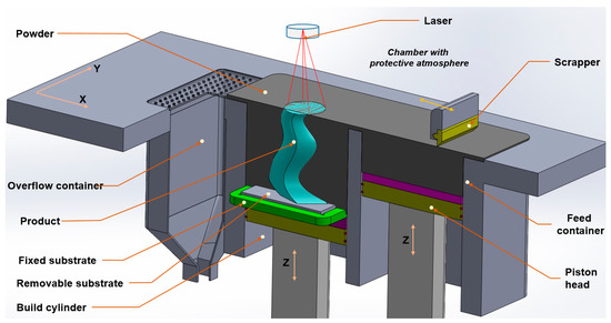
Figure 1.
The selective laser melting (SLM) printing process [11].
Flake Behavior
When investigating the printing process parameters of powder bed fusion printing, the ability to spread a sufficient new layer of powder is the major determinant of product quality. However, some unwanted behaviors may occur during the selective laser melting process. Delamination or cracking of the support section (shown by the dashed circles in Figure 2a,b) occur inside the printed part itself and are due to process parameters. However, the flaking shown in Figure 2c occurred because of material differences additionally.
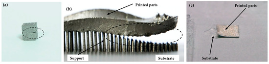
Figure 2.
Delamination (a), support cracking (b), and flaking (c).
Because of the flake, the printed section and the scrapper are conflicted. Therefore, the spreading process can create a problem; in the worst case, the SLM process must be stopped. Therefore, the flake phenomenon can represent the join quality of hybrid materials. In this study, the SLM process of pure aluminum powder on stainless steel 316 L substrate was analyzed by investigating the effects of process parameters and flake behavior.
2. Materials and Methods
In this study, 99.9% pure aluminum powder was printed on a stainless-steel 316 L substrate. The powder particle size of the aluminum powder was 30–45 µm. A scanning electron microscopy (SEM) image of the aluminum powder (HKK Solution Co., Ltd., Seoul, South Korea) is shown in Figure 3a. Figure 3b indicated the particle size distribution by the laser scattering analyzer LA-960. An SLM printer (MetalSys 150, WinforSys co., Ltd., Gyeonggi-do, South Korea) with an air-cooled ytterbium fiber laser (YLR-200-AC-Y11 IPG Ytterbium Fiber Laser, 200 W maximum output) was used for processing. Table 1 describes the technical parameters of the printer.
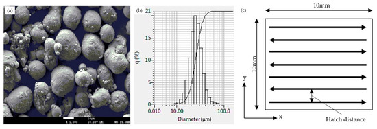
Figure 3.
(a) SEM image of pure aluminum powder particles, (b) powder particle size distribution, and (c) laser scanning strategy.

Table 1.
Technical parameters of the selective laser melting (SLM) MetalSys 150.
A series of aluminum cubes were printed on the stainless-steel substrate without support sections. All steel substrates investigated in this study were 10 mm thick to prevent deformation during processing. Prior to printing, the substrates were polished with 2000-grit paper and cleaned with ethanol. The printing process used the meander-scanning pattern shown in Figure 3c, in which the laser scan direction was parallel to the x-axis in every layer. Layer thickness was 20 µm for every experiment. The fabricating chamber was set at 28 °C initially. The argon gas was pumped into the chamber at 25 L/min of flow rate and 0.05 MPa of pressure to obtain an oxygen level below less than 0.1 percent. After achieving a setup oxygen level, the gas supply was cut off and atmosphere in the manufacturing chamber was recycled.
Because SLM printing is an accumulative process, the flake was evaluated by observing the quantity of possible printed layers before they reached the surface of the substrate. The printing process was stopped immediately at the occurrence of flake. After printing, the samples were cut using wire-cut electrical discharge machining. Then, they were hot-press embedded in an electro-conductive resin, ground with SiC abrasive paper with a grit range up to 4000, and polished with a diamond paste having an average grain size of 2 µm. Final polishing used a colloidal silica suspension of 0.04 µm. Scanning electron microscopy (SEM) and energy dispersive spectroscopy (EDS) were used for intermetallic observation and microstructural characterization.
3. Results and Discussion
3.1. Deformation in the Selective Laser Melting (SLM)
Due to the layer-by-layer principle of the SLM printing process, the printed section becomes increasingly thicker, and products are formed progressively. Therefore, to obtain a cubic thickness of 10 mm, the process must complete the riskiest period first, before a 10 × 10 mm plate of metal is formed.
Residual stress is always present in products printed by SLM [9,10], as presented in Figure 4. Because new layers are printed on other solidified layers, flake behavior is the result of an accumulative process. After printing a layer shown in Figure 4a, the solidified layers increase, creating a sheet indicated in Figure 4b. In the first several layers, the thickness of the printed layers was too thin; therefore, there was no steep temperature gradient with thickness. During heating, thermal compressive stresses develop in the printed layers, which results in a large amount of thermo-elastic strain, possibly producing local thermo-elasto-plastic buckling of the material. When the laser beam of the printer passes, the buckle is generated along the direction of laser scanning [13].
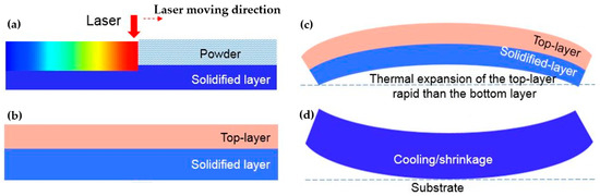
Figure 4.
Temperature gradient mechanism [11]: schematic of the SLM processing (a) created a new layer on other solidified layers (b), thermal expansion generated by heated new layer (c) and shrinkage process during cooling (d).
After achieving a certain thickness, because of heating, a steep thermal gradient in the manufactured layers leads to differences in thermal expansion throughout the thickness. At the initial stage, the top surface is heated because it faces the laser shown in Figure 4c. Rapid thermal expansion of the top solid layers in contrast to the bottom solid layers, as well as restriction by the surrounding material, creates a concave downward shape. At a certain temperature, the shape and degree of bending produce maximum elastic strain. Any additional thermal expansion is converted into plastic compression. After the laser moves away, cooling ensues, and shrinkage occurs shown in Figure 4d.
3.2. Intermetallic Layer
The printing process creates molten aluminum on the solid substrate. That aluminum melts on the solid surface of the substrate to create a diffusion area called an intermetallic layer, which exists as the interface between the printed section and the substrate. Formation of the intermetallic phases between the solid iron/steel and liquid aluminum depends on the chemical reaction and interdiffusion of the elemental constituents. Figure 5 demonstrates the SEM morphology and EDS mapping results of a sample, which indicate a distribution of Fe in Figure 5b and Al shown in Figure 5c elements. The results show that the Fe element diffused into molten aluminum to a larger extent than the Al element diffused into the stainless-steel substrate.
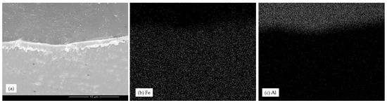
Figure 5.
(a) Energy dispersive spectroscopy (EDS) image, (b) Fe element distribution, and (c) Al element distribution.
Figure 6 shows an EDS point analysis of a flaked sample with 31.11 at% iron and 68.89 at% aluminum. The analysis confirms that the Fe2Al5 phase exists in the intermetallic layer. The results agree with previous research using other methods [14,15,16,17]. However, the morphology of the reaction layer during the SLM process is different from the previous methods. Although previous studies reported tongue-like, needle-like, or wave-like [18,19,20,21] morphology, the SLM process shows a more chaotic morphology of the reaction layer, as indicated in Figure 7. The chaotic morphology can be explained by the molten material flow during melting and evaporation during the SLM process [22]. Additionally, denudation [23], where a laser interacts with metal powder, results in non-repetitive formation of an intermetallic layer.
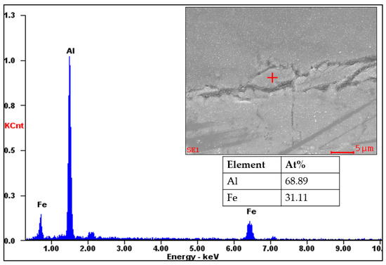
Figure 6.
Results of the EDS point analysis of the intermetallic layer of a flaked sample.
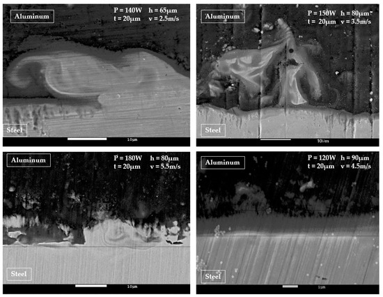
Figure 7.
Morphology of the intermetallic layers formed during the selective laser melting process.
The intermetallic layer thickness was determined by detecting the Fe-Al change, as shown by the two dashed lines in Figure 8. The thickness is associated with the SLM process parameters of time and temperature. An increase in laser power increases the thickness of the reaction layer, whereas an increase in laser speed decreases the thickness of the metallic layer. An increase in laser power causes an increase in energy and thus an increase in peak temperature. Higher temperatures and longer reaction times increase the thickness of the reaction layer. Moreover, a higher laser scanning velocity results in a lower peak temperature and leads to a reduced thickness of the bimetallic layer. The EDS results show that the thickness of the metallic layer ranges from 3 µm to 70 µm. When the intermetallic layer is thin, the mechanical performance of the joint is not yet detrimental, as shown in Figure 8a. However, the joint will fail when the reaction layer thickens, as shown in Figure 8b. These results agree with previous studies [24].

Figure 8.
Intermetallic layer thickness determined by EDS line mapping analysis: (a) a thin intermetallic layer [11] and (b) a thick reaction layer that creates a flake.
3.3. Influence of Process Parameters on Join Quality of Dissimilar Materials
In the SLM process, the intermetallic reaction layer plays a crucial role against the residual stress generated by the thermal gradient. The intermetallic layer is brittle in the area close to the side of the substrate [25], and the strength depends on its thickness. A thinner intermetallic layer has greater strength, and vice versa. Therefore, to prevent a low joining strength, the thickness of the reaction layer should be limited [26]. The flake behavior was investigated by observing the number of layers that could be printed before flaking occurred. Figure 9 shows the experimental results of the observed quantities of printed layers in the boundary area in which the flaking occurred.
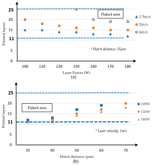
Figure 9.
Effects of laser power (a), and hatch distance (b) on flaking.
At the beginning of the process, when the printed section is not thick enough, residual stress from the thermal gradient in the X and Y directions is overwhelming; thus, an intermetallic layer can prevent cracking. Our experiment showed that flaking appeared around the 11th layer but no sooner. When the printed section became increasingly thicker, the temperature difference between the top and intermetallic layers was greater. The intermetallic layer also suffers from greater residual stress created by the thermal gradient in the thickness direction. However, when the printed section achieved a certain thickness, the effect of the top layer on the intermetallic layer was reduced, and the risk of flaking decreased. It is reasonable to assume that further flaking did not occur after the 25th layer.
Figure 9a demonstrates the laser power effect at 1.5 m/s, 2 m/s, and 4 m/s presented by the triangle, circle, and rectangle makers, respectively. As shown, the printed layers decreased when the laser power increased. Increasing laser power results in a high peak temperature, increasing the residual stress by increasing the thermal transient in each layer. Increasing laser power results in a flaked happening sooner. Figure 9a also shows that, at a fixed laser power, flaking occurred also sooner at a lower laser scanning speed. At a certain printed thickness, a lower laser velocity creates a weaker thermal transient between the top layer and intermetallic layers, reducing residual stress. Additionally, a reduction in laser velocity raised the peak temperature. Higher temperatures and longer reaction times lead to an increase of reaction layer thickness and an easier flaked appearance.
The influence of hatch distance on flaking is shown in Figure 9b. Laser power was investigated at 100 W, 150 W and 180 W displayed by the rectangle, circle and triangle shapes, respectively. Increasing the hatch distance increased the number of layers that could be printed. Increasing the hatch distance also reduced the heating time in certain printed areas, reducing the thermal transient in a printing layer and residual stress.
The function of the intermetallic layer is to act as protection against the residual stress force. As mentioned in the previous section, high temperature tends to cause concave bending in the printed layers, which leads to the flake phenomenon. The initial residual stress force is not enough to disrupt the surface of the substrate because of the thin printed layers. During accumulative processes, an increase of printed layers causes the residual stress force to increase. With an unsuitable process parameter, the residual stress force overwhelms the opposing force existing in the intermetallic layers and leads to flaking. However, when the printed layers achieve a certain thickness, concave bending transforms into convex bending [27], which is an advantage of flaking. In our case, experimental results show that the 11th and 25th layers are the lower and upper boundaries of flaking behavior, respectively.
3.4. Join Quality in Term of Energy
Relationship between supplied energy and join quality was investigated. The energy, E, is described by laser power, P, and volume of molten material, V, as . Other studies [28,29] calculated energy as follows:
Here, v, h, and t are laser scanning speed, hatch spacing, and layer thickness, respectively. However, Equation (1) can present a rough estimation for comparable process parameters [30]. Meanwhile, by assuming that the melt tracks are semi-circular, energy is calculated as follows [31]:
Figure 10a,b illustrates a comparison between experimental observation and energy calculated by , respectively. The orange color represents a flaked area, whereas the green color represents a non-flaked area. In this case, laser power was kept at 180 W and layer thickness was fixed at 20 µm. The results indicate that it is easier to obtain a good joining when laser velocity and hatch distance are increased, as mentioned in Figure 9. This can be explained by a decrease in the reaction layer when laser scanning speed and hatch space are increased, or energy is reduced. The diagonal stripes in Figure 10 indicate energy calculated by the formulas. The diagonal striped areas cover not only the non-flaked area, but also broadly cover the flaked space. The more covering of the flaked area, the less the accuracy of the formula. Figure 10a,b indicate that the energy formulas cannot be used to describe the flake behavior and become less accurate as the flaked area increases.
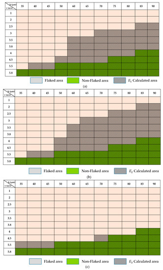
Figure 10.
Comparison between experimental results and energy calculated by (a) , (b) and (c) formulas.
Moreover, in the SLM process, hatch overlap () was investigated as an important parameter [32] (here, d is laser spot size). Figure 11 illustrated the effect of the hatch overlap. The current line track nth of a laser generates a post-heating zone during printing, which reheats the solidified material of the last scan line n − 1th, as well as a pre-heating zone, which affects the melting process of the next scanning line n + 1th. Finally, hatch overlap affects melt geometry, heat-affected zone, formation of a solidification microstructure, and residual stress. In this analysis, the hatch overlap parameter was considered to affect energy. Combined with the assumption that the melt track is semi-circular, the following formula was generated:
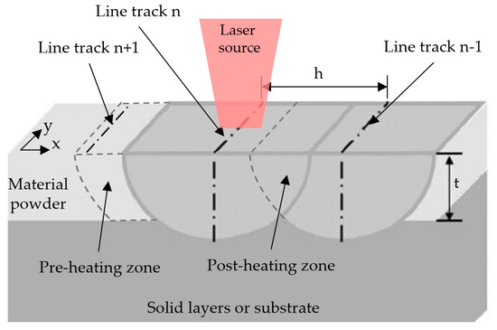
Figure 11.
Schematic representation of the hatch overlap effect.
Figure 10c illustrates the fit of the formula calculation and experimental area. Although there is an existing small gap between the calculated area and experimental result, the formula could be applied to determine the relationships between joining quality and process parameters in terms of energy.
4. Conclusions
Joining of pure aluminum and stainless steel by the SLM printing process was analyzed. In the SLM method, the flake behavior could be represented by Al-Fe join strength. Process parameters such as laser power, laser scanning speed, and hatch distance significantly affect the final hybrid-material join quality. The results indicate a high-risk area between the 11th and 25th layers, where we should be most concerned about flaking behavior. After the 25th layer, bimetallic joining can be guaranteed. The intermetallic layer plays a significant role in the combination of hybrid materials by the SLM process. The results showed the Fe2Al5 phase existing in the intermetallic layer of the flaked samples. That was agreed with other joining methods. The research figured out the dependence of the flake behavior and the applied energy: the increasing energy leads to a sooner disruption the join. The research found out that the hatch overlap affected to Al-Fe join strength. Based on investigating the hatch overlap as an effective factor, the formula can be used to estimate the approximate values of process parameters to achieve a good join quality of aluminum and stainless steel.
Author Contributions
D.-S.N. and H.-S.P. conceived the idea of this study. D.-S.N. developed, validated, and performed the experimental works. D.-S.N. wrote the manuscript and H.-S.P. and C.-M.L. revised it. All authors discussed the results and commented on the manuscript.
Funding
This work was supported by the ICT R&D program of MSIP/IITP [B0101-14-1081, Development of ICT-based software platforms and service technologies for medical 3D printing application].
Conflicts of Interest
The authors declare no conflicts of interest.
References
- Liyanage, T.; Kilbourne, J.; Gerlich, A.P.; North, T.H. Joint Formation in Dissimilar Al Alloy/Steel and Mg Alloy/Steel Friction Stir Spot Welds. Sci. Technol. Weld. Join. 2009, 14, 500–508. [Google Scholar] [CrossRef]
- Taban, E.; Gould, J.E.; Lippold, J.C. Dissimilar Friction Welding of 6061-T6 Aluminum and AISI 1018 Steel: Properties and Microstructural Characterization. Mater. Des. 2010, 31, 2305–2311. [Google Scholar] [CrossRef]
- Li, J.; Li, H.; Huang, C.; Xiang, T.; Ni, Y.; Wei, H. Welding Process Characteristics of Pulse on Pulse MIG Arc Brazing of Aluminum Alloy to Stainless Steel. Int. J. Adv. Manuf. Technol. 2017, 91, 1057–1067. [Google Scholar] [CrossRef]
- Arivazhagan, N.; Singh, S.; Prakash, S.; Reddy, G.M. Investigation on AISI 304 Austenitic Stainless Steel to AISI 4140 Low Alloy Steel Dissimilar Joints by Gas Tungsten Arc, Electron Beam and Friction Welding. Mater. Des. 2011, 32, 3036–3050. [Google Scholar] [CrossRef]
- Pardal, G.; Meco, S.; Ganguly, S.; Williams, S.; Prangnell, P. Dissimilar Metal Laser Spot Joining of Steel to Aluminium in Conduction Mode. Int. J. Adv. Manuf. Technol. 2014, 73, 365–373. [Google Scholar] [CrossRef]
- Yang, J.; Chen, J.; Zhao, W.; Zhang, P.; Yu, Z.; Li, Y.; Zeng, Z.; Zhou, N. Diode Laser Welding/Brazing of Aluminum Alloy to Steel Using a Nickel Coating. Appl. Sci. 2018, 8, 922. [Google Scholar] [CrossRef]
- Mehrpouya, M.; Gisario, A.; Barletta, M.; Natali, S.; Veniali, F. Dissimilar Laser Welding of NiTi Wires. Lasers Manuf. Mater. Process. 2019, 6, 99–112. [Google Scholar] [CrossRef]
- Tomashchuk, I.; Grevey, D.; Sallamand, P. Dissimilar Laser Welding of AISI 316L Stainless Steel to Ti6-Al4-6V Alloy via Pure Vanadium Interlayer. Mater. Sci. Eng. A 2015, 622, 37–45. [Google Scholar] [CrossRef]
- Mehrpouya, M.; Gisario, A.; Broggiato, G.B.; Puopolo, M.; Vesco, S.; Barletta, M. Effect of Welding Parameters on Functionality of Dissimilar Laser-Welded NiTi Superelastic (SE) to Shape Memory Effect (SME) Wires. Int. J. Adv. Manuf. Technol. 2019, 103, 1593–1601. [Google Scholar] [CrossRef]
- Tanaka, Y.; Kajihara, M. Kinetics of Isothermal Reactive Diffusion between Solid Fe and Liquid Al. J. Mater. Sci. 2010, 45, 5676–5684. [Google Scholar] [CrossRef]
- Park, H.S.; Nguyen, D.S. Study on Flaking Behavior in Selective Laser Melting Process. Procedia CIRP 2017, 63, 569–572. [Google Scholar] [CrossRef]
- Santos, L.; de Jesus, J.; Ferreira, J.; Costa, J.; Capela, C. Fracture Toughness of Hybrid Components with Selective Laser Melting 18Ni300 Steel Parts. Appl. Sci. 2018, 8, 1879. [Google Scholar] [CrossRef]
- Kruth, J.P.; Leu, M.C.; Nakagawa, T. Progress in Additive Manufacturing and Rapid Prototyping. CIRP Ann. Manuf. Technol. 1998, 47, 525–540. [Google Scholar] [CrossRef]
- Demir, A.G.; Previtali, B. Multi-Material Selective Laser Melting of Fe/Al-12Si Components. Manuf. Lett. 2017, 11, 8–11. [Google Scholar] [CrossRef]
- Shishkovsky, I.; Missemer, F.; Kakovkina, N.; Smurov, I. Intermetallics Synthesis in the Fe–Al System via Layer by Layer 3D Laser Cladding. Crystals 2013, 3, 517–529. [Google Scholar] [CrossRef]
- Kempen, K.; Vrancken, B.; Buls, S.; Thijs, L.; Van Humbeeck, J.; Kruth, J.P. Selective Laser Melting of Crack-Free High Density M2 High Speed Steel Parts by Baseplate Preheating. J. Manuf. Sci. Eng. 2014, 136, 061026. [Google Scholar] [CrossRef]
- Zhang, M.; Liu, C.; Shi, X.; Chen, X.; Chen, C.; Zuo, J.; Lu, J.; Ma, S. Residual Stress, Defects and Grain Morphology of Ti-6Al-4V Alloy Produced by Ultrasonic Impact Treatment Assisted Selective Laser Melting. Appl. Sci. 2016, 6, 304. [Google Scholar] [CrossRef]
- Tanaka, Y.; Kajihara, M. Morphology of Compounds Formed by Isothermal Reactive Diffusion between Solid Fe and Liquid Al. Mater. Trans. 2009, 50, 2212–2220. [Google Scholar] [CrossRef]
- Peyre, P.; Sierra, G.; Deschaux-Beaume, F.; Stuart, D.; Fras, G. Generation of Aluminium-Steel Joints with Laser-Induced Reactive Wetting. Mater. Sci. Eng. A 2007, 444, 327–338. [Google Scholar] [CrossRef]
- Eggeler, G.; Auer, W.; Kaesche, H. On the Influence of Silicon on the Growth of the Alloy Layer during Hot Dip Aluminizing. J. Mater. Sci. 1986, 21, 3348–3350. [Google Scholar] [CrossRef]
- Pasche, G.; Scheel, M.; Schäublin, R.; Hébert, C.; Rappaz, M.; Hessler-Wyser, A. Time-Resolved X-ray Microtomography Observation of Intermetallic Formation between Solid Fe and Liquid Al. Metall. Mater. Trans. A Phys. Metall. Mater. Sci. 2013, 44, 4119–4123. [Google Scholar] [CrossRef]
- Verhaeghe, F.; Craeghs, T.; Heulens, J.; Pandelaers, L. A Pragmatic Model for Selective Laser Melting with Evaporation. Acta Mater. 2009, 57, 6006–6012. [Google Scholar] [CrossRef]
- Matthews, M.J.; Guss, G.; Khairallah, S.A.; Rubenchik, A.M.; Depond, P.J.; King, W.E. Denudation of Metal Powder Layers in Laser Powder Bed Fusion Processes. Acta Mater. 2016, 114, 33–42. [Google Scholar] [CrossRef]
- Achar, D.R.G.; Ruge, J.; Sundaresan, S. Metallugical and Mechanical Investigations of Aluminium-Steel Fusion Welds (I). Alum. Dusseld. 1980, 56, 391–397. [Google Scholar]
- Rathod, M.J.; Kutsuna, M. Joining of Aluminum Alloy 5052 and Low-Carbon Steel by Laser Roll Welding. Weld. Res. 2004, 83, 16S–26S. [Google Scholar]
- Borrisutthekul, R.; Yachi, T.; Miyashita, Y.; Mutoh, Y. Suppression of Intermetallic Reaction Layer Formation by Controlling Heat Flow in Dissimilar Joining of Steel and Aluminum Alloy. Mater. Sci. Eng. A 2007, 467, 108–113l. [Google Scholar] [CrossRef]
- Hu, Y.; Xu, X.; Yao, Z.; Hu, J. Laser Peen Forming Induced Two Way Bending of Thin Sheet Metals and Its Mechanisms. J. Appl. Phys. 2010, 108, 073117. [Google Scholar] [CrossRef]
- Shah, L.H.; Ishak, M. Review of Research Progress on Aluminum-Steel Dissimilar Welding. Mater. Manuf. Process. 2014, 29, 928–933. [Google Scholar] [CrossRef]
- Yusuf, S.M.; Gao, N. Influence of Energy Density on Metallurgy and Properties in Metal Additive Manufacturing. Mater. Sci. Technol. 2017, 33, 1269–1289. [Google Scholar] [CrossRef]
- Hagedorn, Y. Additive Manufacturing of High Performance Oxide Ceramics via Selective Laser Melting; RWTH Aachen University: Berlin, Germany, 2013. [Google Scholar]
- Yap, C.Y.; Chua, C.K.; Dong, Z.L. An Effective Analytical Model of Selective Laser Melting. Virtual Phys. Prototyp. 2016, 11, 21–26. [Google Scholar] [CrossRef]
- Criales, L.E.; Arısoy, Y.M.; Özel, T. A Sensitivity Analysis Study on the Material Properties and Process Parameters for Selective Laser Melting of Inconel 625. Am. Soc. Mech. Eng. 2015, 86, V001T02A062. [Google Scholar]
© 2019 by the authors. Licensee MDPI, Basel, Switzerland. This article is an open access article distributed under the terms and conditions of the Creative Commons Attribution (CC BY) license (http://creativecommons.org/licenses/by/4.0/).