1. Introduction
Selective laser melting (SLM), which belongs to the category of powder bed fusion [
1], is one of the fastest growing additive manufacturing (AM) technologies globally. It allows producing metal components with complex geometry, resulting in severely reduced design and production times of the entire productive process [
2].
During the fabrication, metallic powders are uniformly spread on a building platform by a re-coater creating the powder bed; a focused laser beam scans it, according to the designed path, selectively melting the powders [
3]. After the consolidation of this layer, the building platform lowers, and the process is repeated until the part is completed.
The Wohlers report [
4] indicated that 1768 metal AM systems were sold in 2017, a surge of nearly 80% compared to the previous year (983 systems in 2016). This rapid growth is due to the development of new functional applications in different fields such as aerospace, biomedical, defense, automotive, and many other industries thanks to the benefits offered by metal AM with respect to conventional manufacturing technologies. [
5]. In particular, SLM permits producing fully dense parts in a direct way, thereby saving on raw material with respect to subtractive technologies [
6]. It promotes the possibility of producing customized metal components in a cost-effective manner, allowing great flexibility in production; the design freedom allows improving the efficiency [
7] and the functionality [
8,
9] of existing designs, as well as the possibility to incorporate more complex features without drastically increasing the costs. This aspect includes the possibility to create features not fabricable conventionally, such as internal structures, e.g., lattice structures [
10] or channels [
11]. SLM permits shortening the supply chain and the lead time by replacing some production processes with a single step or combining different sub-elements in a single component [
12,
13], thereby reducing or in some cases eliminating the assembly operations.
Despite these advantages, the limitations for the complete implementation of this technology in the industrial framework are its low productivity and the presence of defects such as porosity, high residual stresses, cracks, inclusions, and surface irregularities that affect the structural integrity and surface quality of an SLM part [
14]. In particular, the poor surface finishing and the surface anisotropy [
15] are crucial aspects to consider. Typically, in order to improve the surface quality, the SLM surfaces are treated by different post-processing operations such as sand blasting, shoot peening, electropolishing, chemical polishing, and grinding [
16]. These operations are skilled operator-dependent, labor-intensive, and typically hard to apply uniformly on complex-shaped parts. In Reference [
17], the effect of the post-processing by machining, vibratory finishing, and drag finishing on the surface quality of SLM parts was investigated. The results showed that machining was the best choice because it permitted obtaining very high surface quality in a deterministic way, but it was limited by complex shapes. In the comparison between drag finishing and vibratory finishing, lower roughness values were observed for the former; however, the operation was limited by the need for fixturing the parts. In Reference [
18], a magnetic abrasive finishing process was developed to polish SLM planar parts. The results showed that the method removes partially bonded particles and balling defects, obtaining a maximum decrease of about 76% in surface roughness. The system is suitable for planar surfaces but hardly applicable to complex shapes. In Reference [
19], cavitation combined with abrasion was used as an SLM finishing process, leading to a reduction in Ra below 4 µm for external surfaces and internal channels 3 mm in diameter.
Barrel finishing (BF) is the most ancient mass finishing operation, which allows conditioning the part’s surface without fixturing: this degree of freedom meets AM’s major aim of being almost independent of part geometry [
20]. Notwithstanding its slow process, BF is vastly used because it is a versatile conditioning method with low-cost equipment [
21]. The process is typically performed via an octagonal rotating barrel; the charge, composed of the parts, media, water, and a compound, is moved upward by rotation until a critical angle is reached; hence, a layer slides down. Within this region, namely, the active layer, a relative velocity between parts and media takes place, leading to a delicate abrasive conditioning of the part surfaces. Unfortunately, a specific motion is required for this behavior; thus, particular conditions must be satisfied by using adequate processing parameters [
21]. The difficulty lies in the prediction of the flow properties in granular material motions, characterized by an intrinsic complexity of the element laws and a very large number of elements interacting with each other [
22]. The elements are discontinuous and highly heterogeneous, and a dilatant behavior under shearing modifies the interactions, leading to an extreme variety of natural phenomena [
23]. There is an extensive experimental database on the properties of non-cohesive granular material flow [
24]. As early as 1954, Bagnold stated that the tangential stresses in an intensive shear flow are mainly caused by two factors: particle collisions and impulse interchange between different layers [
25]. In his pioneering work, a relevant characterization of dynamic regimes was carried out. He found that the ratio between interparticle collision forces and interstitial viscous forces leads to two different regimes, namely, macroviscous and grain-inertial regimes. This ratio, called the Bagnold number (
), is defined as follows:
where
is the particle mass,
is the average velocity gradient along the active layer depth,
is the characteristic length, and
is the dynamic viscosity of the interstitial fluid.
In the case of small
(less than 40), the flow is macroviscous, such as flows of slurries or mud, where the interstitial fluid viscosity overcomes the grain inertia. For
greater than 450, the fluid viscosity can be neglected in comparison with the interparticle collisions; then, a grain-inertial flow takes place. A transitional regime falls between these two values [
26].
Six different motions are defined in the literature, i.e., sliding, slumping, rolling, cascading, cataracting, and centrifuging, which are based on variations in the filling and the rotational speed of the barrel. No model exists for the prediction of process parameters to obtain these motions, because they are strictly dependent on the used charge in terms of material and shape, filling percentage, quantity of water and compound, etc. For this reason, the study of BF motions and process parameters is typically developed using bed behavior (BB) diagrams [
27]. These are maps of the six motions and their transitions as a function of the filling percentage and the rotational speed of the barrel. These maps must be experimentally obtained because they change with the employed charge. The individuation of the motions and the relative process parameters is fundamental for the design of the BF process because only two motions, i.e., rolling and cascading, permit having an efficient material removal. These motions are characterized by a delicate continuous flow in the form of an avalanche that realizes relative motions between the media and parts being processed, causing a soft mechanical removal of material. The action was modeled in Reference [
28], where the authors underlined that, during the BF process, the micro-geometrical profile is gradually cut away from peak to valley without plastic deformation.
In Reference [
29], this process was successfully applied to SLM parts, reaching uniform surface morphologies on planar surfaces characterized by different build orientations; however, the case of functional parts characterized by complex shapes was not investigated. In Reference [
30], a turbine blade manufactured in Inconel718 by SLM was processed by BF and other post-processing treatments. The results showed that the BF application permitted a slight improvement in the surface quality compared to the other studied processes. It is our opinion that, in this paper, the potential of the BF process was not exploited because of the lack of a deep study of the charge and the process parameters.
The aim of this paper was to develop a methodology for the design of the BF process specifically applied to SLM parts. The methodology consisted of the study of different charges in the exploration of various process parameter sets in order to find a suitable technological window. These sets were used to condition complex SLM parts fabricated into two different materials.
2. Materials and Methods
The experimental activities reported in this paper were divided into three phases. The first was a preliminary experimentation necessary for the study of BF regimes. The output was the selection of many process parameter sets that assured the rolling and cascading regimes for the different considered charges. These parameters were used in the second phase to study the BF action on SLM specimens characterized by a simple shape and different materials. The results in terms of roughness measurements were used to select efficient BF process parameters for the finishing of two functional components (third phase).
2.1. Materials
For the fabrication of the SLM specimens and the complex components, the employed machine was an EOSINT® M290 characterized by a building volume of 250 × 250 × 325 mm3 and a 400-W ytterbium fiber continuum laser, with a beam spot diameter of 100 μm. The process was carried out in an argon inert atmosphere with less than 0.1% oxygen. The building platform was preheated at 200 °C in order to reduce residual stresses.
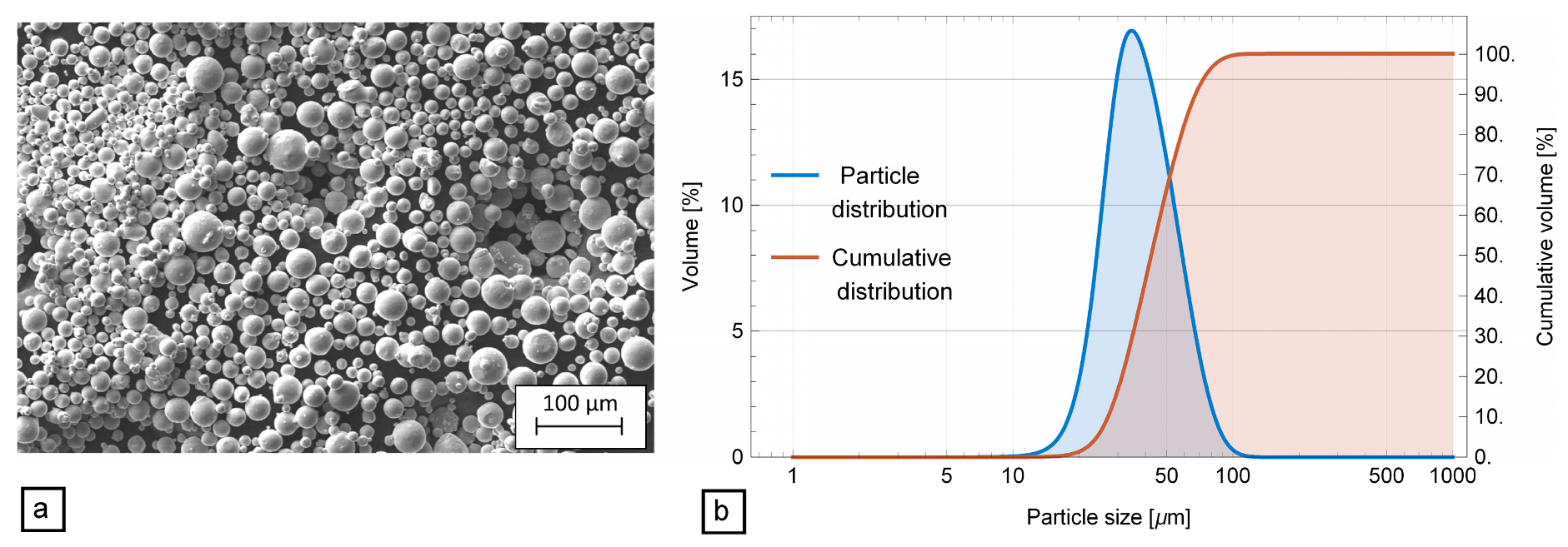
The first material was Ti6Al4V, characterized by the chemical composition reported in
Table 1. In
Figure 1, the SEM image and the granulometry distribution of the employed powders are reported. The shape of the particles was highly spherical, and a large scattering of diameters could be observed (
Figure 1a). As shown in
Figure 1b, this distribution (blue curve) was asymmetrical, and the corresponding cumulative volume (red curve) was characterized by the following metrics: d
10, d
50, and d
90, which were the intercepts for 10%, 50%, and 90%, paired to 27.1 µm, 42.5 µm, and 67.8 µm, respectively.
The used process parameters were as follows: 30 μm layer thickness, 140 μm hatch spacing, 1200 mm/s scan speed, and 280 W laser power. The scanning strategy was the stripe type, with a stripe length and an overlap of 5 mm and 0 mm, respectively. The scanning direction was rotated between consecutive layers by 67° in order to minimize the out-of-plane distortion. The detaching from the building platform was performed by abrasive cutting, and no other finishing operation was performed.
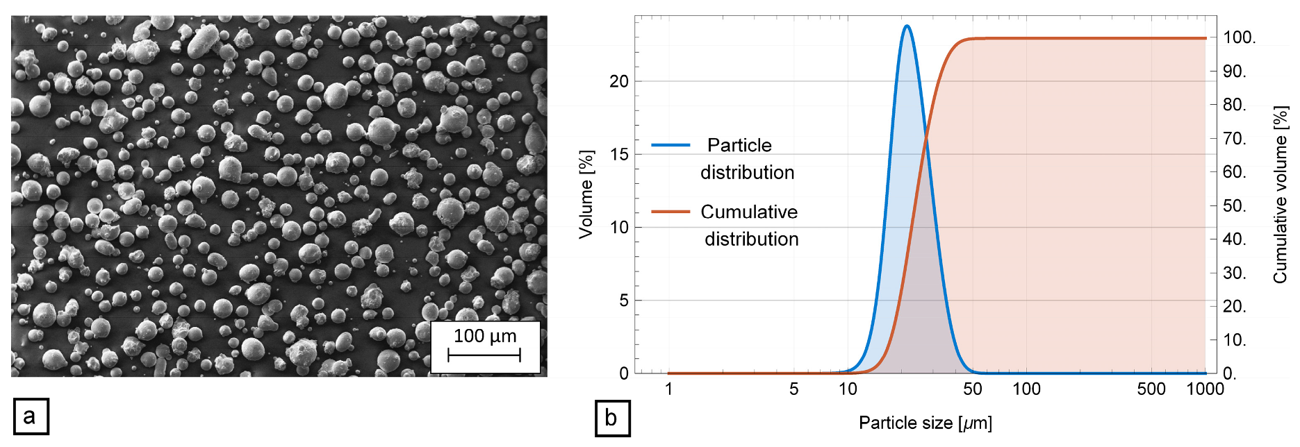
The second considered material was Inconel718; this powder is shown in the SEM image of
Figure 2a, highlighting an almost spherical shape with some oblong particles and aggregates. Its granulometry distribution was narrower than that of Ti6Al4V (
Figure 2b); in this case, the d
10, d
50, and d
90 corresponded to 17.3 µm, 23.7 µm, and 33.4 µm respectively.
Table 2 displays its chemical composition.
The applied process parameters were as follows: laser power 285 W, layer thickness 40 µm, scan speed 960 mm/s, and hatch spacing 110 µm. Furthermore, in this case the scan strategy was the stripe type, with a stripe length and an overlap of 10 mm and 0.8 mm, respectively.
The BF process was carried out using an industrial equipment Rotar EMI 47 (second and third phases); it is an eccentric-flow rotating barrel with an inclined octagonal section 400 mm in diameter moved by an asynchronous motor with a variable shift speed electric control system. The volume of the barrel was 47 L, and the maximum filling was 64 kg.
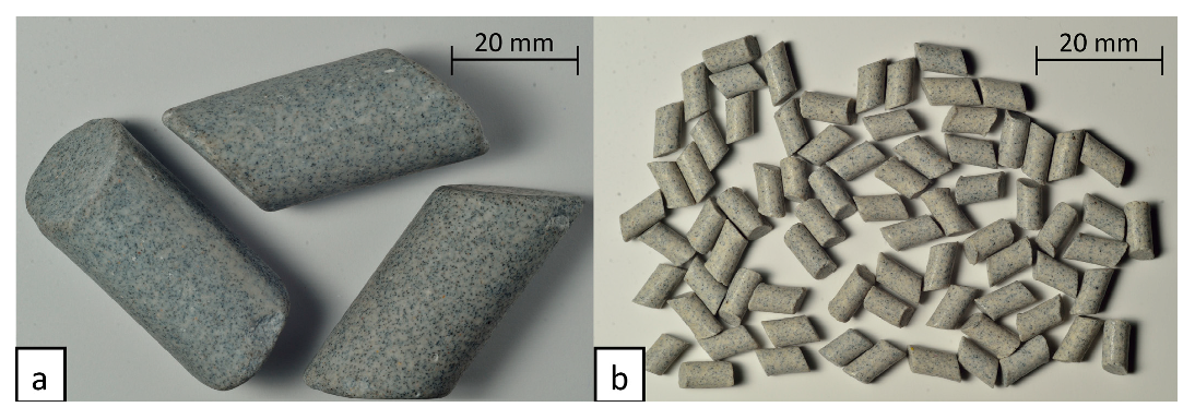
The employed charges were composed of media with the same shape but different size; the shape was angled cut cylindrical and the dimensions were 15 mm in diameter, 25 mm in height (
Figure 3a) and 3.5 mm in diameter, 10 mm in height (
Figure 3b). The composition of both media was a matrix of a synthetic resin and powders of alumina, silica, and silicon carbide as abrasive. The different sizes were suitable for the processing of complex shapes because the bigger media allowed speeding up the machining of the external surfaces, whereas the smaller media allowed reaching the internal surfaces or overhang zones, where there was not enough space for the relative motion of the bigger media. In the experimentation, three different charge types were considered: only big media (charge 1), only small media (charge 3), and a 50:50 volume fraction mixture of both (charge 2).
In order to determine the flow regimes and achieve important motion features, in the first phase, an experimental apparatus was employed. The barrel geometry and the internal material lining were the same of the industrial barrel. In this way, it was expected that the same motion regime could be observed on both barrels loaded with the same charge, employing the same process parameters. A transparent porthole allowed watching the motions and taking measures through digital image processing. The barrel was loaded with different filling percentages (from 30% to 60%). The rotational speed was controlled using a Yaskawa VS606V7 programmable drive; it was programmed with a linear ramp in order to cover the range speed of 0–110 rpm. A digital camera was employed for video acquisition of the motions and their transients, and a video editing software was used to classify them.
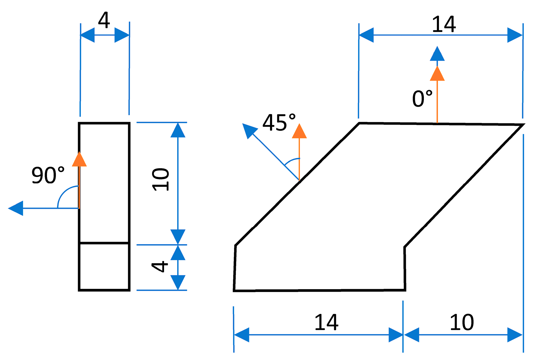
In the second phase, the considered specimen shape was as reported in
Figure 4. In order to evaluate the effect of the BF on different surface morphologies, the measured zones were the surfaces characterized by three different inclinations (0°, 90°, and 45°) with respect to the stratification direction. These specimens were fabricated with both considered materials.
The roughness measurements were performed using a Mitutoyo Surftest SJ-412 according to Reference [
31]; the sampling length and the evaluation length were set to 2.5 and 12.5 mm, respectively. A 2-μm stylus, sampling every 1.5 μm, was employed. The data were processed by a spline profile filter [
32] with a cut-off λc and a short wavelength cut-off λs equal to 2.5 mm and 8 μm, respectively. ISO standard roughness parameters were calculated, and the material-to-air ratio [
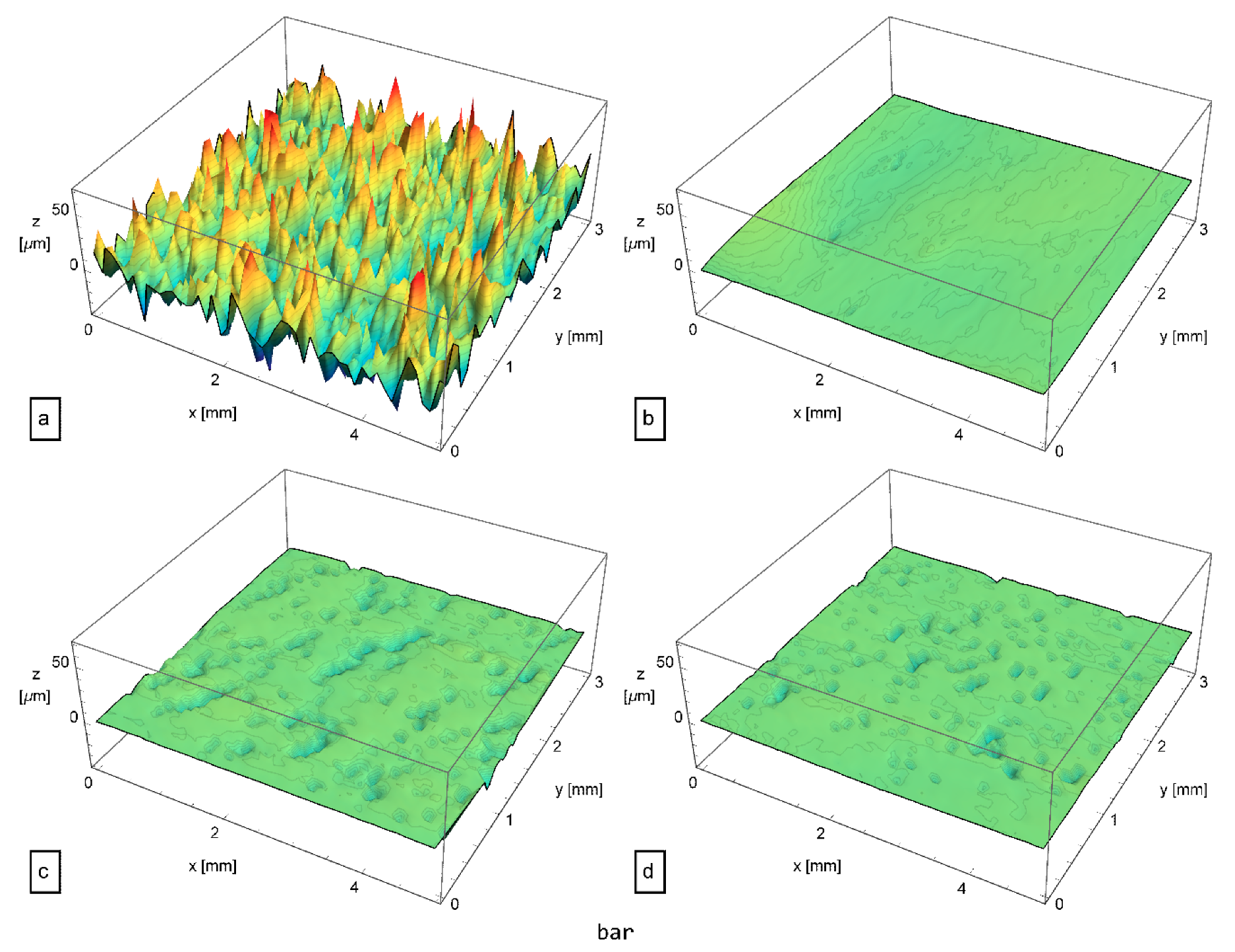
33], previously known as the Abbott–Firestone curve (AFC), was developed. Moreover, three-dimensional (3D) maps of 5 × 3 mm
2 were acquired, and the arithmetical mean absolute height (Sa) and the maximum height (Sz) were calculated according to Reference [
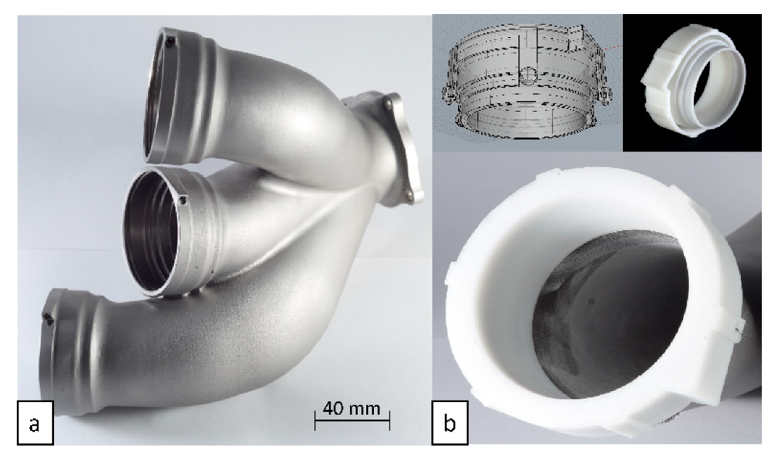
34]. The components characterized by complex shapes used in the third phase are described in
Section 5.
2.2. Methods
The experimental barrel was employed to define granular flow regimes at different rotating speeds for different charge compositions. Each charge was loaded in the barrel with different filling percentages, since they may affect the flow regime.
For each charge, the filling percentage was varied, and a video at different speeds was recorded and analyzed. In
Table 3, the complete set of these experiments is reported.
The gradient speed and the active layer depth were measured in order to calculate the number and to assess the type of regime. Afterward, the results allowed determining some conditions for grain-inertial flow, which is probably the preferred condition for efficient BF operation. The experimental apparatus was then employed to determine the motions in different processing conditions. Through a visual investigation, they were classified and, accordingly, the BBs were developed. Hence, the process parameters providing rolling and cascading regimes were properly selected.
3. First Phase of Experimentation: Results and Discussion
This phase aimed to study the BF regimes in order to find suitable process parameters for the considered charges.
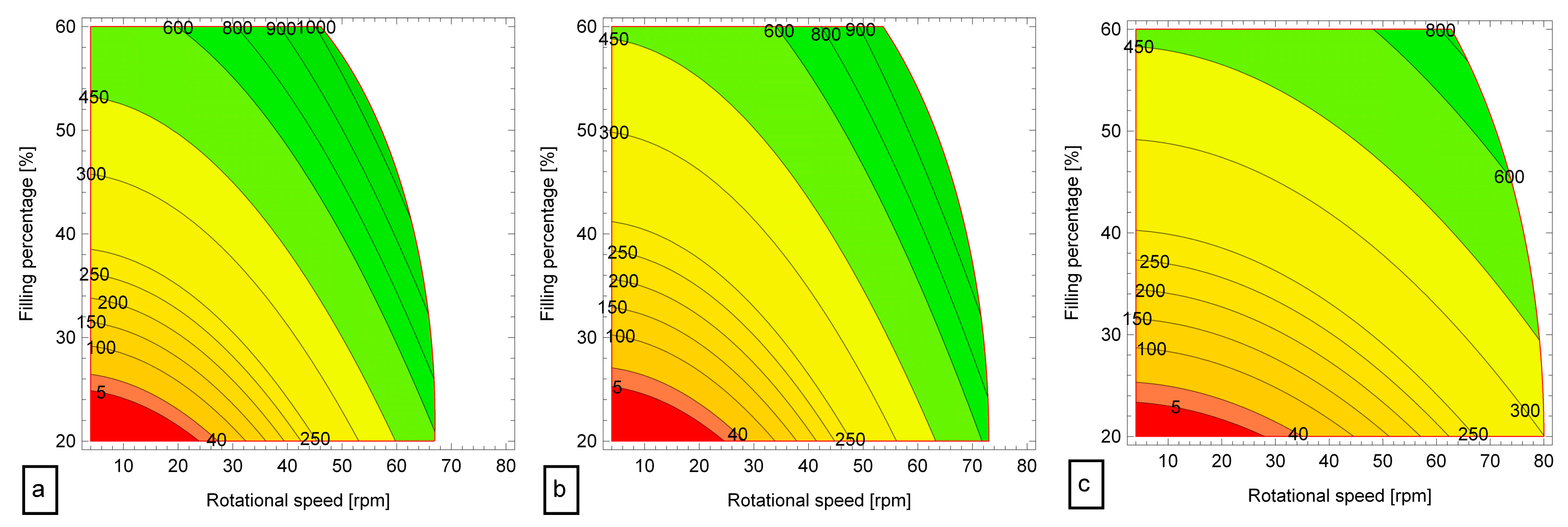
The evaluation of
for several levels of the processing parameters allowed development of the contour maps shown in
Figure 5. The red area is related to the macro-viscous behavior (
less than 40), while the green one refers to
greater than 450, corresponding to a grain-inertial flow; the transition between them is colored in yellow. The charge composed of only big media (
Figure 5a) dissipated energy in the viscous fluid only at low rotational speed and for low filling percentage. At high barrel filling, it was easy to find an inertial flow regime; however, for higher rotation, the media particles were no longer in contact and were launched toward the barrel walls, according to the definition of cataracting motion. In this condition, the
could not be evaluated, and a blank area is reported in the graph. For charge 2 (
Figure 5b), a similar behavior was observed; the granular flow was maintained at higher rotational speed with respect to charge 1 but a slight decrease in the green area was present. When charge 3 was employed, the experiment on the laboratory BF machine showed that the grain-inertial flow was limited to a combination of high filling and high rotational speed (
Figure 5c). This implies that the particle kinetic energy was mainly dissipated in the viscous fluid rather than interparticle interactions.
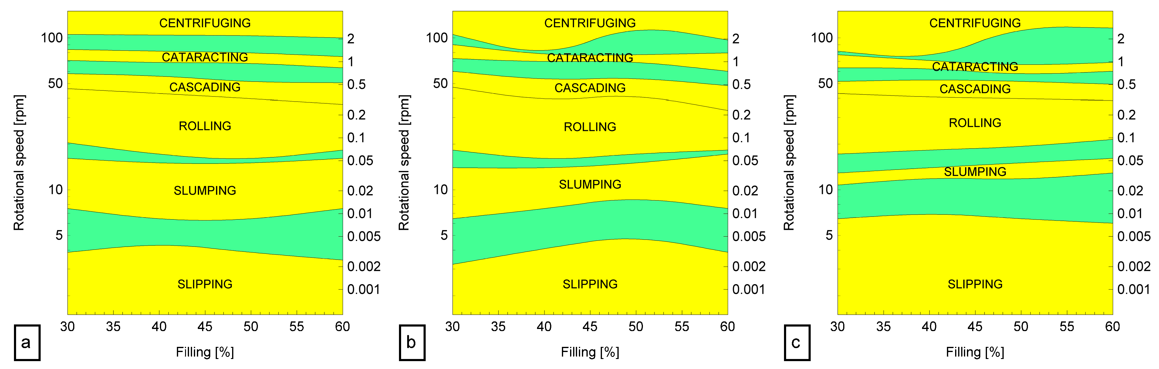
As mentioned above, rolling and cascading motions are required for BF operation. For this purpose, morphological analysis allowed the classification of flow behavior and the development of BB. In
Figure 6, the yellow and green areas indicate the six possible motions and their transitions. At low rotational speed, it is evident that charge 3 was characterized by high fluidity, i.e., the capability to move as a fluid; thus, a slipping motion was observed for a wide range of the speed. This may indicate that the charge can be placed with ease in complex geometrical features, but it could suffer from a reduction in kinetic energy. Charge 1 was characterized by slumping for speed in the range 7–20 rpm and a maximum extension of the area at 45% filling. Conversely, charge 3 showed a narrow slumping domain, highlighting that this charge is unable to maintain the peculiar periodic behavior, i.e., the frequency of the avalanche.
With regard to rolling, charge 1 and 2 had their lower limits at 50% and 40% respectively; this is in accordance with the best practice of approximately 50% filling percentage and a low Froude number, i.e., on the order of 0.1. The experiment with charge 3 shows that the minimum was observed at the smallest filling percentage, and it tended to increase with this variable. An extension of the rolling involved cascading where the charge-free surface was affected by the inertial forces and tended to be curved. The upper limit of charge 1 and 2 slightly decreased with filling percentage, while it was quite constant for charge 3; it can be assessed that the cascading/cataracting transition, characterized by the undesired launching of media, was avoided at a Froude number less than 0.5.
The BB diagrams allowed selecting process parameter values for the investigated charges. The rolling regime was assured by adopting a 25-rpm rotational speed. Two different filling percentages, i.e., 40% and 55%, were selected, as indicated in
Figure 7 with the parameter sets 3 and 4. The other two conditions were considered in order to provide a cascading motion, i.e., parameter sets 1 and 2 were assigned to filling percentages of 40% and 55%, respectively, at a rotating speed of 45 rpm.
4. Second Phase of Experimentation: Results and Discussion
The industrial BF machine was used according to the previously described method. Each specimen (
Figure 4) was extracted and measured by means of roughness measurement.
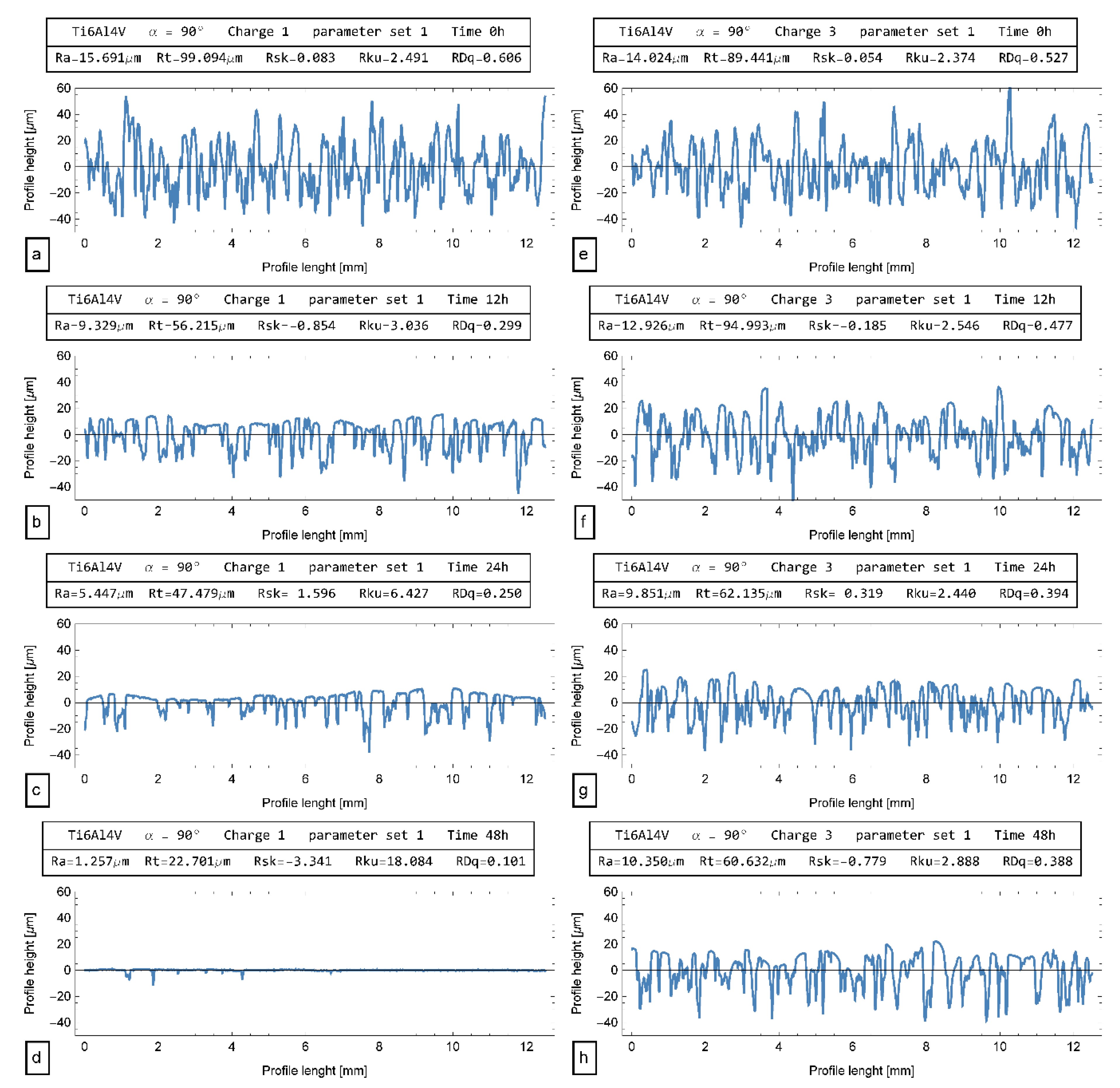
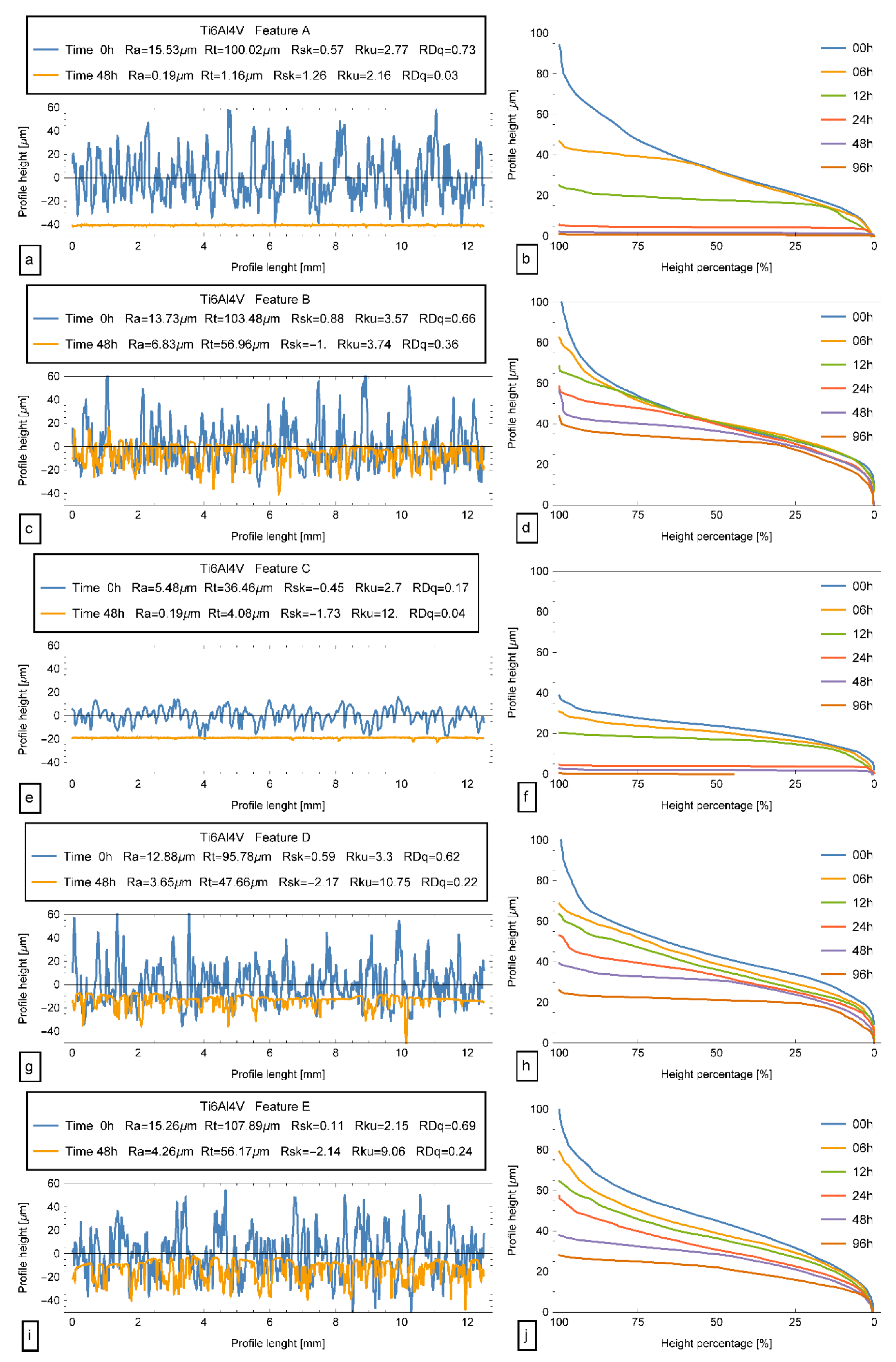
In
Figure 8a, the 0° profile is shown. The initial Ra was more than 15 µm with a peak-to-valley Rt of about 100 µm. The profile was symmetrical (the skewness was close to 0) and slightly platykurtic, since the kurtosis was near 2.5. The high value of the root-mean-square slope of the profile, i.e., RΔq, indicates a rough surface with a poor reflectivity. If charge 1 was employed and BF parameter set 1 was selected, after 12 h, the profile shown in
Figure 8b was obtained. The average roughness Ra was decreased by 41%, as well as the total roughness Rt. A cut of the peaks was observed, suggesting a good BF mechanism; in this condition, the
was about 500 and the employed motion was cascading. As a measure of the profile distribution shape, the skewness was negative, i.e., the profile was mainly made up of valleys, and the kurtosis was 3, as in a Gaussian distribution. After 24 h, the Ra was reduced by an additional 40%, the skewness was −3, and the profile was markedly leptokurtic (
Figure 8c). After 48 h, the original profile was almost deleted; only some scratches were present, probably the deepest original ones (
Figure 8d). On the other hand, the employment of charge 3 with the same BF parameters led to a marginal improvement. The original profile of this specimen (
Figure 8e) was characterized by almost the same roughness parameters; however, since, in this case, the
was 360, a marginal reduction in Ra was observed with higher peak-to-valley heights, as shown in
Figure 8f, for a processing time of 12 h. At 24 h, some differences could be observed in Ra and Rt, but the distribution shape was marginally modified. In fact, in
Figure 8g, rounded peaks can be noticed; this is an indication of improper BF surface actions where the particle energy was probably used for local plastic deformation and wear of the profile rather than micro-chipping. This led to a high processing time, as remarked by the profile obtained at 48 h (
Figure 8h), which was characterized by negligible variations of all process parameters.
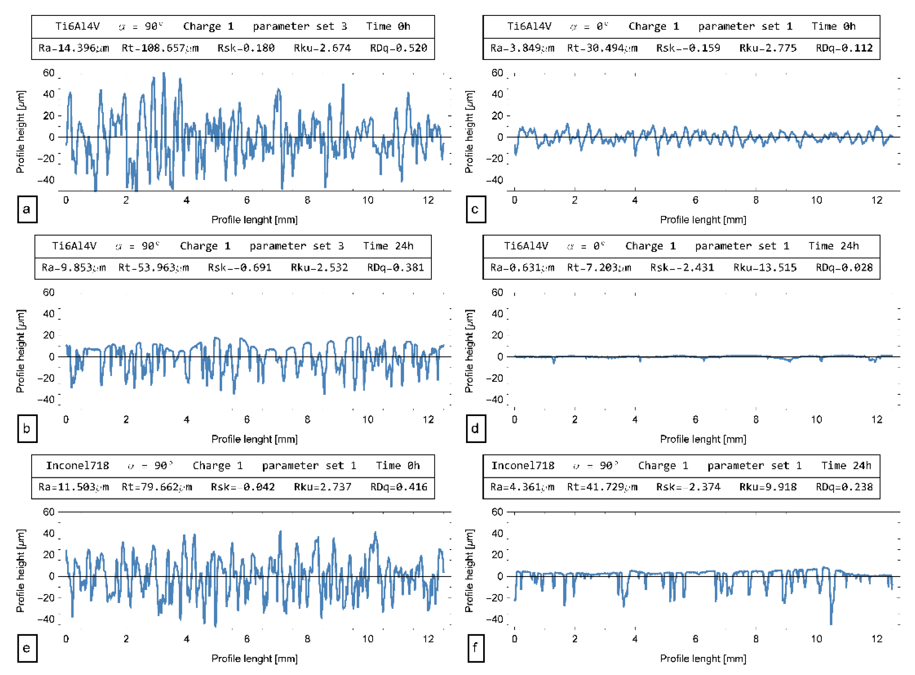
The same poor results were achieved by taking into consideration charge 1 with BF parameter set 3. Here, the
was only 250 and, after 24 h, the Ra decreased by only 32% (
Figure 9a,b). Charge 1 and BF parameter set 1 appear to be a good combination. These conditions were applied to a surface characterized by different inclinations, where different morphologies were expected. In
Figure 9c, the original profile is shown; the initial Ra was about 4 µm, the total roughness Rt was one-third of the 90° surface, and the skewness was negative. This was due to the laser scans, which were prominent, giving the profile this behavior. After 24 h, the profile (
Figure 9d) was almost deleted; the Ra was markedly reduced, and only some local valleys are observed.
When the Inconel718 material was considered, the initial Ra was lower than that of Ti6Al4V for the same surface orientation of 90° (
Figure 9e). The shape of the profile distribution was almost symmetrical and slightly platykurtic as before. The employment of charge 1 and BF parameter set 1 allowed for good improvement of Ra and Rt after 24 h. The skewness was deeply reduced, and kurtosis was highly leptokurtic, suggesting that proper BF cutting conditions took place. Upon observing the profile (
Figure 9f), this mechanism is clear since the peaks were cut away and the valleys were left unaltered. The other BF parameter sets and charges resulted in the same previous observations.
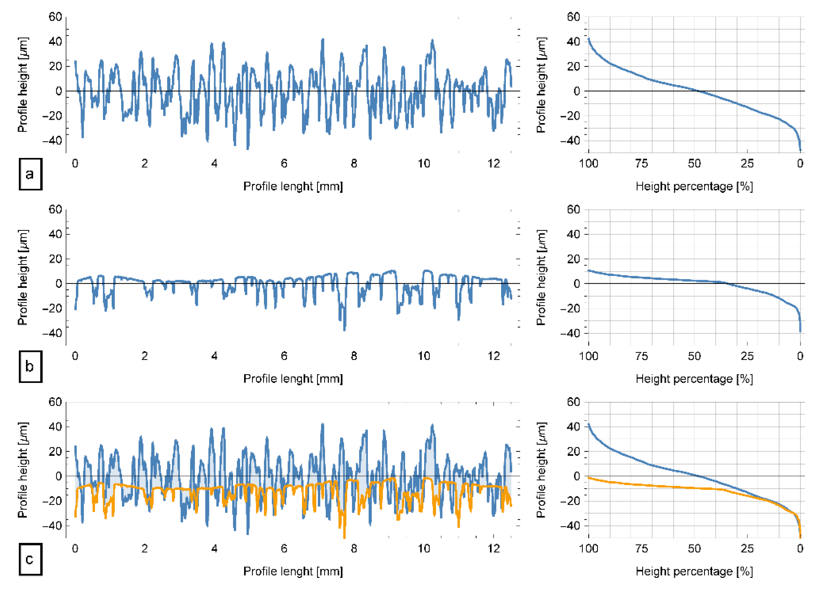
The AFC allows graphing the cumulative distribution of the profile height. In
Figure 10, this outcome is shown for the original profile (
Figure 10a) and after processing for 24 h (
Figure 10b). Under the assumption that the valley shape is not affected by the BF conditioning, the curves were aligned according to the procedure described in Reference [
35].
Figure 10c shows the outcome; approximately 20% of the curves overlapped and more than 50% were almost horizontal. This demonstrates that a mechanism of peak cutting without valley modification took place. Moreover, the area between curves represents the area removed by BF operation. The value was 15,990 µm
2/mm, equivalent to 72 µg/mm
3, corresponding to the amount of Ti6Al4V removed in 24 h.
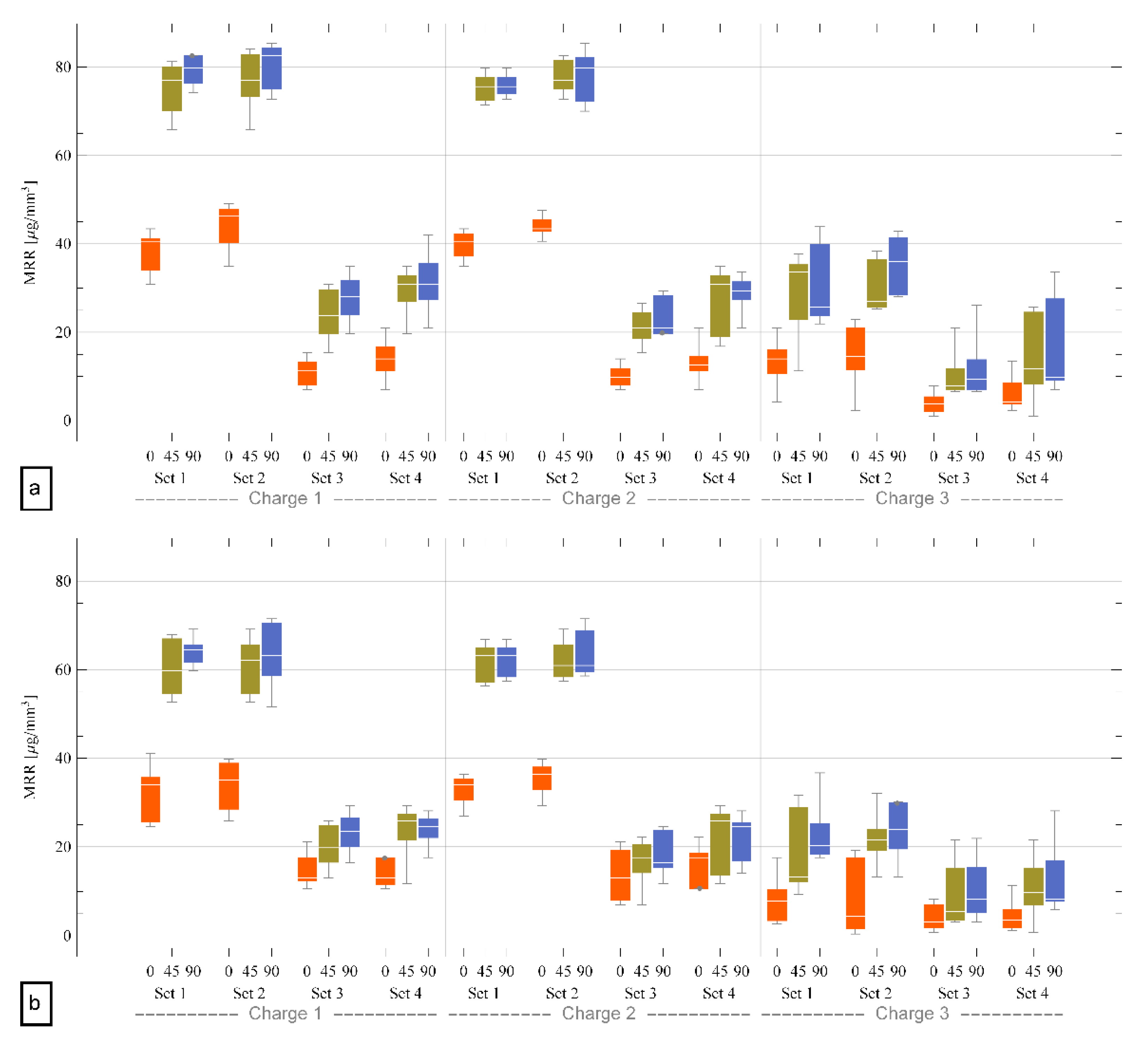
This calculation was repeated five times for each processing condition and for each charge. The overall outcome is reported in the box-and-whiskers charts in
Figure 11.
It is evident that charge 3 was characterized by a low material removal rate for all BF parameter sets. Charge 1 and 2 had similar behavior; by engaging parameter sets 3 and 4, which correspond to regimes characterized by low , the material removal rates were 40 µg/mm3 and 80 µg/mm3 for surfaces inclined at 0° and 45°/90°, respectively. Sets 1 and 2 allowed achieving the best results for these charges, and two observations can be provided. Firstly, charge 2, which was composed of mixed media, had the possibility to access small holes and, thus, it was preferred to charge 1. Secondly, set 2 was characterized by a higher filling percentage than set 1. A higher filling percentage results in greater active layer thickness; hence, big components are processed faster in relatively small barrel machines. Thus, charge 2 and BF parameter set 2 were chosen in this work.
In the case of Inconel718, the trends were very similar; charge 3 and/or small were not able to provide adequate speed; sets 1 and 2 with charges 1 and 2 allowed good performance, albeit slightly lower than the Ti6Al4V case. This was probably related to the lower initial roughness of the parts made by this material. Hence, both materials were processed by employing charge 2 and BF processing set 2.
6. Conclusions
SLM plays an important role in producing complex parts, but the obtainable surface quality remains a crucial aspect. In this work, post-processing via BF was investigated and analyzed.
In the first phase, a systematic approach based on number allowed determining the feasibility regions for BF operations. The developed BB diagrams provided the definitions of motions for different charge types as a function of the filling percentage and the rotational speed. In the second phase, the experimental activities were undertaken on simple geometries to select adequate BF process parameters and charge types for two different materials, i.e., Ti6Al4V and Inconel718. The analysis of the processed profiles demonstrated the analysis outcomes, indicating that small media are not effective for BF operation. A particular use of the AFC allowed calculating the MRR and selecting the charge and processing parameter sets. Both materials showed good machinability in the processing conditions corresponding to high number. For both materials, the mixed charge and process parameter set 2 had the desired properties, such as high MRR and good accessibility of the internal surfaces and holes. Hence, these conditions were selected for phase 3.
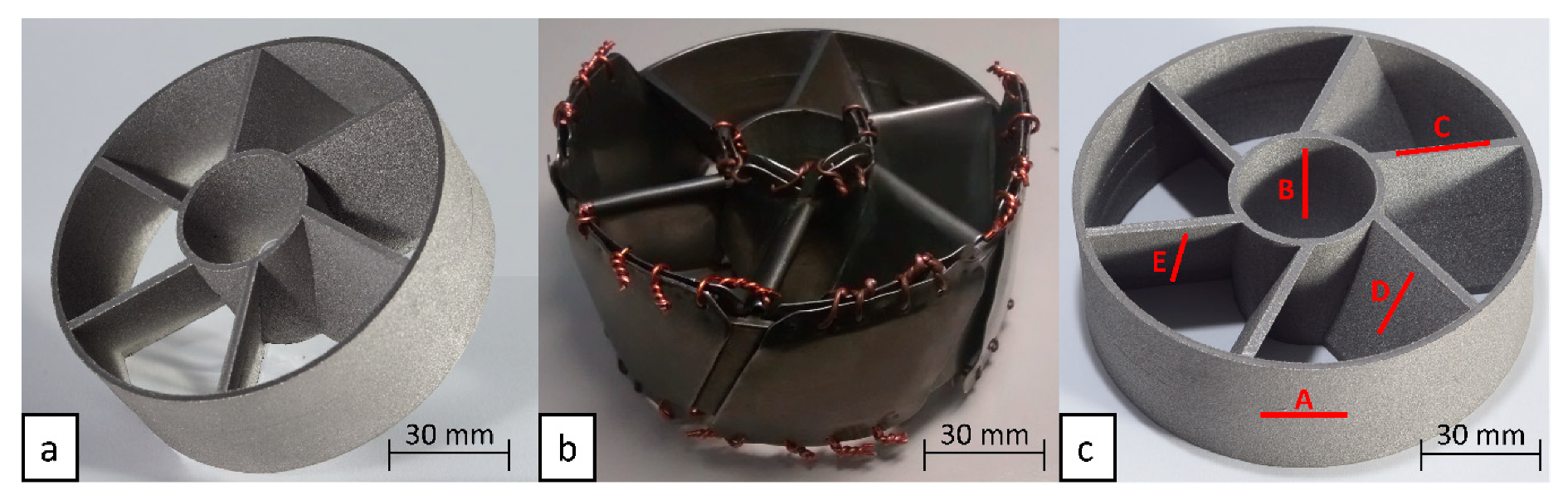
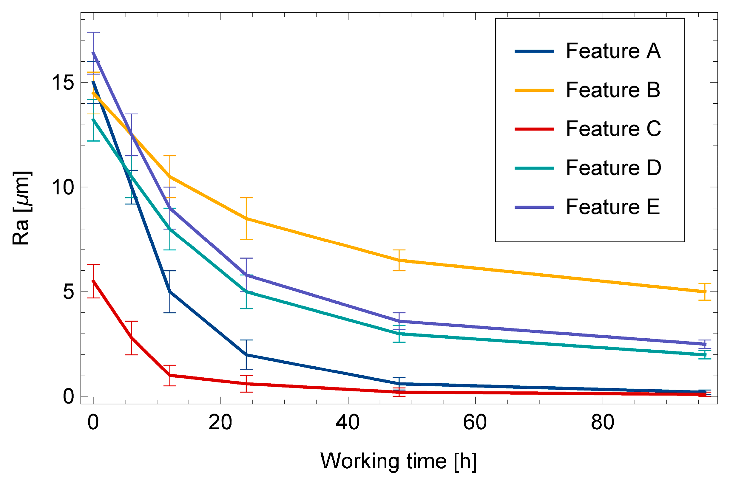
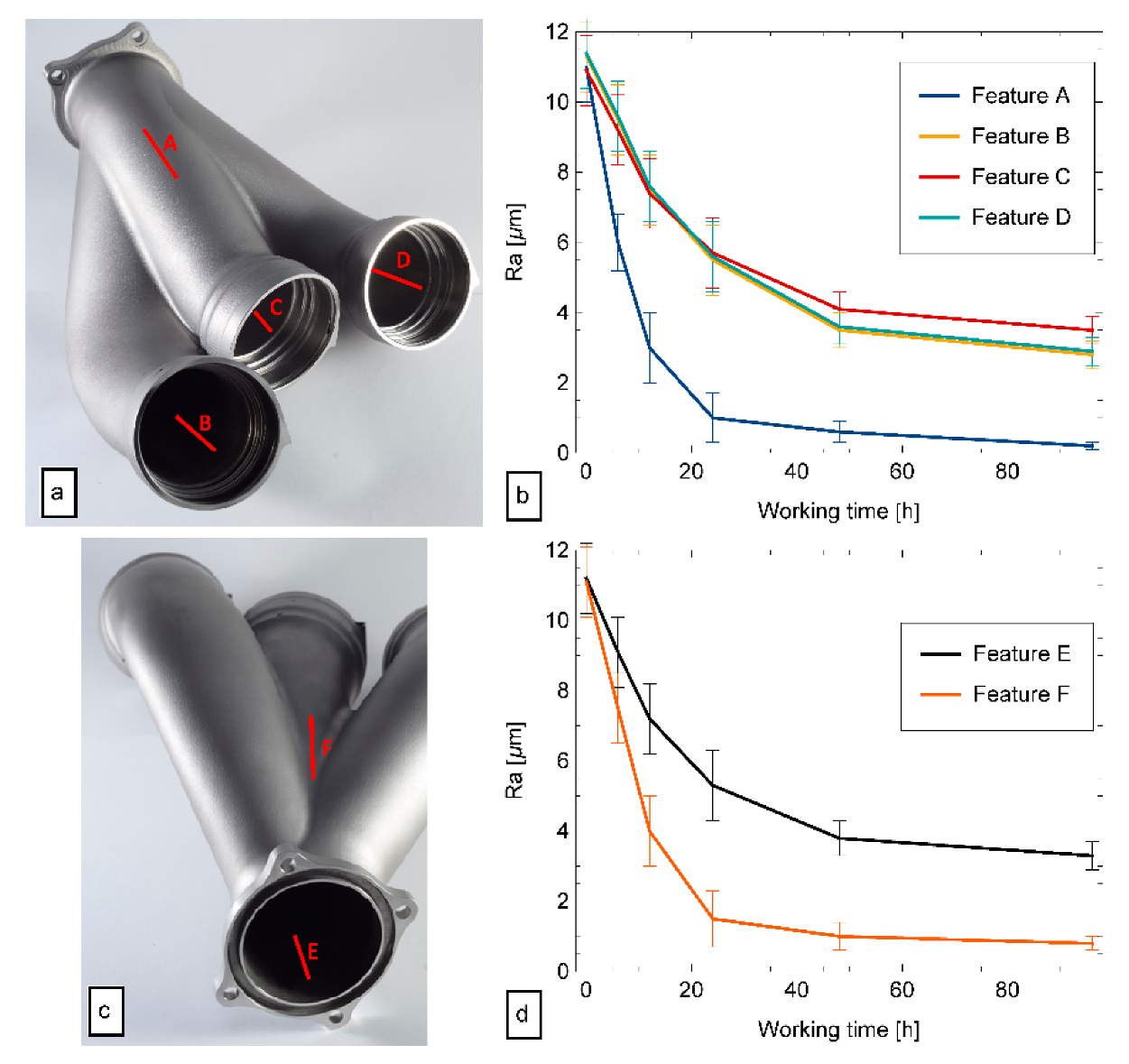
The case studies, characterized by complex geometries, confirmed the outcomes of phase 2 in term of roughness reduction for the external surfaces. Some differences were observed over the blade and the exhaust manifold internal surfaces in case studies 1 and 2, respectively. For the former, the reduced space for the media motion determined a slower BF action as per a low number; moreover, the difference in roughness reduction was detected for the blade’s up-facing and down-facing surfaces due to the different SLM original morphologies. For the latter, the angled internal surfaces were subjected to different BF conditioning within the active layer flow; in this case, the limited media accessibility was also reflected in a slower finishing process.
Apparently, the long processing time remains a limitation for BF employment on SLM parts. However, it must be considered that, in industrial use, the time is typically optimized by using large BF machines which have a thick active layer; consequently, a bigger surface area is processed at the same time, and many parts can also be processed together.


