Article

Framework and Application of a Big Data Monitoring System for Mining with a Pillar-Free Self-Forming Roadway

1
State Key Laboratory for Geomechanics & Deep Underground Engineering, China University of Mining & Technology (Beijing), Beijing 100083, China
2
School of Mechanics and Civil Engineering, China University of Mining & Technology (Beijing), Beijing 100083, China
*
Authors to whom correspondence should be addressed.
Appl. Sci. 2019, 9(10), 2111; https://doi.org/10.3390/app9102111
Submission received: 4 April 2019 / Revised: 15 May 2019 / Accepted: 20 May 2019 / Published: 23 May 2019
(This article belongs to the Special Issue Recent Progress in Fiber Optic Sensors: Bringing Light to Measurement)

Abstract

:
The construction of a self-formed roadway without coal pillars is a new mining technology based on short-arm beam formation through roof cutting. With it, mining, tunneling and retaining roadway construction can be accomplished in a ‘three-in-one’ process that removes the need to dig in advance at the working face and to leave behind coal pillars. In order to realize real-time monitoring and warnings regarding rock pressure during this process, a big data monitoring system was developed based on quasi-distributed fiber Bragg grating (FBG) sensing technology and cloud technology. Firstly, real-time monitoring data on the stress and strain of the underground surrounding rock-support system are obtained by FBG sensor and transmitted to the main computer of the above-ground monitoring and early warning system by using an underground industrial ring network. These data are then sent to a big data remote online real-time monitoring system. Through the deployment of a cloud server, authorized users can observe changes in force and movement in the rock surrounding the supporting system during coal mining and roadway formation from anywhere and at any time. The successful application of the system in the S1201-II working face of the Ning Tiaota Mine shows that this remote real-time monitoring system can enable timely and accurate field data acquisition, feedback real-time production information and achieve good monitoring performance. This study thus provides a scientific basis for ensuring safe mining with the coal pillar-free self-forming roadway method.

1. Introduction

Longwall mining that leaves coal pillars in the remaining section is currently the most commonly used coal mining method. Continuous research by coal scientists and technicians all over the world has refined this mining method until it is a relatively perfect theoretical and technical system. However, because this method necessitates the excavation of the roadway in advance at both ends of the face and due to the requirements of coal pillar bearing capacity and roadway stability, a certain width must be set in the mining process [1,2]. This means that a huge amount of roadway excavation engineering must be carried out, constituting a serious waste of resources [3,4,5]. The technology for establishing a gob-side retaining roadway without coal pillars has enabled a halving of the driving capacity of mining roadways in the working face and a great improvement in the resource recovery rate. However, that technology often relies on a high-strength roadside filling body to maintain the original mining roadway, requiring the use of a complex filling system and filling technology, thereby limiting its promotion and application [6,7,8,9,10]. In view of the above problems, the team of He Manchao put forward a method for constructing a self-made roadway without the use of coal pillars based on the theory of forming a short-arm beam through roof cutting. This type of mining roadway is formed automatically while mining and is reserved for continued use for the next working face, turning mining, tunneling and retaining roadway construction into a ‘three-in-one’ process and obviating the need for advance excavation of mining roadways and roadway-protecting coal pillars between working faces [11]. Good results have been obtained in field tests to determine the best cutting height and support width where the deformation of the roof is controlled by a short cantilever beam [12]. The supporting technology of a constant resistance, large deformation anchor cable has been developed, which has been shown to achieve low deformation of the roadway and a remarkable control effect [13]. The proposal of this method to automatically make a roadway without coal pillars has ended the phase in the history of coal mining in which roadways must be excavated before coal mining. This is a major change in coal mining technology and one of the important developments in the sustainable mining of coal resources.
A large number of high-tech monitoring technologies have been applied in practical engineering contexts to meet requirements as to engineering quality and the safety of personnel and equipment. For example, in earthquake monitoring, cloud computing information services enable more rapid algorithmic seismic data processing [14] and using Voronoi technology and cloud services greatly improves the accuracy of seismic activity calculations [15]. In slope monitoring, the development of a mechanical calculation model of stratal structure and its combination with a monitoring system allows areas that pose a high inclined rock burst hazard to be identified and stratum ruptures and movements to be monitored [16]. In coal gasification monitoring, acoustic emission monitoring plays an important role in site safety and can effectively reduce underground coal gasification (UCG) risk [17]. Furthermore, the combined use of a wireless sensor network and a coal mine safety monitoring system has been shown to be an effective measure to eliminate the hidden danger of gas accidents. Its ability to acquire a large amount of data, high accuracy and low environmental impact make it far superior to traditional gas sensing systems [18]. In roof monitoring, a sensor network using wireless communication has been used to monitor the health of the underground pillar roof in real time and to predict roof fall [19]. A wide variety of mine pressure monitoring equipment such as three-dimensional laser roadway displacement monitoring [20] is also used in coal mining, utilizing three-dimensional modeling, RFID/INC (Radio Frequency Identification) integrated positioning systems and other advanced systems that enable the real-time understanding of the underground orebody [21]. The newly developed technology of a wireless mine security information system can save space and ensure the safe mining of coal [22]. This involves the use of a wireless sensor network and associated communication technology supported by a cloud network for coal mine safety monitoring, enabling automatic processing of underground data and transmission to wells. Such a system offers high accuracy and good stability and is considered to be the future direction of coal mine safety inspection [23,24,25]. In addition, the installation of a breaker line support (BLS) monitoring system in Laleham 1 Coal Mine and the real-time transmission of data above-ground have been shown to be beneficial for promoting mechanized pillar mining operations [26]. Xu Wenquan et al. developed a mining stress monitoring sensor and applied it in the field at the Liangbei coal mine [27]. Wang Enyuan et al. developed and applied a three-way cylinder pressure sensor and a dynamic monitoring system for coal and rock mass stress that was able to determine the distribution and the evolution law of stope stress [28]. Ou Pingyang has discussed a data integration technology for coal mine safety monitoring systems [29], whereas Liu Zenghui et al. have established a dynamic monitoring system for surrounding rock deformation based on distributed optical fiber sensing technology [30]. Du Jingjing [31], Tang Shucheng [32] and others have also conducted relevant research and achieved useful results.
A distributed fiber Bragg grating (FBG) sensor can provide more accurate and reliable strain measurement data in underground mines than can traditional monitoring equipment [33]. Such sensors are also highly sensitive to the vital signs of rescuers and can meet the needs of emergency rescue [34]. This technology is now widely used in geotechnical engineering structures, where it enables real-time monitoring of overall structural health and offers major practical benefits [35,36,37,38,39,40]. This paper applies FBG sensing technology to the new coal pillar-free mining method. A big data remote online real-time data monitoring system is designed and established that integrates multi-source information publishing and monitoring technology via the cloud server ECS (Elastic Compute Service), cloud database RDS (Relational Database Service) and cloud website technologies. This approach can improve the intelligence, adaptability, security and stability of the whole monitoring system and realize the mine pressure-monitoring and early warning target ‘find quickly, control well, sort out early, resolve well.’

2. Technical Principles of the Coal Pillar-Free Self-Formed Roadway Construction Method

2.1. Overall Layout of the Working Face

As shown in Figure 1a, a boundary roadway is first established along the perimeter of the disc area to form a ventilation and transportation system in which the lower boundary roadway is used as the inlet air roadway of the first mining face, the upper boundary roadways are the return air roadways of the disc area and the right boundary roadways are the opening and cutting holes for the disc area. Except for the last mining face, a return air lane for the working face is formed automatically as mining activity proceeds and this lane is retained as the air entry lane of the next working face, as shown in Figure 1b. As a result, except for the boundary roadway, there is no need to advance the excavation of the face into an entirely new part of the disc area and there is no need to leave behind coal pillars to protect roadways between the working faces.

2.2. Roadway Formation Principle

The shearer will form a space at its tail after the coal body has been mined. Once the space has been formed, the roof will be supported by a high-strength anchor cable at a precalculated position and the roof will be cut. At the same time as the next coal mining step is pushed forward in the working face, a high-strength vertical support structure is set up behind the working face to support the roof of the supporting space temporarily and a gravel protection structure is installed to prevent gangue in the goaf from entering the supporting space, as shown in Figure 2. The above processes, comprising coal mining, anchor-cable support, roof jointing, temporary support, gravel protection and so forth, work in parallel with the forward movement of the hydraulic support. Because the roof is sliced, the mechanical connection between the roof of the supporting space and the roof of the goaf is weakened. After the hydraulic support has moved forward, the roof of the goaf will quickly collapse and fill the goaf. When caving in the caving zone has been completed, the gangue in the goaf will support the overlying strata and will be gradually compacted under their load. When the working face has been pushed forward a certain distance and monitoring data shows that the rock surrounding the support space has begun to stabilize, the temporary roof support structure is removed and the support space forms a stable roadway. The roof and floor of the roadway and one of its sides are cut out by the shearer and the other side is formed by the stacks of goaf gangue.
Thus, this method achieves the goal of Pillarless Mining without advance excavation of a mining roadway by combining coal mining, tunneling and retaining roadway construction in a “three-in-one” process.

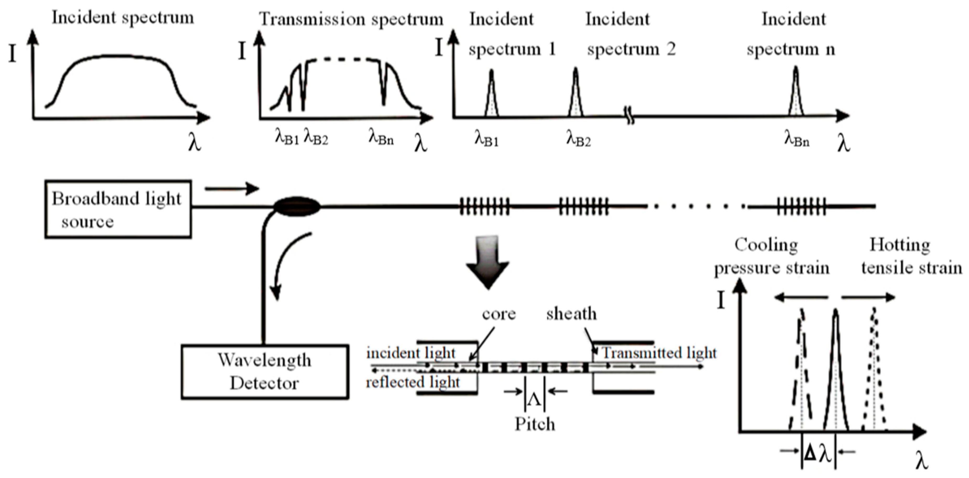
3. Principle of Fiber Bragg Grating Sensing Technology

Quasi-distributed fiber Bragg grating (FBG) sensing technology is used as the sensor equipment for a big data monitoring system for coal pillar-free longwall mining. Fiber grating strain gauges encapsulated in many different types of fiber grating sensors are placed on objects so as to measure certain parameters of those objects. When the temperature, stress or strain of the measured object changes, the fiber experiences axial strain, which enlarges the grating period and reduces the radius of the fiber core and cladding. The photoelastic effect causes the refractive index of the fiber to change, which results in a wavelength shift of the grating. The measured parameters can then be calculated based on the linear relationship between strain and the wavelength offset of the grating. The principle of FBG sensing is shown in Figure 3.
An FBG is formed by along-axis periodic change in the refractive index of the fiber core. When the incident laser wavelength and the period of the FBG satisfy Formula (1), the grating will reflect the laser.
λ B = 2 n e f f Λ
In the formula, λ B is the wavelength, n e f f is the effective index of refraction and Λ is the grating spacing.
Formula (1) shows that the reflected wavelength of FBG is related to the grid spacing and the refractive index of the optical fiber. When the optical fiber is deformed axially, the grid spacing and the refractive index will drift and the reflected wavelength will drift accordingly. The amount of deformation of the optical fiber can be obtained by measuring the amount of drift. The experimental results show that strain and temperature have a good linear relationship with the central wavelength and are independent of each other. The correlation formula is shown in Formula (2).
Δ λ B = α ε ε + α T Δ T
In the formula, α ε is the strain sensitivity coefficient of the fiber grating, α T is the temperature sensitivity coefficient of the fiber grating, Δ T is the change in temperature value and ε is the strain.
Because an FBG can accurately measure the micro-deformation of materials, FBGs have been packaged and attached to elastic components such as pressure, displacement and temperature sensors to achieve multi-variable sensor testing.
Incorporating optical fiber information acquisition and transmission into the sensor equipment of the monitoring system for a coal pillar-free self-made roadway offers the following unique advantages:
(1) Non-live line working is intrinsically safe and suitable for the flammable and explosive environment in an underground coal mine.
(2) Optical fiber transmission suffers little loss over long distances, is not affected by electromagnetic field interference, temperature and humidity and has high transmission reliability.
(3) The optical fiber sensor monitoring system has a large capacity, is simple and easy to maintain and makes multi-point and multi-parameter online monitoring easy, greatly reducing the variety and quantity of equipment required.
(4) Optical fiber sensors make it easy to realize multi-point distributed measurement and long-term online pressure monitoring.

4. Monitoring System Framework

4.1. Components of the Multi-Source Monitoring System

4.1.1. Force Monitoring on Constant-Resistance Large-Deformation Anchor Cables

In order to ensure that the supporting structure has sufficient supportive strength and adapts to dynamic pressure in the rock surrounding the roadway, the roof formed under the pillar-free self-formed roadway method is supported by a cable that utilizes the effect of a negative Poisson’s ratio (an NPR cable, Figure 4). The NPR type is shown in Table 1 below. When the forces on the anchor cable are less than the constant resistance value, the anchor cable is in an elastic working state. When the anchor cable experiences instantaneous dynamic pressure, it will be stressed. When the pressure is greater than the constant resistance value, the constant resistance device will absorb energy by generating slip deformation, ensuring that the anchor cable does not break and continues to play its bearing role.
During support by the NPR cable, the stress state is sensed by an FBG anchor cable stress sensor as shown in Figure 5. And its specific parameter models are shown in the Table 2. The basic principle of this sensor is that a high-stability and high-sensitivity strain fiber grating is placed within a steel pressure cylinder. When the load causes axial deformation of the steel cylinder, the fiber grating deforms along with it and the stress change causes a change in the reflection wavelength of the fiber grating. The system is set to measure the data of the fiber Bragg grating anchor cable force sensor every 1 min. The measured data can be read by the fiber Bragg grating demodulator to obtain the wavelength reading that causes the deformation of the steel cylinder and then the load value of FBG anchor cable force sensor can be calculated by substituting calibration coefficient.

4.1.2. Roof and Floor Proximity Monitoring

FBG displacement sensors like that shown in Figure 6 are used to detect the roof and floor proximity of the self-made roadway and its specific parameter models are shown in the Table 3.
The FBG displacement sensor uses an isosceles cantilever beam structure. Two FBGs with different central wavelengths are arranged on the strain beam to monitor the relative displacement of the top and bottom plates. The internal structure of the sensor is shown in Figure 7. When the distance between the fixing ring of the wire rope and the main body of the sensor increases, the wire rope causes the winding wheel to rotate; the winding wheel causes the precision screw to rotate, energy is stored in the scroll spring, the precision screw moves in the direction of the strain beam and the flexural strain of the strain beam increases. The measured displacement is obtained by a calibration formula relating displacement to flexural strain. When the distance between the fixing ring of the wire rope and the main body of the sensor becomes small, the winding wheel rotates under the elastic force of the scroll spring, the wire rope is coiled onto the winding wheel, the precision screw moves to the far side of the strain beam and the flexural strain of the strain beam decreases. The measured displacement is again obtained by the displacement–flexural strain calibration formula. The displacement will be measured once a day.

4.1.3. Roof Separation Monitoring

An FBG layer-separation sensor as shown in Figure 8 is used to detect roof separation and its specific parameter models are shown in the Table 4.
The FBG separation layer sensor is similar to the FBG top displacement sensor in principle. An FBG is bonded to both sides of two strain beams to detect displacement changes. The two ends of the sensor tension spring are respectively fixed on the upper part of the spring pull rod and the precision screw rail and is used to tighten the precision screw rail and cause the precision screw to slide reciprocally inside the precision guide rail; the precision screw rail is fixed with the winding coil and when the displacement of the wire rope connected with the external anchor claw changes, the wire rope pulls the winding coil to cause the precision screw rail to slide, resulting in deformation of the strain beam. This changes the central wavelength of the FBG. The layer separation sensor will measure the data once a day and the measured data will be demodulated by the fiber Bragg grating demodulator to obtain the layer separation change.

4.1.4. Pressure Monitoring of Cut Top Support

A new type of hydraulic support with high initial supporting force and high working resistance is used to temporarily strengthen the roof under this coal mining method. The pressure on the support is sensed by the FBG hydraulic sensor shown in Figure 9 and its specific parameter models are shown in the Table 5. It gets a data in a minute.
This hydraulic sensor adopts the cylindrical thin-wall sensing principle. According to generalized Hooke’s law and the strain characteristics of an FBG, it can be stated that:
Δ λ B = 0.39 d λ B E h ( 1 1 2 μ ) p
In the formula, E is the elastic modulus of the material, h is the thickness of the thin wall, d is the inner diameter of the cylinder, p is the pressure and μ is the Poisson’s ratio of the optical fiber.
There is a linear relationship between the drift of the center wavelength of the grating and the measured pressure. The range of pressure measurement can be changed by adjusting the inner diameter of the cylinder and the wall thickness. The principle is shown in Figure 10.

4.1.5. Monitoring of the Sideways Pressure of Crushed Stone

In the pillar-free self-formed roadway mining method, one of the sides of the automatically formed roadway is formed by a stack by goaf collapse gangue, which will produce lateral extrusion force on its lateral protective structure while in a loose state. The lateral pressure from the gravel is measured by the FBG lateral pressure sensor illustrated in Figure 11. It measures 30 data in a second.
The FBG lateral pressure sensor is a high-strength heat-treated steel cylinder. Its working principle is that one end of the sensor is fixed, the other end is connected to an elastic pressure-sensitive diaphragm and a highly stable and sensitive FBG is installed on the diaphragm. When the load causes axial deformation of the elastic sensing diaphragm, the fiber grating will deform synchronously, and its reflection wavelength will be changed. The wavelength reading of the elastic pressure-sensitive diaphragm can be measured by FBG demodulator and the load value can be calculated through the use of a calibration coefficient. The FBG lateral pressure sensor has many advantages including high resolution, strong anti-jamming performance, sensitive response to concentrated loads and reliable measured values.

4.1.6. Principle of Demodulation Technology Based on Tunable Filter of FGB

There are many kinds of FBG demodulation technologies. The system adopts tunable filter method. It is to monitor the reflection spectrum of FBG in real time and detect the wavelength drift. Various optical filters are used in the demodulation process. The output is the convolution of FBG output spectrum and filter wave function. When the spectrum of FBG output coincides with that of attuned filter, the maximum value is 1, which makes the narrow band signal light of specified band pass through and restrains the output of other band signal wavers. By measuring the maximum point and the corresponding wavelength change of the attuned filter, the wavelength drift of FGB can be calculated.

4.2. Overall Framework of the Monitoring System

As the working face is advanced, FBG stress sensors, displacement sensors, roof separation sensors, hydraulic sensors and lateral pressure sensors are installed in the roadway every 50 m. The monitoring data are transmitted through the communication cable to a switch on the communication vehicle at the other end of the working face by an Ant Fiber Bragg Grating Demodulator, which transmits the data through an industrial ring network to the main machine on the well. Users in the mining area can access the data through the industrial ring network. In addition, open secure ports are available through an industrial ring server for internal and external network port mapping. Finally, the big data generated by the coal-free self-forming roadway construction method is deployed and released on the internet through the use of a cloud server. The schematic diagram of the system is shown in Figure 12.

4.3. Cloud Service System Construction

4.3.1. Cloud Service Platform

The cloud service platform of the coal pillar-free self-forming roadway big data monitoring system can be divided into three tiers: a data layer, application layer and client layer. The framework and system functions of each layer are shown in Table 6.

4.3.2. Cloud Server

With the advent of cloud computing and big data, traditional data servers will gradually be replaced by cloud computing data centers. The Elastic Compute Cloud Service (ECS) is used in the monitoring system outlined in this paper. A cloud server has the following remarkable advantages over traditional data servers:
(1) Stability: The disk data reliability of cloud servers reaches 99.9% and automatic snapshot backup and data recovery are convenient and fast, while traditional servers are limited by their hardware configurations, are affected by computer room conditions and require manual backup and difficult and time-consuming manual data recovery.
(2) Flexibility: It is possible to freely configure the CPU, memory and bandwidth of Cloud servers and upgrade their configuration at any time to ensure that data is not lost. Traditional servers have a fixed configuration and, if hardware upgrade is required for configuration modification, it will take a long time to implement and service downtime is inevitable.
(3) Security: Cloud servers have DDoS protection and incorporate security measures such as trojan horse removal to ensure the safety and reliability of monitoring data, while traditional servers need to purchase and deploy additional security measures.
(4) Scalability: Cloud servers can seamlessly connect with a wide variety of cloud products that can sustainably provide complete computing, storage, security and other solutions for system applications, while traditional servers cannot guarantee the scalability of data growth and sustainability.

4.3.3. Cloud Database

The RDS (Relational Database Service) is a professional, high-performance, stable, reliable and flexible scalable online cloud database service. It provides a web interface for configuration, data backup and recovery, security management, monitoring and expansion functions. The big data monitoring system adopts the MySQL version of this cloud database.

4.3.4. Cloud Service Web Platform

The interface of the real-time monitoring system is hosted on a cloud server and is shown in Figure 13. The system was developed using JSP programming and background management system of the website takes a human-focused approach to web management. This interface is convenient for carrying out monitoring functions and adding and deleting monitoring points in the mining project and facilitates timely updating and adjustment of front-end monitoring content.
The web platform has the following functionality:
(1) Taking a mine roadway simulation map as the background, the positions of the measuring points and sub-stations are indicated by graphics and real-time information from each monitoring point is displayed visually. The graphics can be scaled and moved conveniently and sub-station and the point statuses are refreshed in real time.
(2) Comprehensive data display, including curves, column charts and reports.
(3) Data query functions including daily, monthly and so forth.
(4) Over-limit alarm function.
(5) Information editing and monitoring system equipment management.

4.3.5. Information Publishing System

The monitoring system has an information publishing system formed of three main parts: a central control system, a network cloud platform and a terminal display system. The central control system is installed on the management and control server. Its main function modules are data management, analysis management, terminal management and user management. By receiving, analyzing, publishing and monitoring the monitoring data and it can manage and control all the function modules in a unified way. The network cloud platform is the information transfer bridge between the central control system and the terminal display system. Accessing the database through a cloud platform is more secure and reliable than traditional way. The terminal display system includes a media player, video-audio transmitter, video-audio repeater and display terminal. The system issues the field data transmitted by the cloud server, analyzes and generates pressure–time curves automatically, judges the safety and stability state of the monitoring site roadway in real time and automatically sends out early warning signals.

5. Field Application

5.1. Engineering Survey

The S1201-II experimental working face of Ning Tiaota Coal Mine is the first implementation of the pillar-free self-formed roadway construction method. Its inclined length is 280 m, its strike length is 2344 m, the average coal seam thickness is 4.11 m, the burial depth is 90–165 m, the coal seam occurrence is continuous and the coal seam dip angle is 0–2°. It adopts the method of one-time full-height mining, longwall retreat mining, comprehensive mechanized mining and the all-caving method to manage the roof. According to drilling data from near the working face, the roof of this working face is dominated by sandstone and the average strength index of the rock strata is 23 MPa. The basic top is medium-grained sandstone with massive bedding and localized sandy mudstone, 5.4–21.5 m thick. The direct top is thin siltstone and sandy mudstone layers with horizontal bedding; the former is 0.78–4.05 m thick and the latter is about 4 m thick. The direct bottom is a thin layer of siltstone with a thickness of 1.8 to 16.3 m and a thin layer of fine-grained sandstone. The hard floor is fine-grained sandstone 3.2–19.6 m thick.
The layout of the test working face is shown in Figure 14. Because it is the first test working face to use the pillar-free self-formed roadway method, a rubber transport channel under the working face had been excavated in advance. Therefore, auxiliary haulage along the upper part of the working face will be mined, excavated and retained along with it. The design dimensions of the crossheading are 6.2 m wide and 3.8 m high. The test mine is a low gas mine. After adopting the new mining method, the “Z”-type ventilation mode is adopted for the working face; the air flow route is shown in Figure 14.
In order to study the mine pressure and its manifestation in the test working face, the mine pressure of the automatically formed roadway is monitored using the big data remote online real-time monitoring system outlined in Section 4. Whenever the working face has advanced a certain distance, the corresponding FBGs are installed in the roadway area behind the working face and connected to the industrial ring network. The layout of the stations is shown in Figure 15.

5.2. Monitoring Data

Typical monitoring curves obtained by some of these sensors during working face propulsion are shown in Figure 16, Figure 17 and Figure 18. The NPR stress monitoring curve in Figure 16 shows that the force on the constant-resistance large-deformation anchor cable increased several times in the course of advance along the working face. On the basis of the installation position of the sensor, the timing of stress changes and the position of the working face at those times, force change on the anchor cable can be attributed to the initial pressure of the roof and the periodic pressure of the working face. When the working face has been pushed forward a certain distance, the force in anchor cable becomes basically stable.
The separation monitoring curve in Figure 17 shows that both the deep base point—which is fixed in the stable rock stratum at 5 m deep of the borehole—and the shallow base point—which is fixed at 2–2.5 m of the drill hole—tend to give constant separation values after a slow rise. The separation value of the shallow base point is about 14 mm and that of the deep base point is about 33 mm. When the roof is fitted with a dense, constant resistance 10.5-m-long anchor rope after the formation of the roadway and considerable pre-tightening force is applied, the roof experiences a certain degree of elastic compression. As time goes on, this elastic compression is bound to rebound in part or altogether. Therefore, the data measured by the separation sensor is not the actual roof separation and there may be springback deformation of the roof.
The monitoring curve of roadway roof and floor proximity in Figure 18 shows that it increases gradually in the roadway area after the working face has been pushed forward. When the working face is pushed forward a certain distance, the monitoring curve tends to level out, indicating that the rock surrounding the roadway becomes basically stable at this time, with no significant increase in proximity between the roof and floor of the roadway.
The monitoring curves shown in Figure 16, Figure 17 and Figure 18 can be displayed in the terminal display system to reflect activity in the rock surrounding the roadway at the construction site in real time. The monitoring system will automatically sound an alarm when the stress monitoring curve of the anchor cable begins to increase suddenly, and the increment exceeds 350 kN. It indicates that the roadway will be in an unstable state. At this time, the supporting form or strength of the roadway can be optimized and adjusted immediately, or emergency measures can be taken to evacuate workers from the working face to ensure the safety of mining, roadway formation and roadway retention.

6. Conclusions

Based on quasi-distributed fiber Bragg grating (FBG) sensing technology and cloud technology, a remote online real-time monitoring system was established for large volumes of rock pressure data generated during application of the coal pillar-free self-formed roadway construction method.
(1) The system transfers field monitoring data obtained by FBG sensors from an industrial ring network to the host computer of the above-ground monitoring system and publishes the data on a cloud-hosted web platform, realizing real-time online monitoring and early warnings on the basis of multi-parameter data, such as the force on constant-resistance large-deformation anchor cables, separation in the top layer, relative movements of the top and bottom plate, pressure on the top-cut protection support bracket and lateral pressure from gravel in the lane-formation area.
(2) Field application proves that this big data remote online real-time monitoring system can acquire timely and accurate field data and feed back field production information in real time, achieving good monitoring results. This provides a scientific basis for safe mining with the coal pillar-free self-formed roadway method.
(3) Because cloud servers are superior to traditional servers in many ways such as in elasticity, ease of expansion, stability and security, this big data monitoring system based on cloud servers provides a new technological means of monitoring mine safety and has very good application value.

Author Contributions

Conceptualization, Z.T. and H.Z.; methodology, Z.T.; software, H.Z.; formal analysis, X.Z. (Xiaohui Zheng); data curation, H.Z.; writing—original draft preparation, X.Z. (Xiulian Zhang); writing—review and editing, C.Z.; and X.Z. (Xiulian Zhang).

Funding

This research was funded by the Key Research and Development Project of Zhejiang Province, grant number 2019C03104”.

Acknowledgments

This work was supported by the Key Research and Development Project of Zhejiang Province (Grant No: 2019C03104).

Conflicts of Interest

The funders had no role in the design of the study; in the collection, analyses or interpretation of data; in the writing of the manuscript or in the decision to publish the results.

References

  1. Wang, Q.; Gao, H.K.; Jiang, B.; Li, S.C.; He, M.C.; Wang, D.C.; Lu, W.; Qin, Q.; Gao, S.; Yu, H.C. Research on reasonable coal pillar width of roadway driven along goaf in deep mine. Arab. J. Geosci. 2017, 10, 466. [Google Scholar] [CrossRef]
  2. Zhang, S.C.; Li, Y.Y.; Shen, B.T. Effective evaluation of pressure relief drilling for reducing rock bursts and its application in underground coal mines. Int. J. Rock Mech. Min. Sci. 2019, 114, 7–16. [Google Scholar] [CrossRef]
  3. He, M.C.; Chen, S.Y.; Guo, Z.B.; Yang, J.; Gao, Y. Controal of surrounding rock structure for gob-side entry retaining by cutting roof to release pressure and its engineering application. J. China Univ. Min. Technol. 2017, 46, 959–969. [Google Scholar]
  4. Guo, Z.B.; Wang, J.; Cao, T.P.; Chen, L.; Wang, J. Research on key parameters of gob-side entry retaining automatically formed by roof cutting and pressure release in thin coal seam mining. J. China Univ. Min. Technol. 2016, 45, 879–885. [Google Scholar]
  5. Sun, X.M.; Liu, X.; Liang, G.F.; Wang, D. Key parameters of gob-side entry retaining formed by roof cut and pressure releasing in thin coal seams. Chin. J. Rock Mech. Eng. 2014, 33, 1449–1456. [Google Scholar]
  6. Jia, M.; Xu, Y.; Jiang, X.Y.; Bai, J.B. Technology of gob-side entry retaining with advance standing props. J. Min. Saf. Eng. 2017, 34, 228–234. [Google Scholar]
  7. Huang, W.P.; Li, C.; Zhang, L.W. In situ identification of water-permeable fractured zone in overlying composite strata. Int. J. Rock Mech. Min. Sci. 2018, 105, 85–97. [Google Scholar] [CrossRef]
  8. Li, Y.; Zhang, S.; Zhang, X. Classification and fractal characteristics of coal rock fragments under uniaxial cyclic loading conditions. Arab. J. Geosci. 2018, 11, 201. [Google Scholar] [CrossRef]
  9. Zhang, Z.Z.; Bai, J.B.; Chen, Y.; Yan, S. An innovative approach for gob-side entry retaining in highly gassy fully-mechanized longwall top-coal caving. Int. J. Rock Mech. Min. Sci. 2015, 80, 1–11. [Google Scholar] [CrossRef]
  10. Luan, H.J.; Jiang, Y.J.; Lin, H.L.; Li, G.F. Development of a new gob-side entry-retaining approach and its application. Sustainability 2018, 10, 470. [Google Scholar] [CrossRef]
  11. He, M.C.; Wan, Y.J.; Yang, J.; Zhou, P.; Gao, Q.; Gao, Y.B. Comparative analysis on stress field distributions in roof cutting non-pillar mining method and conventional mining method. J. China Coal Soc. 2018, 43, 626–637. [Google Scholar]
  12. Wang, Y.J.; Gao, Y.B.; Wang, E.Y.; He, M.C.; Yang, J. Roof deformation characteristics and preventive techniques using a novel non-pillar mining method of gob-side entry retaining by roof cutting. Energies 2018, 11, 627. [Google Scholar] [CrossRef]
  13. Wang, Q.; He, M.C.; Yang, J.; Gao, H.K.; Jiang, B.; Yu, H.C. Study of a no-pillar mining technique with automatically formed gob-side entry retaining for longwall mining in coal mines. Int. J. Rock Mech. Min. Sci. 2018, 110, 1–8. [Google Scholar] [CrossRef]
  14. Potapov, V.P.; Oparin, V.N.; Giniyatullina, O.L.; Kaharlampenkov, I.E. Services for cloud computing and seismic data processing for geomechanically and geodynamically active coal mining areas in kuzbass. J. Min. Sci. 2015, 51, 609–613. [Google Scholar] [CrossRef]
  15. Potapov, V.P.; Oparin, V.N.; Giniyatullina, O.L.; Kaharlampenkov, I.E. Cloud computing in seismic data processing based on voronoi diagrams using google app engine. J. Min. Sci. 2015, 51, 1041–1048. [Google Scholar] [CrossRef]
  16. Wei, Q.; Jiang, F.; Yao, S.; Wei, X.; Shu, C.; Hao, Q. Real-time monitoring and early warning of rock burst risk in dip coal pillar area of extra-thick coal seam. J. Min. Saf. Eng. 2015, 32, 530–536. [Google Scholar]
  17. Su, F.; Itakura, K.; Deguchi, G.; Ohga, K. Monitoring of coal fracturing in underground coal gasification by acoustic emission techniques. Appl. Energy 2017, 189, 142–156. [Google Scholar] [CrossRef] [Green Version]
  18. Deng, M.; Chen, Q.H. Coal and gas outburst monitoring system based on WSN. Procedia Eng. 2010, 7, 387–391. [Google Scholar] [CrossRef] [Green Version]
  19. Bhattacharjee, S.; Deb, D.; Pal, S.K. Real-time roof health status monitoring system in depillaring section of a bord pillar coal mine using multi-hop wireless sensor network (MWSN). In Proceedings of the 7th Asian Rock Mechanics Symposium, Seoul, Korea, 15–19 October 2012; pp. 1388–1398. [Google Scholar]
  20. Su, F.; Itakura, K.; Deguchi, G.; Ohga, K. Innovative approach to monitoring coal pillar deformation and roof movement using 3d laser technology. Procedia Eng. 2017, 191, 873–879. [Google Scholar] [CrossRef]
  21. Zhang, K.; Zhu, M.; Wang, Y.; Fu, E.; Cartwright, W. Underground mining intelligent response and rescue systems. Procedia Earth Planet. Sci. 2009, 1, 1044–1053. [Google Scholar] [CrossRef] [Green Version]
  22. Bandyopadhyay, L.K.; Chaulya, S.K.; Mishra, P.K.; Choure, A.; Baveja, B.M. Wireless information and safety system for mines. J. Sci. Ind. Res. 2009, 68, 107–117. [Google Scholar]
  23. Cheng, B.; Cheng, X.; Zhai, Z.; Zhang, C.; Chen, J. Web of things-based remote monitoring system for coal mine safety using wireless sensor network. Int. J. Distrib. Sens. Netw. 2014, 10, 323127. [Google Scholar]
  24. Maity, T.; Das, P.S.; Mukherjee, M. A wireless surveillance and safety system for mine workers based on Zigbee. In Proceedings of the 2012 1st International Conference on Recent Advances in Information Technology (RAIT), Dhanbad, India, 15–17 March 2012; pp. 148–151. [Google Scholar]
  25. Bychkov, I.V.; Oparin, V.N.; Potapov, V.P. Cloud technologies in mining geoinformation science. J. Min. Sci. 2014, 50, 138–152. [Google Scholar] [CrossRef]
  26. Follington, I.L.; Trueman, R.; Medhurst, T.P.; Hutchinson, I.N. Continuous monitoring of mechanized breaker line supports to investigate roof and pillar behaviour. In Proceedings of the 11th International Conference on Ground Control in Mining Publ by Australasian Inst of Mining & Metallurgy, Parkville, Australia, 7–10 July 1992; pp. 345–350. [Google Scholar]
  27. Xu, W.Q.; Wang, E.Y.; Shen, R.X.; Wang, S.J.; Hou, E.K.; Gao, Q.L. On the application of sensing device in mining stress monitoring. J. Min. Saf. Eng. 2016, 33, 1123–1129. [Google Scholar]
  28. Wang, E.Y.; Xu, W.Q.; He, X.Q.; Shen, R.X.; Kong, X.G. Development and application of dynamic stress monitoring system for coal and rock mass. Chin. J. Rock Mech. Eng. 2017, 36, 3935–3942. [Google Scholar]
  29. Ou, P.Y. The Research and Application of Date Integration Technology Based on Coal Mine Safety-Monioring System. Master’s Thesis, Xi’an University, Xi’an, China, 2010. [Google Scholar]
  30. Liu, Z.H.; Gao, Q.; Guo, H.G.; Yang, X.B. Stability evaluation and monitoring system of a shaft in jinchuan No.2 mine area. J. Min. Saf. Eng. 2012, 29, 444–450. [Google Scholar]
  31. Du, J.J.; Zhang, F.P. Mine pressure supervisory system based on LabVIEW. Instrum. Tech. Sens. 2014, 84, 66–68. [Google Scholar]
  32. Tang, S.C.; Zhang, J.; Zhang, H.; Zhou, F.; Yu, S.Q. Application of fiber gratting sensing technology in mine safety monitoring system. Ind. Mine Autom. 2014, 40, 41–44. [Google Scholar]
  33. Gong, H.; Kizil, M.S.; Chen, Z.; Aminossadati, S.M. Validation of bare FBG sensors in monitoring compressive rock mass deformation. In Proceedings of the 2017 2nd International Conference for Fibre-optic and Photonic Sensors for Industrial and Safety Applications (OFSIS), Brisbane, Australia, 8–10 January 2017; pp. 85–90. [Google Scholar]
  34. Wang, H.Y. Coal mine disaster rescue life sign monitoring technology based on FBG and acceleration sensor. Procedia Eng. 2011, 26, 2294–2300. [Google Scholar]
  35. Hong, C.; Zhang, Y.; Zhang, M.; Gordon, L.L.M.; Liu, L. Application of FBG sensors for geotechnical health monitoring, a review of sensor design, implementation methods and packaging techniques. Sens. Actuators A-Phys. 2016, 244, 184–197. [Google Scholar] [CrossRef]
  36. Bhalla, S.; Yang, Y.W.; Zhao, J.; Soh, C.K. Structural health monitoring of underground facilities—Technological issues and challenges. Tunn. Undergr. Space Technol. 2005, 20, 487–500. [Google Scholar] [CrossRef]
  37. Tao, Z.G.; Zhu, C.; Wang, Y. Research on stability of an open-pit mine dump with fiber optic monitoring. Geofluids 2018, 2018, 1–20. [Google Scholar]
  38. Zhu, C.; Zhang, K.; Cai, H. Combined application of optical fibers and CRLD bolts to monitor deformation of a pit-in-pit foundation. Adv. Civ. Eng. 2019, 2019, 2572034. [Google Scholar] [CrossRef]
  39. Tao, Z.G.; Wang, Y.; Zhu, C. Mechanical evolution of constant resistance and large deformation anchor cables and their application in landslide monitoring. Bull. Eng. Geol. Environ. 2019, 1–17. [Google Scholar] [CrossRef]
  40. Tao, Z.G.; Zhu, C.; Zheng, X.H. Slope stability evaluation and monitoring of Tonglushan ancient copper mine relics. Adv. Mech. Eng. 2018, 10, 1687814018791707. [Google Scholar] [CrossRef]
Figure 1. Overall layout under the pillar-free self-formed roadway method.
Applsci 09 02111 g001
Figure 2. Formation principle of the roadway.
Applsci 09 02111 g002
Figure 3. Fiber Bragg grating (FBG) sensing principle.
Applsci 09 02111 g003
Figure 4. Structural diagram of a constant-resistance large-deformation anchor cable.
Applsci 09 02111 g004
Figure 5. FBG anchor cable force sensor.
Applsci 09 02111 g005
Figure 6. FBG displacement sensor.
Applsci 09 02111 g006
Figure 7. Structural sketch of an FBG displacement sensor.
Applsci 09 02111 g007
Figure 8. FBG separation sensor.
Applsci 09 02111 g008
Figure 9. FBG hydraulic sensor.
Applsci 09 02111 g009
Figure 10. Working principle of an FBG hydraulic sensor.
Applsci 09 02111 g010
Figure 11. FBG lateral pressure sensor.
Applsci 09 02111 g011
Figure 12. Topology of the big data monitoring system.
Applsci 09 02111 g012
Figure 13. System substation monitoring page effect map.
Applsci 09 02111 g013
Figure 14. Plan layout of the working face for testing the pillar-free self-forming roadway method.
Applsci 09 02111 g014
Figure 15. Schematic map of station layout.
Applsci 09 02111 g015
Figure 16. Force monitoring curve of the constant-resistance large-deformation anchor cable 10 m from the open-off cut.
Applsci 09 02111 g016
Figure 17. Curve of relationship between total footage of working face and roof separation at 30 m from the open-off cut.
Applsci 09 02111 g017
Figure 18. Monitoring curve of roof and floor proximity 90 m from the open-off cut.
Applsci 09 02111 g018
Table 1. Engineering scale types of negative Poisson’s ratio (NPR).
NPR TypeSpecification TypeConstant Resistance Value (kN)/Elongation (mm)Constant Resistance Device (mm)
20t Constant Resistance AnchorHZS20-300-0.5200/300φ:65/L:500
35t Constant Resistance AnchorHZS35-300-0.5350/300φ:73/L:500
50t Constant Resistance AnchorHZS50-300-0.5500/300φ:98/L:500
85t Constant Resistance AnchorHZS85-1000-1.0850/1000φ:133/L:1000
85t Constant Resistance AnchorHZS85-2000-2.0850/2000φ:133/L:2000
Table 2. Parameters of FBG anchor cable force sensor.
Parameter TypeParameter Values
Range (kN)2003005001000200030005000
Resolution accuracy1‰ F.S.
Grating number3
Central wavelength of grating (mm)1510~1590
Reflectivity≥90%
Height (mm)100
Internal diameter (mm)20202406090200300
External diameter (mm)708095130175270650
Weight (kg)1.933.76.511.817197
Connection modeWelding or FC/APC splicing
Installation modePiercing jacket
Table 3. FBG displacement sensor parameters.
Parameter TypeParameter ValuesParameter TypeParameter Values
Range (mm)10–150Grating central wavelength (nm)1510–1590
Accuracy1‰ F.S.Reflectivity (%)≥90
Resolving power0.5 F.S.Connection modeWelding or FC/APC splicing
Table 4. FBG separation sensor parameters.
Parameter TypeParameter ValuesParameter TypeParameter Values
Range (mm)100Grating central wavelength (nm)1510–1590
Installation modeSurface mountReflectivity (%)90
Resolving power0.1‰ F.S.Connection modeWelding or FC/APC splicing
Table 5. Parameters of FBG hydraulic sensor.
Parameter TypeParameter ValuesParameter TypeParameter Values
Range (MPa)0–60Reflectivity (%)≥90
Resolution0.1‰ F.S.Connection modeWelding or FC/APC splicing
Central wavelength of grating1510–1590Installation modeCasting after binding
Table 6. Levels of the cloud service platform for the pillar-free self-formed roadway big data monitoring system.
HierarchyDescription
Customer LayerThe human–computer interaction mode includes a web platform and ensures dynamic access to more platforms.
Application LayerBased on a JavaServer Pages (JSP) system architecture divided into a foreground presentation, background business and basic service layers. The foreground is the presentation layer and the interface layer. The background provides specific management services such as for users, permissions and so on. The basic services include regular SMS and email messages
Data LayerData operation and storage using an SQL Server database, Redis queue and storage services and a scalable cloud disk based on Alibaba Cloud.

