Article

Electrically Tunable Propagation Properties of the Liquid Crystal-Filled Terahertz Fiber

College of Sciences, Xi’an University of Science and Technology, Xi’an 710054, China
*
Author to whom correspondence should be addressed.
Appl. Sci. 2018, 8(12), 2487; https://doi.org/10.3390/app8122487
Submission received: 29 October 2018 / Revised: 20 November 2018 / Accepted: 20 November 2018 / Published: 4 December 2018
(This article belongs to the Special Issue Liquid Crystal THz Photonics: Materials, Devices and Applications)

Abstract

:
A bandgap-guiding microstructured fiber for terahertz (THz) radiation was designed by infiltrating the cladding air holes with nematic liquid crystal. Structural parameter dependence of the photonic bandgaps, polarization-dependent bandgap splitting, and electrically tunable propagation properties of the designed fiber were investigated theoretically by using the finite-element method. An external electric field applied across the designed fiber can broaden the effective transmission bandwidth and achieve single-mode single-polarization guidance. Flattened near-zero group-velocity dispersion of 0 ± 1 ps/THz/cm was obtained for the y-polarized fundamental mode within a broad frequency range. Our results provide theoretical references for applications of liquid crystal-filled microstructured fiber for dynamic polarization control and tunable fiber devices in THz frequency.

Graphical Abstract

1. Introduction

The terahertz (THz) frequency range has attracted increasing attention in recent years because of its potential applications in biology and medical-sensing [1], imaging [2], nondestructive spectroscopy [3], and communication technologies [4]. However, THz systems that rely on free-space and bulk optics to transport and manipulate the THz radiation are large and immobile, and difficult to use and integrate with infrared and optical systems. Thus, THz waveguides are extensively studied in recent years, such as metallic wires, plastic ribbons, dielectric fibers, and microstructured optical fibers (MOFs) [5,6,7,8]. Moreover, tunable devices that modulate and control THz radiation are necessary in THz systems.
In various THz waveguiding materials, it was found that polymers, e.g., polymethyl-methacrylate (PMMA), high-density polyethylene, Teflon, and Topas, have the lowest absorption loss and they are, for the most part, easy to machine [9,10]. The Topas cyclic olefin copolymers (COCs) [11] in particular have received particular interest on account of their low material dispersion (with a constant refractive index of 1.5258) and relatively low material loss (rises at a rate of 0.36 cm−1/THz from 0.06 cm−1 at 0.4 THz) in the 0.1–1.5 THz range, low water absorption (~1/10 of the PMMA), and chemical resistance to common solvents [12]. Polymer MOFs used for THz waveguiding [13,14] have attracted much attention on account of the lower loss, lower processing temperature, and variety of processing methods compared with silica-based MOFs. However, their propagation properties cannot be changed any more once the MOF is fabricated.
In this paper, a solid-core MOF working in the THz frequency was designed based on the low-loss THz polymer Topas COC. The guiding mechanism of the designed solid-core MOF was changed from total internal reflection to the photonic-bandgap (PBG) effect [15,16] by filling the cladding air holes with high-index liquid crystal (LC) of the 5CB type, which has higher refractive indices than Topas (see Section 2). Electrically tunable propagation properties are obtained by taking advantage of the electrical tunability of LC. 5CB has lower clearing temperature (Tc = 35.3 °C) and wide nematic range (>10 °C) around room temperature. The experimental work of Pan et al. [17] found that the extinction coefficient of 5CB is relatively small (less than 0.02) in the frequency range of 0.2–1.0 THz, so 5CB can be utilized to construct tunable devices in THz range [18]. LC-MOF-based tunable fiber devices, such as threshold switching, tunable birefringence controllers, and tunable filters, have been reported in References [19,20] and the references therein. The effects of LC alignment on bandgap formation and polarization dependent guiding have been theoretically investigated by Sun et al. [21] and Ren et al. [22], respectively. However, most work to date concentrates on LC-MOFs that works in the visible and near-infrared. In this paper, the electrically tunable propagation properties in THz frequency of the designed LC-MOF are studied theoretically by using the finite-element method (FEM).

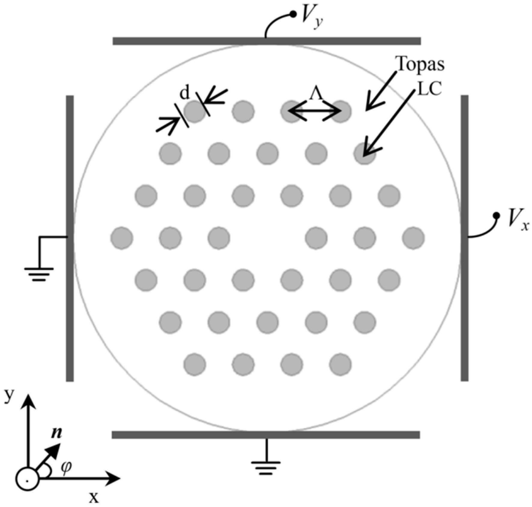
2. Design of the THz LC-MOF

The cross-section of the designed LC-MOF is shown in Figure 1. We constructed the fiber cladding by arranging circular holes (with hole diameter d) in a triangular lattice pattern (with lattice constant Λ) in the background of Topas COC. The cladding holes were infiltrated with 5CB. As the refractive indices of 5CB (no ≈ 1.58, ne ≈ 1.77, 25 °C) [17] are higher than the refractive index of background material Topas (nb = 1.5258) [11] in the THz frequency range, the propagation mechanism of the designed LC-MOF is based on the PBG effect.
Several factors should be considered to design suitable fiber structural parameters. Firstly, an appropriate value of d and Λ should be adopted to insure the cladding of the LC-MOF has PBGs in the THz frequency range (0.2 ~ 3 THz) and the unfilled index guiding MOF (with a triangular air-hole lattice cladding) is endlessly single-mode, i.e., the hole diameter to pitch ratio (d/Λ) should be less than 0.45 [23]. Secondly, the number of the cladding hole rings is also an important structural parameter. Too many cladding hole rings increase the outer diameter of the fiber to several millimeters, and reduce both the flexibility and the tuning response rate of the THz LC-MOF, as Λ is comparable to the guiding wavelength. However, the high-index inclusions (i.e., the LC cylinders embedded in the low-index Topas background) are responsible for the PBG guiding mechanism and confinement loss [24]. Decreasing the number of the cladding hole rings diminish the PBG effect and lead to a significant increase in confinement loss [16]. Considering the compromise between the flexibility and confinement loss of the fiber, three rings of cladding holes with d/Λ = 0.4 were adopted for the optimized THz LC-MOF. The designed structure is relatively simple and can be fabricated by the extrusion-stretching technique [25], which is suitable for mass production.
Local orientation for the rodlike molecules of the nematic liquid crystal 5CB is described by an unit vector n (as shown in Figure 1), i.e., the director, which is parallel to the direction of the average orientation of the molecules. Experimental results of Yuan et al. [26] show that the director of LC filled in the cladding holes (with diameter of several microns) of MOF is parallel to the fiber axis when temperature is below Tc and without external static electric (or magnetic) field across the fiber. Dielectric tensor of the nematic LC takes the form ε LC = diag ( n o 2 , n o 2 , n e 2 ) . However, the homogeneous alignment of LC filled in the cladding holes (with diameter about tens to hundreds of microns) of THz MOF could be achieved under the influence of the appropriate anchoring conditions [17].
When an external electric field is applied, the director can be reoriented along the applied field [27,28]. Almost uniform orientation of the director in the x–y plane can be controlled by two orthogonal sets of electrodes with sufficiently strong voltage as shown in Figure 1. So, the nonhomogeneity of the director was neglected in the following analysis for simplicity of calculation. Dielectric tensor of the nematic LC takes the form of:
ε r = [ ε x x ε x y 0 ε y x ε y y 0 0 0 ε z z ]
where
ε x x ( r ) = ε o ( r ) sin 2 φ + ε e ( r ) cos 2 φ
ε x y ( r ) = ε y x ( r ) = [ ε e ( r ) ε o ( r ) ] sin φ cos φ
ε y y ( r ) = ε o ( r ) cos 2 φ + ε e ( r ) sin 2 φ
ε z z ( r ) = ε o ( r )
φ is the rotation angle of the director with the x-axis, and it can be arbitrarily controlled by the external static electric field.

3. Results and Discussion

A full-vector FEM method [29,30] was employed to investigate the PBGs and guided modes properties of the designed THz LC-MOF.

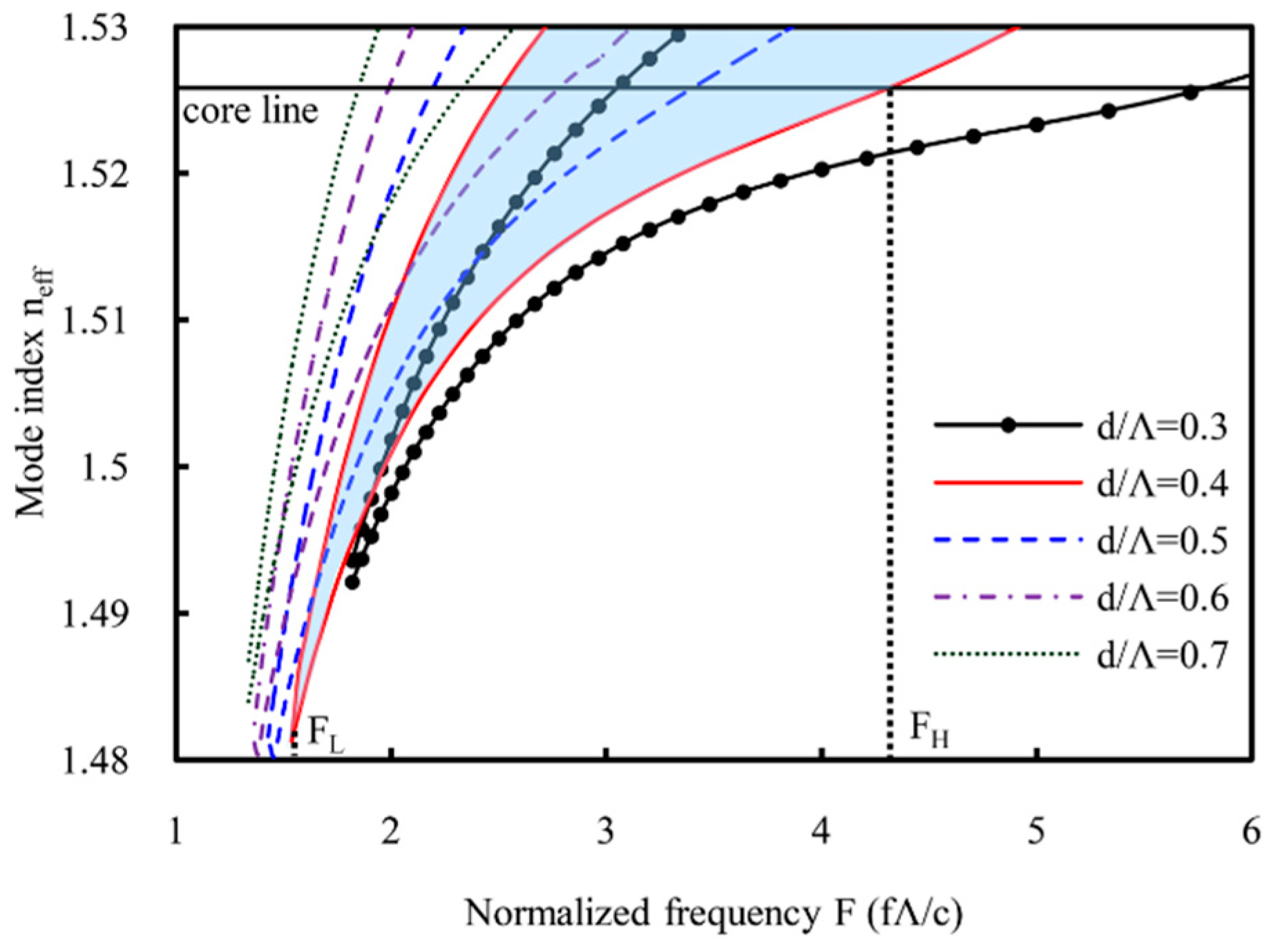
3.1. Structural Parameter Dependence of Bandgaps

Bandgaps of the infinitely cladding structure (periodic triangular lattice of LC inclusions in a background of Topas COC) without external static electric field across the fiber (Vx,y = 0 and director is parallel to the z-axis) were calculated. Figure 2 shows the first bandgap (boundary lines) of the cladding structure with different d/Λ. The vertical axis is effective mode index neff, and the horizontal axis is normalized frequency F = fΛ/c. For a certain d/Λ, the area between the corresponding boundary lines represents the bandgap in which the cladding modes are forbidden and the core modes are guided. The blue shaded region shows the bandgap of the cladding structure with d/Λ = 0.4. The horizontal core-line corresponding to refractive index of Topas represents the boundary between states that are propagating or evanescent in the cladding. The bandgap can be characterized by the highest bandgap frequency FH (where the high frequency bandgap boundary line crosses the core-line) and the lowest bandgap frequency FL (corresponding to the low-frequency edge at the bottom of the PBG, as shown in Figure 2). The maximum transmission bandwidth and the central frequency of the transmission band can be expressed by ΔF = FH − FL and Fc = (FH + FL)/2, respectively. Then, the relative bandwidth is defined as: ΔF/Fc.
It can be seen that the increment of the d/Λ drastically shifts the bandgap towards a lower frequency. The cladding structure with d/Λ = 0.4 has lower central frequency (Fc = 2.9) than the cladding structures with d/Λ = 0.3 (Fc = 3.8), which means the former has a smaller fiber diameter and thus better flexibility than the later with the same central frequency. According to the structural parameter dependence of bandgaps, as shown in Figure 2, the bandgap can be moved to certain frequency in the range of 0.2–1.5 THz (in which the material dispersion of Topas and 5CB is negligible) by scaling and tailoring the structural parameters of the fiber. For example, if we need a 5CB-filled Topas MOF that has a bandgap centered at 1 THz, it is possible to set structural parameters d = 348 μm, and d/Λ = 0.4 or d = 342 μm and d/Λ = 0.3. As the bandgaps are formed based on antiresonances of the individual LC inclusions, so are the positions of the bandgaps strongly dependent on the cladding-hole diameter and weakly on the lattice constant [31].
The cladding structure with d/Λ = 0.4 has a wider relative bandwidth (ΔF/Fc = 0.97) than the cladding structures with d/Λ = 0.5, 0.6 and 0.7. In addition, the unfilled index-guiding MOF with d/Λ = 0.4 (less than 0.45) is endlessly single-mode [23]. For applications such as polarizers [28], filters [32], and switches [33], only a short piece of LC-MOF is required. The LC-MOF is always a short section of the entire fiber, and the main origin of the insertion loss is the coupling loss between the index-guiding section and the bandgap-guiding section [19,20,26]. Besides the inherent advantage of single-mode propagation, the endlessly single-mode property of the unfilled MOF can reduce the coupling loss between the unfilled section and the filled section in a wide frequency range as a result of the well-confined characteristic of the fundamental mode. So, the structure with d/Λ = 0.4 is adopted for the optimized THz LC-MOF.

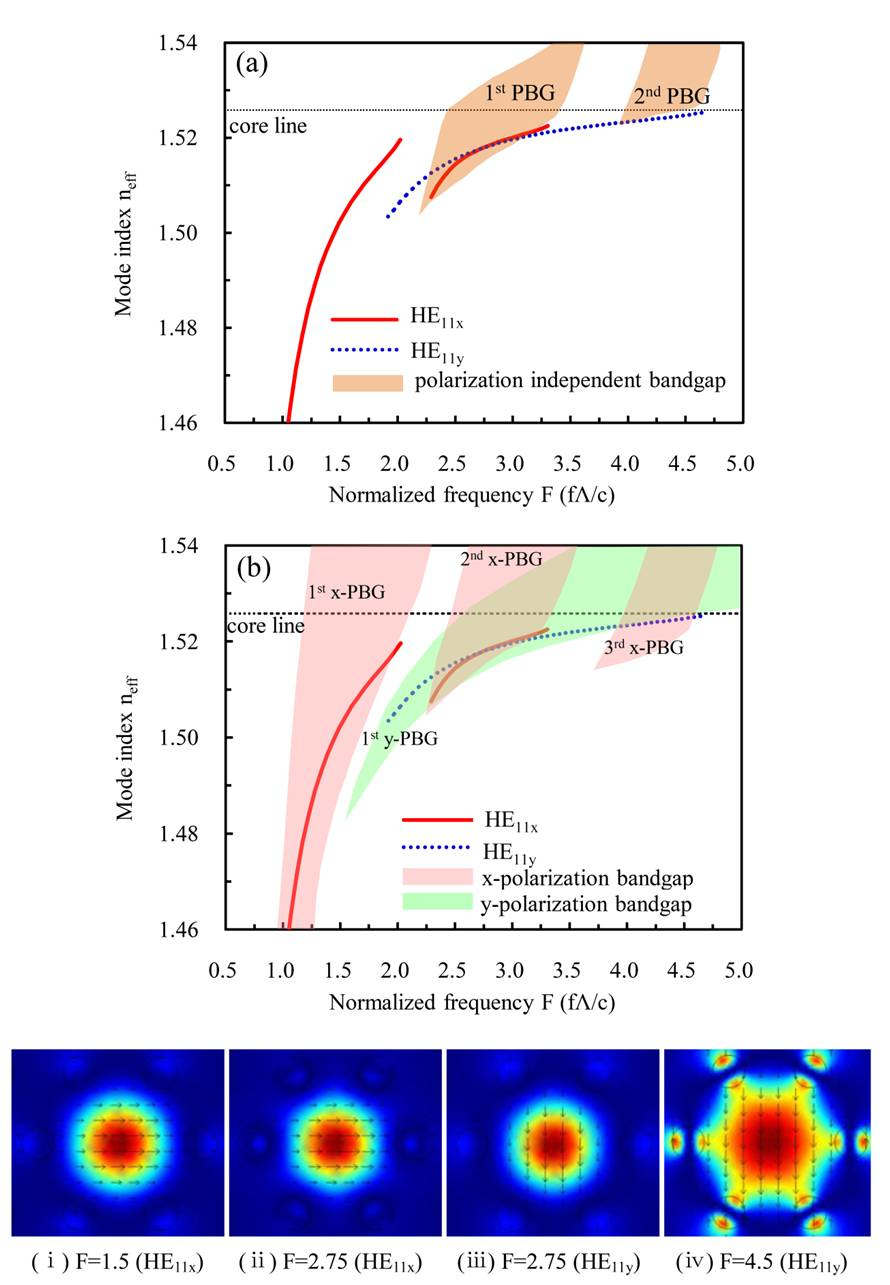
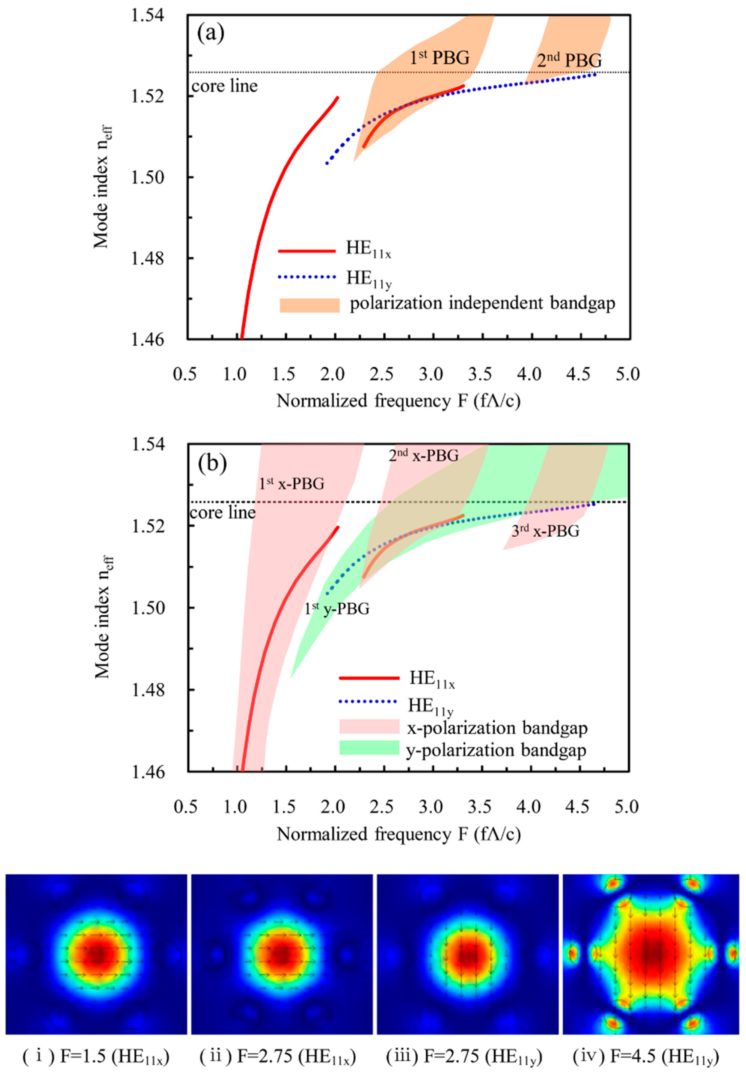
3.2. Polarization Dependence of the Electrically Tunable Bandgaps

Once an external electric field is applied across the fiber, the director can be reoriented along the applied field, which is an inherent property of nematic LC [34]. For instance, if the applied field is along the x-axis (Vx = V0, Vy = 0), then the rotation angle of the director φ is 0, and the dielectric tensor of the LC takes a form ε LC = diag ( n e 2 , n o 2 , n o 2 ) [21,22]. The alignment of the LC director is actually not homogeneous even though the external electric field is high enough, since it is dependent on the geometry of the LC director and the effect of strong boundary conditions [35]. For simplicity in numerical analysis, the nonhomogeneity of the director was neglected in this paper. The bandgap characteristics of the infinite cladding structure (d/Λ = 0.4) with an external electric field applied along the x-axis were studied. There exist two effective polarization-independent total bandgaps in which both the x-polarized fundamental modes HE11x and the y-polarized fundamental modes HE11y can be guided, as shown in Figure 3a. However, the modal-dispersion curves for both the HE11x and HE11y modes exceed the polarization-independent total bandgaps. So, the polarization-independent total bandgaps are insufficient to describe the propagation properties of the LC-MOF when external electric field is applied across the fiber, and it is necessary to investigate the polarization-dependent bandgaps [22].
The index contrast between LC and the background material (no/nb, ne/nb), and the anisotropy of LC (ne/no) were not significantly large; therefore, the coupling effect between two polarization components of the electric field vector could be neglected [21]. The x- and y-polarization bandgaps can be evaluated by using the cladding structure with ε LC = diag ( n e 2 , n e 2 , n o 2 ) and ε LC = n o 2 , respectively. Figure 3b shows the polarization-dependent bandgaps obtained by neglecting the coupling effect. The pink and green shaded regions show the x- and y-polarization bandgaps, respectively. Comparing Figure 2 and Figure 3b, it can be found that the external electric field causes bandgap splitting, and shifts the x-polarization bandgaps towards a lower frequency due to the high difference between no and ne. The dispersion curves of the x- and the y-polarized fundamental modes are coincidental with the x- and y-polarization bandgaps, respectively. Thus, the x(y)-polarized modes are supported by the corresponding x(y)-polarization bandgaps. The overlap regions of the x- and y-polarization bandgaps in Figure 3b represent the polarization-independent total bandgaps, which are consistent with that in Figure 3a. Therefore, ignoring coupling terms yields little change to the bandgaps. The polarization-dependent bandgap splitting caused by the transverse electric field can give rise to some interesting characteristics, such as electrically tunable high birefringence or single-mode single polarization propagation of THz wave.

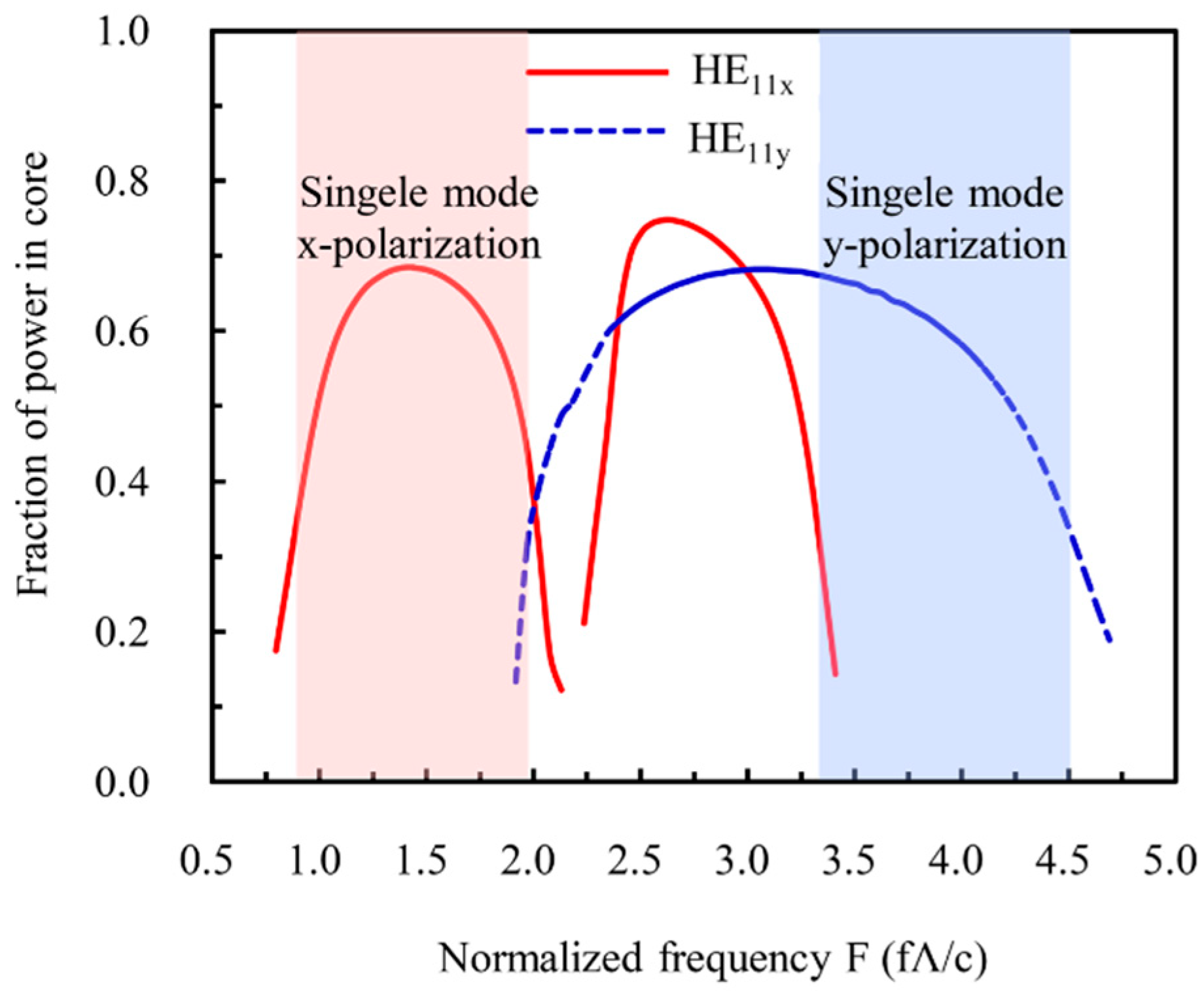
3.3. Guided-Mode Properties of the Designed THz LC-MOF

Although position of the PBGs and the maximum transmission bandwidth (ΔF = FH − FL) can be estimated from the bandgap diagram of the infinitely cladding structure, 3 dB bandwidth of the bandgap-guiding MOF is narrower than ΔF. It is necessary to study guided mode properties of the designed THz LC-MOF. Lower panels in Figure 3 show mode profiles and transverse electric-field distributions (arrow diagram) of the fundamental modes. Figure 3i, ii is the mode profile of HE11x at the central frequency of the first and second x-polarization PBGs, respectively. It can be seen that the second PBG provides better confinement for the guided mode than the first PBG. Figure 3iii, iv is the mode profile of HE11y at the central frequency and high-frequency edge of the first y-polarization PBG, respectively. It can be found that the bandgap effects confined most energy of the guided mode in the fiber core around the central frequency of the bandgap, but the fundamental mode is diffused in cladding region with the guided frequency approaching the bandgap edge, which leads to increasing transmission loss, as explained blow.
Figure 4 shows the fraction of core (with radius of Λ / 3 ) confined energy for the HE11x within the first and second x-polarization PBGs (solid red lines), and HE11y within the first y-polarization PBG (dashed blue line). Comparing Figure 3b and Figure 4, it can be found that the maximum (more than 60%) of the core confined energy fraction is near the central frequency of the relevant bandgaps. The core confined energy fraction decreases rapidly as the guided frequency approaches the bandgap edges. The power spreads to the cladding (especially to the first ring of LC inclusions, which has much higher material loss than Topas [11,17], as shown in Figure 3iv) and escapes from the entire structure when it disappears from the core. This leads to high absorption loss and confinement loss (see Section 3.4). So, the fraction of core confined energy of the fundamental mode against frequency could provide a qualitative estimation of the fiber’s transmission spectrum.
The guided mode is considered to be cut off when the core confined energy is reduced to half of its maximum value. There are two distinct frequency regions where single-mode single-polarization guidance occurred, as the shaded regions show in Figure 4. Between the first and second x-polarization PBGs, the x-polarized fundamental mode also had a minimum of the core confined energy around the normalized frequency F = 2.2. The experimental results of Noordegraaf et al. [20] and Liu et al. [36] show that the spectral dip (corresponding to the resonant frequency of the individual high-index inclusion) is consistent with the frequency region between two adjacent bangaps. So, the minimum of the core confined energy between the first and second x-polarization PBGs would give rise to a spectral dip of the x-polarized fundamental mode for the designed THz LC-MOF. This spectral dip can be utilized for making tunable optical filters [37,38].

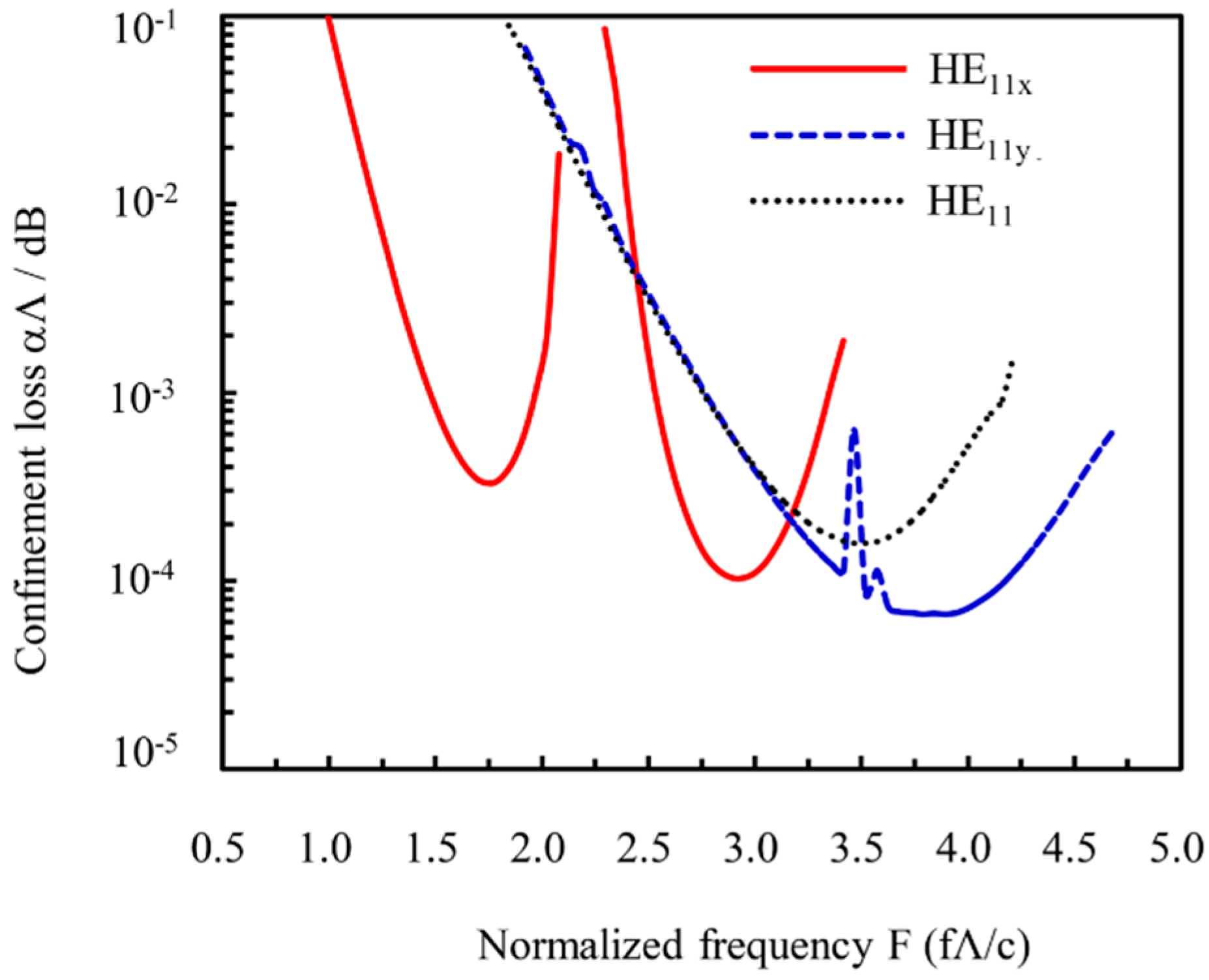
3.4. Electrically Tunable Confinement Loss of the Designed THz LC-MOF

For realistic MOFs, the fundamental modes are inherently leaky as a result of the finite number of air-hole rings in the cladding region. So, confinement loss inevitably occurs. The addition of more cladding hole rings could reduce mode confinement loss (proportional to the imaginary part of the effective-mode index), but also increase the outer diameter of the fiber. In order to be flexible and compact, the THz fiber should be as thin as possible. The transmission loss of the solid core THz MOF is also mainly derived from material absorption loss rather than confinement loss. Thus, only three rings of cladding holes are adopted for the designed THz LC-MOF.
Confinement losses (normalized to αΛ, in decibels) of the fundamental modes with and without external electric field applied across the fiber are studied and shown in Figure 5. The two fundamental modes are degenerate for the THz LC-MOF without an external electric field applied, and confinement loss as a function of normalized frequency is shown by the dotted black line. However, the external electric field caused bandgap splitting. The confinement loss for the HE11x within the first and second x-polarization PBGs and HE11y within the first y-polarization PBG are shown by the solid red lines and dashed blue line, respectively. It can be seen that confinement loss becomes minimal around the center of PBGs and increases as approaching the band edges. The second x-polarization PBG provides lower confinement loss than the first one. The high confinement loss peaks of the HE11y around the normalized frequency F = 3.5 is corresponding to the cut-off frequency of the second modes of x-polarization bandgap. We attribute the appearance of high confinement loss peaks of HE11y to the coupling between the y-polarization core mode and the second x-polarization band of the cladding structure [39]. An external electric field applied across the fiber can broaden the effective transmission bandwidth and achieve single-polarization guidance for the designed THz LC-MOF. The electrically tunable single-mode single-polarization guidance can be utilized for applications of the THz LC-MOF for dynamic polarization control.

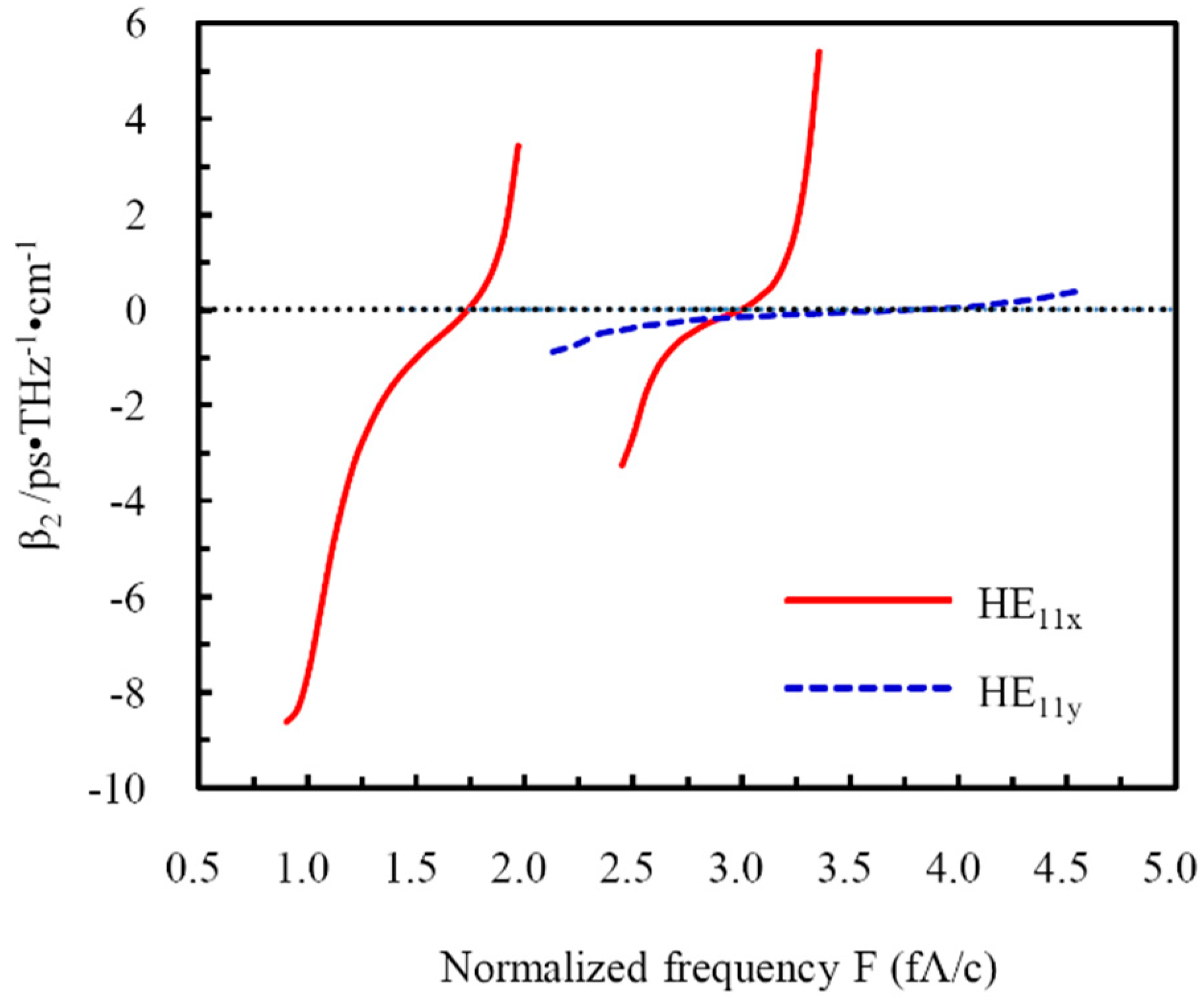
3.5. Dispersion Properties of the Designed THz LC-MOF

For THz systems that use broadband-pulsed THz sources, it is necessary to adopt low group velocity-dispersion waveguides in order to prevent the degradation of the pulse shape. In the THz region, group velocity dispersion (GVD) could be quantified as follows:
β 2 = 1 2 π c ( 2 n eff f + f 2 n eff f 2 )
in ps/THz/cm. The GVD curves of the x- and the y-polarized fundamental modes are shown in Figure 6. It can be seen that the dispersion parameters change rapidly with the guided frequency approaching the bandgap edge, and the x-polarized fundamental mode has zero dispersion around normalized frequency F = 1.75 and F = 3 within the first and second x-polarization PBGs, respectively. Flattened near-zero GVD of 0 ± 1 ps/THz/cm was obtained for the y-polarized fundamental mode within a broad normalized frequency range of 2.1–4.6.

4. Conclusions

An electrically tunable bandgap-guiding fiber for THz frequencies was designed by infiltrating the cladding air holes of an index-guiding MOF with nematic LC. The Topas polymer was chosen as the fiber base material because of its relatively low absorption loss and extremely low material dispersion in the 0.2–2 THz range. In addition, 5CB was chosen as the filling material because of its wide nematic range around room temperature, relatively small extinction coefficient, large birefringence, and, thus, higher electrical tunability in the frequency range of 0.2–1.0 THz. Structural dependence of the bandgap for the designed THz LC-MOF without an external static electric field across the fiber was studied in detail. The structural parameters of the LC-MOF that had PBG centered at 1 THz are given. The PBG could also be transposed to certain frequency by scaling the fiber structure. Due to the strong anisotropy of 5CB, external electric field applied across the fiber can cause polarization-dependent bandgap splitting, and thus broaden the effective transmission bandwidth and achieve single mode single polarization guidance. Propagation properties, such as mode property, confinement loss, and the dispersion of the designed THz LC-MOF show electrical tunability. A flattened near-zero GVD of 0 ± 1 ps/THz/cm was obtained for the y-polarized fundamental mode within a broad normalized frequency range. These results can provide theoretical references for applications of LC-MOF for dynamic polarization control and tunable fiber-optic devices in THz frequencies.

Author Contributions

D.W. designed the structure and wrote the article; C.M. performed the numerical simulations; B.L. put forward the idea and analyzed the data; J.Y. checked the spelling and grammar of this article, and put forward some comments (data curation, C.M.; funding acquisition, D.W.; investigation, D.W.; methodology, B.L.; software, C.M.; supervision, D.W.; writing—original draft, D.W.; writing—review and editing, J.Y.).

Funding

This research was funded by the National Natural Science Foundation of China (Grant Nos. 11604260 and 11605133).

Acknowledgments

This work was supported by the National Natural Science Foundation of China (Grant Nos. 11604260 and 11605133).

Conflicts of Interest

The authors declare no conflict of interest.

References

  1. Jacobsen, R.H.; Mittleman, D.M.; Nuss, M.C. Chemical recognition of gases and gas mixtures with terahertz waves. Opt. Lett. 1996, 21, 2011–2013. [Google Scholar] [CrossRef] [PubMed]
  2. Awad, M.M.; Cheville, R.A. Transmission terahertz waveguide-based imaging below the diffraction limit. Appl. Phys. Lett. 2005, 86, 221107. [Google Scholar] [CrossRef]
  3. Zhang, J.Q.; Grischkowsky, D. Waveguide terahertz time-domain spectroscopy of nanometer water layers. Opt. Lett. 2004, 29, 1617–1619. [Google Scholar] [CrossRef] [PubMed]
  4. Federici, J.; Moeller, L. Review of terahertz and subterahertz wireless communications. J. Appl. Phys. 2010, 107, 111101. [Google Scholar] [CrossRef]
  5. Wang, K.; Mittleman, D.M. Metal wires for terahertz wave guiding. Nature 2004, 432, 376–379. [Google Scholar] [CrossRef] [PubMed]
  6. Mendis, R.; Grischkowsky, D. Plastic ribbon THz waveguides. J. Appl. Phys. 2000, 88, 4449–4451. [Google Scholar] [CrossRef]
  7. Han, H.; Park, H.; Cho, M.; Kim, J. Terahertz pulse propagation in a plastic photonic crystal fiber. Appl. Phys. Lett. 2002, 80, 2634–2636. [Google Scholar] [CrossRef] [Green Version]
  8. Wu, D.S.; Argyros, A.; Leon-Saval, S.G. Reducing the size of hollow terahertz waveguides. J. Lightwave Technol. 2011, 29, 97–103. [Google Scholar] [CrossRef]
  9. Atakaramians, S.; Shahraam, A.V.; Monro, T.M.; Abbott, D. Terahertz dielectric waveguides. Adv. Opt. Photonics 2013, 5, 169–215. [Google Scholar] [CrossRef]
  10. Nielsen, K.; Rasmussen, H.K.; Jepsen, P.U.; Bang, O. Porous-core honeycomb bandgap THz fiber. Opt. Lett. 2011, 36, 666–668. [Google Scholar] [CrossRef]
  11. Nielsen, K.; Rasmussen, H.K.; Adam, A.J.; Planken, P.C.; Bang, O.; Jepsen, P.U. Bendable, low-loss Topas fibers for the terahertz frequency range. Opt. Express 2009, 17, 8592–8601. [Google Scholar] [CrossRef] [PubMed]
  12. Khanarian, G. Optical properties of cyclic olefin copolymers. Opt. Eng. 2001, 40, 1024–1029. [Google Scholar] [CrossRef]
  13. Ung, B.; Mazhorova, A.; Dupuis, A.; Rozé, M.; Skorobogatiy, M. Polymer microstructured optical fibers for terahertz wave guiding. Opt. Express 2011, 19, B848–B861. [Google Scholar] [CrossRef] [PubMed]
  14. Lu, J.Y.; Yu, C.P.; Chang, H.C.; Chen, H.W.; Li, Y.T.; Pan, C.L.; Sun, C.K. Terahertz air-core microstructure fiber. Appl. Phys. Lett. 2008, 92, 064105. [Google Scholar] [CrossRef]
  15. Larsen, T.T.; Broeng, J.; Hermann, D.S.; Bjarklev, A. Optical devices based on liquid crystal photonic bandgap fibres. Opt. Express 2003, 11, 2589–2596. [Google Scholar] [CrossRef]
  16. Argyros, A.; Birks, T.A.; Leon-Saval, S.G.; Cordeiro, C.M.B.; Russell, P.S.J. Guidance properties of low-contrast photonic bandgap fibres. Opt. Express 2005, 13, 2503–2511. [Google Scholar] [CrossRef]
  17. Pan, R.P.; Hsieh, C.F.; Pan, C.L.; Chen, C.Y. Temperature-dependent optical constants and birefringence of nematic liquid crystal 5CB in the terahertz frequency range. J. Appl. Phys. 2008, 103, 093523. [Google Scholar] [CrossRef]
  18. Tsai, T.R.; Chen, C.Y.; Pan, R.P.; Pan, C.L. Electrically controlled room temperature terahertz phase shifter with liquid crystal. IEEE Microw. Wirel. Compon. Lett. 2004, 14, 77–79. [Google Scholar] [CrossRef]
  19. Alkeskjold, T.T.; Lægsgaard, J.; Bjarklev, A.; Hermann, D.S.; Broeng, J.; Li, J.; Gauza, S.; Wu, S.T. Highly tunable large-core single-mode liquid-crystal photonic bandgap fiber. Appl. Opt. 2006, 45, 2261–2264. [Google Scholar] [CrossRef] [Green Version]
  20. Noordegraaf, D.; Scolari, L.; Lægsgaard, J.; Alkeskjold, T.T.; Tartarini, G.; Borelli, E.; Bassi, P.; Li, J.; Wu, S.T. Avoided-crossing-based liquid-crystal photonic-bandgap notch filter. Opt. Lett. 2008, 33, 986–988. [Google Scholar] [CrossRef]
  21. Sun, J.; Chan, C.C. Effect of liquid crystal alignment on bandgap formation in photonic bandgap fibers. Opt. Lett. 2007, 32, 1989–1991. [Google Scholar] [CrossRef] [PubMed]
  22. Ren, G.B.; Shum, P.; Hu, J.J.; Xu, X.; Gong, Y.D. Polarization-dependent bandgap splitting and mode guiding in liquid crystal photonic bandgap fibers. J. Lightw. Technol. 2008, 26, 3650–3659. [Google Scholar] [CrossRef]
  23. Mortensen, N.A. Effective area of photonic crystal fibers. Opt. Express 2002, 10, 341–348. [Google Scholar] [CrossRef] [PubMed]
  24. Bouwmans, G.; Pureur, V.; Betourne, A.; Quiquempois, Y.; Perrin, M.; Bigot, L.; Douay, M. Progress in solid core photonic bandgap fibers. Opt. Quant Electron. 2007, 39, 949–961. [Google Scholar] [CrossRef]
  25. Wang, J.; Yang, X.H.; Wang, L.L. Fabrication and experimental observation of monolithic multi-air-core fiber array for image transmission. Opt. Express 2008, 16, 7703–7708. [Google Scholar] [CrossRef] [PubMed]
  26. Yuan, W.; Wei, L.; Alkeskjold, T.T.; Bjarliev, A.; Bang, O. Thermal tunability of photonic bandgaps in liquid crystal infiltrated microstructured polymer optical fibers. Opt. Express 2009, 17, 19356–19364. [Google Scholar] [CrossRef] [PubMed]
  27. Zografopoulos, D.C.; Kriezis, E.E.; Tsiboukis, T.D. Photonic crystal-liquid crystal fibers for single-polarization or high-birefringence guidance. Opt. Express 2006, 14, 914–925. [Google Scholar] [CrossRef]
  28. Alkeskjold, T.T.; Bjarklev, A. Electrically controlled broadband liquid crystal photonic bandgap fiber polarimeter. Opt. Lett. 2007, 32, 1707–1709. [Google Scholar] [CrossRef]
  29. Sadiku, M.N.O. Numerical Techniques in Electromagnetics, 2nd ed.; CRC Press: New York, NY, USA, 2001. [Google Scholar]
  30. Saitoh, K.; Koshiba, M. Leakage loss and group velocity dispersion in air-core photonic bandgap fibers. Opt. Express 2003, 11, 3100–3109. [Google Scholar] [CrossRef]
  31. Luan, F.; George, A.K.; Hedley, T.D.; Pearce, G.J.; Bird, D.M.; Knight, J.C.; St. J. Russell, P. All-solid photonic bandgap fiber. Opt. Lett. 2004, 29, 2369–2371. [Google Scholar] [CrossRef]
  32. Wei, L.; Alkeskjold, T.T.; Bjarklev, A. Electrically tunable bandpass filter using solid-core photonic crystal fibers filled with multiple liquid crystals. Opt. Lett. 2010, 35, 1608–1610. [Google Scholar] [CrossRef] [PubMed]
  33. Lee, H.R.; Hsiao, V.K.S. Photoactive photonic liquid crystal fiber polarization switches. Opt. Fiber. Technol. 2013, 19, 623–626. [Google Scholar] [CrossRef]
  34. Khoo, I.C. Liquid Crystals: Physical Properties and Nonlinear Optical Phenomena, 1st ed.; Wiley: New York, NY, USA, 1994. [Google Scholar]
  35. Jeong, Y.; Yang, B.; Lee, B.; Seo, H.S.; Choi, S.; Oh, K. Electrically controllable long-period liquid crystal fiber gratings. IEEE Photonic Technol. 2000, 12, 519–521. [Google Scholar] [CrossRef]
  36. Liu, Y.; Wang, Y.; Sun, B.; Liao, C.; Song, J.; Yang, K.; Wang, G.; Wang, Q.; Yin, G.; Zhou, J. Compact tunable multibandpass filters based on liquid-filled photonic crystal fibers. Opt. Lett. 2014, 39, 2148–2151. [Google Scholar] [CrossRef] [PubMed]
  37. Vieweg, N.; Born, N.; Al-Naib, I.; Koch, M. Electrically Tunable Terahertz Notch Filters. J. Infrared Milli. Terahz. Waves 2012, 33, 327–332. [Google Scholar] [CrossRef]
  38. Litchinitser, N.M.; Steinvurzel, P.E.; Eggleton, B.J.; White, T.P.; McPhedran, R.C.; Sterke, C.M. Application of an ARROW model for designing tunable photonic devices. Opt. Express 2004, 12, 1540–1550. [Google Scholar] [CrossRef] [PubMed]
  39. Ren, G.; Ping, S.; Yu, X.; Hu, J.J.; Wang, G.; Gong, Y. Polarization dependent guiding in liquid crystal filled photonic crystal fibers. Opt. Commun. 2008, 281, 1598–1606. [Google Scholar] [CrossRef]
Figure 1. Cross section of the liquid-crystal microstructured optical fiber (LC-MOF) and diagram for arbitrarily controlling the orientation of the nematic director in the x–y plane by two orthogonal sets of electrodes with voltage, Vx and Vy.
Applsci 08 02487 g001
Figure 2. Bandgaps of cladding structure for the designed THz LC-MOF without external static electric field across the fiber, ε LC = diag ( n o 2 , n o 2 , n e 2 ) .
Applsci 08 02487 g002
Figure 3. Bandgaps and modal dispersion curves for polarized fundamental modes HE11x (solid red line) and HE11y (dotted blue line) of the THz LC-MOF (d/Λ = 0.4) with rotation angle of the LC director φ = 0. (a) Polarization-independent total bandgaps, (b) polarization-dependent bandgaps. Bottom: mode profiles and transverse electric-field distributions (arrow diagram).
Applsci 08 02487 g003
Figure 4. Fraction of core confined energy as a function of normalized frequency and single-mode single-polarization operation regions of the designed THz LC-MOF.
Applsci 08 02487 g004
Figure 5. Confinement losses for degenerate fundamental mode HE11 (without an external electric field across the fiber) and polarized fundamental modes HE11x and HE11y (with an external electric field applied along the x-axis).
Applsci 08 02487 g005
Figure 6. Dispersion parameter as a function of normalized frequency.
Applsci 08 02487 g006

