Article

Tunable Liquid Crystal Based Phase Shifter with a Slot Unit Cell for Reconfigurable Reflectarrays in F-Band

National Key Laboratory of Advanced Display Technology, Academy of Photoelectric Technology, Hefei University of Technology, Hefei 230009, China
*
Author to whom correspondence should be addressed.
Appl. Sci. 2018, 8(12), 2528; https://doi.org/10.3390/app8122528
Submission received: 23 October 2018 / Revised: 5 December 2018 / Accepted: 5 December 2018 / Published: 6 December 2018
(This article belongs to the Special Issue Liquid Crystal THz Photonics: Materials, Devices and Applications)

Abstract

:

Featured Application

The proposed phase shifter in the article can be used in millimeter wave and THz reconfigurable reflectarray antenna.

Abstract

An electrically tuned phase shifter based on the single slot unit cell and liquid crystal for a reconfigurable reflectarray antenna was presented. The simulation and measured results obtained at the F-band were used to demonstrate that the dielectric properties of a nematic state liquid crystal could be exploited to realize a slot unit cell phase shifter for the reconfigurable reflectarrays antennas. By reducing the inhomogeneous of the external electric field in the liquid crystal layer, a lower control voltage and improved model accuracy was obtained. In the experiments test, the achieved saturation bias voltage (10 V) was smaller than the previously reported structure, and the phase shift of the reflectarray greater than 300° was achieved in the frequency range 121.5–126 GHz. The maximum phase shift of 306° occurred at 124.5 GHz.

1. Introduction

The liquid crystal (LC) based reflectarray antenna is a common reconfigurable reflectarray antenna type [1,2,3,4]. This antenna type is widely used, especially at frequencies over 60 GHz [5,6,7]. Due to the advantages of a low profile, simple structure, and easy fabrication, the liquid crystal based reflectarray antennas have been discussed by many researchers, especially for the applications in the millimeter-wave and THz frequency ranges [8,9]. Hu et al., proposed a single resonant square patch reflectarray antenna, which had the capability of a phase shift of 180° [10]. To improve the phase and bandwidth capability, Perez Palomino et al., proposed the multi-resonant unit cells for a reconfigurable reflectarray antenna [11]. This antenna uses triple rectangular dipole patches placed in a parallel to achieve a large bandwidth while achieving a phase shift of more than 360°. Bildik et al., proposed rectangular elements achieved a phase shift of 546° at 77 GHz [12]. In [9], a tunable 2π LC phase shifter was reported at 357 GHz by using 40 V driving voltage. However, due to the small size of a dipole antenna, the coverage of the metal is insufficient. When a bias voltage is applied to a dipole, the orientation of the liquid crystal is uneven which compromises the accuracy. This problem exists in a series of the LC-based electrically tunable devices, including the absorbers, phase shifters, filters, etc., where the uneven liquid crystal layer is usually replaced by the equivalent dielectric constant, but that causes the difference between the actual and simulation values. Many methods were reported to improve accuracy. A block separately module was proposed in [13], to improve the design accuracy by dividing different copper layers of the liquid crystal layer into several regions, achieving the sub-regional simulation, but such a design requires a more complex design process. Graphene material was also used to reduce the inhomogeneity of the static electric field [14]. Lei Wang et al. used the few-layer porous graphene to generate the uniform static field and achieve a THz absorber [15]. However, the disadvantage is that it is impossible to control the voltage of each line.
Motivated by the previous works, we propose an LC-based electrically tunable slot phase shifter. The proposed slot unit cell phase shifter for the reflectarray system is designed, fabricated and tested. The electromagnetic reflecting characteristics of the reflectarray system are simulated and analyzed. It is proven that the proposed structure has the advantage of providing a more homogeneous static electric field. The comparison of the proposed phase shifter performances with the mentioned phase shifter are tabulated in Table 1. Due to the large patch area, the achieved saturation reduced the bias voltage by 50% compared with the previously reported ones. The performance of the proposed phase shifter is validated by the array consisting of 30 × 30 unit cells. In the experiments, a liquid crystal is employed to provide the tunable phase-shifting unit cells in the F frequency band. The results show that the proposed spatial phase shifter provides the phase shift and continuous tunability over a broad frequency range.

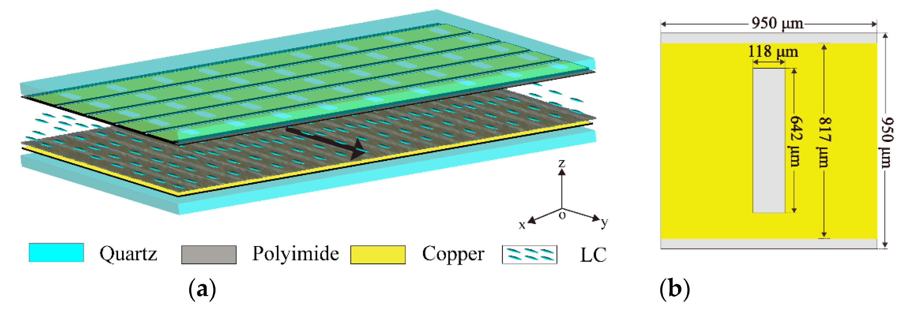
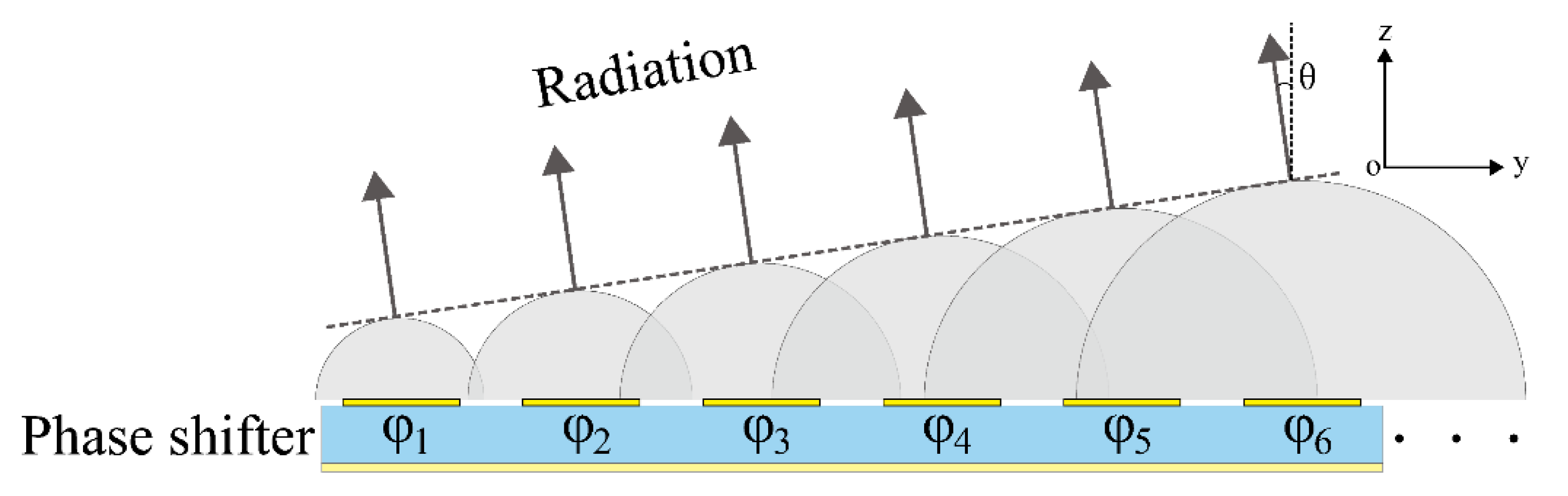
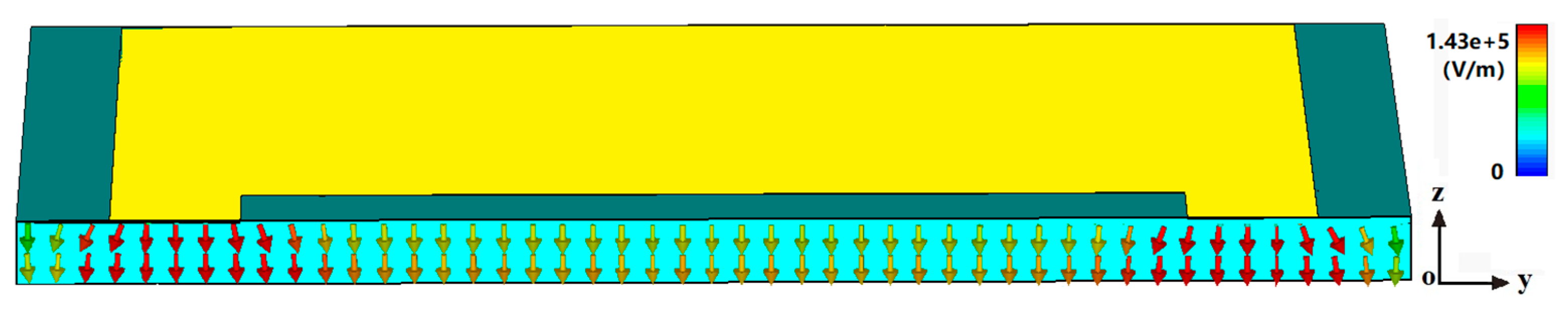
2. Design and Simulation

The nematic LC is an anisotropic material, which can be explained by its rod-like molecular structure. The electromagnetic properties of the LC, such as relative permittivity and loss tangent, depend on the LC molecules [17]. The orientation of LC molecules can be coordinated by the align layer and the external electric field. In the align layer, the grooves were created along a certain direction by mechanical friction, and the liquid crystal molecules are parallel to the groove under the groove anchoring energy. As shown in Figure 1a, the liquid crystal molecules’ orientation is parallel to the y-axis. If an external electric field is added, the orientation of the molecules will be forced parallel to electric field direction. By adjusting the external electric field, the relative permittivity of LC can be continuous controlled and resonant frequency of unit cells simultaneous changed. Many electrically tuned devices based on LC technology have been reported, such as phase shifters [18,19], absorbers [20,21], and filters [22,23,24].
As shown in Figure 1a, the proposed three-dimensional phase shifter. The unit cell is formed by two quartz plates (εr = 3.75; tanδ = 0.002), which are separated by the polystyrene microspheres and contain a 45 μm-thick LC. The copper patches which are printed on the quartz by evaporation method, have a conductivity of 5.8 × 10⁷ S/m and thickness of 500 nm. As shown in Figure 2, the reflection coefficients of the phase shifter have been simulated at different conductivity. It can be seen that reflection losses will increase as the metal conductivity decreases. Moreover, the thin polyimide (PI) layer is spin-coated on the copper surface to align the direction of unbiased LC molecules. The LC mixture (HFUT-HB01) is used in simulation and design. Its ordinary, extraordinary refractive indices are about 1.58 and 1.92 at 125 GHz, measured by terahertz time domain spectroscopy, as shown in Figure 3. Where its relative permittivity in the unbiased state (ε) and the fully biased state (ε//) was set to 2.47 and 3.6, respectively [9]. In the simulation, the loss tangent of the LC layer was set to 0.02. In each row all the cells are separated by an isolation slot to realize one-dimensional scanning. Figure 1b shows the geometrical dimensions of the resonant layer. The metal layer was separated by a 127 μm void at the x-axis. The list of the unit cell (along the x-axis) was connected, with the same bias voltage, and provided the same phase shift. The phase of the reflected wave is being adjusted at each row element, and a beam directing in the angle of θ can be obtained in the far field as shown in Figure 4.
The static electric field, which is distributed among the LC layer, is the most important characteristic of the LC tuned devices. We simulated the electric field’s direction and strength using the external electric field. The magnitude and direction of the external electric field in the center of x-axis cutting plane, when the 10 V voltage was applied to the two metal layers is shown in Figure 5. The electric field magnitude is defined by a color bar. The comprehensive analysis of the electric field direction and strength was conducted, and as it can be seen in Figure 5, after applying a bias voltage, the electric field in the LC layer was mostly uniform and parallel to the z-axis, and LC molecules’ direction was parallel to the z-axis.

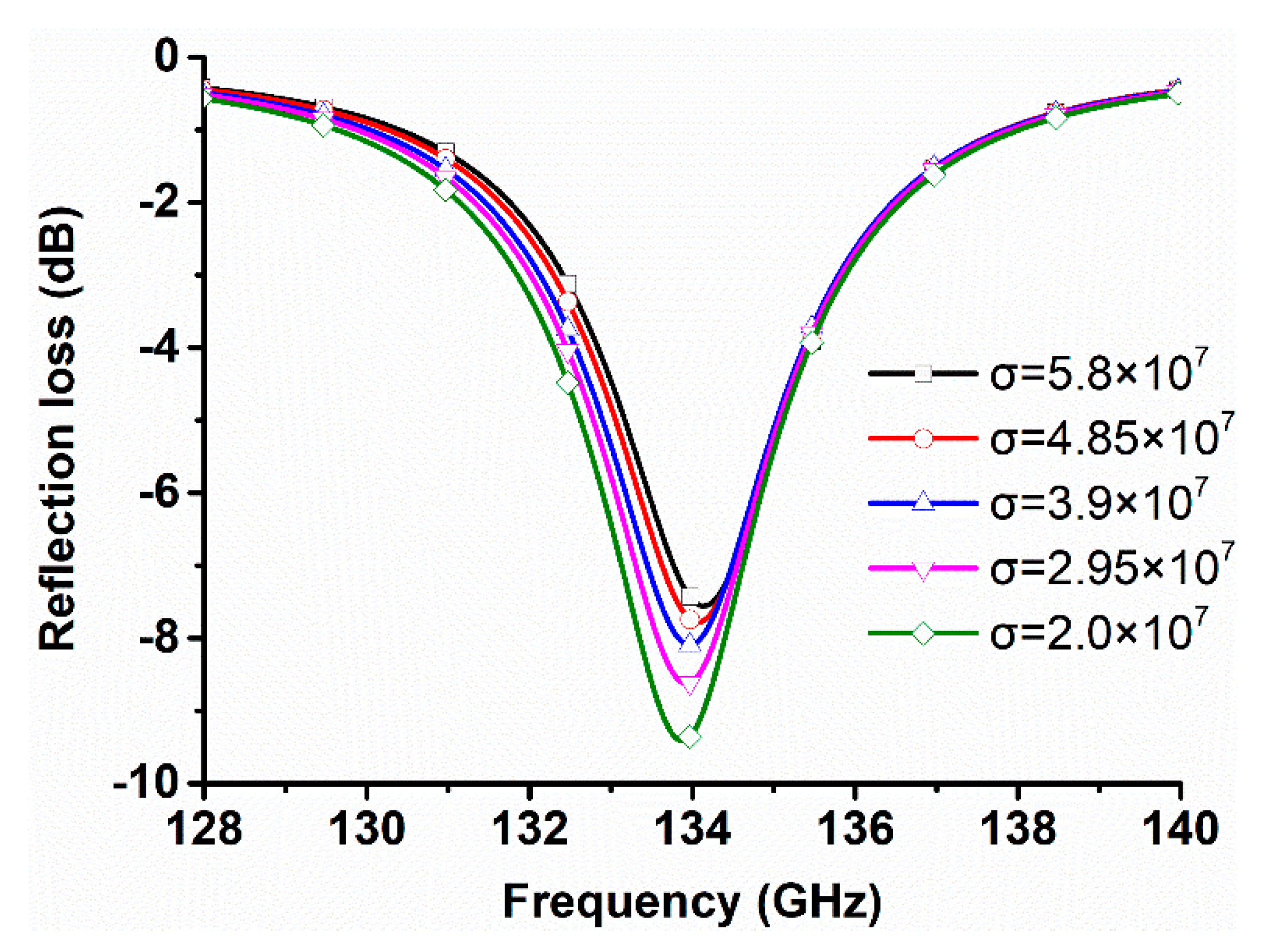
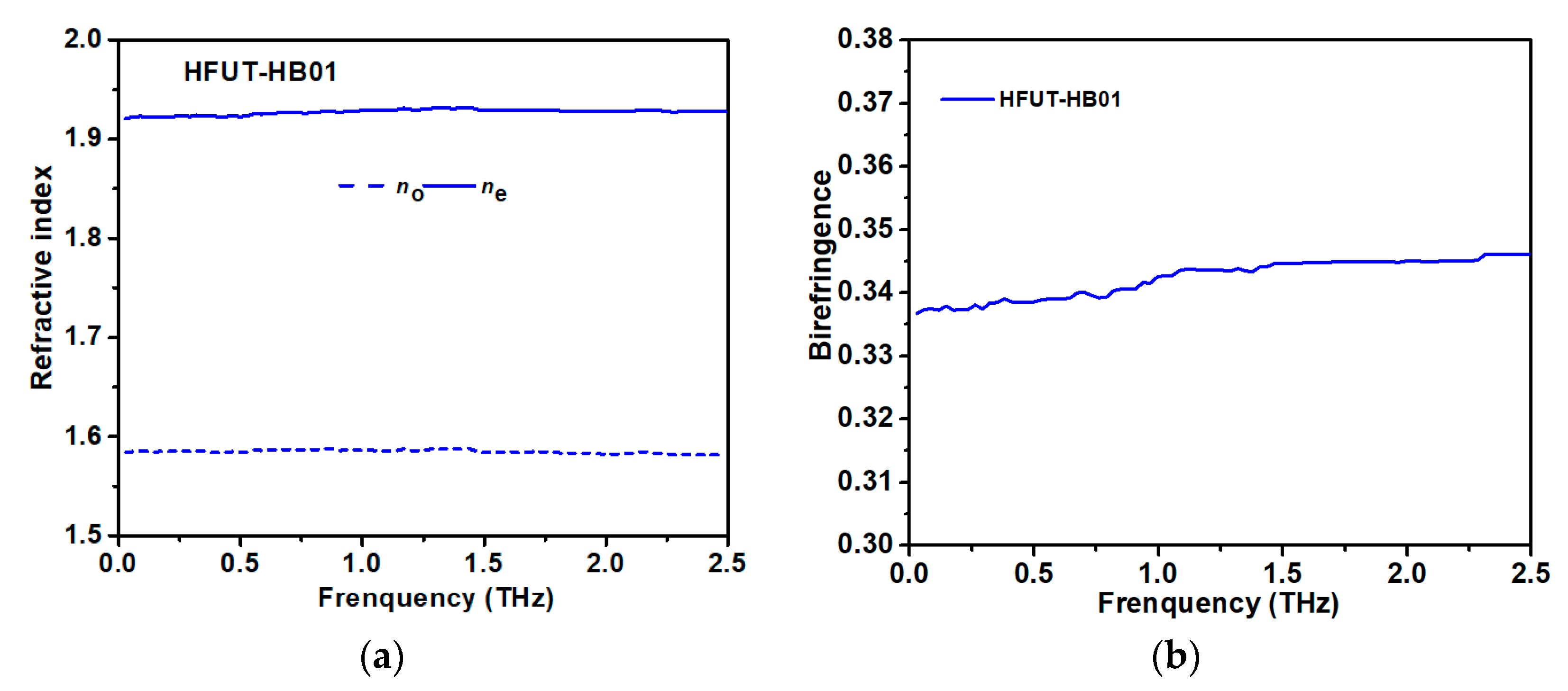
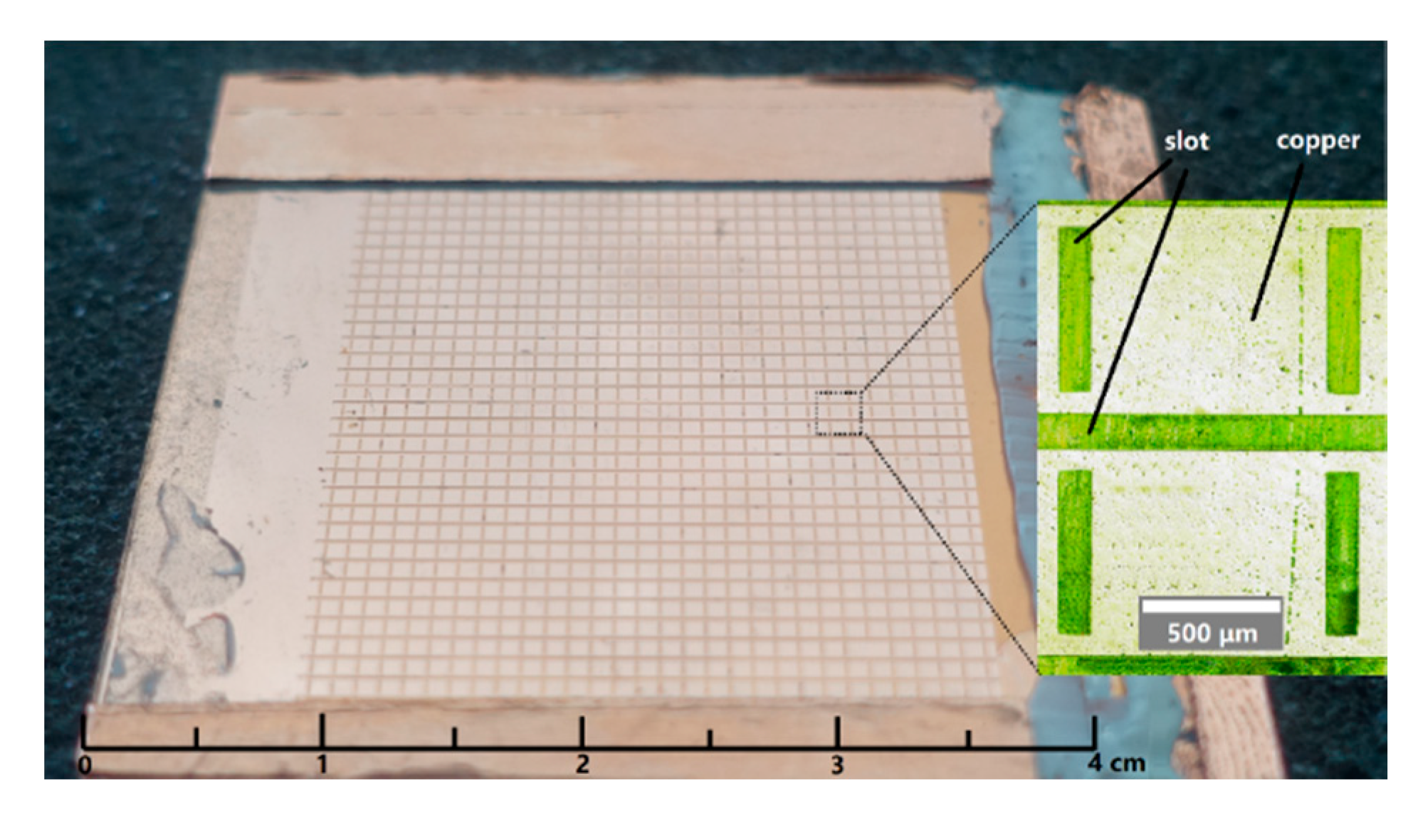
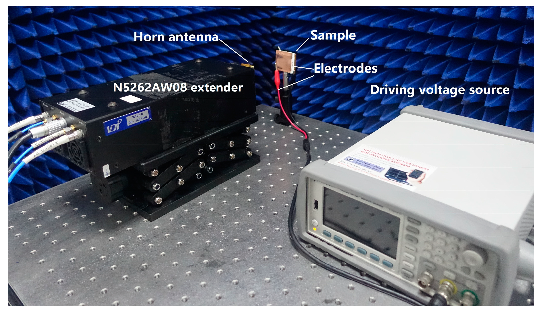
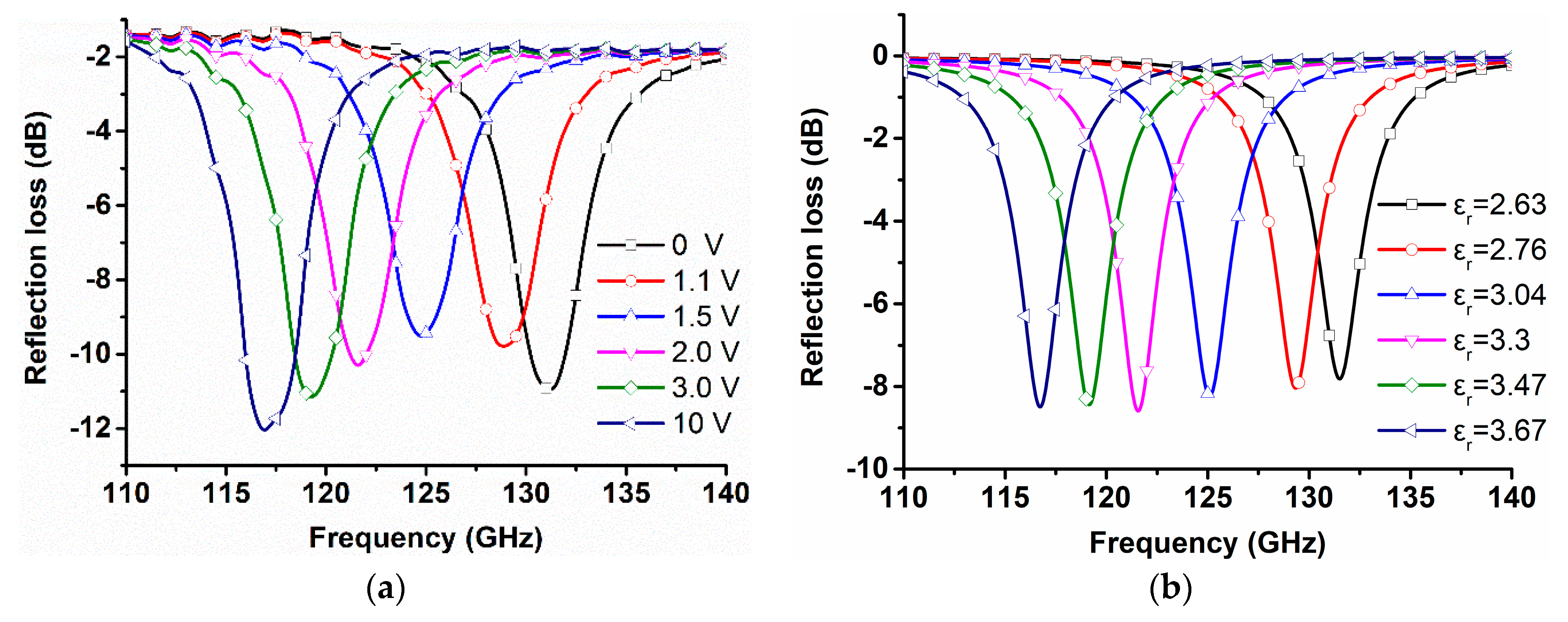
3. Experiments and Discussion

In this section, we experimentally validate the proposed phase shifter. The performance of the proposed LC-based phase shifter was analyzed by numerical finite difference time domain (FDTD) simulation. The prototype was fabricated by the ultraviolet light photoetching combined with the wet etching. The fabrication process consisted of the vacuum copper plating, photoresist spin coating, exposure, development, and wet etching. The sample and microscope image of the unit cell are shown in Figure 6, where it can be seen that the sample consisted of a 30 × 30 unit cells, printed on the 40 × 40 mm2 area on a quartz substrate with the thickness of 520 mm and thickness tolerance of ±10 μm. The unit cell structure had a dimensional tolerance of ±4 μm on the wide side and ±1 μm on the narrow side.
The measurement setup used in the experiments is shown in Figure 7. An Agilent N5224A vector network analyzer (Keysight Technologies, Inc., Santa Rosa, CA, USA) with N5262AW08 extender (Virginia Diodes, Inc., Charlottesville, VA, USA) was used to measure the spectral response of the fabricated structure. The free space measurements were used to obtain the scattering parameters in the frequency range from 110 to 140 GHz. In order to decrease the influence from the environment, the calibration was performed as follows: Firstly, calibrating the reflection amplitude on an ideal reflector. Secondly, the actual reflections from the sample were measured. Finally, compared the reflection from the sample and the reflection from the ideal reflector. In the experiments, a 1 kHz square wave with the maximum voltage of 10 V was energized between the ground and patches.
The orientation of molecules decided the permittivity of the LC. The rotation speed of LC molecules, which is independent on testing frequencies, is mainly determined by external voltage. The response time of the LC was investigated by measuring voltage-transmission curves in transparent test cells made with the same spacers as were used in the unit cell samples. The transmission experiment was realized with a HeNe-laser source and photodetector. As expected in test cells with a relatively large cell gap, a response time of 200 ms was found. The response times can potentially be pushed by including a small amount of in-situ generated polymer or copolymer in the samples [25,26,27,28].
The measured reflection amplitude at different voltages is presented in Figure 8a, wherein it can be seen that by increasing the bias voltage, the resonant frequency changed from 132 GHz (0 V bias) to 116 GHz (10 V bias). At the bias voltage of 10 V, most of the LC molecules were oriented parallel to the electric component of the static electric field, resulting in the relative permittivity similar to ε//. The loss of device is consisted of the ohmic loss in the copper layer, the absorption loss in the quartz plate and the LC layer, and resonant loss [29]. The test results also include the loss in free space, scattering loss, and receiving loss. As shown in Figure 8b, the simulation of reflection amplitude at different dielectric properties is obtained.
The simulation and experimental results in the working frequency range are presented in Figure 9. All phases were normalized relative phases to the simulated 0 V phase curve. The best-fit values for the LC substrate were shown to be ε = 2.63 at 0 V and ε// = 3.67 at 10 V. There was an approximate match between the predicted shift in the resonant frequency and the normalized experimental values of the phase test at bias voltages of 1.1 V, 1.2 V, 1.5 V, 2 V, 3 V, and 10 V. By increasing the bias voltage the resonant frequency was reduced and the matching relative permittivity was increased. As shown in Figure 10, the prototype achieved a phase shift of about 300° over the frequency range 121.5–126 GHz (3.6% tunable rage). The maximum phase shift of 306° occurred at 124.5 GHz. Tunable phase shift as a function of the applied voltage is shown in Figure 11. Compared with the simulation results, the maximum phase shift error was less than 12° in the working frequency range. This phase shift error might be caused by the following reasons. First, the device was not an infinite periodic structure as it was in the simulation, so there might be some effects caused by the boundary conditions. Second, there were finite fabrication tolerances. Third, the numerical analysis was carried out assuming the ideal LC layers, where the relative permittivity varied continuously between ε and ε//. The assumption of isotropy and homogeneity for each state of the relative permittivity of the LC in the cell might produce a small interfering resonance within the reflected field.

4. Conclusions

In this paper, an electrically tunable F-band phase shifter based on the slot unit cells is presented. Both simulations and experiments were performed to evaluate the proposed structure. The phase shifter with the printed unit cell provided a phase range greater than 300° within a 3.6% bandwidth for typical values of LC anisotropy. Therefore, the presented LC-based phase shifter has potential applications in the millimeter and terahertz reconfigurable reflectarrays.

Author Contributions

Designed, measurement, original draft, S.G.; review and editing, J.Y.; fabricated, P.W. and A.Z.; resources, F.C. and H.L; methodology, W.L.; conceptualization, Z.Y.

Funding

This research is supported by the National Natural Science Foundation of China (Grant No. 61871171), the Fundamental Research Funds for the Central Universities (Grant No. JD2017JGPY0006).

Conflicts of Interest

The authors declare no conflict of interest.

References

  1. Zhao, Y.; Huang, C.; Qing, A.-Y.; Luo, X. A Frequency and Pattern Reconfigurable Antenna Array Based on Liquid Crystal Technology. IEEE Photonics J. 2017, 9, 1–7. [Google Scholar] [CrossRef]
  2. Bildik, S.; Dieter, S.; Fritzsch, C.; Frei, M.; Fischer, C.; Menzel, W.; Jakoby, R. Reconfigurable liquid crystal reflectarray with extended tunable phase range. In Proceedings of the 2011 41st European Microwave Conference, 10–13 October 2011; pp. 1292–1295. [Google Scholar]
  3. Doumanis, E.; Goussetis, G.; Dickie, R.; Cahill, R.; Baine, P. Electronically Recon fi gurable Liquid Crystal Based Mm-Wave Polarization Converter. IEEE Trans. Antennas Propag. 2014, 62, 2302–2307. [Google Scholar] [CrossRef]
  4. Camley, R.; Celinski, Z.; Garbovskiy, Y.; Glushchenko, A. Liquid crystals for signal processing applications in the microwave and millimeter wave frequency ranges. Liq. Cryst. Rev. 2018, 6, 17–52. [Google Scholar] [CrossRef]
  5. Dahri, M.H.; Jamaluddin, M.H.; Khalily, M.; Abbasi, M.I.; Selvaraju, R.; Kamarudin, M.R. Polarization Diversity and Adaptive Beamsteering for 5G Reflectarrays: A Review. IEEE Access 2018, 6, 19451–19464. [Google Scholar] [CrossRef]
  6. Qin, P.; Chen, S.; Guo, Y.J. Recent Advances in Reconfigurable Antennas at University of Technology Sydney. J. Commun. Inf. Netw. 2018, 3, 15–20. [Google Scholar] [CrossRef] [Green Version]
  7. Perez-Palomino, G.; Barba, M.; Encinar, J.A.; Cahill, R.; Dickie, R.; Baine, P.; Bain, M. Design and Demonstration of an Electronically Scanned Reflectarray Antenna at 100 GHz Using Multiresonant Cells Based on Liquid Crystals. IEEE Trans. Antennas Propag. 2015, 63, 3722–3727. [Google Scholar] [CrossRef] [Green Version]
  8. Jost, M.; Gaebler, A.; Weickhmann, C.; Strunck, S.; Hu, W.; Karabey, O.H.; Jakoby, R. Evolution of Microwave Nematic Liquid Crystal Mixtures and Development of Continuously Tuneable Micro- and Millimetre Wave Components. Mol. Cryst. Liq. Cryst. 2015, 610, 173–186. [Google Scholar] [CrossRef]
  9. Yang, J.; Cai, C.; Yin, Z.; Xia, T.; Jing, S.; Lu, H.; Deng, G. Reflective liquid crystal terahertz phase shifter with tuning range of over 360°. IET Microw. Antennas Propag. 2018, 12, 1466–1469. [Google Scholar] [CrossRef]
  10. Hu, W.; Ismail, M.Y.; Cahill, R.; Gamble, H.S.; Dickie, R.; Fusco, V.F.; Linton, D.; Rea, S.P.; Grant, N. Tunable liquid crystal reflectarray patch element. Electron. Lett. 2006, 42, 509–511. [Google Scholar] [CrossRef]
  11. Perez-Palomino, G.; Encinar, J.A.; Barba, M.; Carrasco, E. Design and evaluation of multi-resonant unit cells based on liquid crystals for reconfigurable reflectarrays. IET Microw. Antennas Propag. 2012, 6, 348–354. [Google Scholar] [CrossRef]
  12. Bildik, S.; Fritzsch, C.; Moessinger, A.; Jakoby, R. Tunable liquid crystal reflectarray with rectangular elements. In Proceedings of the German Microwave Conference Digest of Papers, Berlin, Germany, 15–17 March 2010; pp. 3–6. [Google Scholar]
  13. Perez-Palomino, G.; Florencio, R.; Encinar, J.A.; Barba, M.; Dickie, R.; Cahill, R.; Baine, P.; Bain, M.; Boix, R.R. Accurate and efficient modeling to calculate the voltage dependence of liquid crystal-based reflectarray cells. IEEE Trans. Antennas Propag. 2014, 62, 2659–2668. [Google Scholar] [CrossRef]
  14. Ye, L.; Chen, X.; Cai, G.; Zhu, J.; Liu, N.; Liu, Q. Electrically Tunable Broadband Terahertz Absorption with Hybrid-Patterned Graphene Metasurfaces. Nanomaterials 2018, 8, 562. [Google Scholar] [CrossRef] [PubMed]
  15. Wang, L.; Ge, S.; Hu, W.; Nakajima, M.; Lu, Y. Graphene-assisted high-efficiency liquid crystal tunable terahertz metamaterial absorber. Opt. Express 2017, 25, 23873. [Google Scholar] [CrossRef] [PubMed]
  16. Yang, J.; Xia, T.; Jing, S.; Deng, G.; Lu, H.; Fang, Y.; Yin, Z. Electrically Tunable Reflective Terahertz Phase Shifter Based on Liquid Crystal. J. Infrared Millim. Terahertz Waves 2018, 39, 439–446. [Google Scholar] [CrossRef]
  17. Li, X.; Tan, N.; Pivnenko, M.; Sibik, J.; Zeitler, J.A.; Chu, D. High-birefringence nematic liquid crystal for broadband THz applications. Liq. Cryst. 2016, 43, 955–962. [Google Scholar] [CrossRef]
  18. Karabey, O.H.; Bildik, S.; Bausch, S.; Strunck, S.; Gaebler, A.; Jakoby, R. Continuously polarization agile antenna by using liquid crystal-based tunable variable delay lines. IEEE Trans. Antennas Propag. 2013, 61, 70–76. [Google Scholar] [CrossRef]
  19. Pavone, S.C.; Martini, E.; Caminita, F.; Albani, M.; Maci, S. Surface wave dispersion for a tunable grounded liquid crystal substrate without and with metasurface on top. IEEE Trans. Antennas Propag. 2017, 65, 3540–3548. [Google Scholar] [CrossRef]
  20. Deng, G.; Lu, Y.; Yin, Z.; Lai, W.; Lu, H.; Yang, J.; Yang, A.; Ye, Y.; Liu, D.; Chi, B. A Tunable Polarization-Dependent Terahertz Metamaterial Absorber Based on Liquid Crystal. Electronics 2018, 7. [Google Scholar] [CrossRef]
  21. Deng, G.; Xia, T.; Fang, Y.; Yang, J.; Yin, Z. A Polarization-Dependent Frequency-Selective Metamaterial Absorber with Multiple Absorption Peaks. Appl. Sci. 2017, 7, 580. [Google Scholar] [CrossRef]
  22. Guo, Z.; Liu, Y.; Yang, T.; Xia, L.; Xu, R.; Jiang, D.; Gan, B.; Cao, W. Tunable substrate integrated waveguide bandpass filter using liquid crystal material. In Proceedings of the 2016 11th International Symposium on Antennas, Propagation and EM Theory (ISAPE), Guilin, China, 18–21 October 2016; pp. 763–765. [Google Scholar]
  23. Zhang, Y.; Wang, J.-H. A Frequency and Polarization Reconfigurable Frequency Selective Surface Based on Liquid Crystal. In Proceedings of the 2018 International Workshop on Antenna Technology (iWAT), Nanjing, China, 5–7 March 2018; pp. 1–4. [Google Scholar]
  24. Torrecilla, J.; Marcos, C.; Urruchi, V.; Sánchez-Pena, J.M. Tunable dual-mode bandpass filter based on liquid crystal technology. In Proceedings of the 2013 European Microwave Conference, Nuremberg, Germany, 6–10 October 2013; pp. 806–809. [Google Scholar]
  25. Sun, J.; Wu, S.-T. Recent advances in polymer network liquid crystal spatial light modulators. J. Polym. Sci. Part B Polym. Phys. 2013, 52, 183–192. [Google Scholar] [CrossRef] [Green Version]
  26. Yang, D.-K.; Cui, Y.; Nemati, H.; Zhou, X.; Moheghi, A. Modeling aligning effect of polymer network in polymer stabilized nematic liquid crystals. J. Appl. Phys. 2013, 114, 243515. [Google Scholar] [CrossRef]
  27. Lorenz, A.; Braun, L.; Kolosova, V. Continuous Optical Phase Modulation in a Copolymer Network Nematic Liquid Crystal. ACS Photonics 2016, 3, 1188–1193. [Google Scholar] [CrossRef]
  28. Braun, L.; Schafforz, S.L.; Lorenz, A. Surface grafted crosslinker in polymer network liquid crystals. J. Mol. Liq. 2018, 267, 109–114. [Google Scholar] [CrossRef]
  29. Jung, J.; Lee, J.; Choi, D.; Choi, J.; Jeong, J.; Lee, E.; Neikirk, D.P. Wavelength-Selective Infrared Metasurface Absorber for Multispectral Thermal Detection. IEEE Photonics J. 2015, 7, 1–10. [Google Scholar] [CrossRef]
Figure 1. (a) Schematic of the liquid crystal (LC) based tunable phase shifter; (b) Geometrical dimensions of the unit cell structure.
Applsci 08 02528 g001
Figure 2. Simulated effect of conductor losses on the reflection loss of the phase shifter.
Applsci 08 02528 g002
Figure 3. (a) Refractive index of liquid crystals at T = 25 °C; (b) Birefringence of liquid crystals at T = 25 °C.
Applsci 08 02528 g003
Figure 4. Operation principle of the reflectarray.
Applsci 08 02528 g004
Figure 5. Simulated static electric field strength and direction in the LC layer.
Applsci 08 02528 g005
Figure 6. Photograph of the fabricated prototype.
Applsci 08 02528 g006
Figure 7. Measurement setup of the reflectarray.
Applsci 08 02528 g007
Figure 8. (a) Measured reflection amplitude of the liquid crystal based phase shifter; (b) simulated reflection amplitude of the liquid crystal based phase shifter.
Applsci 08 02528 g008
Figure 9. Simulated (dashed line) and measured (solid line) reflection phase of the liquid crystal based phase shifter at different relative permittivity and bias.
Applsci 08 02528 g009
Figure 10. Comparison between the measured and simulated maximum reflection phase difference.
Applsci 08 02528 g010
Figure 11. Tunable phase shift as a function of the applied voltage.
Applsci 08 02528 g011
Table 1. Comparison of performances for liquid crystal (LC)-base phase shifter.
Frequency (GHz)Voltage (V)Phase ShiftReference
1020183°[10]
3620257°[12]
7720582°[2]
33025330°[16]
35040360°[9]
12010306°proposed

