An Orthogonal Type Two-Axis Lloyd’s Mirror for Holographic Fabrication of Two-Dimensional Planar Scale Gratings with Large Area

Abstract
:1. Introduction
2. Methods
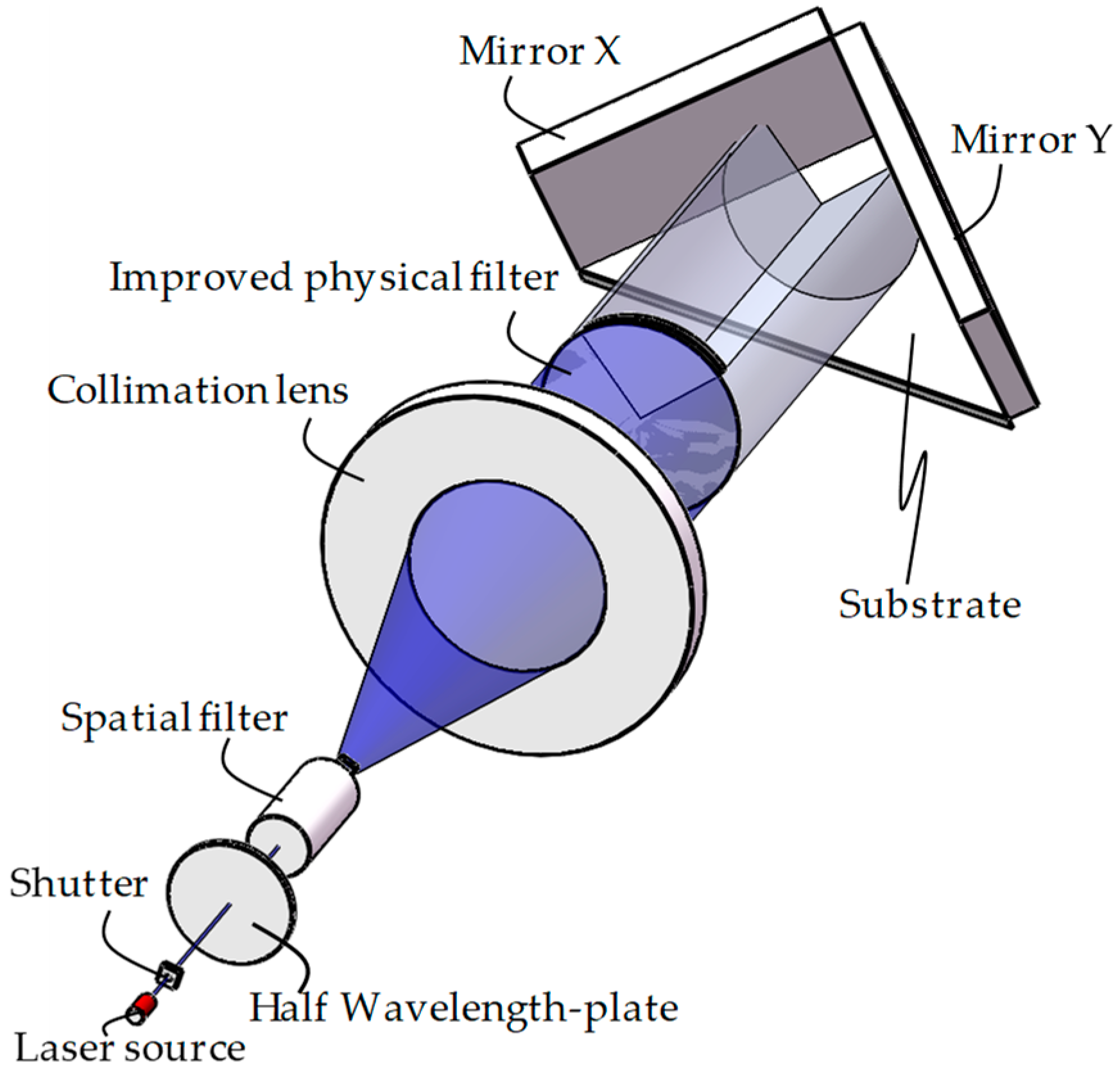
2.1. Optical Setup of the Exposure System
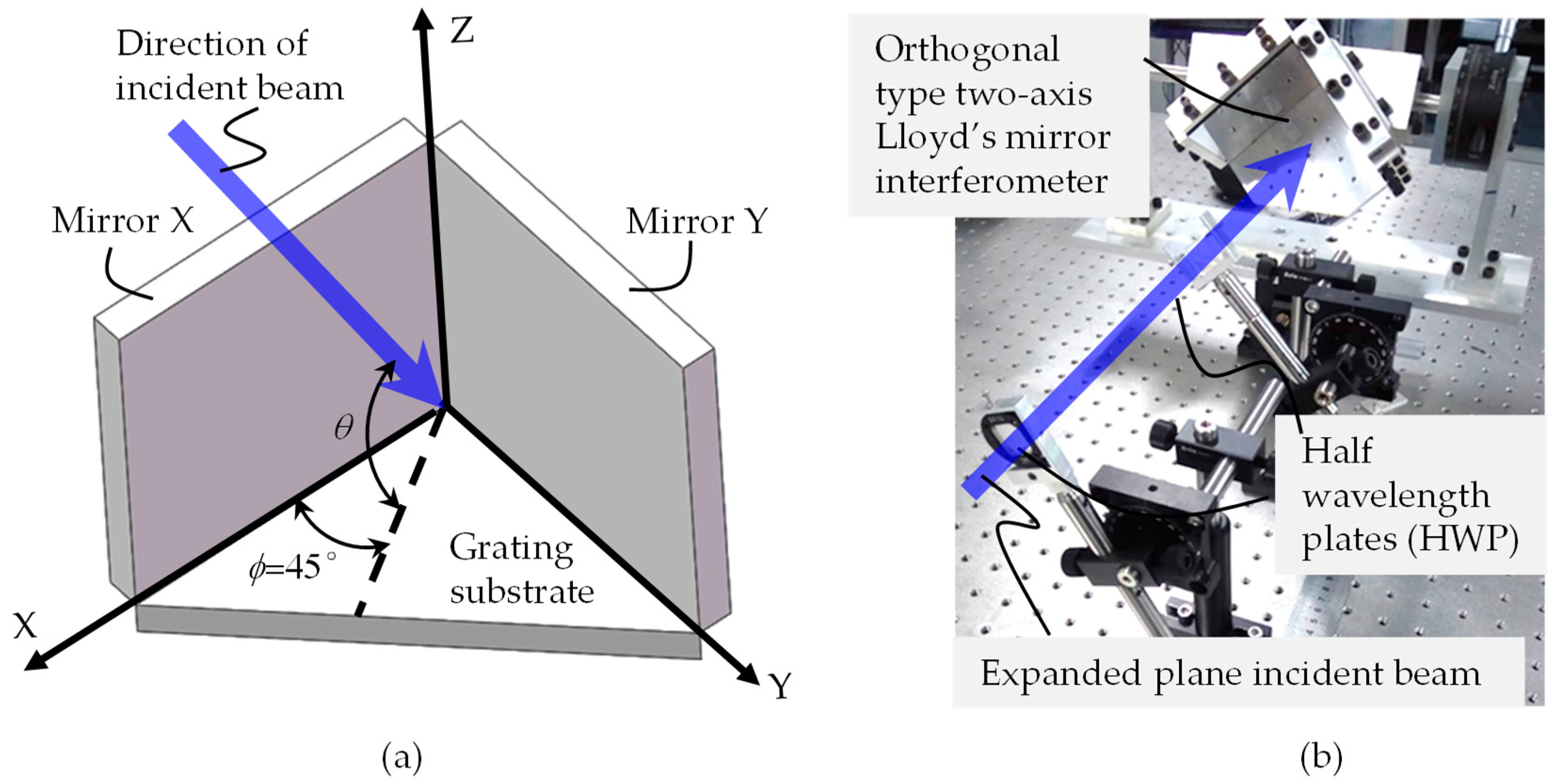
2.2. Interference Theory of Orthogonal Two-Axis Lloyd’s Mirror Interferometer
2.3. Optimum Combination of Initial Polarization
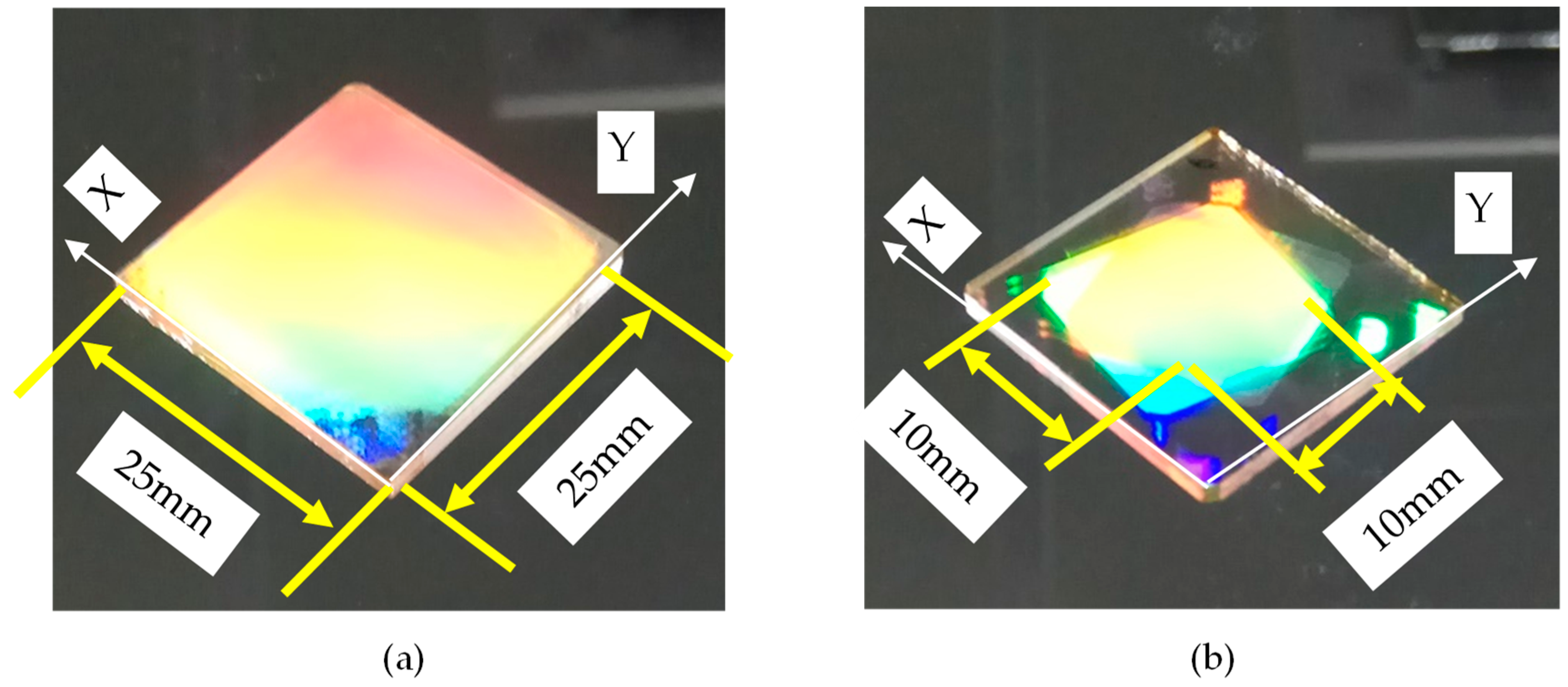
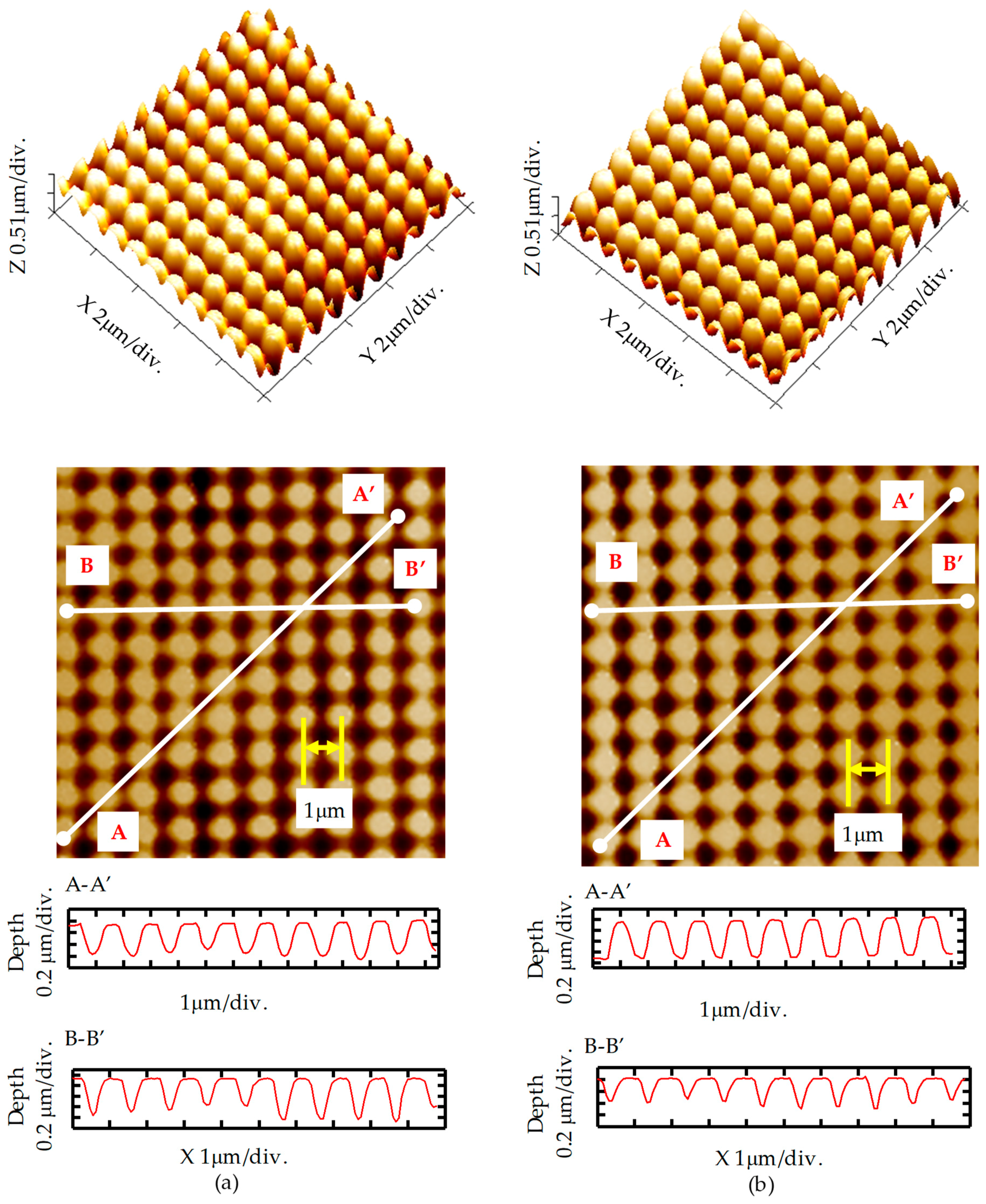
3. Experiment and Results
4. Discussion and Conclusions
Author Contributions
Funding
Conflicts of Interest
References
- Two-Coordinate Incremental Encoder PP 281R; KGM Series Catalogue; Heidenhain GmbH: Traunreut, Germany, 2018.
- Gao, W. Precision Nanometrology: Sensors and Measuring Systems for Nonmanufacturing; Springer: London, UK, 2010; ISBN 78-1-84996-253-7. [Google Scholar]
- Gao, W.; Araki, T.; Kiyono, S.; Okazaki, Y.; Yamanaka, M. Precision nano-fabrication and evaluation of a large area sinusoidal grid surface for a surface encoder. Precis. Eng. 2003, 27, 289–298. [Google Scholar] [CrossRef]
- Gao, W.; Kimura, A. A three-axis displacement sensor with nanometric resolution. Ann. CIRP 2007, 56, 529–532. [Google Scholar] [CrossRef]
- Kimura, A.; Gao, W.; Kim, W.J.; Hosono, K.; Shimizu, Y.; Shi, L.; Zeng, L.J. A sub-nanometric three-axis surface encoder with short-period planar gratings for stage motion measurement. Precis. Eng. 2012, 36, 576–585. [Google Scholar] [CrossRef]
- Lee, C.; Kim, G.; Lee, S. Design and construction of a single unit multi-function optical encoder for a six-degree-of-freedom motion error measurement in an ultraprecision linear stage. Meas. Sci. Technol. 2011, 22, 105901. [Google Scholar] [CrossRef]
- Huang, H.; Liu, C.; Jywe, W.; Wang, M.; Fang, T. Development of a three-degree-of-freedom laser linear encoder for error measurement of a high precision stage. Rev. Sci. Instrum. 2007, 78, 066103. [Google Scholar] [CrossRef] [PubMed]
- Kao, C.; Lu, S.; Shen, H.; Fan, K. Diffractive laser encoder with a grating in Littrow Configuration. Jpn. J. Appl. Phys. 2008, 47, 1833–1837. [Google Scholar] [CrossRef]
- Li, X.H.; Gao, W.; Muto, H.; Shimizu, Y.; Ito, S.; Dian, S.Y. A six-degree-of-freedom surface encoder for precision positioning of a planar motion stage. Precis. Eng. 2013, 37, 771–781. [Google Scholar] [CrossRef]
- Byun, I.J.; Kim, J.W. Cost-effective Laser interference lithography using a 405 nm AlInGaN semiconductor laser. J. Micromech. Microeng. 2010, 20, 055024. [Google Scholar] [CrossRef]
- Brueck, S.R.J. Optical and Interferometric Lithography-Nanotechnology Enablers. Proc. IEEE 2005, 93, 1704–1721. [Google Scholar] [CrossRef]
- Chua, J.K.; Murkeshan, V.M. Patterning of Two-dimensional Nanoscale Features Using Grating-based Multiple Beams Interference Lithography. Phys. Scr. 2009, 80, 015401. [Google Scholar] [CrossRef]
- Vala, M.; Homola, J. Flexible method based on four-beam interference lithography for fabrication of large areas of perfectly periodic plasmonic arrays. Opt. Express 2014, 22, 18778–18789. [Google Scholar] [CrossRef] [PubMed]
- Boor, J.D.; Geyer, N.; Gösele, U.; Schmidt, V. Three-beam interference lithography: Upgrading a Lloyd’s interferometer for single-exposure hexagonal patterning. Opt. Lett. 2009, 34, 1783–1785. [Google Scholar] [CrossRef] [PubMed]
- Li, X.H.; Gao, W.; Shimizu, Y.; Ito, S. A two-axis Lloyd’s mirror interferometer for fabrication of two-dimensional diffraction gratings. Manuf. Technol. 2014, 63, 461–464. [Google Scholar] [CrossRef]
- Zhou, H.Y.; Zeng, L.J. Method to fabricate orthogonal crossed gratings based on a dual Lloyd’s mirror interferometer. Opt. Commun. 2016, 360, 68–72. [Google Scholar] [CrossRef]
- Shimizu, Y.; Aihara, R.; Ren, Z.; Chen, Y.L.; Ito, S.; Gao, W. Influences of misalignment errors of optical components in an orthogonal two-axis Lloyd’s mirror interferometer. Opt. Express 2016, 24, 27521–27535. [Google Scholar] [CrossRef] [PubMed]
- Chen, X.G.; Ren, Z.W.; Shimizu, Y.; Chen, Y.L.; Gao, W. Optimal polarization modulation for orthogonal two-axis Lloyd’s mirror interference lithography. Opt. Express 2017, 25, 22237–22252. [Google Scholar] [CrossRef] [PubMed]
- Yun, G.; Crabtree, K.; Chipman, R.A. Three-dimensional polarization ray-tracing calculus I: Definition and diattenuation. Appl. Opt. 2011, 50, 2855–2865. [Google Scholar] [CrossRef] [PubMed]
- Chen, X.G.; Shimizu, Y.; Chen, C.; Chen, Y.L.; Gao, W. Generalized method for probing ideal initial polarization states in multi-beam Lloyd’s mirror interference lithography of 2D scale gratings. J. Vac. Sci. Technol. B 2017, 36, 021601. [Google Scholar] [CrossRef]


| Points | 1 | 2 | 3 | 4 | 5 | 6 | 7 | 8 | 9 |
|---|---|---|---|---|---|---|---|---|---|
| X + 1 | 0.21 | 0.18 | 0.17 | 0.22 | 0.19 | 0.19 | 0.22 | 0.18 | 0.18 |
| X − 1 | 0.19 | 0.16 | 0.16 | 0.21 | 0.18 | 0.18 | 0.21 | 0.17 | 0.17 |
| Y + 1 | 0.13 | 0.14 | 0.12 | 0.09 | 0.13 | 0.13 | 0.07 | 0.12 | 0.13 |
| Y − 1 | 0.13 | 0.14 | 0.13 | 0.08 | 0.13 | 0.13 | 0.06 | 0.13 | 0.13 |
| Points | I | II | III | IV | V | VI | VII | VIII | IX |
|---|---|---|---|---|---|---|---|---|---|
| X + 1 | 0.06 | 0.05 | 0.06 | 0.09 | 0.06 | 0.09 | 0.14 | 0.13 | 0.12 |
| X − 1 | 0.12 | 0.08 | 0.10 | 0.17 | 0.11 | 0.14 | 0.22 | 0.19 | 0.18 |
| Y + 1 | 0.22 | 0.23 | 0.22 | 0.12 | 0.20 | 0.17 | 0.07 | 0.13 | 0.14 |
| Y − 1 | 0.18 | 0.22 | 0.19 | 0.07 | 0.17 | 0.13 | 0.01 | 0.09 | 0.12 |
© 2018 by the authors. Licensee MDPI, Basel, Switzerland. This article is an open access article distributed under the terms and conditions of the Creative Commons Attribution (CC BY) license (http://creativecommons.org/licenses/by/4.0/).
Share and Cite
Li, X.; Lu, H.; Zhou, Q.; Wu, G.; Ni, K.; Wang, X. An Orthogonal Type Two-Axis Lloyd’s Mirror for Holographic Fabrication of Two-Dimensional Planar Scale Gratings with Large Area. Appl. Sci. 2018, 8, 2283. https://doi.org/10.3390/app8112283
Li X, Lu H, Zhou Q, Wu G, Ni K, Wang X. An Orthogonal Type Two-Axis Lloyd’s Mirror for Holographic Fabrication of Two-Dimensional Planar Scale Gratings with Large Area. Applied Sciences. 2018; 8(11):2283. https://doi.org/10.3390/app8112283
Chicago/Turabian StyleLi, Xinghui, Haiou Lu, Qian Zhou, Guanhao Wu, Kai Ni, and Xiaohao Wang. 2018. "An Orthogonal Type Two-Axis Lloyd’s Mirror for Holographic Fabrication of Two-Dimensional Planar Scale Gratings with Large Area" Applied Sciences 8, no. 11: 2283. https://doi.org/10.3390/app8112283
APA StyleLi, X., Lu, H., Zhou, Q., Wu, G., Ni, K., & Wang, X. (2018). An Orthogonal Type Two-Axis Lloyd’s Mirror for Holographic Fabrication of Two-Dimensional Planar Scale Gratings with Large Area. Applied Sciences, 8(11), 2283. https://doi.org/10.3390/app8112283