1. Introduction
The smart grid is a next generation power system [
1,
2], in which the microgrid gathers the loads, storage, and distributed energy resources (DERs) operating as a single controllable electrical power system [
3]. The microgrids’ power generation is mainly for self-consumption to decrease influence on the utility grid. With the wide adoption of renewable DC power sources, the rapid progress of power electronics technology, and the gradual increase of DC loads in commercial, industrial, and residential applications, the DC microgrid largely attracts public attention due to its merits over the AC microgrid [
4,
5]. The DC microgrid can operate in grid-connected mode and in off-grid or islanded mode if a blackout occurs in the utility grid. It can also operate as an isolated system in a remote isolated area. When operating in autonomous mode, i.e., islanded or isolated operating mode, the DC microgrid requires backup power sources to handle the intermittency of renewable energy sources. Electrochemical storage, which is commonly used to provide backup capacity and store electrical energy generated from photovoltaic (PV) panels, is provided by lead-acid battery banks because of their comparatively low cost and good performance [
6] and second life lithium-ion battery banks from electric vehicles [
7]. However, due to size and economic constraints, both the power and energy capacity of electrochemical storage are usually limited [
8]. The diesel generator (DG), based on fossil fuel or biofuel, controllable and independent of weather conditions [
9], is introduced as another backup source due to its multiple advantages [
10]. However, the slow start-up of the DG and its frequent switching on/off, which is unavoidable, require a well-conceived control method. At the same time, the DG may operate in under- or over-loading conditions. Fuel efficiency related to output power is therefore an inevitable constraint, since most DGs use fixed speed synchronous generators [
11].
In this context, several power management strategies and control methods for PV-DG-storage-based DC microgrids have been proposed. To supply the necessary power in the case of insufficient PV power and electrochemical storage power, many studies propose the DG working in either continuous operation or frequent switching. In Reference [
12], a nonlinear adaptive back-stepping controller is proposed to balance the power and stabilize the voltage of the DC bus. In Reference [
13], PV power and DG power are controlled by a linear quadratic controller. In Reference [
14], both a centralized and a decentralized demand-response multi-agent control and management system are conceived to minimize operating costs and consumers’ inconvenience concerning the electricity shortage. In Reference [
15], the pumped-storage hydroelectricity is used to store or release energy when PV and wind turbine generating power is sufficient or short; wherein if the total renewable power cannot respond to the load power demand, the DG would serve as backup power. However, DG start-up time and DG loading conditions are not considered in these articles. Otherwise, in Reference [
16], both the load-following control strategy and cycle-charging dispatch control strategy are considered and compared. Two tests using real weather data and load power demand have been carried out to validate the proposed strategies. However, the DG is emulated by a source that provides instantaneous power. Regarding the evolution of specific fuel consumption versus the specific DG generating power, Reference [
17] demonstrates that adequate power management can produce fuel cost savings compared to using only a DG, but a DGs start-up time is still not considered. In Reference [
18], optimal power management aiming to minimize both fuel costs and electrochemical storage wear costs is presented. In this strategy, the DG runs in load-following mode without demand response considerations.
Unlike in the above research work, the DG operates constantly in Reference [
19] to contribute to the power balance of an isolated DC microgrid, which includes renewable sources and electrochemical storage. To compensate power fluctuations and decrease DG fuel consumption, a discrete Fourier transform method for the coordinated power dispatch of the electrochemical storage and DG is proposed. Although the continuous operation of the DG avoids its start-up time, this operation mode results in inefficient loading and increased greenhouse gas emissions. In References [
20,
21], electrochemical storage and a supercapacitor (SC) are used to improve the performance of wind-DG generation by absorbing disturbance due to wind speed variations. However, the proposed power management strategy is based on a DG operated continually to regulate bus voltage and without considerations of fuel consumption. Moreover, a controlled DC source is used for DG behavior emulation. In Reference [
22], the DG’s frequent switching control and the non-linearity of the DG fuel consumption curve are considered, showing that significant fuel savings can be achieved compared to where the DG is used alone to supply the same load requirements. However, the sluggish dynamic response of the DG is not considered, and consequently, the given simulation results are based on an ideal power source. Furthermore, Reference [
23] considers that since the DG is equipped with an electronic speed governor and automatic voltage regulator, its dynamic behavior is not a concern and DG modelling is therefore limited to operating cost and greenhouse gas emissions.
Nonetheless, DGs cannot output instantaneous power and their cold start-up takes several seconds or even minutes [
24] before they output stable power, depending on the machine’s capacity (i.e., about 10 s for DGs smaller than 1000 kVA [
25]). Therefore, fuel-based generators need a certain warm-up period to reach a safe operating temperature and stabilize output voltage before being connected to the grid. However, power interruptions during DG start-up can cause interruption of the entire microgrid power system. Power interruptions are very costly and unacceptable to critical power consumers, such as hospitals, data centers, and security systems. Through to its rapid power response and high-power density, the SC is a solution that may solve the discontinuity problem of power supply during DG start-up. Several research works propose SC to improve dynamic characteristics and to compensate for the sluggish dynamic behavior of a variable-speed commercial DG [
11] or fixed-speed commercial DG [
26], both used as single isolated power systems. However, many SC are equipped with a passive balancing system for protective purposes, but this causes self-discharge that must be considered in long-term operation. In References [
27,
28], a power management strategy demonstrates by experiment that an SC can correctly balance DC bus power during DG start-up, although there is no consideration of DG fuel consumption and the total energy cost.
The aforementioned research work includes an as-yet not comprehensive study taking into account the various issues caused by DG and SC characteristics, in the context of an autonomous DC microgrid. To overcome all these issues, a specific power management strategy for an autonomous DC microgrid involving a DG is necessary. To advance knowledge, this article furthers research based on References [
26,
27,
28] and proposes a comprehensive power management strategy for an autonomous DC microgrid based on a PV source, electrochemical storage, a supercapacitor, and a DG. The main contribution of this paper centers on a power management strategy for an autonomous DC microgrid, and economic analysis for the DG and microgrid. This control aims to achieve power balance while accounting for the slow start-up characteristic of a DG, the self-discharge of a SC, dynamic load management, and the economic operating mode of the DG. Among the nine possible cases proposed, there are two new controls, i.e., case 6 and case 9, which have not yet been studied in the literature to the best of our knowledge. Moreover, all nine cases were experimentally proven and the results obtained confirmed the effectiveness of the proposed strategy. Moreover, these results show that dynamic load management can reduce total cost compared to a simple DG load-following mode. The study also provides a comparison between the economic operating mode and the load-following mode of the DG and demonstrates that the economic operating mode of the DG can reduce the total energy cost of the DC microgrid.
The rest of this paper is arranged as follows. Firstly, the DC microgrid system and its components are described in
Section 2. The power management strategy is introduced and analyzed in
Section 3, while experimental validation is given in
Section 4. An economic analysis is presented in
Section 5. Finally,
Section 6 gives conclusions and perspectives.
2. Autonomous DC Microgrid Configuration and Component Description
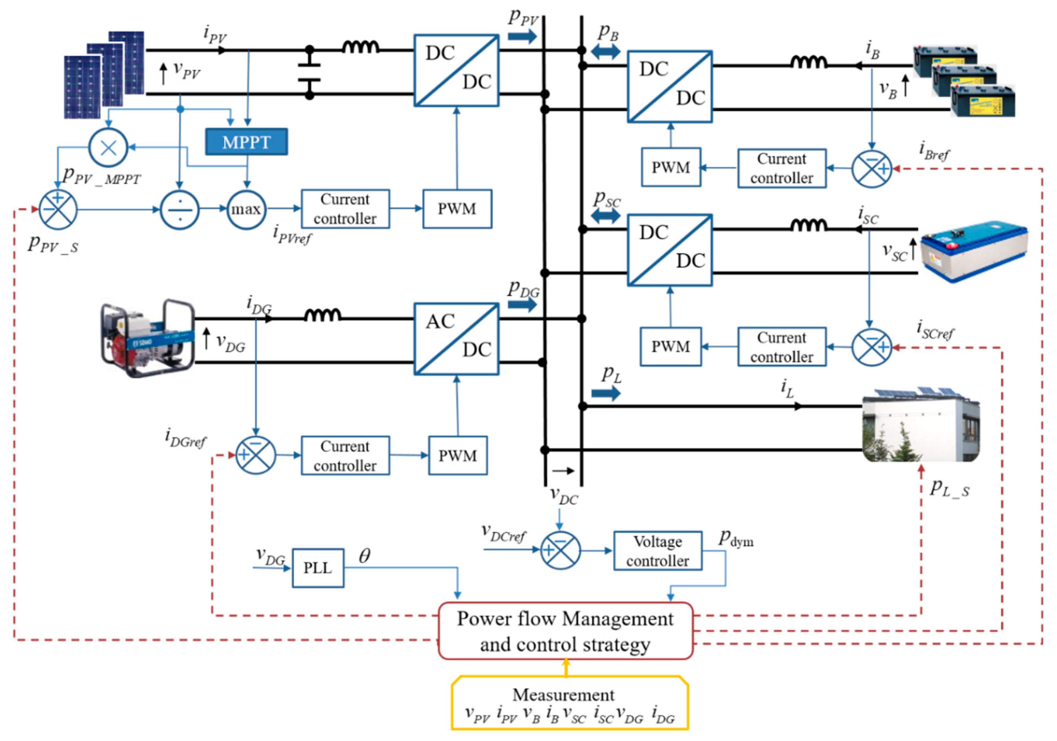
The configuration of a typical autonomous DC microgrid, which consists of a PV source, electrochemical batteries, a DG, a SC, and a DC load, is shown in
Figure 1.
In this microgrid, excepting the load, every component is connected to a common DC bus via the dedicated power converters. The DC load can be connected directly to the DC bus if its rated voltage is equal to that of the DC bus. However, in most cases, the voltages are different and so a DC-DC buck or boost converter may be involved. In addition, the AC load requires a DC-AC power inverter to change the current’s form. Considering that this paper focuses on a real-time power control and power management strategy, both the AC load and DC load are regarded as the DC power demanded on the DC bus. Furthermore, in this study, the DC load is seen as the electric appliances of a building equipped with PV panels on the roof [
29] and the microgrid controller can cut some appliances off, so that some load power
can be shed. Therefore, there is also a local load controller which can partly reduce power demand upon receiving the load shedding order from the central power management block or fault detection program. Similarly, the PV source is controlled by a maximum power point tracking (MPPT) algorithm to exploit PV energy as much as possible, but the microgrid controller can shed some PV power as
. To ensure the power balance, a voltage loop compares the instant DC bus voltage
with the reference
and obtains the power
needed to restore the rated voltage of the bus. The power flow management and control strategy will then transform this power into different current references (
,
, and
), and then distribute them to the controller of each source. DC bus voltage fluctuations are considered to verify system stability. The control of each source is carried out by a control loop including the classic proportional and integral regulator and the PWM controller. In particular, a Phase-Locked Loop (PLL) is needed to control DG power, calculating the electrical rotation angle
from the DG AC voltage
. The bandwidth of each control loop is carefully chosen to avoid stability issues. In fact, all these controls are implemented in a single central digital signal processor controller in the experimental platform.
2.1. Diesel Generator Electric Modelling
As mentioned in
Section 1, the DG used in this study is supposed to be at a constant speed with its speed regulator system, which ensures the frequency of 50 Hz. It is mechanically coupled to a single-phase brushless synchronous generator, which has a closed loop automatic voltage regulator to keep AC voltage at 230 V and frequency at 50 Hz. These two control systems are assembled and installed inside the DG to provide a relatively fixed AC output voltage, which is independent of output current or load impedance. The DG can therefore be viewed as an independent voltage source. When the voltage amplitude
and frequency
satisfy Equation (1), a switch is closed to output the DG power into the bus of the DC microgrid.
2.2. Supercapacitor Modelling
The SC has a high-power density characteristic, which allows it to release a great amount of power instantly [
30], but its energy capacity is relatively low. In general, there is no power constraint and SC power
can be positive and negative, which represent discharging power to the DC bus and absorbing power from the DC bus, respectively. Although the SC is made up of many capacitor cells connected in series and parallel, it can be seen as a single capacitor. Therefore, the SC energy
, depends on the SC voltage
and the SC capacitance
as given in Equation (2):
where
is the electric charge stored in the SC.
Hence, the state of charge of the SC, noted
, can be calculated as in Equation (3):
where
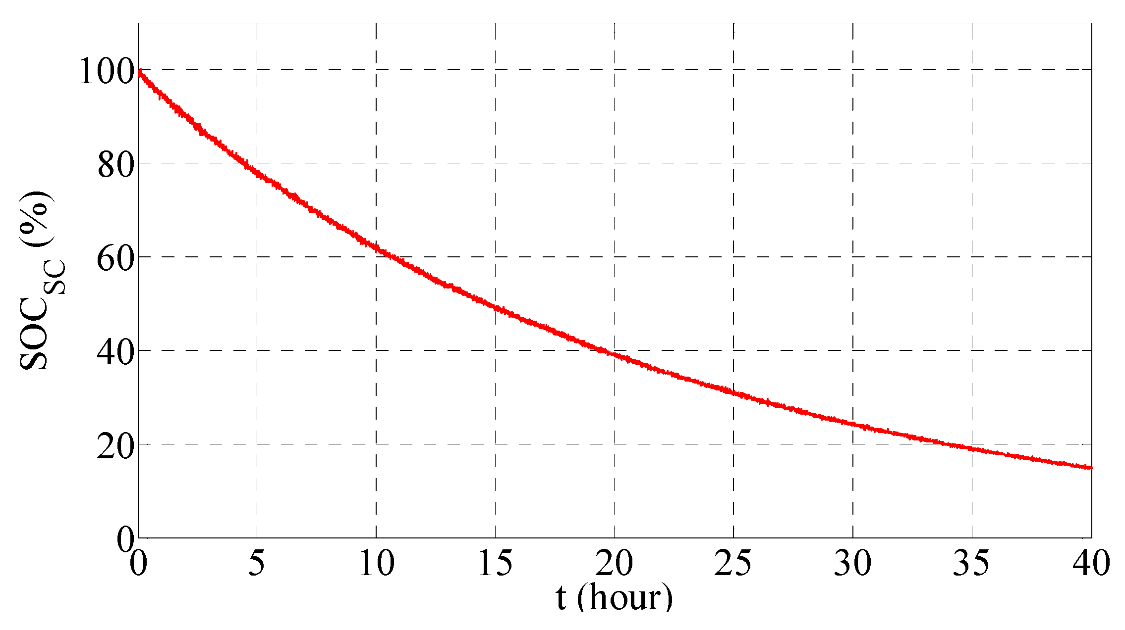
is the SC’s rated voltage. In addition, it should be noted that as, in general, the studied SC has a self-discharging nature due to its resistive cell balancing,
may decrease from 100% to 15% in about 40 h, as shown in
Figure 2 [
27].
Citing this self-discharging nature and given that the SC has to cover DG start-up, there are four definitions on the constraints of the SC’s state of charge: , , , and , which are explained one by one as follows.
- (1)
and define a range in which the SC is considered fully recharged. This is for the purpose of avoiding frequent SC recharging caused by the self-discharging property. At each recharge, the SC is recharged until arrives at , and then the SC is not recharged again unless decreases below .
- (2)
Symmetrically, and define a range in which the SC is considered to be empty. While is the lower limit of , indicates that the SC still has enough energy to support the whole system alone during DG start-up. As such, the SC must be recharged if falls to due to self-discharging, and in such cases, the recharging power can be so weak that self-discharging is merely compensated.
Thus, the SC should always have enough energy for DG start-up when there is not enough stored energy in electrochemical batteries. Therefore, as below becomes prohibited, when reaches this value, the SC is recharged like a load; the recharging power is equal to the self-discharging power, so that the SC’s stored energy is maintained until the DG needs starting.
By keeping between the four critical values, SC should always have enough energy to maintain the microgrid power balance during the start-up of DG.
2.3. PV Source Control Methods
In general, a MPPT method is implemented to maximize the output power of the PV source [
31,
32]. However, PV production should be limited via a constrained algorithm to prevent the electrochemical battery bank from being overcharged. PV power production
is thus described as:
where
is the MPPT PV power reference and
is the PV shed power reference, i.e.,
is the PV limited power reference. The adopted MPPT control is based on the Perturb and Observe method from Reference [
31]. The implemented PV limited power control is completely detailed in Reference [
33].
2.4. Electrochemical Battery Bank Modelling
As an essential component of the autonomous microgrid, the electrochemical battery bank is used to guarantee the stable operation of the whole system by supporting the intermittent renewable energy source and absorbing excess power not used by the load. Like the inherent properties of the battery, the recharging and discharging power of the battery bank should still be constrained to slow down battery aging, as in the following equation.
where
is the power drawn from or injected into the battery bank. Since battery bank discharging power is defined as positive, and recharging power as negative, in this work, the discharging limit
and recharging limit
are positive and negative, respectively. Moreover, to protect the battery bank from over-charging and over-discharging, the state of charge of the battery bank, noted as
, should be kept within a certain range. It can be expressed as given in Equation (6):
where
and
are the upper and lower limitation, respectively. The
value at time
depends on the
value at time
, and the energy absorbed or released by the battery bank during the time period
. It can be expressed as follows:
where
is the total capacity in Ah of the electrochemical battery bank and
is the voltage of the electrochemical battery bank.
2.5. Load-Shedding Calculation
The main objective of the electrical power system is to satisfy load power demand. However, the load-shedding case may occur when the power demand is temporarily superior to the power supply. Some non-critical electrical appliances of a building can thus be shut down briefly and be restarted later. Hence, the load power
is described as in Equation (8):
where
is the load power demand and
is the load shed power reference.
3. Power Management Strategy
In the microgrid system, both PV power
and load power
are randomly variable, but PV power can be limited, and load power can be shed if needed. Conversely, electrochemical battery bank power
, DG power
, and SC power
are the controllable elements within their own physical limits. The control law of power balancing must thus be completely respected at any time according to the following equation:
where
is the DC bus capacitor and
is the DC bus voltage.
To achieve real-time control, an algorithm should be designed to arrange the power system elements in a specified sequence. This algorithm should assign power references to each source and give power-shedding references for the PV source and the load. The algorithm must also comply with the power balance equation, the predefined priority order of the components to operate in the DC microgrid, and the limitations imposed. The PV source has the first priority to supply the load. Accordingly, the electrochemical battery bank is essential to ensure stable operation of the whole system due to the intermittence of PV generation. Otherwise, when
decreases to its lower limit or the necessary power is greater than
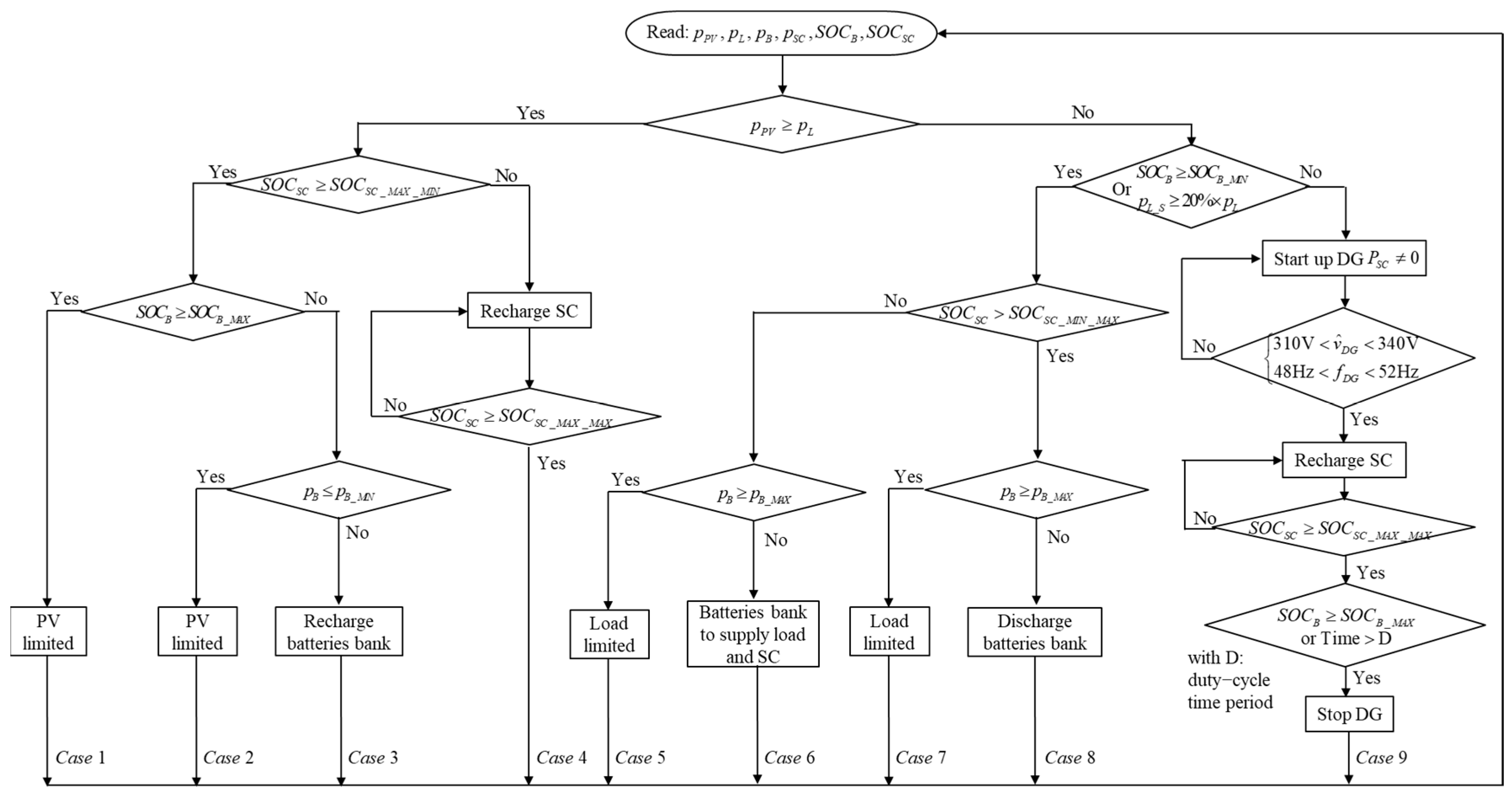
, the DG operates to supply the load and also to recharge both storage units: the electrochemical one and the electrostatic one. Nevertheless, the DG needs some time to start up and cannot immediately offer the power needed. Therefore, the SC is used to compensate the power deficiency during DG start-up, i.e., the SC and the DG are unified as a backup source to supply the DC bus. The SC must always have enough energy to supply the whole DC microgrid during the start-up phase of the DG. Resultantly, the priority of the SC is higher than that of battery bank in the recharging sequence, so excess power is preferentially injected into the SC. To describe the overall power management strategy,
Figure 3 represents the power system control algorithm flowchart and its nine possible power flow cases.
3.1. Case 1, 2, 3, 4
When PV power is greater than user demand, there is excess PV power after fully supplying the load.
If both the SC and the battery bank are fully recharged, PV power is limited to only supplying the load and stabilizing the DC bus, and the system operates as given in case 1 of
Figure 3. If the electrochemical battery bank is not full, excess PV power is injected into the battery bank. However, if the excess PV power is greater than the battery bank’s maximal recharging power, PV power is limited to supplying only the load and the battery bank’s maximal recharging power and the system works as given in case 2. Otherwise, PV power is not limited and the system runs as given in case 3. Conversely, if the SC is not in its saturation state, i.e.,
, then excess power will first be injected into the SC until
reaches
and the system will operate as given in case 4.
3.2. Case 5, 6, 7, 8, 9
If there is not enough PV power to meet load demand, other sources are required to complement the deficient power.
The electrochemical battery bank is set to provide the energy in the first place. Simultaneously, the energy in the SC decreases on account of self-discharging as time goes by. The SC could therefore be empty before the battery bank energy is depleted. As the SC is essential for DG start-up, draining of SC energy should be avoided. Hence, when
reaches
, the electrochemical battery bank should provide additional power to compensate the self-discharging power of the SC, so that the start-up of the DG can always be supported by SC power. Consequently, the role of the battery bank is not only to supply the load, but also to recharge the SC. Nevertheless, it is possible that the required power could be greater than the electrochemical battery bank’s maximal discharging power, so the load power is limited and the system is driven as given in case 5 of
Figure 3. Otherwise, the electrochemical battery bank’s power is enough, corresponding to case 6. On the other hand, if
is greater than
, the electrochemical battery bank only supplies load demand. There are also two branches depending on whether or not electrochemical battery bank power is insufficient, represented by the cases 7 and 8, respectively.
The last scenario is the case 9, where, in the case of insufficient PV power, the parallel supply mode of the PV and DG power sources is considered. During the duty-cycle noted D, the DG supplies power in parallel with the PV source. Once the PV source and storage can satisfy load power demand or the duty-cycle time is ended, the DG is stopped to save fuel and reduce greenhouse gas emissions. To start up the DG, there are two conditions that can be met. If either is met, the DG will be started up. The first condition is that load power-shedding demand is more than 20% of total load power demand. The second is that reaches its lower limit. During the period of DG start-up, the SC is used to stabilize DC bus voltage and balance the DC bus power for a short period. When the DG reaches its stabilized output state, it will be connected to the DC bus. The DG then operates not only to compensate the shortage of PV power, but also to recharge the two storage units, the electrochemical battery bank, and the SC. In this case, the power reference of the DG is set to be the sum of the maximal battery bank recharging power and the difference between PV power and load power. According to the recharging priority, the SC is first recharged to , and then all excess power is injected into the electrochemical battery bank. The DG will then be stopped if either of the following conditions is met: (i) The electrochemical battery bank is fully recharged; or (ii) The DG has run for more than the chosen duty-cycle time period. The maximal running time limitation is for economic purposes. A short limit can save fuel but may lead to frequent start-up of the DG as the battery bank is not fully recharged, which can reduce DG lifespan. For a small-scale power DG, the duty-cycle time period has to be determined as a good trade-off between fuel consumption and start-up frequency. Case 9 is the only case in which the DG is started and stopped.
4. Experimental Tests
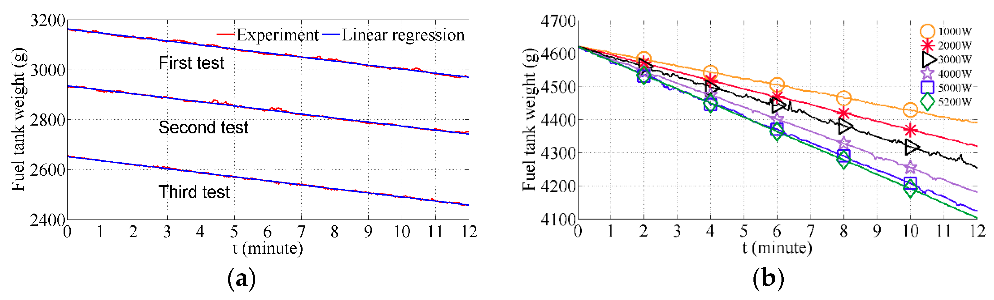
Three tests of the proposed power management system are carried out over three different weather profiles, making it possible to show all nine possible cases. To compare fuel cost and fuel consumption with the power management strategy presented in Reference [
27], in which the DG cost is not considered, case 9 presented in
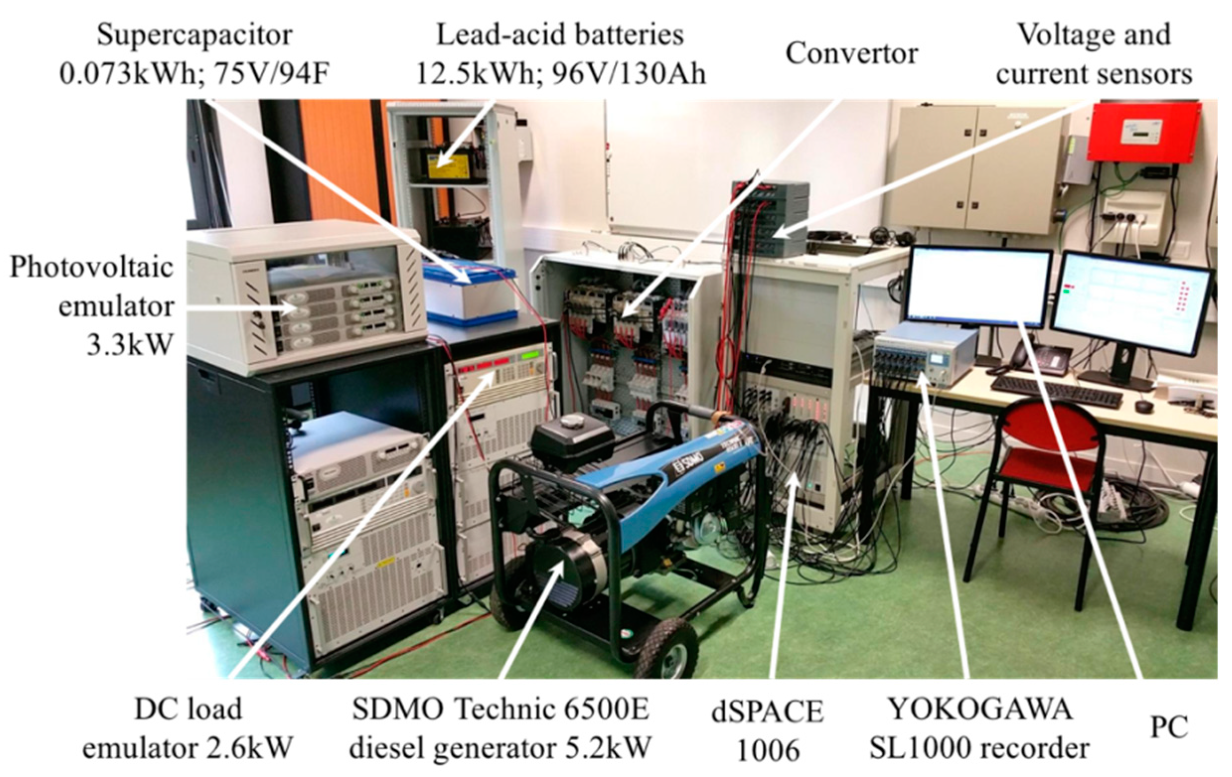
Figure 3 is changed to a simple load-following mode, i.e., producing the same amount of power as load demand, while not recharging the electrochemical battery bank and the SC. To simplify this comparison, a PV source emulator following three real MPPT generation profiles is used instead of a real PV system; these profiles were recorded at Compiègne in France during our previous work. Moreover, it is notable that a simple and arbitrary load power demand profile is considered in this study. To illustrate and prove the effectiveness of the proposed power management strategy, an experimental platform is set up, as illustrated in
Figure 4.
All the algorithms were programmed in MATLAB/Simulink and implemented in the dSPACE 1006 real-time control system. The rated DC bus voltage was chosen as 400 V according to Reference [
29]. Regarding the SC self-discharging, the average self-discharging current was fitted to be 0.03 A, according to the curve given in
Figure 2. The parameters of the DC microgrid components, of which more details can be found in the published paper [
27], are listed in
Table 1, and the considered values of imposed constraints are given in
Table 2. Each DC source is connected to a DC/DC reversible Boost converter so as to interface with the 400 V DC bus, and the DG is connected to an active full bridge rectifier. All the converters are commanded by a classical PWM controller at a frequency of 12 kHz.
In addition, it was assumed that 20% of load power is non-critical and can be shed and the other 80% is uninterruptable and its supply should be guaranteed by the DG. Regarding the DG, a one-hour duty-cycle was proposed as a good trade-off between fuel consumption and start-up frequency. Given that the electrochemical battery bank’s capacity was too great for the power level of the installed system, in order to observe all the cases, was limited to within a narrow range. Similarly, the electrochemical battery bank’s power was limited at the same power level as the PV source. In addition, SC power was not limited, but the same amount of power could cause great current in the case of low SC voltage, which can be harmful to the experimental equipment. Thus, the lower bound of was limited to a minimum of 45%, since it was quadratically proportional to the SC voltage.
Depending on the weather day profile, the three chosen days represented three types of solar irradiance: Mixed high irradiance with strong fluctuations and low solar irradiance without fluctuations (Test 1, 8 July 2016); high solar irradiance with strong fluctuations (Test 2, 9 July 2016); and high solar irradiance almost without fluctuations (Test 3, 10 July 2016).
4.1. Test 1
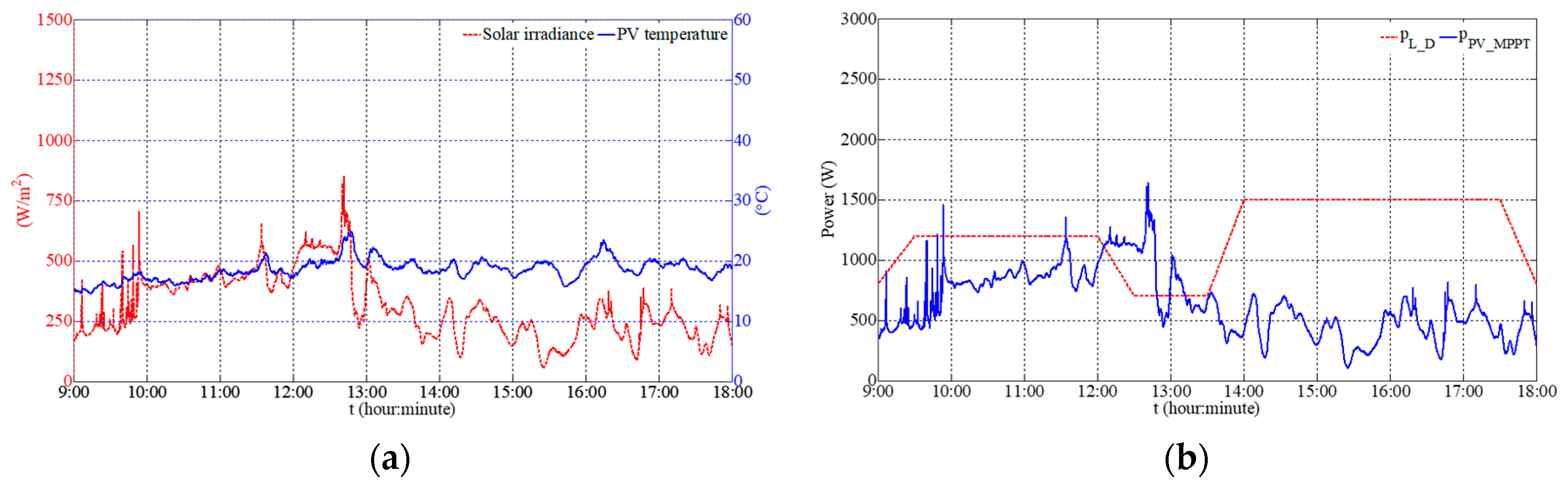
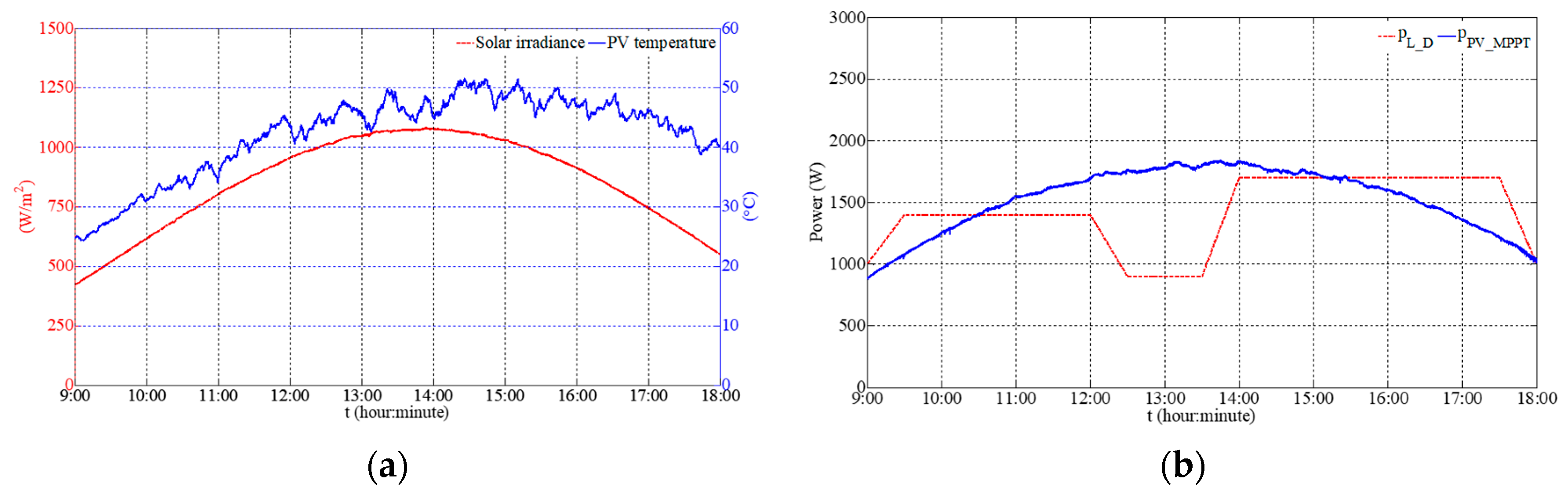
The solar irradiance and the PV cell temperature of the first test are profiled in
Figure 5a.
As this figure shows, irradiance was under 400 W/m
2 most of the time, i.e., overcast weather. PV MPPT power was therefore far less than load power demand, which can be seen from
Figure 5b. In this weather and under this load profile, two experiments were carried out depending on the DG operating mode, i.e., duty-cycle mode and load-following mode.
4.1.1. DG Duty-Cycle Mode
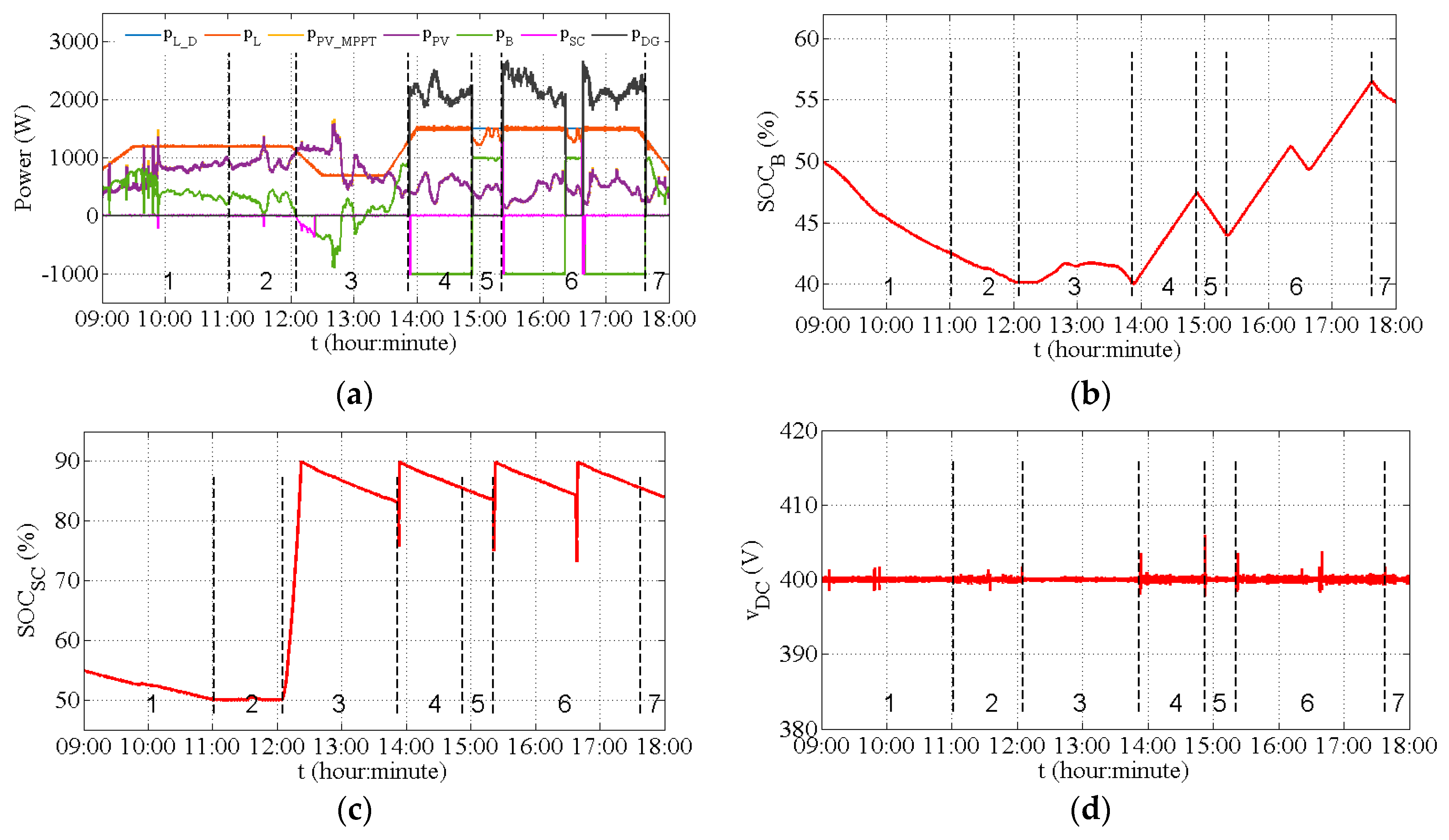
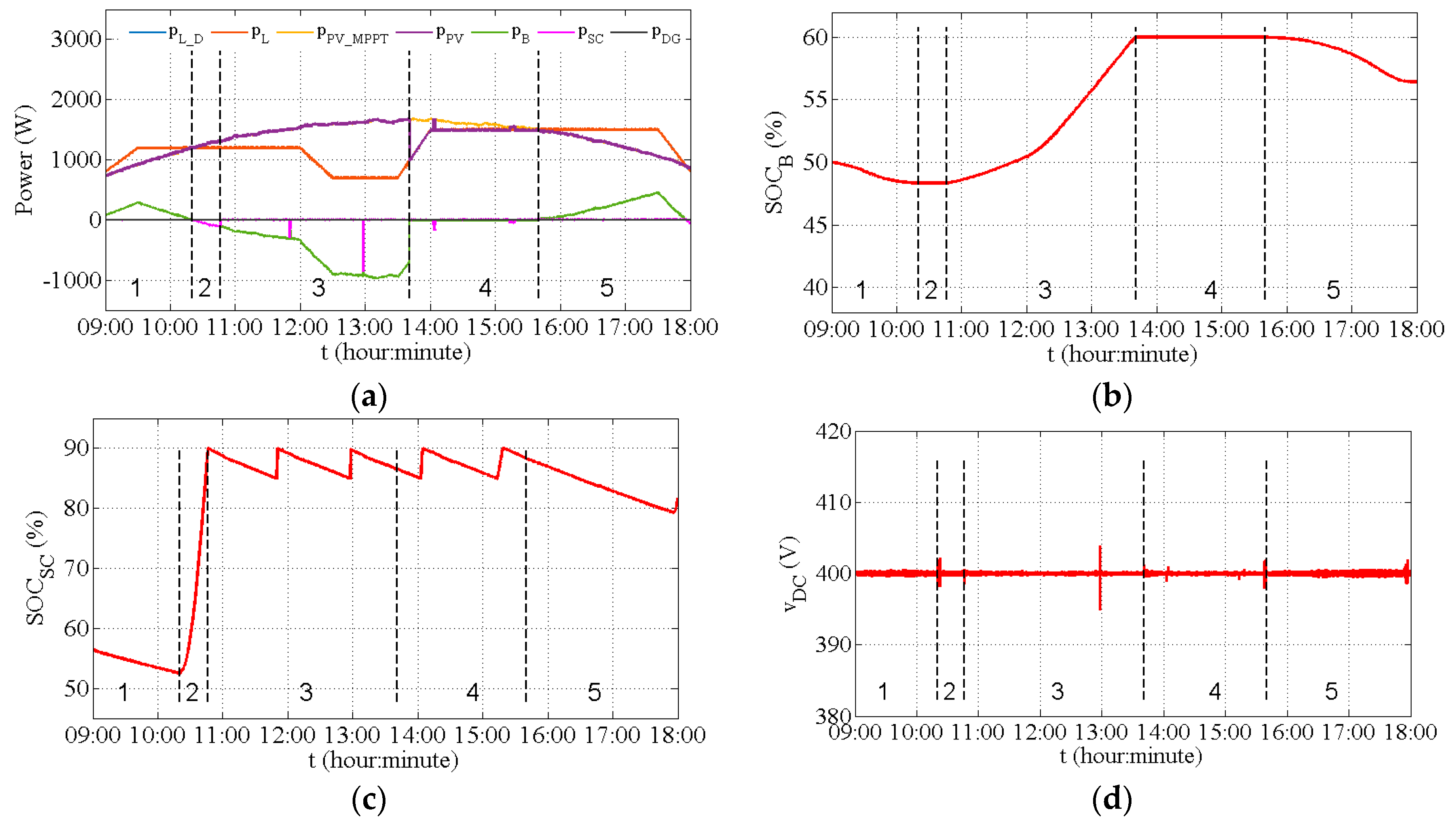
In duty-cycle mode, DG power was set to be the sum of the maximal battery bank recharging power and the difference between PV power and load power when the DG was started.
Figure 6a shows the DC microgrid power evolutions during the nine hours. During the first interval (
), the electrochemical battery bank and PV source are the active suppliers (case 8). As time goes on, the energy stored in the SC decreases through self-discharging until reaching the constraint. Thus, during the second interval (
), the electrochemical battery bank not only supplies the load, but also gives some power to the SC to maintain the energy level stored in the SC. This represents the case 6 given in
Figure 3. Then, in the third interval (
), there is excess PV power, which is preferentially recharged into the SC. This represents the case 4 given in
Figure 3. At around
, the SC is full. In the next interval (
), the energy of the battery bank is first used up.
reaches its lower limit and then the SC supplies the load during DG start-up. Once the DG can offer stable power, the excess power first recharges the SC. Afterwards, the electrochemical battery bank begins to absorb power when the SC is fully recharged. The DG is then stopped after one hour. This represents the case 9 given in
Figure 3. In the fifth interval (
), the deficient power is greater than the electrochemical battery bank’s maximal discharging power and so load-shedding takes place. This represents the case 7 given in
Figure 3. In the sixth interval (
), around
and
, the DG is started up twice because load-shedding demand is more than 20% of total power demand. This represents the case 9 given in
Figure 3. In the last interval (
), only the battery bank supplies the deficient power. This represents the case 8 given in
Figure 3.
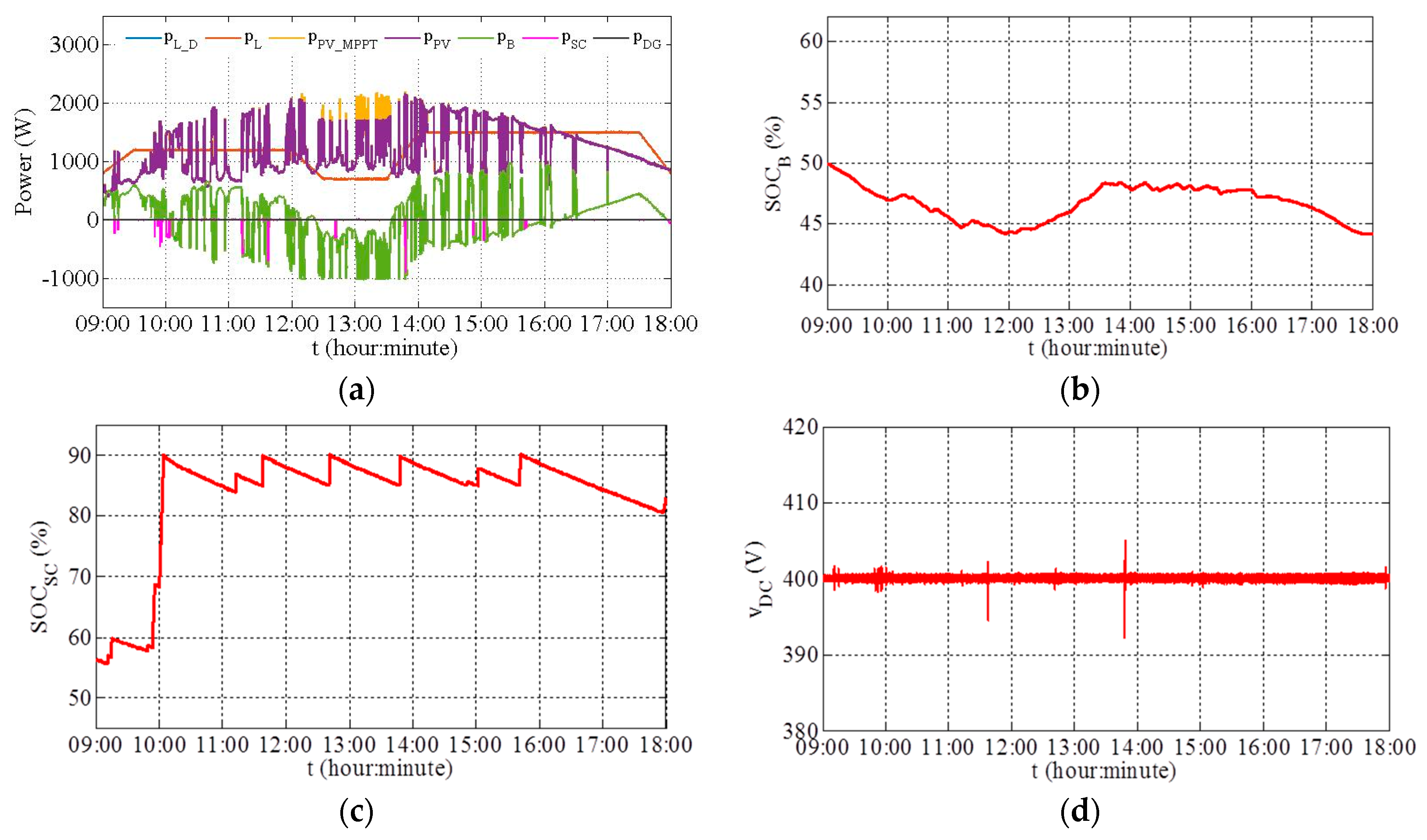
Figure 6b,c show
and
evolutions, reflecting the fact that the electrochemical battery bank and SC run well for providing and absorbing energy within their respective restrictions. Considering that the goal of this nine-hour experiment was to verify the feasibility of the proposed strategy with a real PV power profile, the experimental results showed that the power was well balanced and the DC bus voltage was stable with acceptable fluctuations (the maximum fluctuation amplitude is within ±1.5% of the rated voltage equal to 400 V), as shown in
Figure 6d.
4.1.2. DG Load-Following Mode
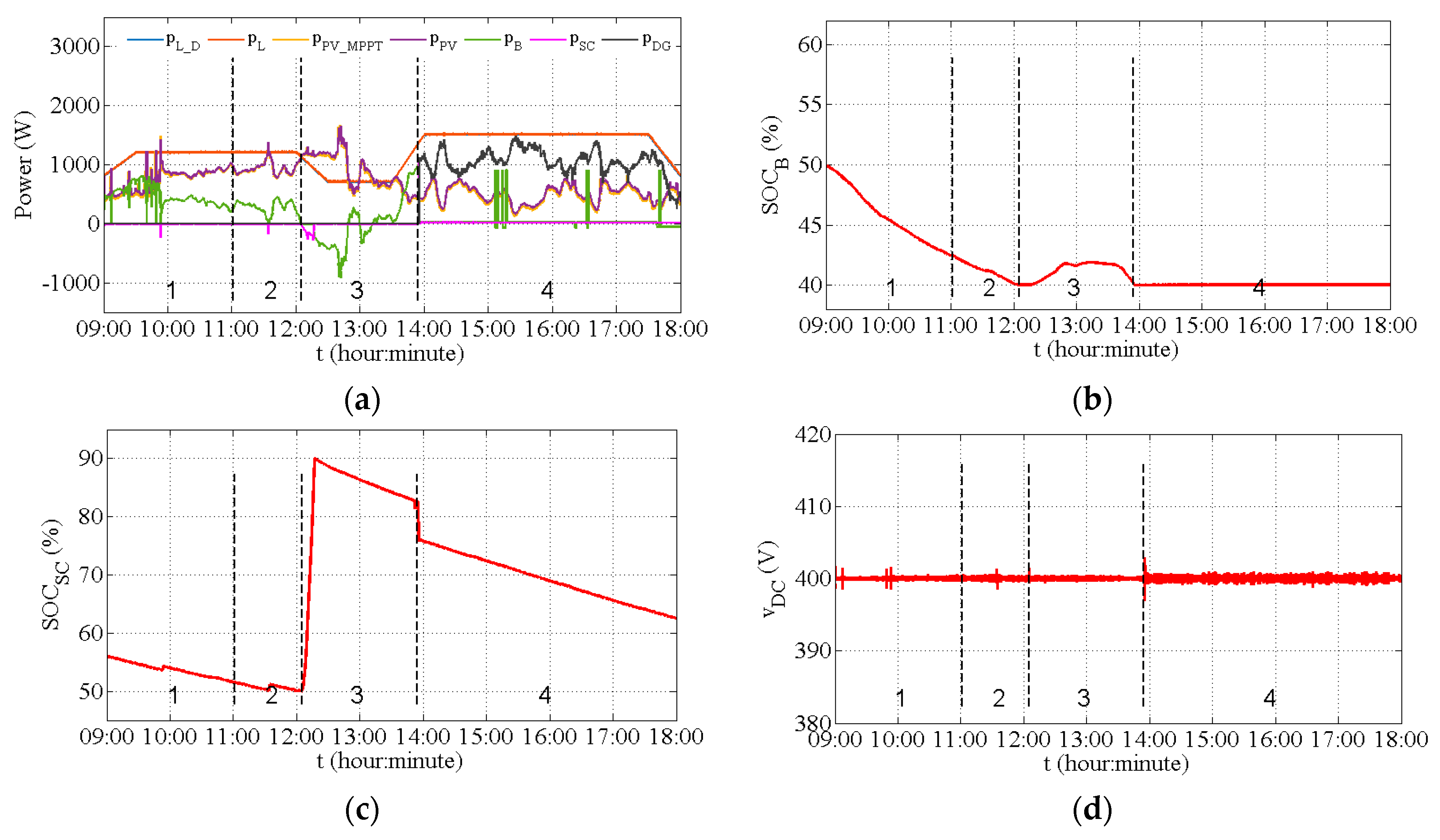
In load-following mode, the reference of the DG generating power was given as the deficient power, meaning that it only satisfies load demand. There was no consideration of the DG power cost, and there was no excess power to recharge the SC and electrochemical battery bank. Experimental results are shown in
Figure 7.
Figure 7a shows that, before the DG is started up, the power evolution of each component is similar to that given in
Figure 6a. In the fourth interval (
), DG output power is just enough to avoid load-shedding, while the SC and battery bank are not charged.
Figure 7b,c show
and
evolutions, which are well within their respective ranges. Since there is no DG power to recharge the SC and electrochemical battery bank in the fourth interval,
remains in the empty state and
is in continuous decline. The DC bus voltage is also steady within a ±1.5% fluctuation amplitude of the rated voltage, as shown in
Figure 7d.
For both operating modes of the DG, the parallel supplying mode of the PV and DG power sources is considered in case of insufficient PV power.
Figure 6a and
Figure 7a show that the DG supplies power in parallel with the PV source until the duty-cycle time ends or the PV source and storage can satisfy the load power demand.
4.2. Test 2
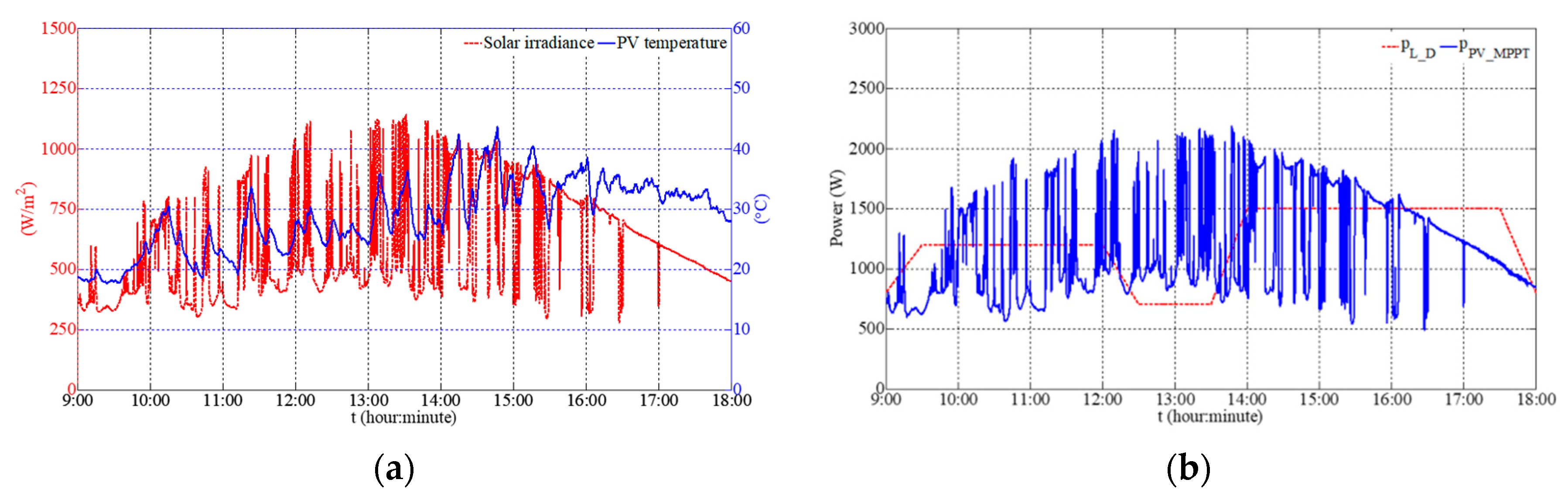
The solar irradiance and the PV cell temperature are profiled in
Figure 8a. It is clear that the solar irradiance fluctuates fiercely and frequently, causing strong PV power fluctuations as shown in
Figure 8b.
Figure 9a demonstrates that at noon, excess PV power goes beyond
, while PV power is limited afterwards. This is case 2. The SC is recharged several times while the electrochemical battery bank absorbs and discharges power dynamically.
Figure 9b,c show that both
and
have respected their dedicated restrictions. Since PV power fluctuates severely and frequently, DC bus voltage remains within a ±2% fluctuation amplitude of the rated DC bus voltage, as shown in
Figure 9d. The DG is not used because PV power is quite sufficient.
4.3. Test 3
Figure 10a presents the profiles from test 3. Visibly, it is a perfect sunny day with almost no fluctuations: Most of the time, irradiance is greater than 700 W/m
2. Therefore, PV power is greater than load demand most of the time, as depicted in
Figure 10b.
During the first interval (
),
Figure 11a shows the electrochemical battery bank and PV supply power (case 8). During the second interval (
), the SC is recharging with excess PV power. This corresponds to case 4 given in
Figure 3.
At around
, the SC is full. Afterwards, in the third interval (
), the electrochemical battery bank begins to absorb power. This corresponds to case 3 given in
Figure 3. During this interval, around
and
, the SC is again recharged when
is below the value
and when there is excess PV power. This corresponds to case 4 given in
Figure 3. In the next interval (
), after the electrochemical battery bank is fully charged, the PV power limited control is executed to supply the load and the SC when
falls below
at around
and
. In the last interval (
), the electrochemical battery bank supplies the deficient power. This corresponds to the case 8 given in
Figure 3.
Figure 11b,c show that
and
evolutions always remain within the constrained range. The DC bus voltage shown in
Figure 11d is quite stable within a ±1.5% fluctuation amplitude of the rated DC bus voltage. The different DG operation modes are not compared in this test, because there is no need for DG power on this day.
6. Conclusions
In this paper, a specific power management strategy was proposed for an autonomous DC microgrid using a DG as a backup source and a SC as compensatory power to compensate the DG’s sluggish behavior. To overcome its self-discharging property, the SC was regularly recharged by the other sources with a higher priority than the electrochemical battery bank. In particular, once the DG starts outputting power, the SC is recharged before recharging the electrochemical battery bank. SC energy is thus always kept above a certain level to supply the whole system during the start-up of the DG. The proposed strategy was experimentally proven to be able to maintain the power balance and consider the slow start-up that is characteristic of the DG, the self-discharge of the SC, dynamic load management, and the economic operating mode of the DG.
In addition, an economic analysis method was presented for determining the DG operation cost. The experimental results showed that the duty-cycle operating mode can reduce the energy cost for both the DG itself and the whole microgrid, in comparison with the load-following mode studied in the previous research.
Further energy cost savings can be expected through adoption of an appropriate duty-cycle time of the DG. The choice can be made using either optimization methods or simply in an empirical method. To clearly formulate an optimization problem, the PV and load powers forecasting for the day ahead, as well as for intraday, should be integrated. Future work will focus on the optimization problem.


