Foot-Mounted Inertial Measurement Units-Based Device for Ankle Rehabilitation


Abstract
1. Introduction
- Grade l: Involves the stretching of any ligament without tearing and slight signs of pain and/or inflammation.
- Grade II: Involves the partial tearing of one or more ligaments and moderate pain and inflammatory signs.
- Grade III: Involves full tear of ligaments and joint instability; pain and inflammatory signs are significant, and there is a loss of ankle function and mobility.
2. Materials and Methods
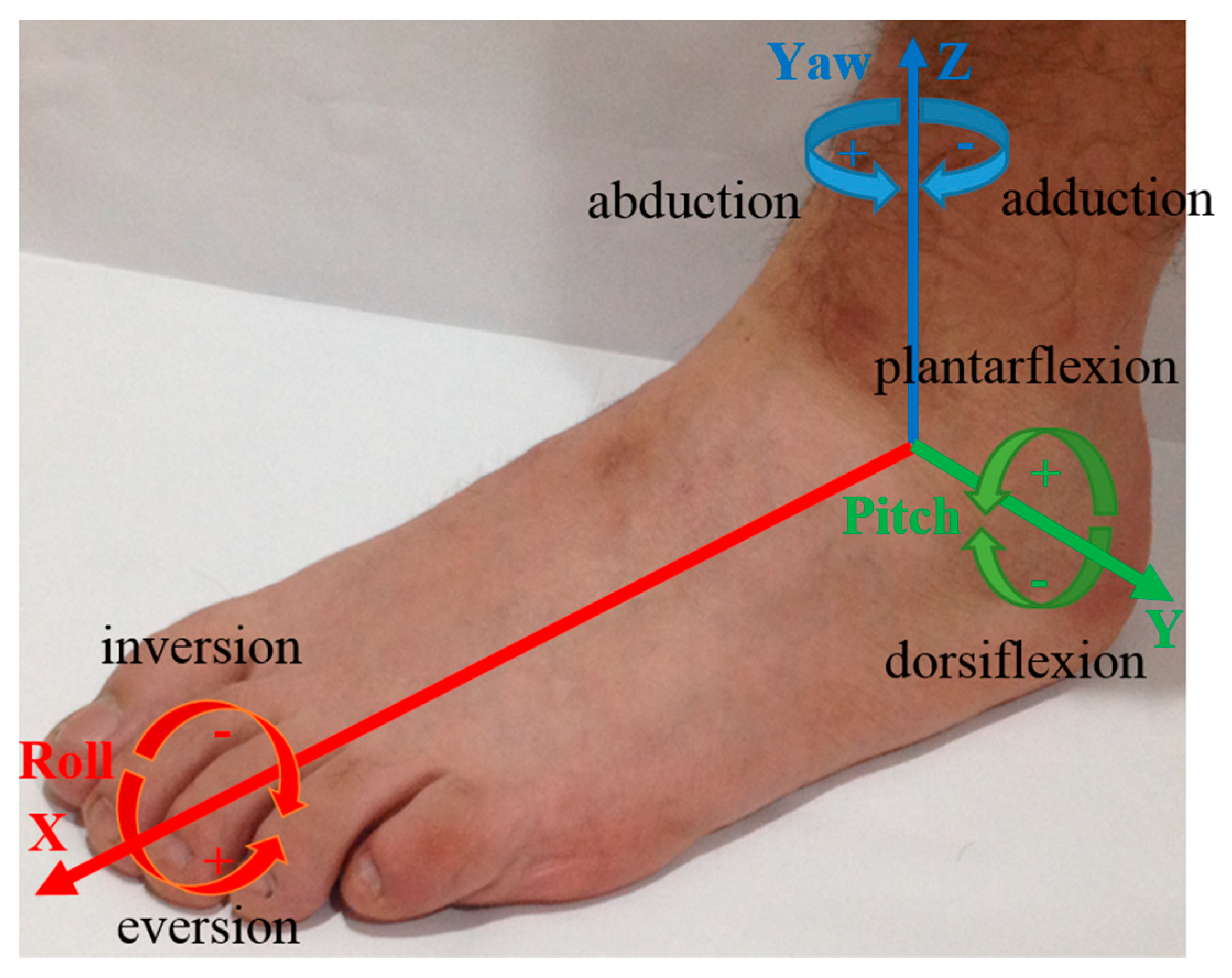
2.1. Inertial Sensor
2.1.1. Inertial Measurement Units
2.1.2. Estimation of the Inertial Measurement Variable
3. Foot Attitude Biofeedback Device
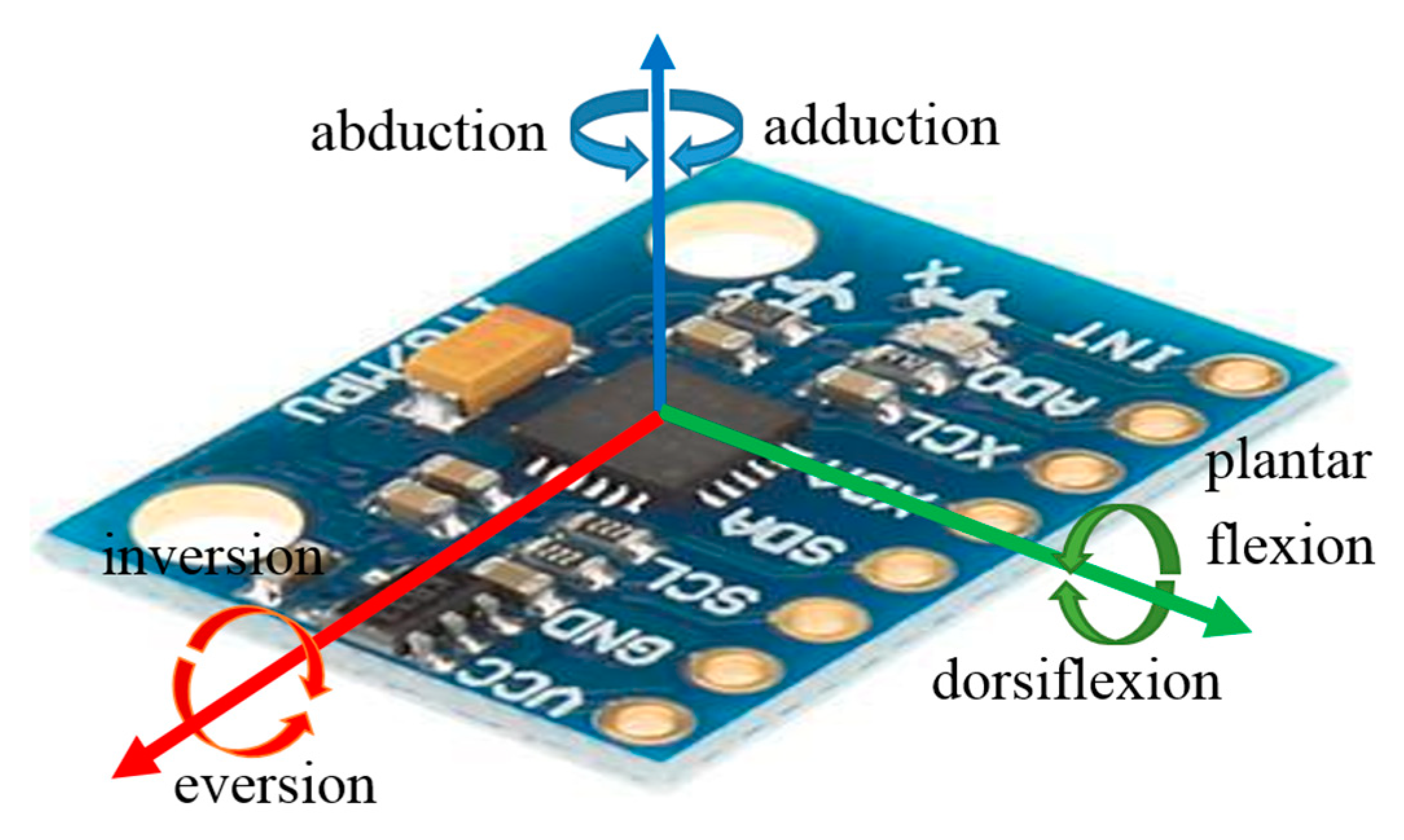
3.1. MPU-6050
3.2. Libraries for the MPU-6050
3.3. Calibration
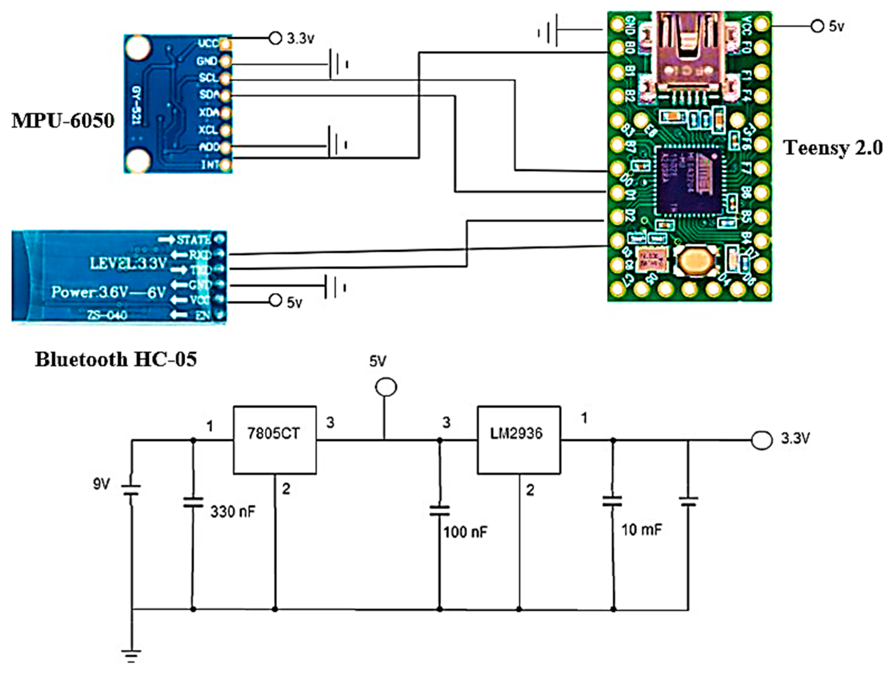
3.4. Connections
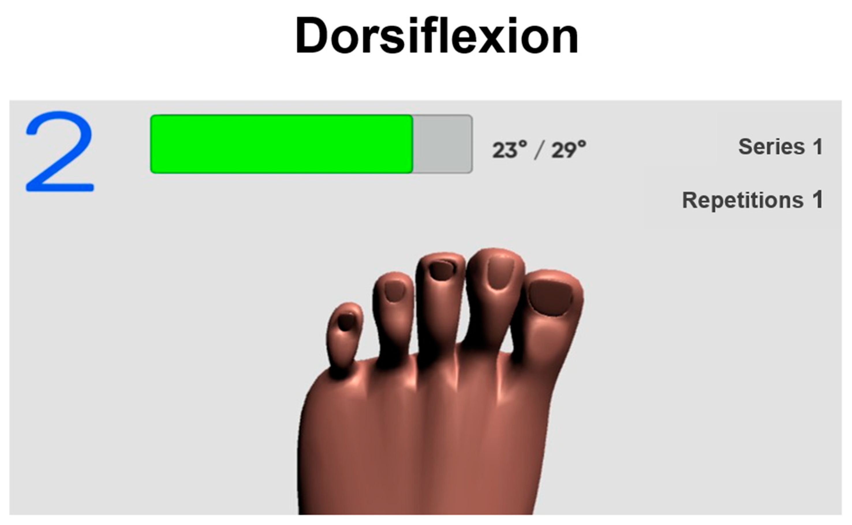
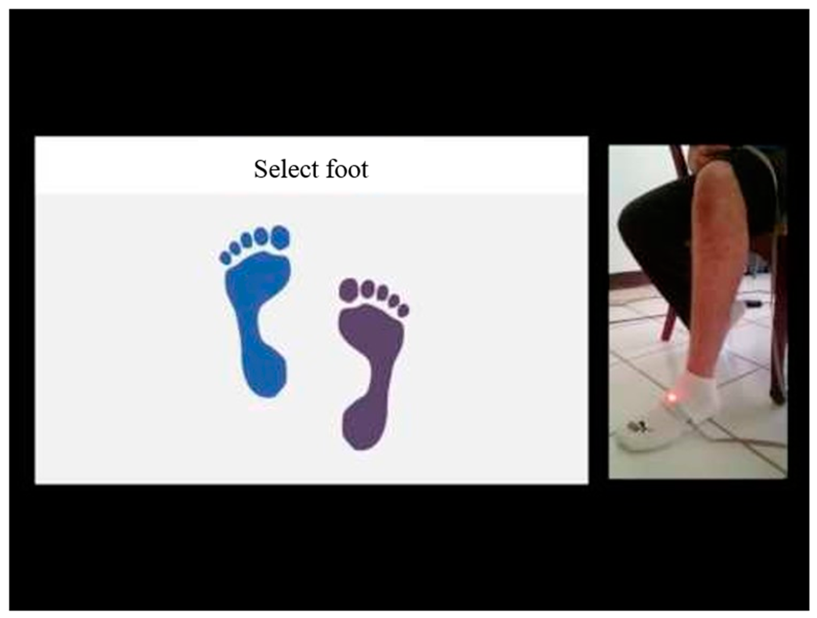
3.5. Communication between Arduino and Unity
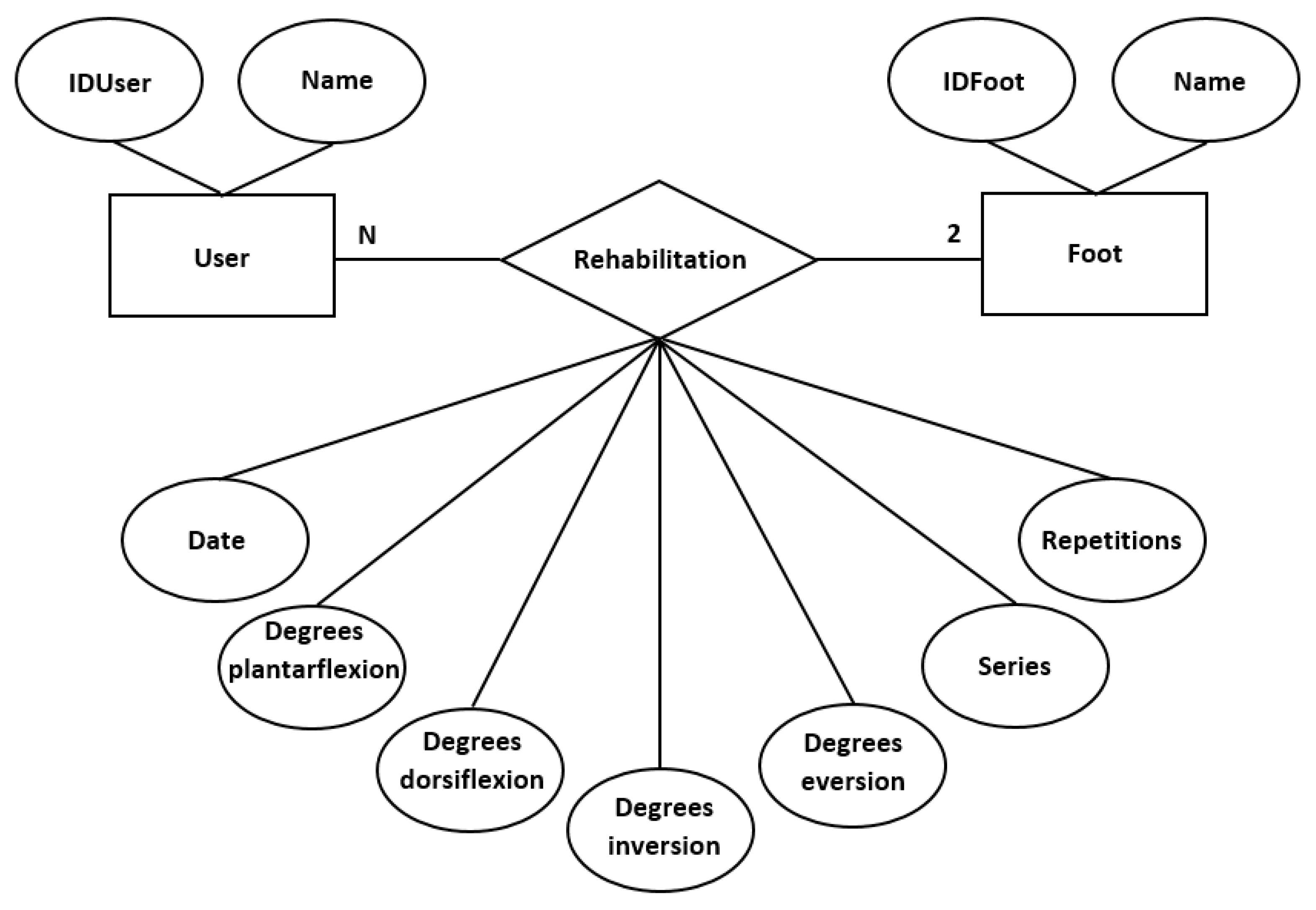
3.6. SQLite
4. Experimental Results and Discussion
4.1. Motion Range Evaluation
4.2. Therapist Evaluation
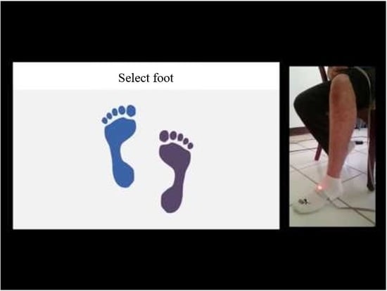
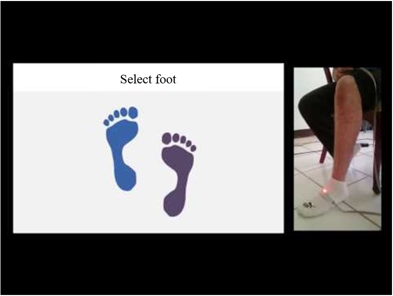
4.3. Evaluation with Application
4.4. Results
5. Conclusions
Supplementary Materials
Author Contributions
Funding
Acknowledgments
Conflicts of Interest
References
- Alcocer, W.; Vela, L.; Blanco, A.; Gonzalez, J.; Oliver, M. Major Trends in the Development of Ankle Rehabilitation Devices. Dyna 2012, 79, 45–55. [Google Scholar]
- English, B. Phases of Rehabilitation. Foot Ankle Clin. 2013, 18, 357–367. [Google Scholar] [CrossRef] [PubMed]
- Meng, W.; Xie, S.Q.; Liu, Q.; Lu, C.Z.; Ai, Q. Robust Iterative Feedback Tuning Control of a Compliant Rehabilitation Robot for Repetitive Ankle Training. IEEE/ASME Trans. Mechatron. 2017, 22, 173–184. [Google Scholar] [CrossRef]
- Rosado, W.M.; Valdés, L.G.; Ortega, A.B.; Ascencio, J.R.; Beltrán, C.D. Passive Rehabilitation Exercises with an Ankle Rehabilitation Prototype Based in a Robot Parallel Structure. IEEE Lat. Am. Trans. 2017, 15, 48–56. [Google Scholar] [CrossRef]
- Sandoval-Palomares, J.J.; Yáñez-Mendiola, J.; Gómez-Espinosa, A.; López-Vela, J.M. Portable System for Monitoring the Microclimate in the Footwear-Foot Interface. Sensors 2016, 16, 1059. [Google Scholar] [CrossRef] [PubMed]
- Nguyen, L.V.; La, H.M. Real-Time Human Foot Motion Localization Algorithm with Dynamic Speed. IEEE Trans. Hum.-Mach. Syst. 2016, 46, 822–833. [Google Scholar] [CrossRef]
- Wang, Z.; Zhao, H.; Qiu, S.; Gao, Q. Stance-Phase Detection for ZUPT-Aided Foot-Mounted Pedestrian Navigation System. IEEE/ASME Trans. Mechatron. 2015, 20, 3170–3181. [Google Scholar] [CrossRef]
- Prieto, J.; Mazuelas, S.; Win, M.Z. Context-Aided Inertial Navigation via Belief Condensation. IEEE Trans. Signal Process. 2016, 64, 3250–3261. [Google Scholar] [CrossRef]
- Ren, M.; Pan, K.; Liu, Y.; Guo, H.; Zhang, X.; Wang, P. A Novel Pedestrian Navigation Algorithm for a Foot-Mounted Inertial-Sensor-Based System. Sensors 2016, 16, 139. [Google Scholar] [CrossRef] [PubMed]
- Bao, S.-D.; Meng, X.-L.; Xiao, W.; Zhang, Z.-Q. Fusion of Inertial/Magnetic Sensor Measurements and Map Information for Pedestrian Tracking. Sensors 2017, 17, 340. [Google Scholar] [CrossRef] [PubMed]
- Shi, W.; Wang, Y.; Wu, Y. Dual MIMU Pedestrian Navigation by Inequality Constraint Kalman Filtering. Sensors 2017, 17, 427. [Google Scholar] [CrossRef] [PubMed]
- Pham, D.D.; Suh, Y.S. Pedestrian Navigation Using Foot-Mounted Inertial Sensor and LIDAR. Sensors 2016, 16, 120. [Google Scholar] [CrossRef] [PubMed]
- Ilyas, M.; Cho, K.; Baeg, S.-H.; Park, S. Drift Reduction in Pedestrian Navigation System by Exploiting Motion Constraints and Magnetic Field. Sensors 2016, 16, 1455. [Google Scholar] [CrossRef] [PubMed]
- Fusca, M.; Negrini, F.; Perego, P.; Magoni, L.; Molteni, F.; Andreoni, G. Validation of a Wearable IMU System for Gait Analysis: Protocol and Application to a New System. Appl. Sci. 2018, 8, 1167. [Google Scholar] [CrossRef]
- Suh, Y.S. Inertial Sensor-Based Smoother for Gait Analysis. Sensors 2014, 14, 24338–24357. [Google Scholar] [CrossRef] [PubMed]
- Tunca, C.; Pehlivan, N.; Ak, N.; Arnrich, B.; Salur, G.; Ersoy, C. Inertial Sensor-Based Robust Gait Analysis in Non-Hospital Settings for Neurological Disorders. Sensors 2017, 17, 825. [Google Scholar] [CrossRef] [PubMed]
- Taborri, J.; Palermo, E.; Rossi, S.; Cappa, P. Gait Partitioning Methods: A Systematic Review. Sensors 2016, 16, 66. [Google Scholar] [CrossRef] [PubMed]
- Chirakanphaisarn, N. Measurement and Analysis System of the Knee Joint Motion in Gait Evaluation for Rehabilitation Medicine. In Proceedings of the Fourth International Conference on Digital Information and Communication Technology and It’s Applications (DICTAP), Bangkok, Thailand, 6–8 May 2014. [Google Scholar] [CrossRef]
- Moufawad el Achkar, C.; Lenoble-Hoskovec, C.; Paraschiv-Ionescu, A.; Major, K.; Büla, C.; Aminian, K. Physical Behavior in Older Persons during Daily Life: Insights from Instrumented Shoes. Sensors 2016, 16, 1225. [Google Scholar] [CrossRef] [PubMed]
- Ladha, C.; O’Sullivan, J.; Belshaw, Z.; Asher, L. GaitKeeper: A System for Measuring Canine Gait. Sensors 2017, 17, 309. [Google Scholar] [CrossRef] [PubMed]
- Duong, P.D.; Suh, Y.S. Foot Pose Estimation Using an Inertial Sensor Unit and Two Distance Sensors. Sensors 2015, 15, 15888–15902. [Google Scholar] [CrossRef] [PubMed]
- Benoussaad, M.; Sijobert, B.; Mombaur, K.; Azevedo Coste, C. Robust Foot Clearance Estimation Based on the Integration of Foot-Mounted IMU Acceleration Data. Sensors 2016, 16, 12. [Google Scholar] [CrossRef] [PubMed]
- Zhou, Q.; Zhang, H.; Lari, Z.; Liu, Z.; El-Sheimy, N. Design and Implementation of Foot-Mounted Inertial Sensor Based Wearable Electronic Device for Game Play Application. Sensors 2016, 16, 1752. [Google Scholar] [CrossRef] [PubMed]
- Mitschke, C.; Heß, T.; Milani, T.L. Which Method Detects Foot Strike in Rearfoot and Forefoot Runners Accurately when Using an Inertial Measurement Unit? Appl. Sci. 2017, 7, 959. [Google Scholar] [CrossRef]
- Kok, M.; Hol, J.D.; Schön, T.B. An optimization-based approach to human body motion capture using inertial sensors. IFAC Proc. Vol. 2014, 47, 79–85. [Google Scholar] [CrossRef]
- Seel, T.; Ruppin, S. Eliminating the Effect of Magnetic Disturbances on the Inclination Estimates of Inertial Sensors. IFAC-Pap. 2017, 50, 8798–8803. [Google Scholar] [CrossRef]
- Seel, T.; Werner, C.; Schauer, T. The adaptive drop foot stimulator—Multivariable learning control of foot pitch and roll motion in paretic gait. Med Eng. Phys. 2016, 38, 1205–1213. [Google Scholar] [CrossRef] [PubMed]
- Giggins, O.M.; Sweeney, K.T.; Caulfield, B. Rehabilitation exercise assessment using inertial sensors: A cross-sectional analytical study. J. NeuroEng. Rehabil. 2014, 11, 158. [Google Scholar] [CrossRef]
- Shepherd, J.B.; Rowlands, D.D.; James, D.A. A Skill Acquisition Based Framework for Aiding Lower Limb Injury Rehabilitation using a Single Inertial Sensor with Concurrent Visual Feedback. Procedia Eng. 2016, 147, 632–636. [Google Scholar] [CrossRef]
- Long, Y.; Du, Z.-J.; Wang, W.-D.; Zhao, G.-Y.; Xu, G.-Q.; He, L.; Mao, X.-W.; Dong, W. PSO-SVM-Based Online Locomotion Mode Identification for Rehabilitation Robotic Exoskeletons. Sensors 2016, 16, 1408. [Google Scholar] [CrossRef] [PubMed]
- Zhang, H.; Hernandez, D.E.; Su, Z.; Su, B. A Low Cost Vision-Based Road-Following System for Mobile Robots. Appl. Sci. 2018, 8, 1635. [Google Scholar] [CrossRef]
- Borraz, R.; Navarro, P.J.; Fernández, C.; Alcover, P.M. Cloud Incubator Car: A Reliable Platform for Autonomous Driving. Appl. Sci. 2018, 8, 303. [Google Scholar] [CrossRef]
- Elangovan, K.; Krishnasamy Tamilselvam, Y.; Mohan, R.E.; Iwase, M.; Takuma, N.; Wood, K.L. Fault Diagnosis of a Reconfigurable Crawling–Rolling Robot Based on Support Vector Machines. Appl. Sci. 2017, 7, 1025. [Google Scholar] [CrossRef]
- Seel, T.; Raisch, J.; Schauer, T. IMU-Based Joint Angle Measurement for Gait Analysis. Sensors 2014, 14, 6891–6909. [Google Scholar] [CrossRef] [PubMed]
- Seel, T.; Graurock, D.; Schauer, T. Realtime Assessment of Foot Orientation by Accelerometers and Gyroscopes. Curr. Dir. Biomed. Eng. 2015, 1, 446–469. [Google Scholar] [CrossRef]
- “InvenSense Inc”. MPU-6000 and MPU-6050 Product Specification Rev. 3.4. Available online: https://store.invensense.com/datasheets/invensense/MPU-6050_DataSheet_V3%204.pdf (accessed on 14 July 2018).
- “I2Cdevlib”. MPU-6050 6-Axis Accelerometer/Gyroscope, I2Cdevlib Device Source and Documentation. Available online: http://www.i2cdevlib.com/devices/mpu6050 (accessed on 14 July 2018).
- Sabatini, A.M. Kalman-Filter-Based Orientation Determination Using Inertial/Magnetic Sensors: Observability Analysis and Performance Evaluation. Sensors 2011, 11, 9182–9206. [Google Scholar] [CrossRef] [PubMed]
- “MPU-6050 Accelerometer + Gyro”. Example Sketch (Base Code). Available online: https://playground.arduino.cc/Main/MPU-6050 (accessed on 14 July 2018).
- “42Bots”. Arduino Script for MPU-6050 Auto-Calibration. Available online: https://42bots.com/tutorials/arduino-script-for-mpu-6050-auto-calibration/ (accessed on 14 July 2018).


| Pin AD0 | Address 12C |
|---|---|
| AD0 = HIGH (5 V) | 0 × 69 |
| AD0 = LOW (GND or NC) | 0 × 68 |
| MPU-6050 | Teensy 2.0 |
|---|---|
| VCC | 3.3 V |
| GND | GND |
| SCL | D0 |
| SDA | D1 |
| Bluetooth HC-05 | Teensy 2.0 |
|---|---|
| VCC | 5 V |
| GND | GND |
| RXD | B1 |
| TXD | D2 |
© 2018 by the authors. Licensee MDPI, Basel, Switzerland. This article is an open access article distributed under the terms and conditions of the Creative Commons Attribution (CC BY) license (http://creativecommons.org/licenses/by/4.0/).
Share and Cite
Gómez-Espinosa, A.; Espinosa-Castillo, N.; Valdés-Aguirre, B. Foot-Mounted Inertial Measurement Units-Based Device for Ankle Rehabilitation. Appl. Sci. 2018, 8, 2032. https://doi.org/10.3390/app8112032
Gómez-Espinosa A, Espinosa-Castillo N, Valdés-Aguirre B. Foot-Mounted Inertial Measurement Units-Based Device for Ankle Rehabilitation. Applied Sciences. 2018; 8(11):2032. https://doi.org/10.3390/app8112032
Chicago/Turabian StyleGómez-Espinosa, Alfonso, Nancy Espinosa-Castillo, and Benjamín Valdés-Aguirre. 2018. "Foot-Mounted Inertial Measurement Units-Based Device for Ankle Rehabilitation" Applied Sciences 8, no. 11: 2032. https://doi.org/10.3390/app8112032
APA StyleGómez-Espinosa, A., Espinosa-Castillo, N., & Valdés-Aguirre, B. (2018). Foot-Mounted Inertial Measurement Units-Based Device for Ankle Rehabilitation. Applied Sciences, 8(11), 2032. https://doi.org/10.3390/app8112032