Article

Numerical Investigation of the Nonlinear Composite Action of FRP-Concrete Hybrid Beams/Decks

1
School of Urban Construction, Wuhan University of Science and Technology, Wuhan 430065, China
2
Department of Civil, Architectural & Environmental Engineering, Missouri University of Science and Technology, Rolla, MO 65409, USA
3
Department of Civil and Environmental Engineering, The Hong Kong Polytechnic University, Hong Kong, China
4
Department of Civil, Construction and Environmental Engineering, Iowa State University, Town Engr. Building, Ames, IA 50011, USA
*
Author to whom correspondence should be addressed.
Appl. Sci. 2018, 8(11), 2031; https://doi.org/10.3390/app8112031
Submission received: 1 October 2018 / Revised: 15 October 2018 / Accepted: 20 October 2018 / Published: 23 October 2018
(This article belongs to the Special Issue Emerging Construction Materials and Sustainable Infrastructure)

Abstract

:

Featured Application

This paper proposed a finite difference method that can model the interfacial slip of FRP-concrete hybrid beam (FCHB). This method was used to evaluate the interfacial slip and deflection of FCHB using different shear connections.

Abstract

Interfacial slip can cause rigidity degradation and stress concentration in fiber-reinforced polymer-concrete hybrid beam (FCHB). Therefore, precisely evaluating the composite action between fiber-reinforced polymer (FRP) and concrete of FCHB plays a pivotal role in structural analysis and design. Previous push-out tests showed that most connections for FCHB behave nonlinearly in load-slip relationships even at a low load level. However, existing analytical equations have their limitations due to the assumption of linear load-slip interfacial relationship which is not suitable for FCHB. The originality of this paper is to propose a finite difference method (FDM) to elaborate the interfacial slip and shear stress. FDM agreed well with the analytical solutions of the linear load-slip relationships for connections. Results indicate that higher accurateness can be obtained by using more elements. And 40 elements for half span of FCHB can reduce the error of numerical results to 1%. Then, the proposed FDM was expanded to predict the interfacial behavior of FCHB considering nonlinear interfacial load-slip relationships. It was found that perforated FRP rib connections can ensure nearly full composite action and the bolted connection can lead to a very high slip level. The use of ultra-high performance concrete (UHPC) results in a higher degree of composite action than normal concrete. The deflection considering slip was computed by adding deformation under full composition action and that caused by the slip effect. It was suggested that high strength steel bolts are effective both in normal concrete and UHPC. When the slip modulus is suggested to be larger than 20 kN/mm, the capacity per bolt should be larger than 20 kN.

1. Introduction

High strength-to-weight ratio and durability under corrosive chemical conditions have made fiber-reinforced polymer (FRP) composite materials an attractive solution to bridge members [1,2,3]. In the last two decades, there has been an increasing interest in using FRP composites to repair and strengthen reinforced concrete (RC) and steel structures [4,5]. In the new construction of bridge superstructures, hybrid FRP-concrete beams and decks provide benefits by combining the stiffness and low cost of concrete with the light-weight, fabrication speed, high strength, and durability of FRP [6]. Among them, pultruded FRP-concrete hybrid beams/decks have been proposed as an advanced [7,8,9] solution for bridge superstructures. After taking into account the expected improvements in transport, installation, and life-cycle differences, the initial cost of FRP can be offset, thereby leading the system competitive in the standard short-span bridge market and bridge decks [10,11,12]. The primary difference between these FRP-concrete hybrid beams/decks and the currently widely used traditional steel-concrete composite beams is that the FRP cannot be welded easily like steel, so the interfacial connections are usually weaker in terms of capacity and slip modulus [13,14,15,16,17,18]. The static [19,20,21], fatigue [22], aggressive exposure [22], dynamic [23], and long-term [24] performances have been investigated in previous research. Hence the interfacial slip between FRP and concrete is expected to be high and reduces the stiffness and capacity and fiber-reinforced polymer-concrete hybrid beam (FCHB) [19,20,25,26]. Strong interfacial connections are recommended to be used in the real applications of FCHB bridges [27,28,29,30]. However, theoretically speaking, there should be a slip between FRP concrete even when strong connectors (e.g., perforated FRP ribs [10,13] and FRP shear keys [14,18]) are used. The evaluation of interfacial slip is an inevitable topic in the research and design of FCHB. Many researchers have proposed analytical solutions to quantifying the interfacial slip of FCHB according to a linear load-slip relationship of shear connection [31,32]. A slip modulus was employed based on a chord slope of FRP-concrete push-out testing [10,14,16]. However, this simplification is not true for nearly all the connectors because nonlinearity occurs even at low load level which makes the chord slope different from the tangential slope [10,14,15,16,31,32,33]. Therefore, a method that can consider the nonlinear interfacial load-slip relationship is needed.
This study reports a simple but fairly accurate solution for the nonlinear slip process using the finite difference method (FDM) in association with linear and nonlinear bond-slip models. Based on the computation results, existing analytical solutions using linear interfacial load-slip relationships were calibrated, and different bond-slip models are discussed.

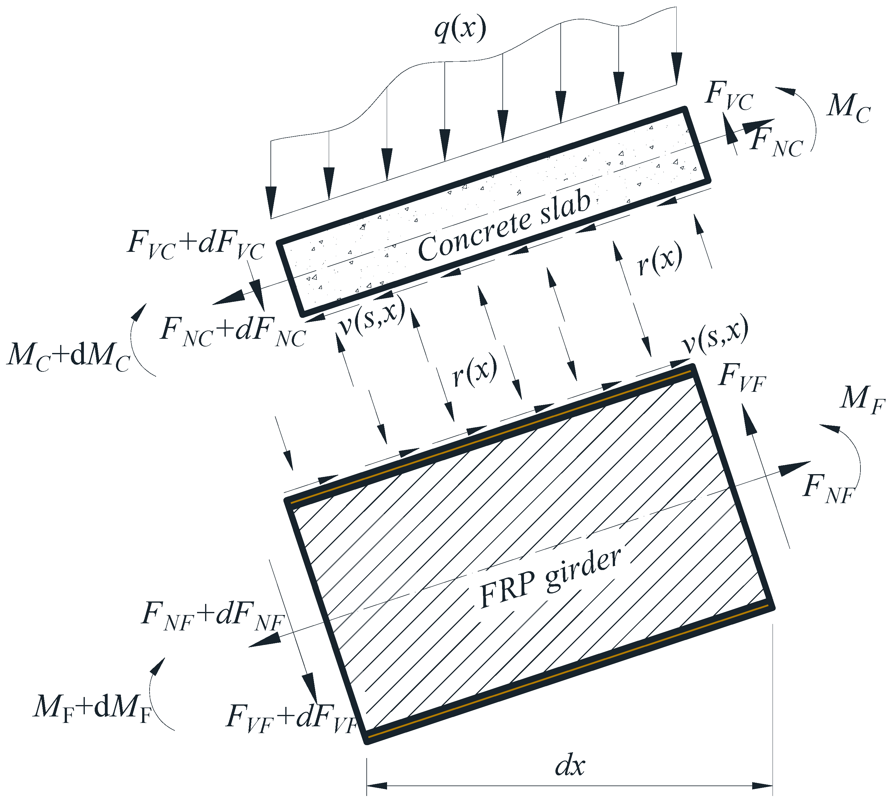
2. Construction of Governing Equation

Assuming that (a) only shear connectors provide composite action between the FRP and concrete components; (b) the concrete slab and FRP profile can be simplified as two components discontinuously joined (see Figure 1), the longitudinal shear flow across the interface is transferred at a discrete number of points by the action of the shear connectors; and (c) there is no separation along the normal direction of the interface, the interfacial shear force flow can be obtained as
v ( x ) = n Q ( s ) / p
where v ( x ) is the distributed interfacial shear force, n is the connector number of the connector in the lateral direction, Q ( s ) is load-slip relationship per connector, and p is the longitudinal space between connectors.
For a simply supported beam, equilibrium of the finite length dx (Figure 1) in the horizontal direction gives
d F N C ( x ) d x = d F N F ( x ) d x = v ( x )
where F N C ( x ) and F N F ( x ) are the axial force in concrete and FRP, respectively.
Equilibriums in the vertical direction of the shear force and moment give
V c ( x ) + V F ( x ) = V ( x )
d M c ( x ) d x v ( x ) h c 2 + r ( x ) d x 2 + V c ( x ) = 0
d M F ( x ) d x v ( x ) h F 2 r ( x ) d x 2 + V F ( x ) = 0
where V c ( x ) and V F ( x ) are the shear force carried by concrete and FRP, respectively, V ( x ) is the sectional shear force. M c ( x ) and M F ( x ) are flexural moment carried by concrete and FRP, respectively; h c is the distance from the bottom of concrete to its neutral axis; h F is the distance from the top of FRP to its neutral axis, and r ( x ) is distributed normal force along FRP-concrete interface.
Considering assumption (v), the curvature compatibility between the concrete and FRP gives
ϕ ( x ) = M c ( x ) E c I c = M F ( x ) E F x I F x
where E F x is the elastic modulus of FRP; I F x is moment inertia of FRP; E c is the elastic modulus of concrete; I c is moment inertia of concrete, and ϕ is the curvature of the beam.
FRP-concrete hybrid beams/decks are modeled elastically since FRP materials are inherent linear elastic and the concrete stays at a low stress level before the failure of FRP webs. The orthotropic mechanical properties of the FRP composite material are the same in the web and flanges, however, in this study, the longitudinal modulus of FRP is employed to compute the sectional rigidity. Therefore, strains of concrete ε c ( x , y ) and FRP ε c ( x , y ) are calculated from the moment and axial force as
ε c ( x , y ) = M c ( x ) ( h c / 2 y ) E c I c F N C ( x ) E c A c , 0 y h c
ε F ( x , y ) = M F ( x ) ( h F / 2 + y ) E F x I F x + F N F ( x ) E F x A F , h F y 0
where y is the vertical coordinate that has an original point at FRP-concrete interface and has a direction upward. Equations (7) and (8) give the strains at the interface respectively as
ε c b ( x ) = ε c ( x , 0 ) = M c ( x ) h c 2 E c I c F N C ( x ) E c A c
ε F t ( x ) = ε F ( x , 0 ) = M F ( x ) h F 2 E F x I F x + F N F ( x ) E F x A F
where A C and A F are the area of concrete and FRP, respectively.
The relative strain difference caused by the slip at the interface ε s l i p ( x ) is calculated as
ε s l i p ( x ) = ε c b ( x ) ε F t ( x )
Also, the relative slip strain at the interface is calculated by differentiating the slip
s ( x ) = ε s l i p ( x )
Substituting Equations (7)–(11) to (12), the difference of the slip would be
s ( x ) = ϕ ( x ) h 0 F N C ( x ) E c A c F N F ( x ) E F x A F
Solving Equations (6) and (13) yields
ϕ ( x ) = V ( x ) n h 0 Q ( x ) / p E F x I 0
Derivation with respect to x in Equation (13) and then using Equation (14) gives the differential equation as:
s ( x ) A 1 E F x I 0 n p Q ( s ) = A 1 2 h 0 E F x I 0 V ( x )
where A 1 = I 0 / A 0 + h 0 2 , A 0 = A F A C / ( α E A F + A C ) , I 0 = I C / α E + I F , and α E = E F x / E C .
The boundary conditions are given by symmetricity at mid-span as
s ( L / 2 ) = 0
And at the supports
d s d x ( 0 ) = d s d x ( L ) = 0
Since Q(s) is usually a nonlinear function, so the analytical solution is needed to solve Equation (15).

3. Numerical Solution of the Governing Equation Using FDM

For similarity, Equation (15) is rewritten as
s ( x ) m Q ( s ) = η V ( x )
where m = A 1 E F x I 0 n p , and η = A 1 2 h 0 E F x I 0 . And for one-point loading, V ( x ) = P / 2 .
The central difference approximations for Equation (18) lead to
d 2 s ( x i ) d x 2 = s i + 1 2 s i + s i 1 h 2
where h is the discretization step, which is given by h = L / N , L is the bond length of the composite-substrate interface and N is the number of discretization. The step h between consecutive points x i , i = 0, 1, 2, …, N, was selected with N as the largest integer above which no gain in accuracy could be detected.
Substituting Equation (19) into Equation (18) yields to
s i + 1 2 s i + s i 1 h 2 m Q ( s i ) = η P 2
Rearranging Equation (12) gives
s i + 1 2 s i + s i 1 h 2 m Q ( s i ) = η P 2 h 2
Boundary conditions Equations (16) and (17) give
s 1 s 1 = 0
However, s 1 is not in the domain thereby creating a difficulty. The solution is to extend the original domain from [ 0 , N h ] to [ 1 , N h ] . Therefore, the nonlinear system in Equation (13) becomes
{ s 1 s 1 = 0 s i + 1 2 s i + s i 1 h 2 m Q ( s i ) + η P h 2 / 2 = 0 ,   i = 0 , 1 , 2 , , N s N = 0
Since Q ( s i ) results in nonlinearity of Equation (23), the system of equations cannot be solved using Gaussian elimination or any special linear system. Hence, Equation (23) was solved by the system of equations with the Newton-Raphson iteration technique as follows:
{ s i } j + 1 = { s i } j J 1 ( s i ) * f i ( s i )
where { s i } j and { s i } j + 1 are the slip at the j-th and j+1-th iteration, respectively, J 1 ( s ) is the inverse of the Jacobian matrix for this system, and fi(si) is the first member of Equation (23) at point i.
The convergence of the system was defined according to:
| { s i } j + 1 { s i } j | 0

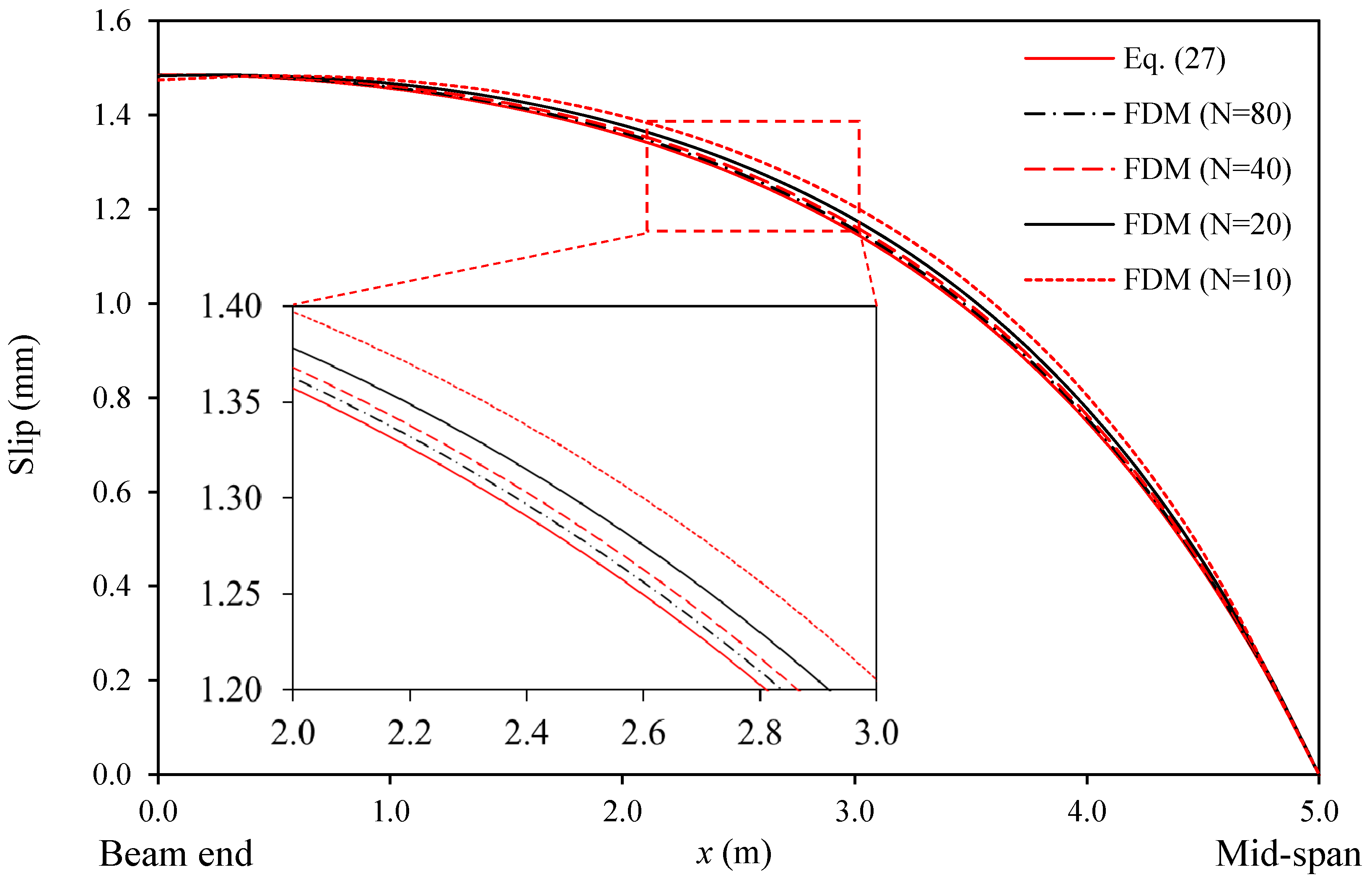
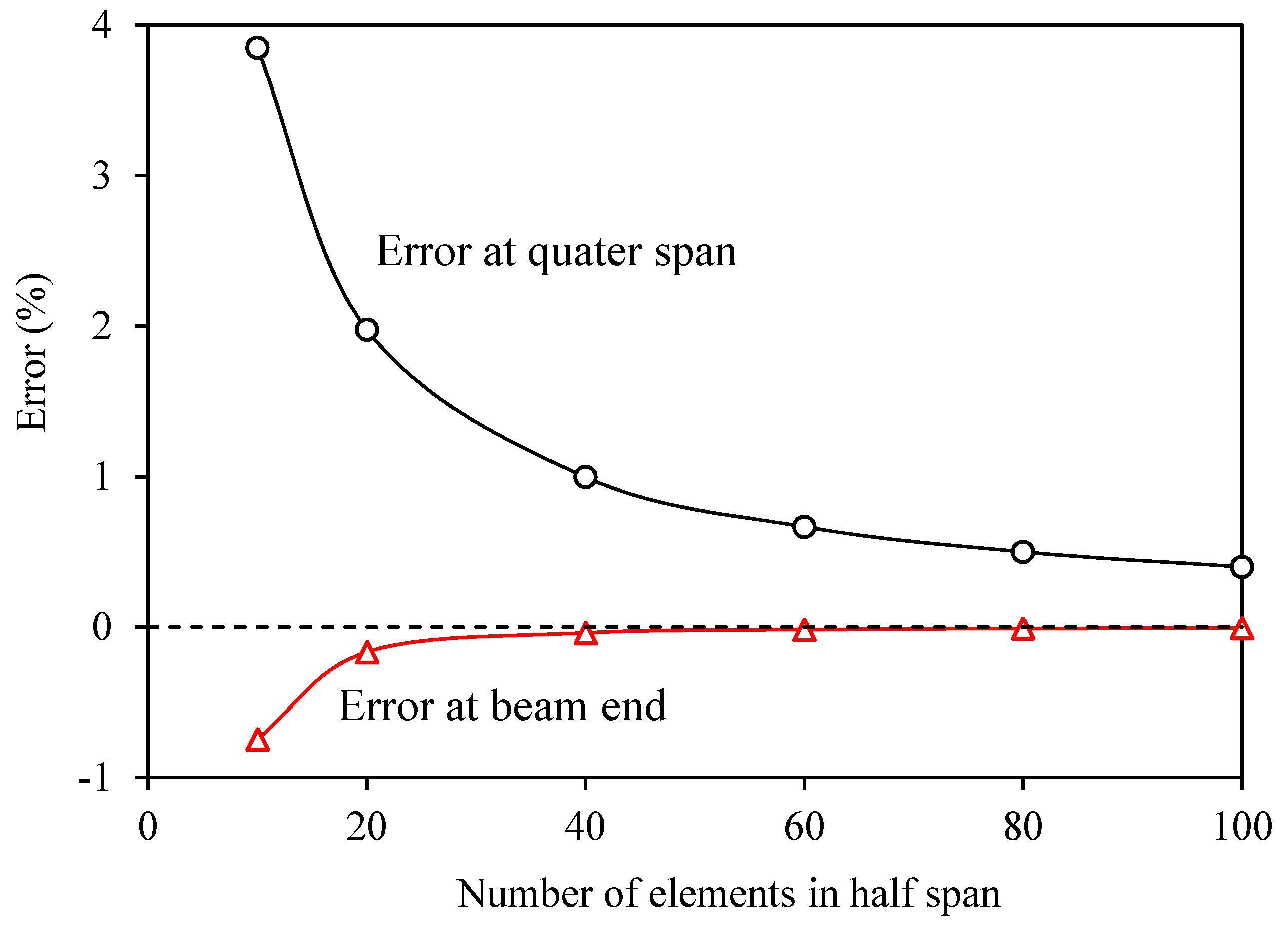
4. Validation of Numerical Models Against Analytical Solution

In this section, the results of FDM will be compared with the existing results given in the literature. In previous research, when only the linear part of the load-slip curve is considered in analysis procedures, the theory can be based on a constant slip modulus, K. Therefore, Q(s) = Ks can be used for Equation (15), by doing so one has
s ( x ) α 2 s ( x ) = α 2 β V ( x )
where α 2 = k A 1 / ( E F x I 0 ) , β = A 1 h 0 / k .
Solving Equation (26) gives
s ( x ) = β P 2 [ 1 cos h ( α x ) / cos h ( α L 2 ) ] , 0 < x < L / 2
Given the initial design of a FCHB as inputs: concrete width by height b c h c = 400 mm × 250 mm, FRP height h F = 750 mm, FRP width b F = 200 mm, FRP flange thickness t F l g = 10 mm, FRP web thickness t w e b = 20 mm, longitudinal space of steel bolts p = 400 mm, slip modulus of connectors K = 6 kN/mm, length of FCHB, L =10 m, longitudinal modulus of FCHB, E F x = 12.5   GPa , Young’s modulus of concrete E c = 30   GPa , and load at the mid-span P = 500 kN.
Figure 2 shows the results of slip distribution along the longitudinal direction given by FDM and analytical solutions given by Equation (27), respectively. Good agreement can be obtained by FDM. Figure 3 and Table 1 show the relationship between the error of FDM and the numbers of elements in half span. It can be clearly seen that the error decreases with the increasing of the element number. When the element number is 40, the error at quarter beam is less than 1%.

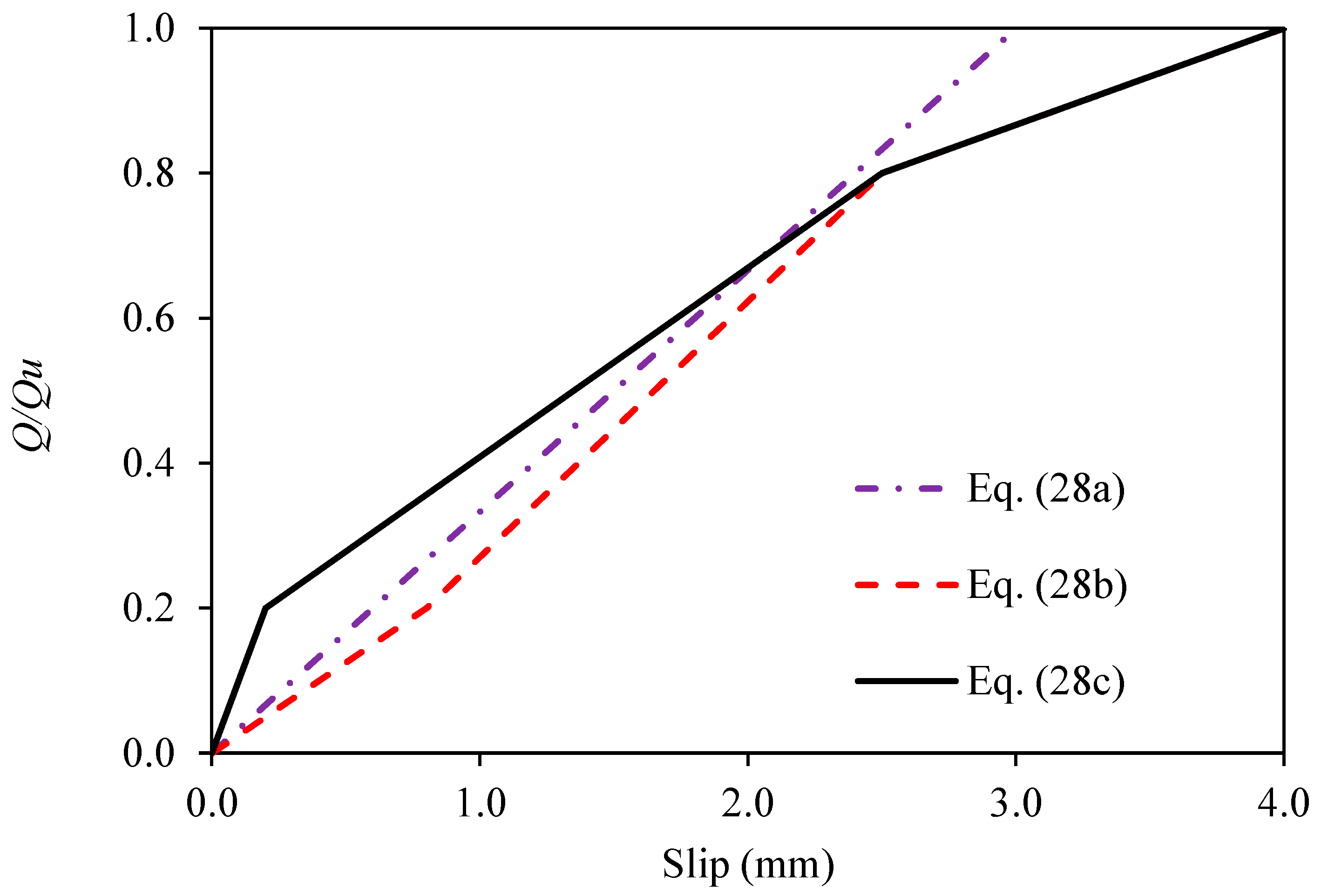
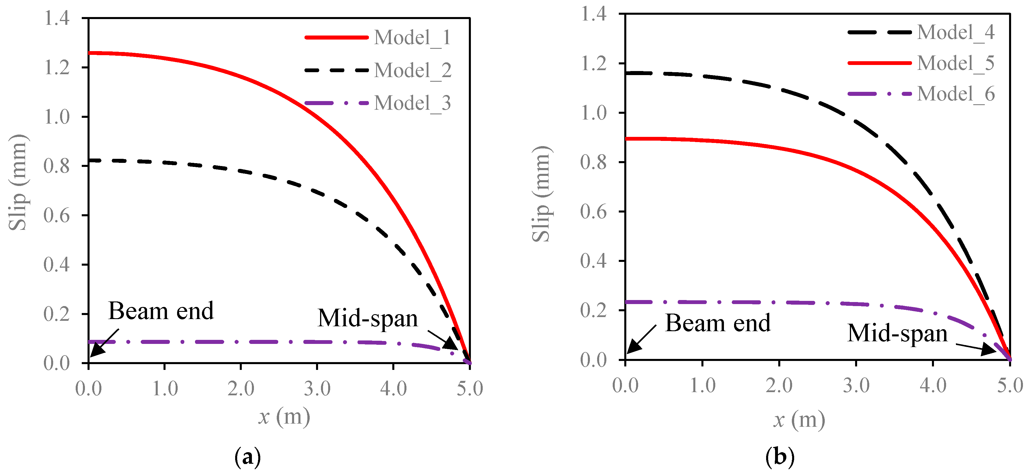
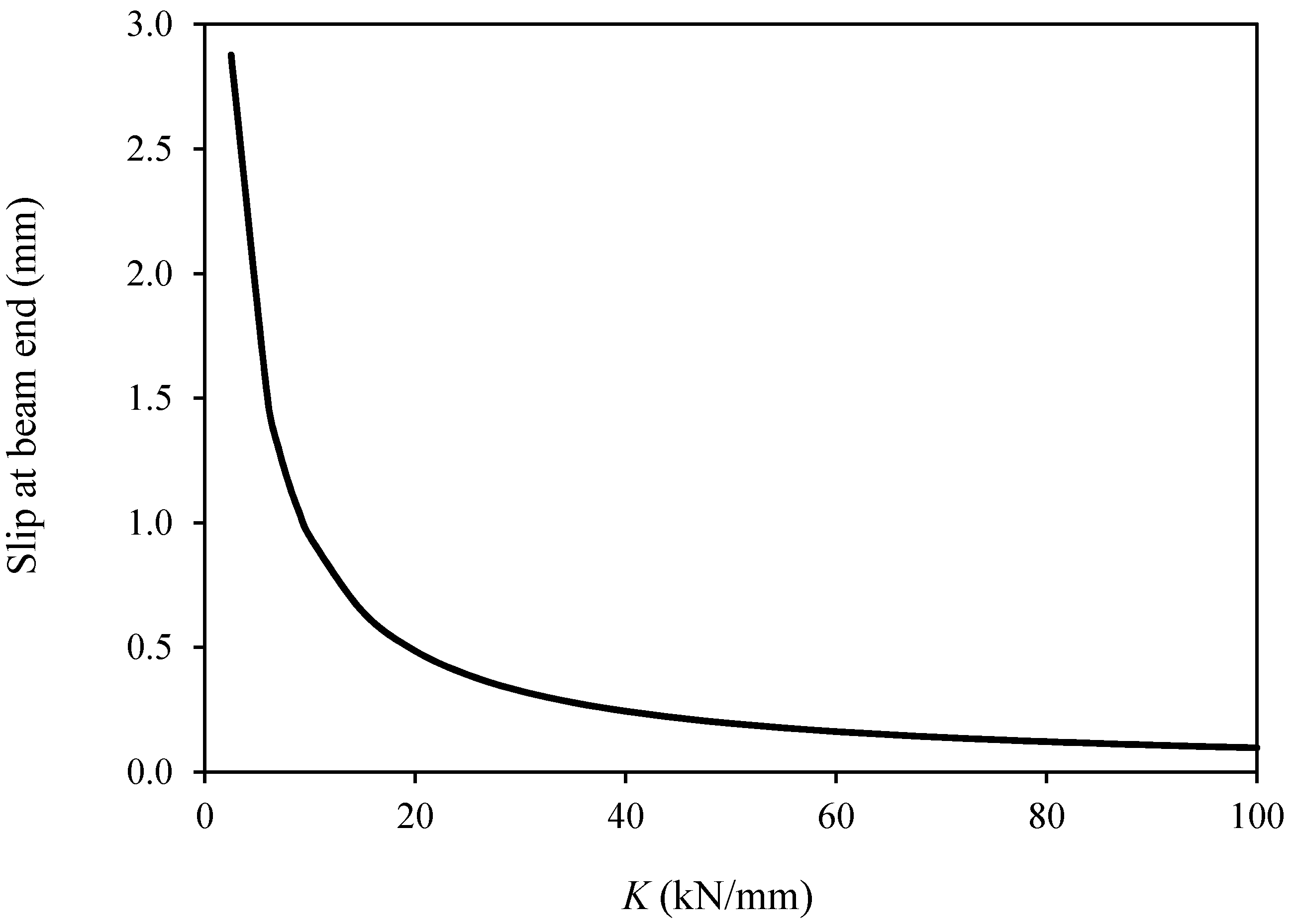
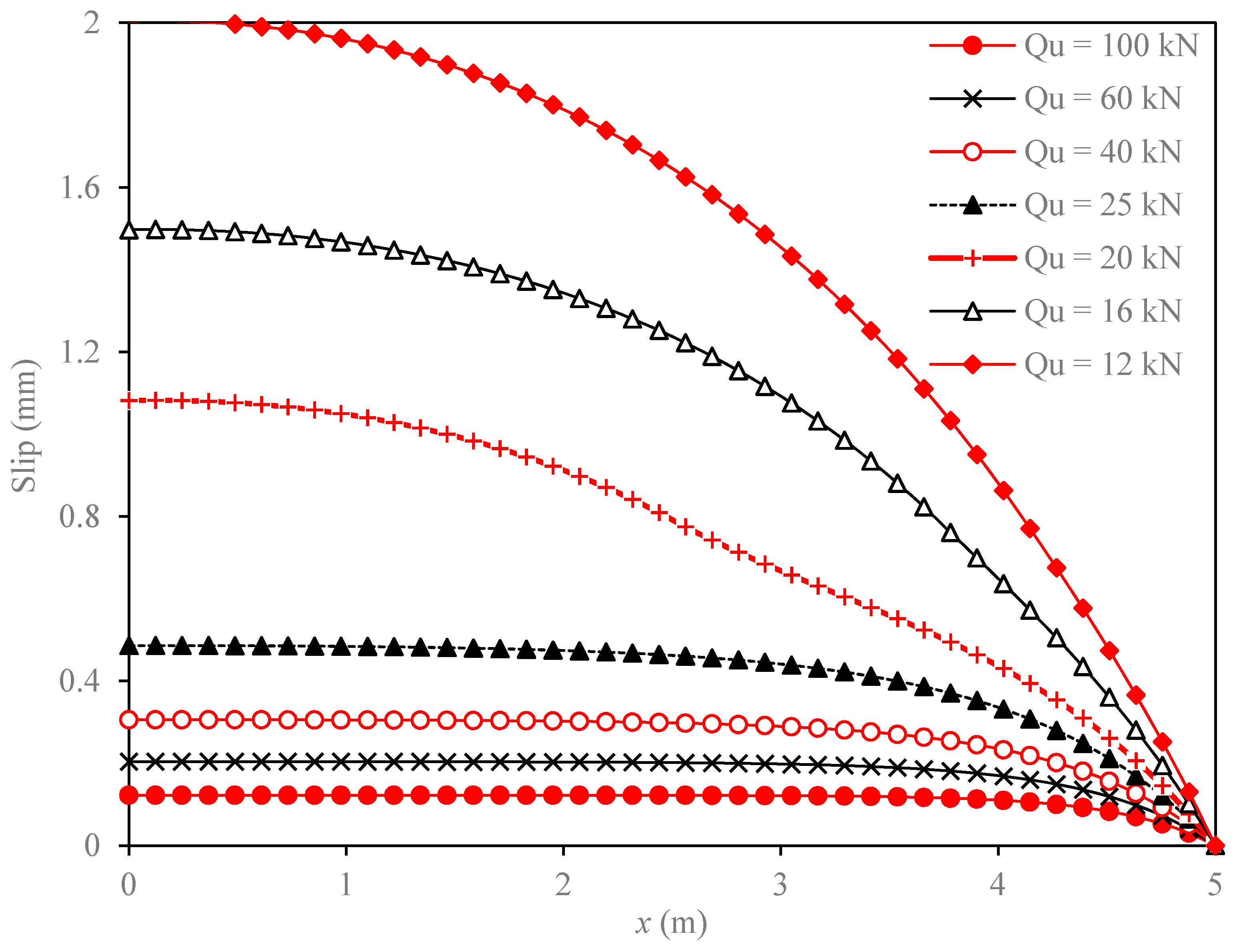
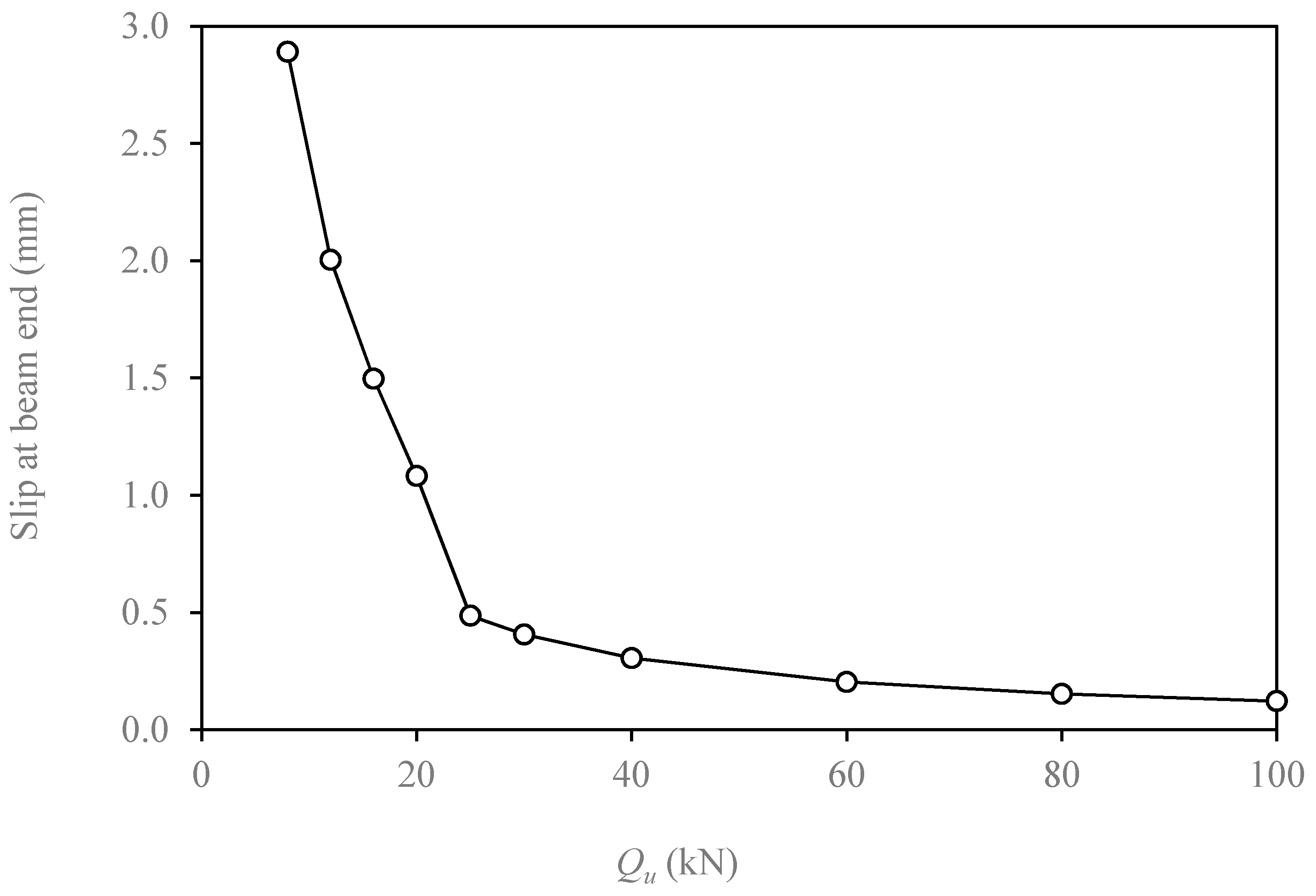
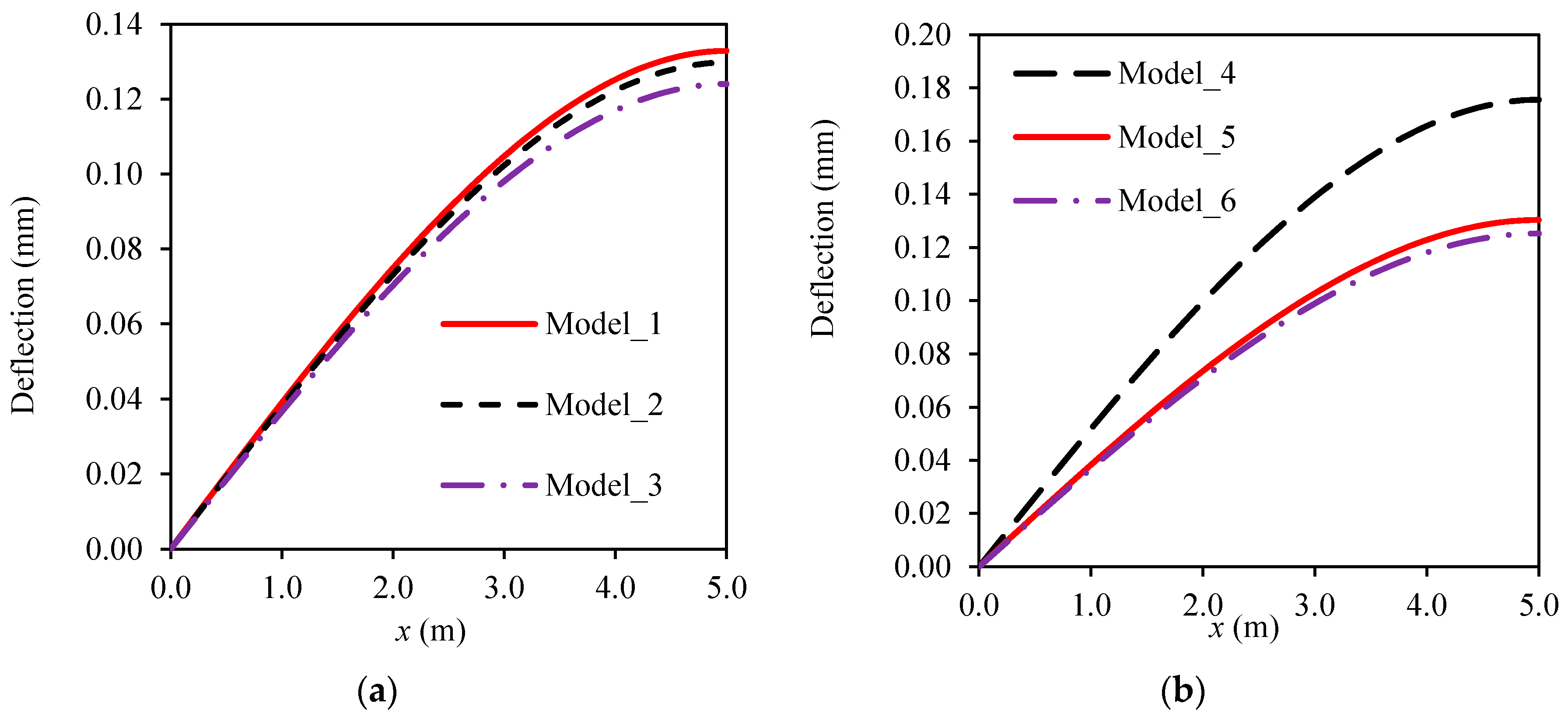
5. Load-slip Models for Connection of FRP-concrete Hybrid Beams/Decks

In this section, the choice of Q ( s ) models were made based on some formulas found in literatures [13,14,15]. The formulas have been given by the authors of this paper in previous literatures, which are presented in Table 2 and Figure 4.
Model_1~3 are based on linear load-slip relationship and different values of K given by Table 2 in Reference [13]. Model_1 and Model_2 reflect the average slip modulus of normal and high strength steel bolts, respectively. Model_3 uses the value of K for perforated FRP ribs.
Model_4~6 are based on nonlinear load-slip relationship given by Figure 11 in Reference [15] and can be seen in Figure 4 below. Model_5 is for the interface between FRP and normal concrete, and it consists of three parts: the compacting stage (0~0.2 Q u ); the hardening stage (0.2 Q u ~0.8 Q u ), and the softening stage (0.8 Q u ~ Q u ). The compacting stage is caused by packing the initial clearance between the bolt and the predrilled hole as well as the torsion of the bolts. In the hardening stage, the shear resistance is provided by the elastic flexure and shear deformation of the bolt. Finally, in the softening stage, the large deformation of the bolts and the local FRP around the hole provide the shear resistance.
Model_6 is for the high strength bolted connection between FRP and ultra-high performance concrete (UHPC) also consists of three parts, but they appear in a different pattern: the hardening stage (0~0.2 Q u ) is first, followed by the compacting stage (0.2 Q u ~0.8 Q u ), and finally the softening stage (0.8 Q u ~ Q u ).
Herein, according to the experimental data in Table 5 in Reference [15] and is also shown in Table 2 of this paper. The average load per bolts of ordinary strength bolts in the normal concrete is 28.5 kN. And the average loads of the high strength bolts in the normal strength concrete and the high strength bolts in UHPC are 40.8 kN and 52.3 kN, respectively.
Figure 5a shows that the Model_3 has a very small slip level (less than 0.1 mm at the load of 500 kN), which shows that almost full composite action has been obtained, which indicates that this type of connection is suitable for FCHB system. Also, Model_1 leads to almost 50% larger slip than Model_2 which means that the interfacial slip is very sensitive to the value of slip modulus of bolts. Figure 5b shows that the Model_6 ends at slip level less than 0.25 mm at the load of 500 kN, which shows that almost full composite action has been obtained by high-strength steel bolts in UHPC. So, which shows that the use of UHPC can impede the slip and ensure a high degree of composite action of FCHB system, which is experimentally validated by the flexural testing of an FRP truss-UHPC hybrid bridge system [34]. Also, Model_1 leads to almost 50% larger slip than Model_2 which means that the interfacial slip is very sensitive to the value of slip modulus of bolts.
Figure 6 shows that the relationship between slip at the beam end and the value of slip modulus of connectors. It can be seen that slip decreases dramatically with the increases of 2.5 kN/mm to about 25 kN/mm, and when K increases from 25 kN/mm to 100 kN/mm, the slip drops very slightly. This can be used to guide the design of FCHB system.
Figure 7 shows that the slip along the half span for different values of Q u in Model_6. It can be seen that for low composite action ( Q u 20 kN) design, the slip level is high because the slip close to the beam end enters the compacting stage (0.8 mm~2.5 mm). When the value of Q u changes from 20 kN to 25 kN, the slip increases dramatically (see Figure 8).

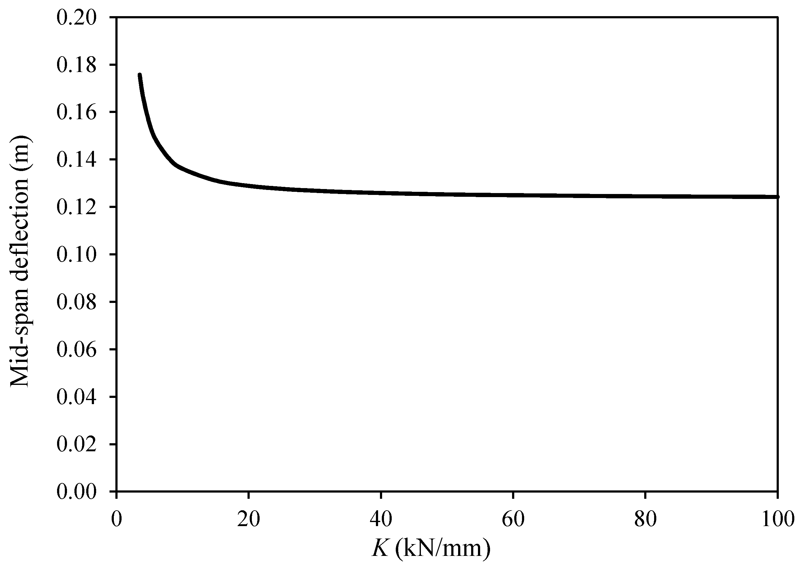
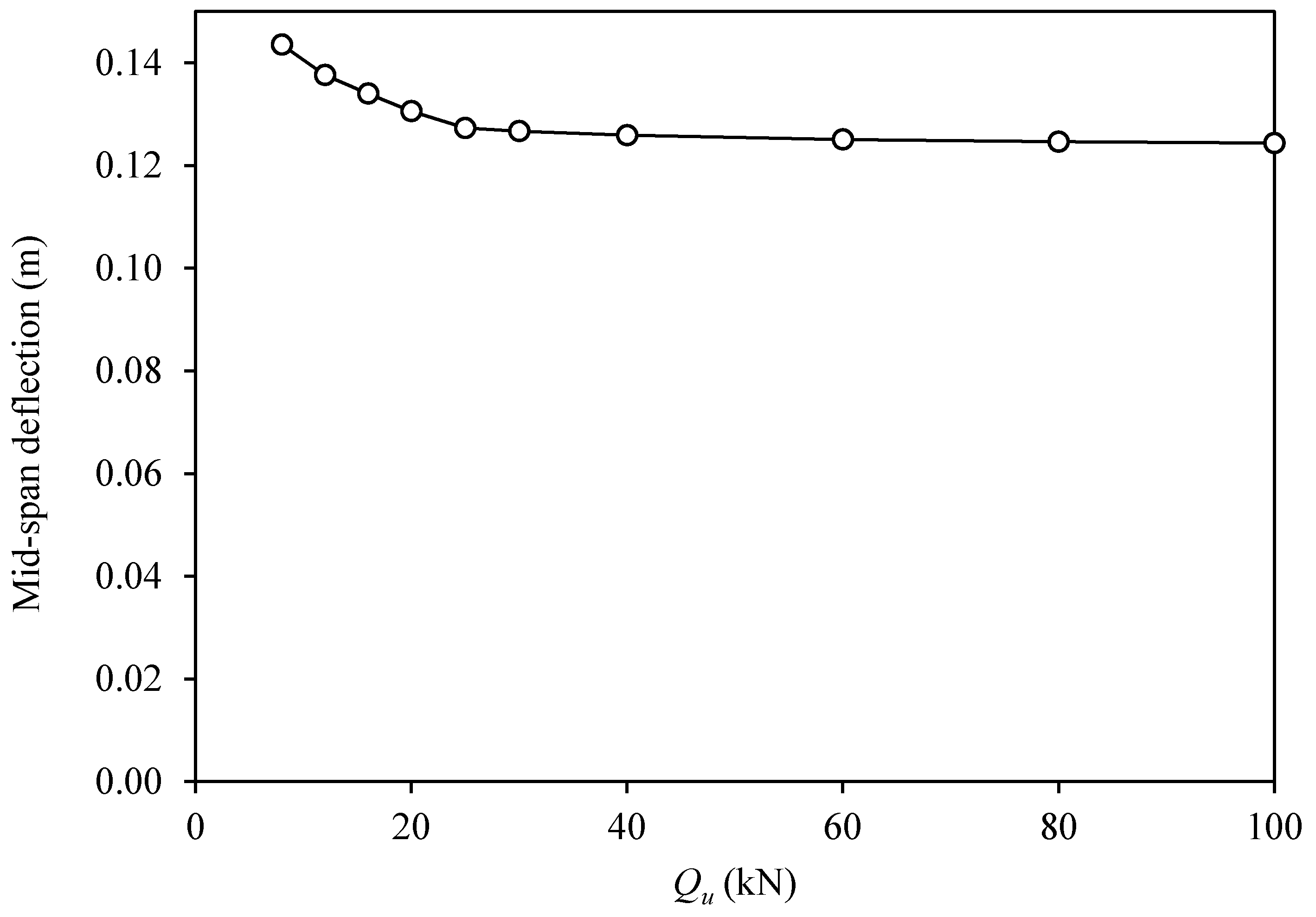
6. Evaluation of Deflection Considering Slip Effect

The total deflection can be computed by adding the additional deflection caused by slip to the deflection without slip [35].
δ ( x ) = δ f u l l ( x ) + δ s l i p ( x )
where δ ( x ) is the total deflection, δ f u l l ( x ) is the deflection assuming that full composite action is ensured between FRP and concrete, and δ s l i p ( x ) is the deflection caused by the slip effect.
The additional curvature due to the slip is a calculation from Equations (11) and (12) as
Δ ϕ ( x ) = ε s l i p ( x ) h 0 = s ( x ) h 0
Therefore, the deflection of the FCHB caused by slip effect can be computed as second order integration of Equation (30).
δ s l i p ( x ) = 0 x Δ ϕ ( x ) d x
The mid-span deflection, δ s l i p ( L / 2 ) of the FCHB caused by slip effect for three-point bending scenario has been analytically given in [35,36] as
δ s l i p ( L 2 ) = β P 2 h 0 [ L 2 + 1 α ( 1 e α L 1 + e α L ) ]
Herein, δ s l i p ( L / 2 ) is computed numerically using Equation (31) and analytically by Equation (32). The results are given in Table 3. It is found that with the increase of element numbers, the difference between the analytical and numerical result of δ s l i p ( L / 2 ) decreases. It should be noted that even using 10 elements in half span can lower the error of FDM to 0.225%.
Figure 9 shows that the deflection distribution of FCHB using Model_1, Model_2, and Model_3. The deflections at the mid-span of Model_1, Model_2, and Model_3 are 0.133 mm, 0.130 mm and 0.124 mm, respectively. It is interesting to see that using these three connections leads to a difference of less than 7.1%, which means that all of these connections behave similarly in terms of deflection. The deflections at the mid-span of Model_4, Model_5, and Model_6 are 0.176 mm, 0.130 mm, and 0.125 mm, respectively. The difference between Model_5 and Model_6 is 4.04%, which means using high strength bolts is effective both for normal concrete and UHPC. Therefore, it is suggested that high strength bolts are beneficial for limiting deflection caused by slip and the UHPC is not that a significant factor.
Figure 10 shows the relationship between mid-span deflection considering slip effect and the value of slip modulus of connectors (K). It can be found that in with the increase of K from very low to 20 kN/mm, mid-span deflection decreases sharply to a relatively stable value. And when K decreases from 40 kN/mm to 100 kN/mm, the drop is gradual. Thus K > 40 kN/mm is suggested to be used in FCHB.
A similar conclusion can be drawn in Figure 11. It can be found that in with the increase of Qu from very low to 25 kN, mid-span deflection decreases sharply to a relatively stable value. Qu ≥ 25 kN is suggested to be used in FCHB.

7. Conclusions

The interfacial load-slip model is an important material parameter for FRP-concrete hybrid beam systems. This paper presents a finite difference method based procedure to solve the problem. The following main conclusions can be drawn:
(i)
The finite difference method provides a numerical solution for the interfacial slip that can well agree with the analytical solution of linear load-slip relationship for connections.
(ii)
Higher accurateness can be obtained by using more elements. It is found that 40 elements for a half span of FCHB can lead to a small error (less than 1%).
(iii)
The FDM can be used for nonlinear load-slip relationship of connection.
(iv)
Perforated FRP rib connection, which normally has slip modulus larger than 100 kN/mm, provides nearly the full composite action.
(v)
The bolted connection in normal concrete leads to very high slip level, and when using UHPC as the concrete slab, the slip can be substantially reduced. And
(vi)
The FDM is effective and easy to be implemented using computer programs. Based on the findings in this paper, this method is recommended to predict the linear and nonlinear interfacial behavior of FRP-concrete hybrid beam.
(vii)
It was suggested that high strength steel bolts are effective both in normal concrete and UHPC. Moreover, when the slip modulus is suggested to be larger than 20 kN/mm and the capacity per bolt should be larger than 20 kN.

Author Contributions

J.G. contributes to the idea and funding support to this paper, X.Z. contributes to the methodology and the organization of this paper. H.S., C.J. and Z.L. contribute to the writing and revision of this paper.

Funding

This work is financially supported by the National Natural Science Foundation of China (Grant No. 51778508).

Acknowledgments

The corresponding author was formerly a student in School of Urban Construction, Wuhan Univ. of Science and Technology.

Conflicts of Interest

The authors declare no conflict of interest.

References

  1. Bakis, C.E.; Bank, L.C.; Brown, V.; Cosenza, E.; Davalos, J.F.; Lesko, J.J.; Machida, A.; Rizkalla, S.H.; Triantafillou, T.C. Fiber-reinforced polymer composites for construction—State-of-the-art review. J. Compos. Constr. 2002, 6, 73–87. [Google Scholar] [CrossRef]
  2. Jiang, C.; Wu, Y.F.; Wu, G. Plastic hinge length of FRP-confined square RC columns. J. Compos. Constr. 2014, 18, 04014003. [Google Scholar] [CrossRef]
  3. Wu, Y.F.; Jiang, C. Quantification of bond-slip relationship for externally bonded FRP-to-concrete joints. J. Compos. Constr. 2013, 17, 673–686. [Google Scholar] [CrossRef]
  4. Wang, H.T.; Wu, G.; Pang, Y.Y. Theoretical and Numerical Study on Stress Intensity Factors for FRP-Strengthened Steel Plates with Double-Edged Cracks. Sensors 2018, 18, 2356. [Google Scholar] [CrossRef] [PubMed]
  5. Zhu, C.; Chen, Y.; Zhuang, Y.; Du, Y.; Gerald, R.E.; Tang, Y.; Huang, J. An optical interferometric triaxial displacement sensor for structural health monitoring: Characterization of sliding and debonding for a delamination process. Sensors 2017, 17, 2696. [Google Scholar] [CrossRef] [PubMed]
  6. Keller, T. Recent all-composite and hybrid fibre-reinforced polymer bridges and buildings. Prog. Struct. Eng. Mater. 2001, 3, 132–140. [Google Scholar] [CrossRef]
  7. Ulloa, F.; Medlock, R.; Ziehl, P.; Fowler, T. A hybrid FRP bridge for Texas. Concr. Int. 2004, 26, 38–43. [Google Scholar]
  8. Liu, Z.; Majumdar, P.K.; Cousins, T.E.; Lesko, J.J. Development and evaluation of an adhesively bonded panel-to-panel joint for a FRP bridge deck system. J. Compos. Constr. 2008, 12, 224–233. [Google Scholar] [CrossRef]
  9. Mieres, J.M.; Calvo, I.; Miravete, A.; Gutiérrez, E.; Shahidi, E.; López, C.; Cuartero, J.; Comino, P.; de Villoria, R.G. Description of a traffic bridge of the Cantabrian speedway made of composite materials. Mater. Constr. 2006, 56, 81–86. [Google Scholar]
  10. Nystrom, H.E.; Watkins, S.E.; Nanni, A.; Murray, S. Financial viability of fiber-reinforced polymer (FRP) bridges. J. Manag. Eng. 2003, 19, 2–8. [Google Scholar] [CrossRef]
  11. Berg, A.C.; Bank, L.C.; Oliva, M.G.; Russell, J.S. Construction and cost analysis of an FRP reinforced concrete bridge deck. Constr. Build. Mater. 2006, 20, 515–526. [Google Scholar] [CrossRef]
  12. Hastak, M.; Halpin, D.W. Assessment of life-cycle benefit-cost of composites in construction. J. Compos. Constr. 2000, 4, 103–111. [Google Scholar] [CrossRef]
  13. Zou, X.; Feng, P.; Wang, J. Perforated FRP ribs for shear connecting of FRP-concrete hybrid beams/decks. Compos. Struct. 2016, 152, 267–276. [Google Scholar] [CrossRef]
  14. Zou, X.; Feng, P.; Wang, J.; Wu, Y.; Feng, Y. FRP stay-in-place form and shear key connection for FRP-concrete hybrid beams/decks. Compos. Struct. 2018, 192, 489–499. [Google Scholar] [CrossRef]
  15. Zou, X.; Feng, P.; Wang, J. Bolted Shear Connection of FRP-Concrete Hybrid Beams. J. Compos. Constr. 2018, 22, 04018012. [Google Scholar] [CrossRef]
  16. Nguyen, H.; Mutsuyoshi, H.; Zatar, W. Push-out tests for shear connections between UHPFRC slabs and FRP girder. Compos. Struct. 2014, 118, 528–547. [Google Scholar] [CrossRef]
  17. Sarir, P.; Shen, S.L.; Arulrajah, A.; Horpibulsuk, S. Concrete wedge and coarse sand coating shear connection system in GFRP concrete composite deck. Constr. Build. Mater. 2016, 114, 650–655. [Google Scholar] [CrossRef]
  18. Zhang, P.; Wu, G.; Zhu, H.; Meng, S.P.; Wu, Z.S. Mechanical performance of the wet-bond interface between FRP plates and cast-in-place concrete. J. Compos. Constr. 2014, 18, 04014016. [Google Scholar] [CrossRef]
  19. Deskovic, N.; Triantafillou, T.C.; Meier, U. Innovative design of FRP combined with concrete: Short-term behavior. J. Struct. Eng. 1995, 121, 1069–1078. [Google Scholar] [CrossRef]
  20. Saiidi, M.; Gordaninejad, F.; Wehbe, N. Behavior of graphite/epoxy concrete composite beams. J. Struct. Eng. 1994, 120, 2958–2976. [Google Scholar] [CrossRef]
  21. Mendes, P.J.; Barros, J.A.; Sena-Cruz, J.M.; Taheri, M. Development of a pedestrian bridge with GFRP profiles and fiber reinforced self-compacting concrete deck. Compos. Struct. 2011, 93, 2969–2982. [Google Scholar] [CrossRef]
  22. Mendes, P.J.; Barros, J.A.; Sena-Cruz, J.; Teheri, M. Influence of fatigue and aggressive exposure on GFRP girder to SFRSCC deck all-adhesive connection. Compos. Struct. 2014, 110, 152–162. [Google Scholar] [CrossRef] [Green Version]
  23. Gonilha, J.A.; Barros, J.; Correia, J.R.; Sena-Cruz, J.; Branco, F.A.; Ramos, L.F.; Santos, T. Static, dynamic and creep behaviour of a full-scale GFRP-SFRSCC hybrid footbridge. Compos. Struct. 2014, 118, 496–509. [Google Scholar] [CrossRef] [Green Version]
  24. Alachek, I.; Reboul, N.; Jurkiewiez, B. Long-time behaviour of GFRP/concrete hybrid structures. In Proceedings of the 9th International Conference on Fibre-Reinforced Polymer (FRP) Composites in Civil Engineering (CICE 2018), Paris, France, 17–19 July 2018. [Google Scholar]
  25. Fam, A.; Skutezky, T. Composite T-beams using reduced-scale rectangular FRP tubes and concrete slabs. J. Compos. Constr. 2006, 10, 172–181. [Google Scholar] [CrossRef]
  26. Manalo, A.C.; Aravinthan, T.; Mutsuyoshi, H.; Matsui, T. Composite behaviour of a hybrid FRP bridge girder and concrete deck. Adv. Struct. Eng. 2012, 15, 589–600. [Google Scholar] [CrossRef] [Green Version]
  27. Zhang, D.; Gu, X.L.; Yu, Q.Q.; Huang, H.; Wan, B.; Jiang, C. Fully probabilistic analysis of FRP-to-concrete bonded joints considering model uncertainty. Compos. Struct. 2018, 185, 786–806. [Google Scholar] [CrossRef]
  28. Zuo, Y.; Mosallam, A.; Xin, H.; Liu, Y.; He, J. Flexural performance of a hybrid GFRP-concrete bridge deck with composite T-shaped perforated rib connectors. Compos. Struct. 2018, 194, 263–278. [Google Scholar] [CrossRef]
  29. Gutiérrez, E.; Primi, S.; Mieres, J.M.; Calvo, I. Structural testing of a vehicular carbon fiber bridge: Quasi-static and short-term behavior. J. Bridge Eng. 2008, 13, 271–281. [Google Scholar] [CrossRef]
  30. Correia, J.R.; Branco, F.A.; Ferreira, J.G. Flexural behaviour of multi-span GFRP-concrete hybrid beams. Eng. Struct. 2009, 31, 1369–1381. [Google Scholar] [CrossRef]
  31. Neagoe, C.A.; Gil, L.; Pérez, M.A. Experimental study of GFRP-concrete hybrid beams with low degree of shear connection. Constr. Build. Mater. 2015, 101, 141–151. [Google Scholar] [CrossRef] [Green Version]
  32. Koaik, A.; Bel, S.; Jurkiewiez, B. Experimental tests and analytical model of concrete-GFRP hybrid beams under flexure. Compos. Struct. 2017, 180, 192–210. [Google Scholar] [CrossRef]
  33. Yuan, J.S.; Hadi, M.N. Bond-slip behaviour between GFRP I-section and concrete. Compos. Part B 2017, 130, 76–89. [Google Scholar] [CrossRef]
  34. Zou, X.; Wang, J. Experimental study on joints and flexural behavior of FRP truss-UHPC hybrid bridge. Compos. Struct. 2018, 203, 414–424. [Google Scholar] [CrossRef]
  35. Nie, J.; Cai, C.S. Steel-concrete composite beams considering shear slip effects. J. Struct. Eng. 2003, 129, 495–506. [Google Scholar] [CrossRef]
  36. Tong, G.; Xia, J. Bending Stiffness of Steel-Concrete Composite Beams Considering Effect of Slip. Prog. Steel Build. Struct. 2008, 10, 1–8. (In Chinese) [Google Scholar]
Figure 1. Model of sectional analysis of section dx.
Applsci 08 02031 g001
Figure 2. Comparison of between FDM results with different numbers of elements and analytical solution.
Applsci 08 02031 g002
Figure 3. The relationship between numbers of elements in half span and errors of slip.
Applsci 08 02031 g003
Figure 4. Nonlinear load-slip relationships.
Applsci 08 02031 g004
Figure 5. Slip distribution of (a) Model_1~3, and (b) Model_4~6.
Applsci 08 02031 g005
Figure 6. Relationship between slip at beam end and slip modulus of connectors (K).
Applsci 08 02031 g006
Figure 7. Slip along the half span for different values of Q u in Model_6.
Applsci 08 02031 g007
Figure 8. Relationship between slip at beam end and the value of Q u in Model_6.
Applsci 08 02031 g008
Figure 9. Deflection distribution of (a) Model_1~3, and (b) Model_4~6.
Applsci 08 02031 g009
Figure 10. Relationship between mid-span deflection and slip modulus of connectors (K).
Applsci 08 02031 g010
Figure 11. Relationship between slip at beam end and the value of Q u in Model_6.
Applsci 08 02031 g011
Table 1. Errors of slip between FDM using different numbers of half span.
Equation (27)FDM
10204060801001000
Beam end slip (mm)1.48531.47421.48281.48471.48501.48511.48521.4853
Quarter span slip (mm)1.27071.31971.29581.28341.27921.27711.27581.2713
Error at beam end (%) −0.745−0.166−0.039−0.017−0.010−0.0060.000
Error at quarter span (%) 3.8501.9750.9980.6670.5010.4010.040
Table 2. Alternative load-slip models ( s in unit of mm).
NameModel TypeFormulaEquationParameters
Model_1Linear Q ( s ) = K s (28a) K = 7.27 kN/mm
Model_2Linear K = 11.58 kN/mm
Model_3Linear K = 112.67 kN/mm
Model_4Trilinear Q ( s ) = Q u { 0.25 s ,   0 < s < 0.8 0.353 s 0.082 , 0.8 < s < 2.5 0.467 + 0.133 s , 2.5 < s < 4.0 (28b) Q u = 28.5 kN
Model_5Trilinear Q u = 40.8 kN
Model_6Trilinear Q ( s ) = Q u { 0.8 s ,   0 < s < 0.25 0.133 + 0.27 s , 0.25 < s < 2.5 0.467 + 0.133 s , 2.5 < s < 4.0 (28c) Q u = 52.3 kN
Table 3. Errors of mid-span deflection δ ( L / 2 ) between finite difference method (FDM) using different numbers of half span.
AnalysisFDM
N = 10N = 20N = 40N = 60N = 80N = 100N = 1000
δ ( L / 2 ) (mm)0.134320.134620.134490.134410.134380.134370.134360.13433
Error (%) 0.2250.1280.0670.0460.0340.0280.003

