1. Introduction
The existing way by which power system operates is that power generation depends on the needs of the users. With the increasing capacity of power generated from renewable energy sources (RESs), the total power generation is more and more difficult to predict due to the intermittent nature of RESs, which might result in a mismatch between the load demand and power generation [
1,
2,
3]. The influence of the loads on the power system is becoming more and more noticeable, giving rise to phenomena, such as voltage/current distortion, voltage fluctuation, and frequency flicker [
4,
5]. Large-scale power grids have a self-regulating ability for voltage fluctuation to a certain degree; instead, small isolated microgrids have weak regulating capabilities. Voltage fluctuation can adversely affect power consumption equipment, and in severe cases, it can damage the critical ones. For example, medical equipment used by hospitals to monitor vital signs of patients have very strict requirements on the operating voltage. Excessive voltage fluctuation may lead to unreliable operation, and sometimes causing a misjudgment by doctors, which may seriously endanger the life of the patients.
In response to the situations depicted above, the concept of electric spring (ES) was initiated by Hui et al. [
6]. The ESs can be considered as active suspension systems in the electrical field. Unlike traditional flexible alternating current transmission system (FACTS) devices that primarily handle reactive power compensation, some versions of ES are connected in series, with the non-critical loads (NCLs), to form a smart load (SL), which can automatically adapt to the active power drawn by the NCLs on the basis of the power generation. In the smart grid, this feature plays a constructive role in achieving the new control paradigm that load demand follows power generation. Three versions of ES sequenced as ES-1 [
6], ES-2 [
7], and ES-3 [
8] have been proposed so far. Different from the traditional output-voltage control of power converters, input-voltage control is adopted in the ESs.
There is no energy storage device in the ES-1 [
6]. It stabilizes the local mains voltage and adjusts the power of the NCL through a reactive power to balance the power supply and demand, which means it can only provide pure reactive power support and cannot provide active power. The ES-2 uses a battery as an energy storage that allows the ES to output/absorb active power, in addition to the reactive power [
7]. In other words, the ES-2 can not only regulate voltage and frequency of the grid, but it also participates in power factor correction and other compensations [
9]. The ES-3 is applied to bidirectional AC/DC converters with battery storage units that are not in series with NCLs [
8].
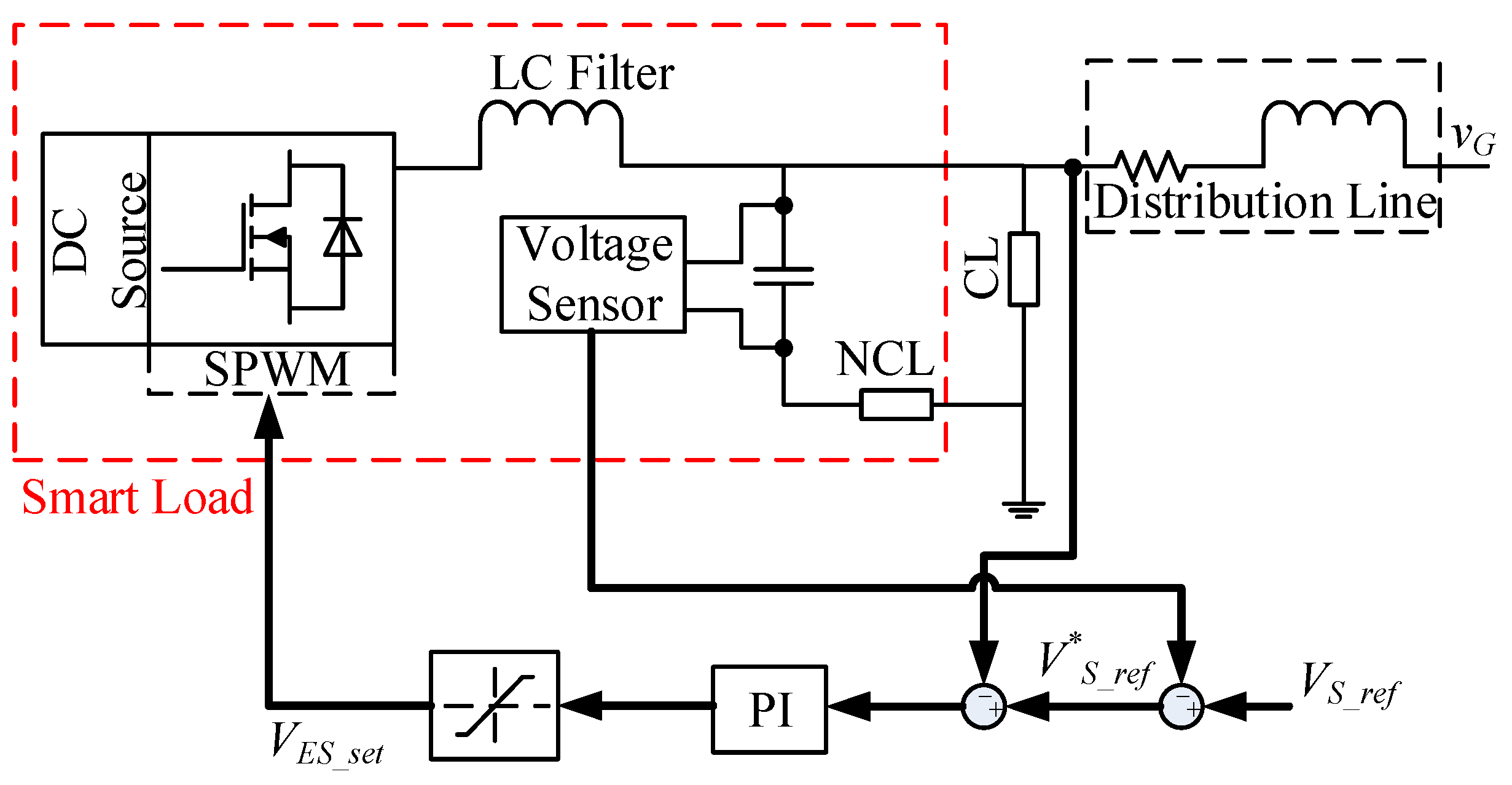
2. Control Strategies of ES-1
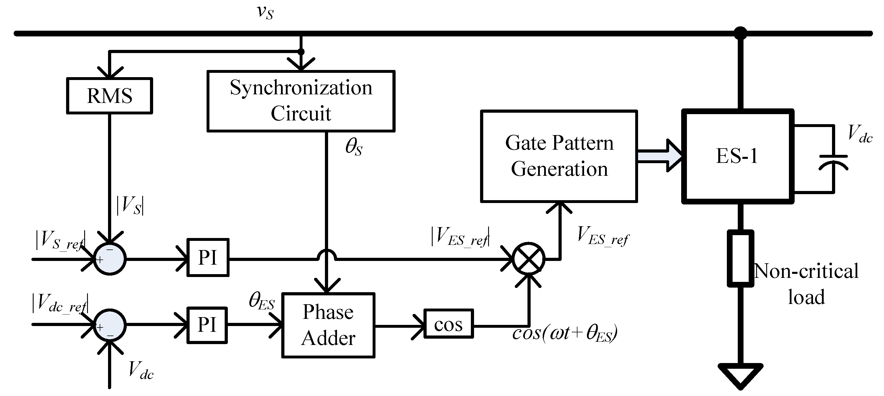
For ES-1 without an energy storage unit, the amount of reactive power injected from the power converter is controlled by a reference voltage whose vector is always leading or lagging the current vector by 90° [
6,
10]. A typical control scheme is depicted in
Figure 1 [
10].
The double PI closed-loop control, shown in
Figure 1, are adopted, to control the DC link voltage and the grid voltage. In order to ensure that there is no active power transferred between the DC link and the AC port of the ES, two coordinated closed-loops are used to regulate the DC link voltage
Vdc and also the magnitude of the grid voltage
vS. Therefore, the magnitude and phase of the ES voltage are interrelated and inherently controlled, and the degree of control freedom in the method is one. Under this control strategy, the power angle of the SL is not controlled and varies, during the grid voltage regulation process. The main advantage of this control strategy is that its structure is simple, which is easy to implement. Additionally, it does not need detection of the grid voltage and a priori knowledge of the circuit parameters. The shortcomings are also obvious. For example, the decoupling feature is weak, and it can only operate at the pure reactive power compensation mode, which causes an inability to adjust the power angle of the SL and can only stabilize the grid voltage.
3. Control Strategies of ES-2
Due to the inherent shortcomings of ES-1, most studies are focused on ES-2 and there are ready-made devices in the lab to test the performance of ESs. In a study by Kanakesh et al. [
11], ES is connected to an islanded single phase microgrid and simulated with two different control approaches, which are to regulate voltage and also frequency. The test results show that the ES employing just a reactive power compensation and involved in the regulation of voltage needs additional storage for ensuring stability. It has also been shown that ES with a reactive compensation adopted to support frequency regulation, aids in reducing the reserve storage capacity at the cost of poorer voltage regulation. The control method proposed by Mok et al. [
12] has been tested on a 2-kW small-scale power system. Simulation and experimental results show that the grid voltage regulation and the power factor correction of the SL can be performed simultaneously and independently without any mutual conflict on one another.
The ES-2 can enhance control flexibility by providing, both, active and reactive power with a degree of freedom that is one level higher than that of ES-1. Several typical control strategies for ES-2 have been list and analyzed in this section.
3.1. Single-Phase dq Decoupling Control Strategy
In ES-2, the current components of SL can be decoupled by the single-phase
dq transformation, and both the
d-axis and
q-axis currents can be controlled independently. However, if a coordinated control scheme is not provided, the magnitude of the
d-axis and
q-axis currents can be of any combination. This will cause conflict on the
d-axis and the
q-axis control loops when performing two adjustment functions, such as performing grid voltage and frequency regulation [
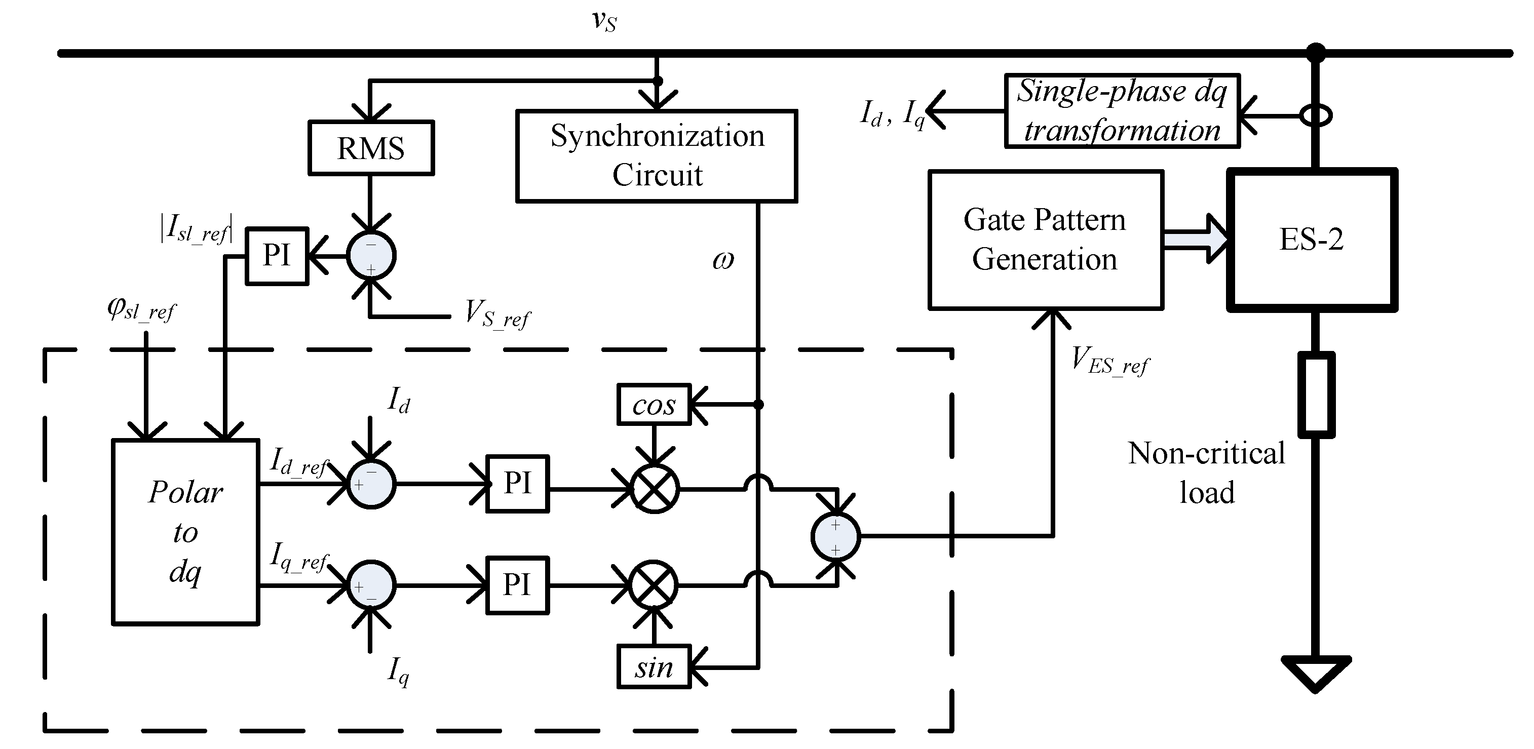
13]. In response to the problem, a current controller for ES-2 is proposed in [
12], as shown in
Figure 2.
Under this control strategy, the
d-axis and
q-axis current references are determined by the power angle reference
φsl_ref and the magnitude reference of the SL current |
Isl_Ref|, respectively. The current controller is shown in
Figure 2 within the dashed rectangle. The controller can only handle power factor correction in an open-loop manner and it lacks the ability to regulate the grid voltage. In order to achieve power factor correction and grid voltage regulation, a PI control loop must be added for closed-loop regulation of the grid voltage, which is shown in
Figure 2. It should be noted that when the power angle reference value
φsl_ref changes, both the
d-axis and the
q-axis currents have to be adjusted. Similarly, during grid voltage regulation, these two currents also change simultaneously. It means that there is still a mutual coupling of the two currents in such control, which is the critical disadvantage. Moreover, this control strategy needs a PI controller for grid voltage regulation and two additional PI controllers to regulate the
d-axis and the
q-axis currents. Three sets of PI controllers in total make it a large amount of work for parameter designing and debugging.
3.2. Radial-Chord Decomposition Control Strategy
From the perspective of power flow, the control schemes above either directly controls the power flow of the converter itself or indirectly controls the power of connected circuits and loads. For example, when applying the
dq transformation on the
d-axis and the
q-axis current control loops, the ES can directly and independently control the active and reactive powers of the ES, which are hereafter designated as
PES and
QES, but it cannot directly control the power flow through the entire SL [
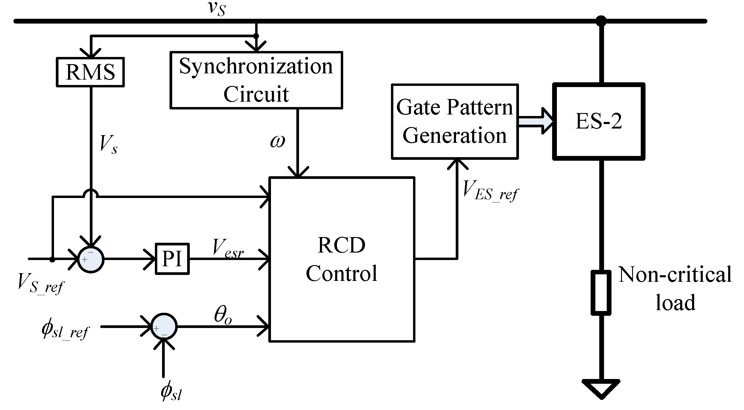
9]. Therefore, it is unable to realize the achievement of two control targets completely (such as the CL voltage and the power angle of the SL) by a single ES. The radial-chordal decomposition (RCD) control proposed by Mok et al. [
12] can directly control the active and reactive powers of the SL, by means of the control block diagram shown in
Figure 3.
The idea behind the RCD control is to decompose the ES voltage into a chord component and a radial component in phase or anti-phase with the NCL voltage. The influence of the two components on the system has been well-studied by Mok et al. [
12]. When analyzing the influence of the chord component, it is assumed that (i) there is no radial component, and (ii) the magnitude of the grid voltage is always equal to the nominal reference value (e.g., 220 V). By the chord component control, the NCL voltage and the grid voltage are always equal in magnitude. When analyzing the influence of the radial component, it is assumed that (i) there is no chord component, and (ii) the radial component is in phase or in anti-phase with the NCL voltage. It is concluded that the chord component is related to the power angle of the SL, whilst the radial component is related to the apparent power of the SL, both of them being completely decoupled in mathematical relationship, thereby, achieving simultaneous control of the two targets. In the control process, when the grid voltage fluctuates, the apparent power of the SL is indirectly controlled by adjusting the radial component to realize power balance between the power generation and the load demand. When the grid voltage rises and the CL voltage is higher than the reference value, the total apparent power tends to decrease; otherwise it increases.
RCD control requires the a priori knowledge of the internal parameters of the SL, such as the impedance angle of the NCL. This facilitates the embedding of the RCD controller in a separate device, such as a heater and a refrigerator. Furthermore, as shown in
Figure 3, an advantage of the RCD strategy is that the grid voltage regulation can be performed using only one PI control loop, while the power factor can be controlled in an open-loop manner. This is not possible by the
dq transformation method shown in
Figure 2. However, the RCD control strategy has its shortcomings. For instance, the algorithm is more complicated, and the control of ES-2 is difficult under a pure reactive power compensation mode.
3.3. δ Control
The
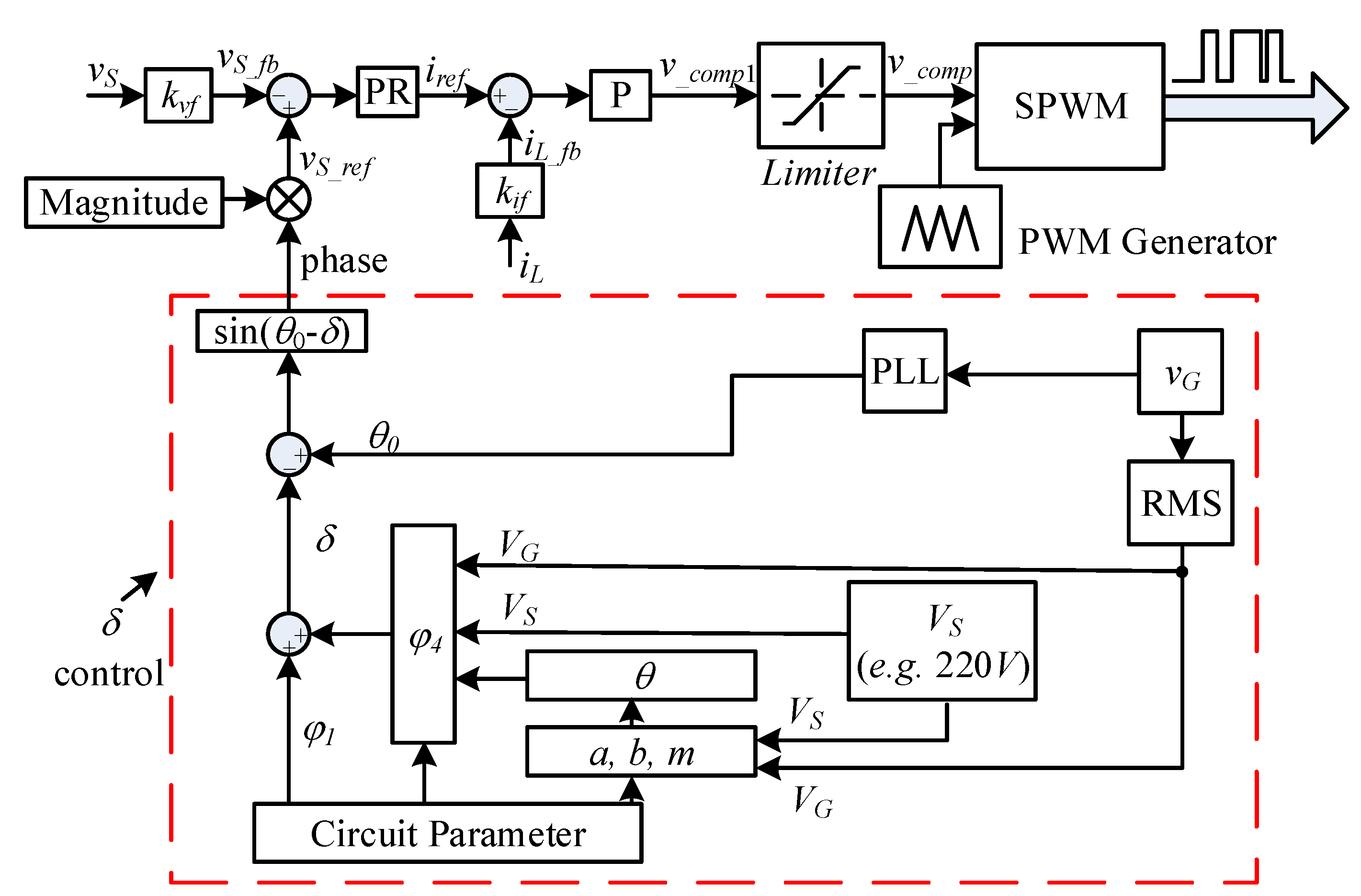
δ control proposed by Wang et al. [
14] is shown in
Figure 4. It has a proportional resonant (PR) controller for the external grid voltage loop and a proportional (P) controller for the internal inductor current loop.
δ control is performed by controlling the instantaneous phase angle of the PR controller to achieve four typical compensations that the ES can support, namely, (1) pure reactive power compensation, (2) specified power factor compensation, (3) constant power compensation, and (4) constant reactive power compensation.
In
Figure 4,
vS is the instantaneous CL voltage, and
vS_fb is the feedback voltage detected from
vS, multiplied by the coefficient
kvf (e.g., 0.1). The signal
vS_ref is a predefined sinusoidal reference voltage whose amplitude is given as needed and whose phase is lagging
vG (power generation side voltage) by
δ. The voltage error is used to generate a reference value for the current loop through the PR controller.
iL_fb is obtained by multiplying the current
iL detected from the inductance by the coefficient
kif (e.g., 0.1). The current error is used to generate a modulated signal
v_comp through the P controller and the limiter. The PWM generator generates four drive signals.
The four typical compensations supported by the ES under the
δ control are essentially the different phase relationships between the ES voltage and the ES current. A vector diagram for different situations has been depicted by Wang et al. [
14] and then steady state algorithm for
δ calculation is derived. With the
δ control, the operating mode of the ES can be automatically determined according to a different point of common coupling (PCC) voltages, and the same algorithm can be used for all compensation when the reactance in the NCL changes while the real part remains unchanged. Regardless of the nature of the CL and NCL, ES can operate in capacitive, resistive, and inductive modes. Obviously, the most important part of the control loop is the
δ control, which directly affects the reference value and the control targets.
The
δ control is based on the vector diagram. The circuit parameters that need to be known in advance are impedance of the CL, impedance of the NCL, the resistance and inductance of the distribution line, the effective value of the voltage on the demand side, the effective value of the voltage on the power generation side, and the phase information. It is difficult to adopt
δ control in actual applications since the power generation side is far away from the demand side. As a result, a communication technology is required between two adjacent ESs, which inevitably leads to an increase in cost. In addition, the mathematical expressions of the parameters
a,
b, and
m in the
δ control scheme are different in the case when CL and NCL are pure resistance, resistive-inductive, and inductive-capacitive, which increases the complexity of the controller design. Additionally, as the PR controller only keeps an infinite gain at the resonant frequency, the control accuracy is sensitive to the grid frequency deviations [
15].
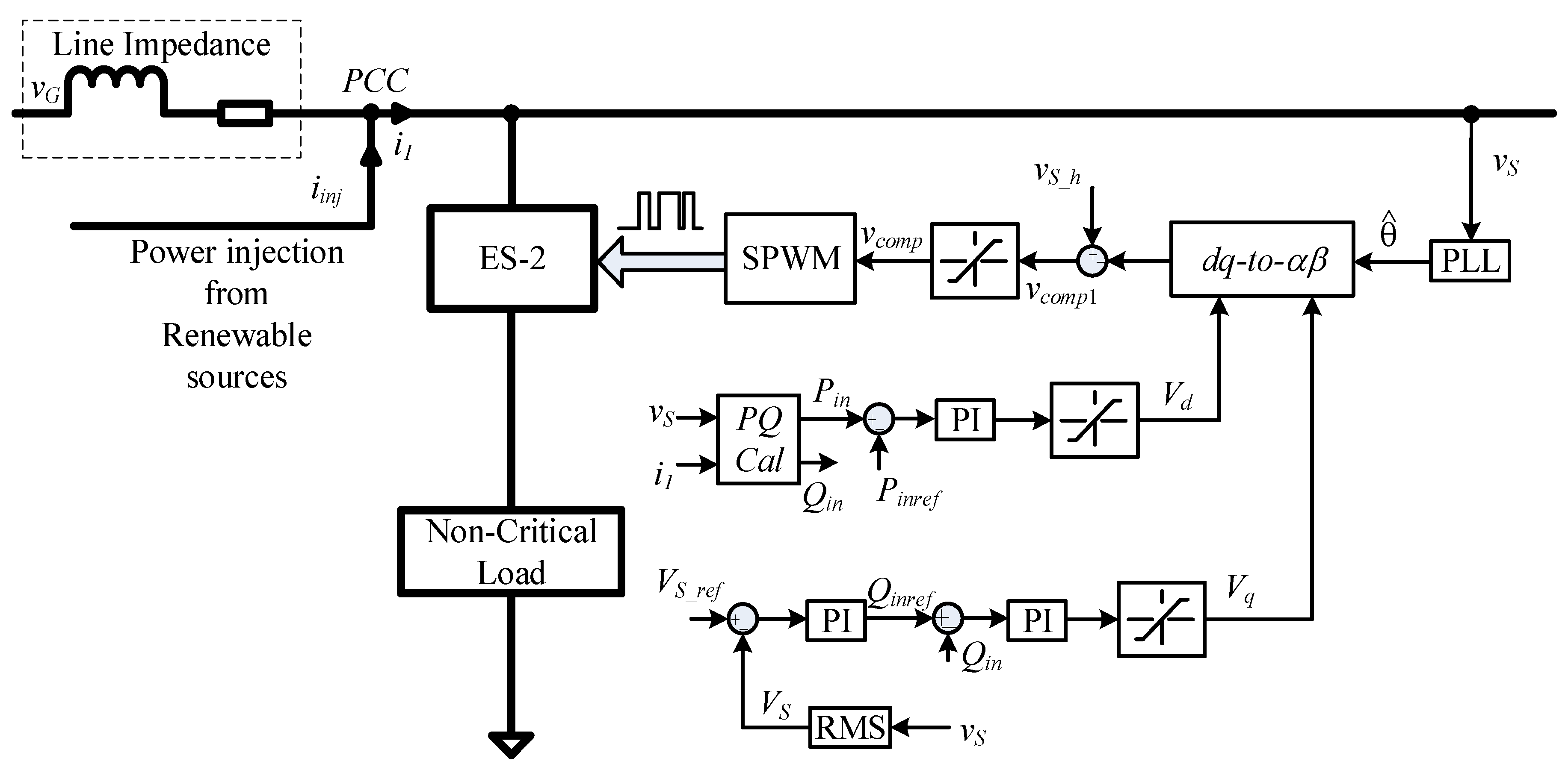
3.4. Power Control Strategy
Maximum power point tracking (MPPT) technology is commonly used in wind or solar power plants, and the tracked active power is consumed by the electrical load at domestic home, which can be classified into CLs and NCLs. For ES installed in the same position as the wind power plant, even if the equipment changes rapidly, the active and reactive power generated can be measured by the ES. To control the input active power at a fixed value, the aforementioned control methods cannot be realized except in the phase-control method. The shortcomings of the phase control are obvious, almost all circuit parameters are required, which is not applicable when the power side and the power generation side are far apart. Therefore, a simple power control strategy has been proposed by Wang et al. [
16], which enables simultaneous control of input active power and reactive power.
From the PCC to the right, in
Figure 5, which has been adopted from Wang et al. [
16], active power, reactive power, and apparent power can be represented by Equations (1)–(3), where
Pin and
Qin represent the total active power and reactive power of the ES system, respectively.
denotes the apparent power.
where
According to [
17], the active and reactive powers can be represented in terms of the variables on a rotating frame as follows.
where
vd and
vq are the components of
vS in the
dq rotating frame, and the
id and
iq are the components of
i1 in the
dq rotating frame.
At this step, the active power and the reactive power are decoupled. In actual control, the d-axis controller controls the Pin and the q-axis controller controls the Qin. If the control target is to regulate CL voltage instead of Qin, then the loop outside the q-axis will be added to the PI controller and its output will represent the reference to Qin, designated as Qinref.
The control strategy is simple, which has little dependence on the circuit, and can realize any two control targets among the active power, reactive power, and the critical load voltage. However, it is not decoupled completely.
3.5. Summary of the Control Strategies of ES-2
Currently, the above strategies are the mainstream control strategies for ES-2, in addition to these, there are some other control strategies. All the control strategies discussed above are based on voltage-source inverter (VSI) and voltage control, a novel control strategy of direct current control with harmonic suppression function has been proposed by Wang et al. [
18], which uses a current-source inverter (CSI) to improve the performances of ESs. Compared to the VSI, direct current control can be adopted for CSI, which works as a boost-type inverter for DC-AC power conversion [
19,
20,
21]. So far, many studies on SLs with ES are focused on the voltage fluctuation at PCC. A simple two-step approach of voltage and frequency control has been proposed by Yang et al. [
22] to handle the fluctuations of both voltage and frequency. Some modern and adaptive controllers, such as fuzzy logic controller [
23] or an Artificial Neural Network have been adopted in ESs to replace the PI controller. It has been proved that the fuzzy logic controller is more precise, with less design complexity, according to the curve of the voltage across the NCL [
24].
To better understand the control strategies of ES-2, a brief summary has been provided to describe the comparisons between the existing typical control strategies, as shown in
Table 1.
4. Control Strategies of ES-3
At present, there are few studies on ES-3, most of which have been carried out on ES-2. However, the research on the control of ES-3 is very practical. The reason is that ES-2 needs to be connected in series with the NCL, which is not consistent with the connection type of traditional power system. In contrast, ES-3 avoids such disadvantage. In theory, the power control strategy used by Wang et al. [
16] can also be applied to the ES-3. However, the voltage regulation of the CL is limited to a small range.
4.1. Active-Reactive Power Decoupling Control
ES-3 has been proposed by Lee et al. [
8], while the control block diagram is shown in
Figure 6 which has also been adopted from [
25].
Pref and
Qref are reference values of active power and reactive power, respectively, which are decoupled by the
dq transformation, as shown in Equation (8).
The frequency adjustment and voltage stabilization are determined by Pref and Qref, respectively. The frequency reference fref and the grid voltage reference VS_ref are provided to the controller as the predefined values.
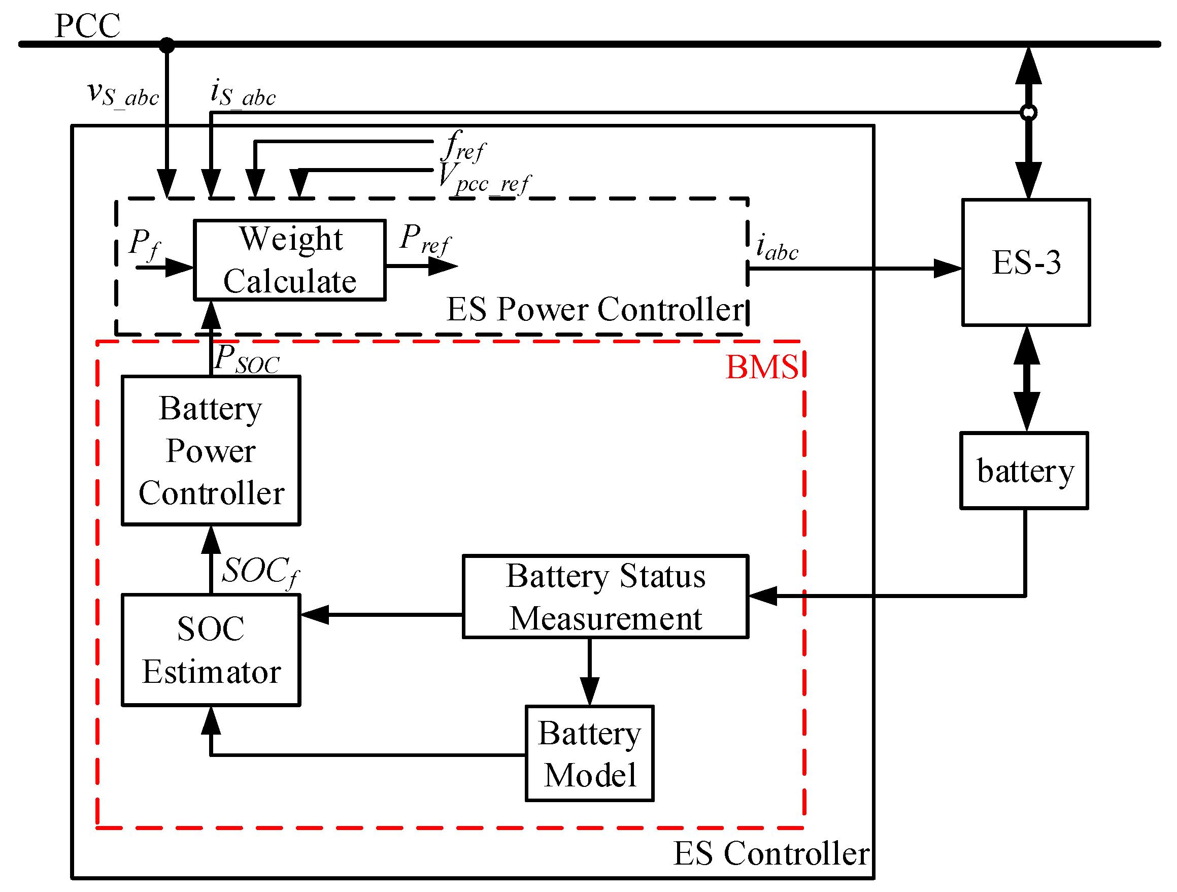
4.2. Control Strategy with Battery Management System
The DC link in ES-2 has an energy storage unit, such as a battery. Due to the limited battery capacity, it is necessary to consider changes in the state-of-charge (SOC) so that the battery will not be over-charged or over-discharged. It has been revealed by Yang et al. [
25] that when the load power on the demand side increases at a certain moment, the ES must provide a certain active power during the transient to regulate the frequency at the reference value. However, after the transient, the ES still continued to provide active power. In other words, if there is no mechanism for managing the ES to provide an active power, the battery will be fully discharged for a long time. In response to this problem, a battery management system (BMS) is added for the auxiliary control in [
25], as shown in
Figure 7.
In
Figure 7, an instant SOC signal
SOCf, which is normalized from 0 to 1, is introduced. In this case,
SOCref is set to 0.5, which is to maintain the battery at 50% state of charge so that it can easily absorb or deliver active power for grid regulation. There are two factors that determine the active power reference value of ES-3, namely
Pf and
PSOC, where
Pf is a signal that controls the active power provided or absorbed, in order to adjust the frequency, and
PSOC is a signal that controls the SOC of the battery storage system. The actual active power reference signal
Pref is the weighted sum of these two signals, as given by Equation (9).
It is obviously seen that when the weight of PSOC is 0, the control strategy is exactly the same as the original control strategy. The ultimate goal is to achieve a slow charge or discharge rate when the instantaneous SOC is close to 0.5; otherwise, the charge and discharge rate will be fast. With the automatic charging and discharging strategy integrated in the active power control loop, ES-3 is expected to improve the quality of the grid in the long run and has a higher stability. This concept can also be applied to other versions of the electric springs.
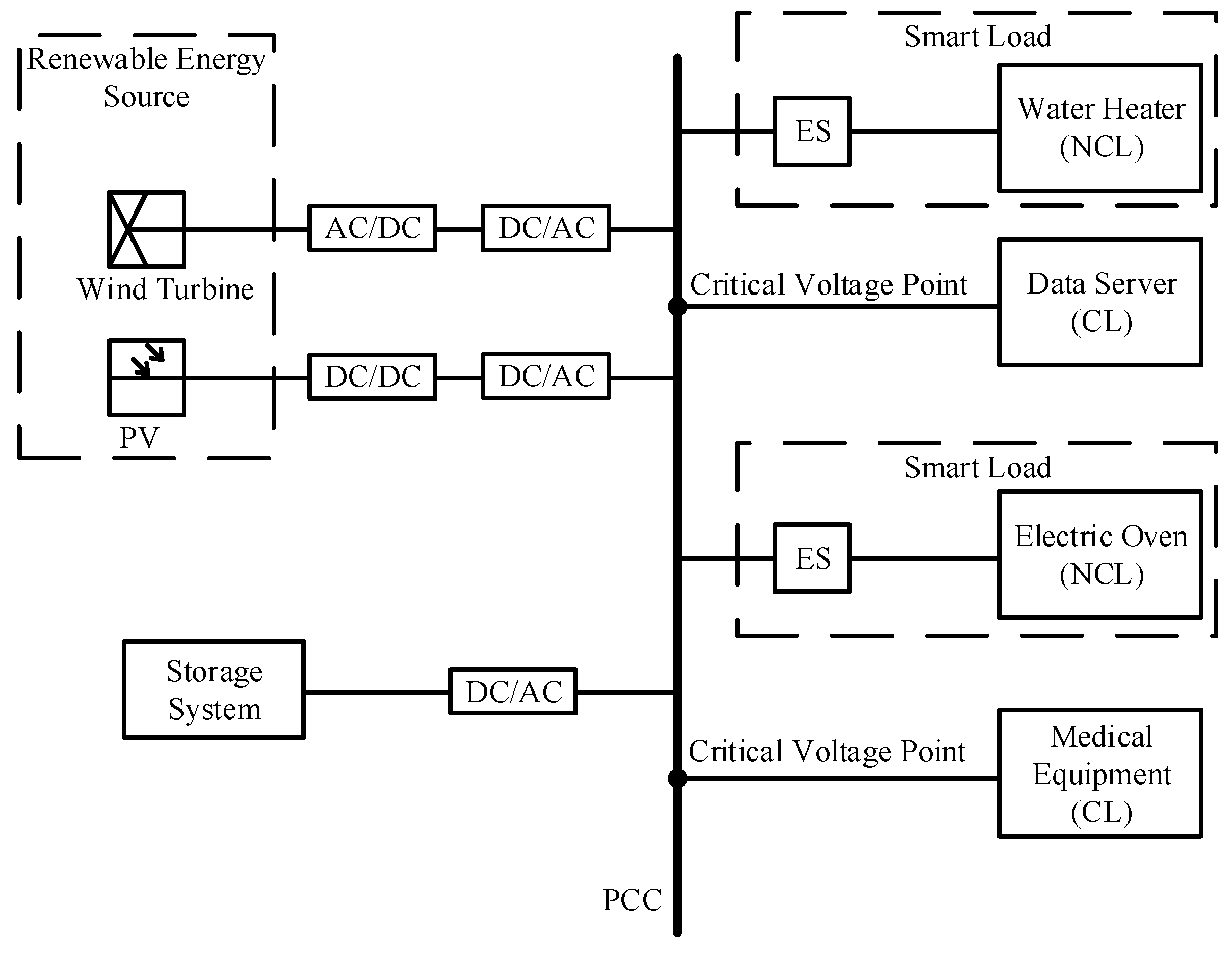
5. Control Strategy for Distributed ESs
The various control methods currently available can explain that a single ES plays a role in stabilizing the CL voltage and improving power quality, but the ES design was originally intended to support CL voltage at various installation points of the grid. As shown in
Figure 8, the microgrid contains many ESs in a distributed manner. The limited range of NCL voltages will limit the operating range of a single ES. If the control of a large number of ESs can be coordinated, these ESs can provide effective support for the microgrid. In order to implement the plug-and-play functionality of ESs, distributed control strategies are necessary so that they can support the voltage at their location while taking voltage variations along the distribution line into account. In response to this situation, Lee et al. [
26] introduced the idea of a droop control in the ES motor and tested it on a distributed line using three 1 kVA ESs, demonstrating that distributed ESs can be coordinated through a droop control to minimize the total reactive power injection.
The advantage of a droop control is that only local information is needed, and the mathematical expression of the Q-V droop control of the generator is provided as follows.
where
V,
V*,
n and
Q are the output voltage, the standard voltage, the droop coefficient, and the output reactive power, respectively.
In order to realize the droop control of the SL, an improved droop control has been proposed by Lee et al. [
26], which can be derived from Equations (11) and (12), as follows:
where
KP,
KI and
K are proportional gain, integral gain, and the droop coefficient, respectively. The droop coefficient
K is selected based on the maximum reactive power of the ES.
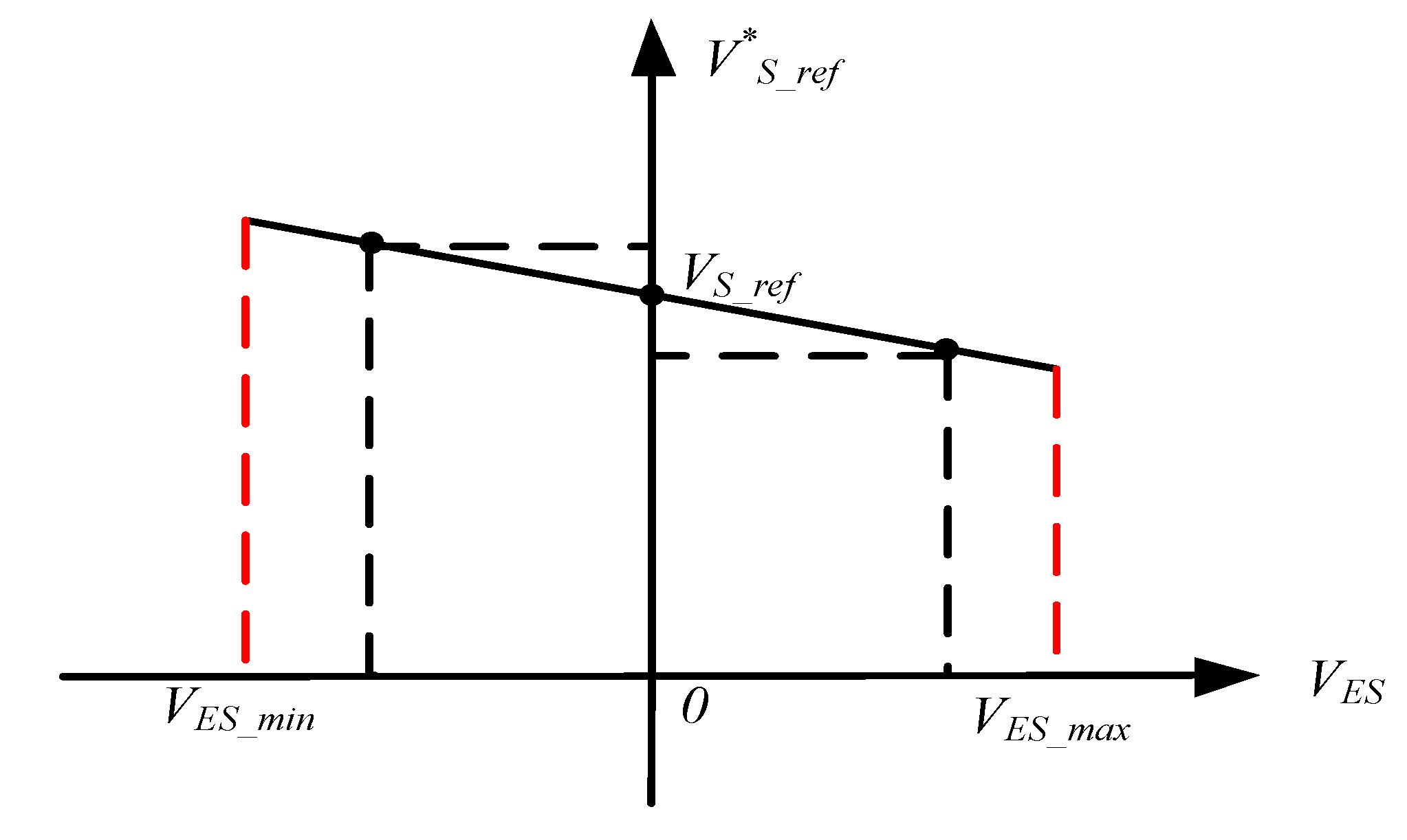
Figure 9 shows the droop curve of Equation (11), which has been adopted from Chen et al. [
27]. As the ES voltage changes, the reference value of the CL voltage will move around the standard voltage point.
Figure 10 is a complete control block diagram of the droop control, which has also been adopted from Chen et al. [
27]. The modified reference voltage
V*S_ref is used as a new voltage set-point. The SL is then operated to adjust the CL voltage
VS, at the voltage set point of the offset.
Since the PI controller has no steady-state error for the DC signals, for all ESs under steady-state conditions,
substituting Equation (13) into Equation (11), yields,
It is revealed by Equation (14) that, at the steady state, the CL voltage error is a linear function of the ES voltage. Excessive compensation or insufficient compensation of
VES can cause local CL voltage errors. When an ES has a positive voltage error and nearby ESs have a negative voltage error, they might operate in the opposite way to regulate the CL voltage. For instance, one SL operates at an inductive mode (reactive power consumption) and the other SL operates at a capacitive mode (reactive power injection). At the same time, a high droop gain
K is usually required to ensure a reactive power sharing [
28]. However, as shown by Equation (14), a high value of
KVES will result in a large CL voltage error. In order to eliminate the steady-state error,
K is limited to a small range, which in turn affects the sharing of reactive power between the ESs.
6. Conclusions
In this paper, the control strategies of several typical topologies have been analyzed and summarized for the single-phase ESs, such as dq decoupling control, RCD control, δ control, droop control, etc. Considering the advantages and disadvantages, there is almost no perfect control strategy, at present. It can be imagined that the application of ESs in the microgrid has very promising prospects. If simpler and more optimized control strategies are found in the future, it will inevitably promote its productization and application, and play a huge role in the field of distributed generation, especially in the intelligent energy management in household applications, with power generation from RESs. It should be remarked that great interests have been seen on the topologies and control strategies of single-phase ESs, and this paper only focuses on the main control strategies for their main topologies. To promote the application of ES, new topology of the ES should be studied which still contains NCL but does not need to be connected in series with it. Additionally, before implementing the ESs to the larger scale real-time power systems, it is necessary to make a reliable large-capacity prototype from the engineering point of view, taking its performance, cost, and practicality into account.


