Experimental Study on the Performance of Polyurethane-Steel Sandwich Structure under Debris Flow


Abstract
1. Introduction
2. Test Setup and Procedure
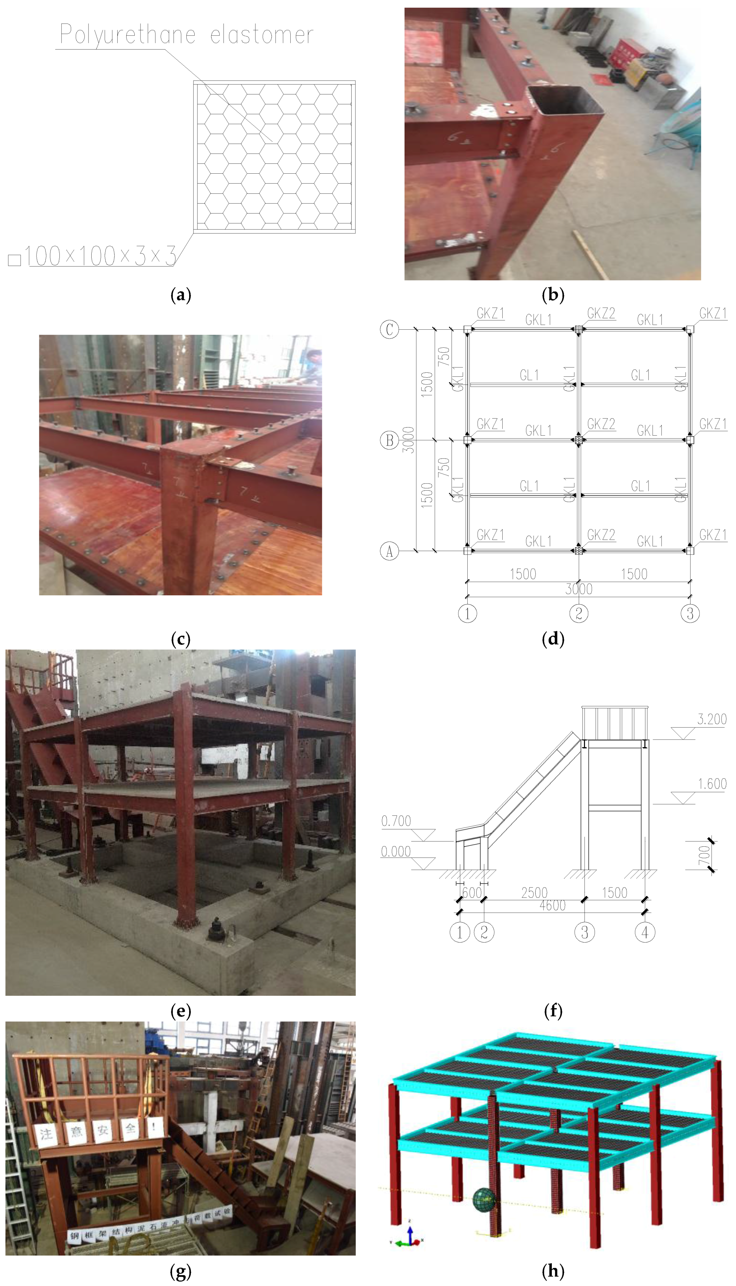
2.1. Test Model
2.2. Test Loading Schedule
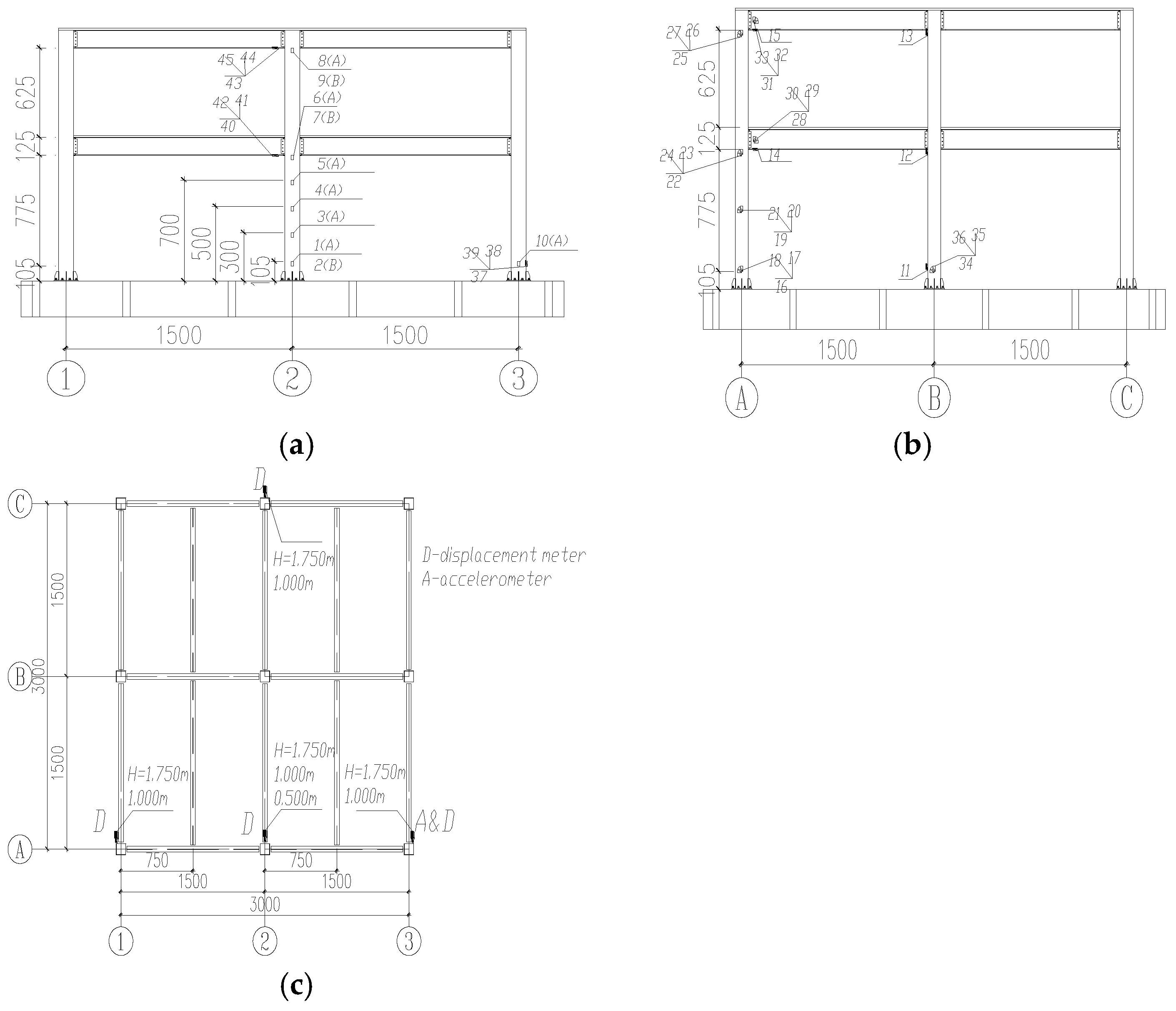
2.3. Instrumentation Arrangement
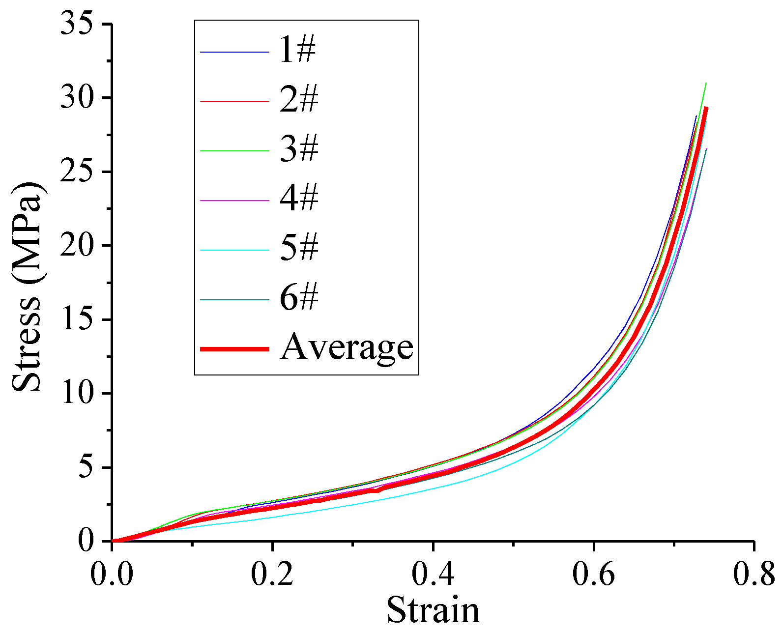
2.4. Polyurethane Property Test
3. Test Phenomena and Analysis
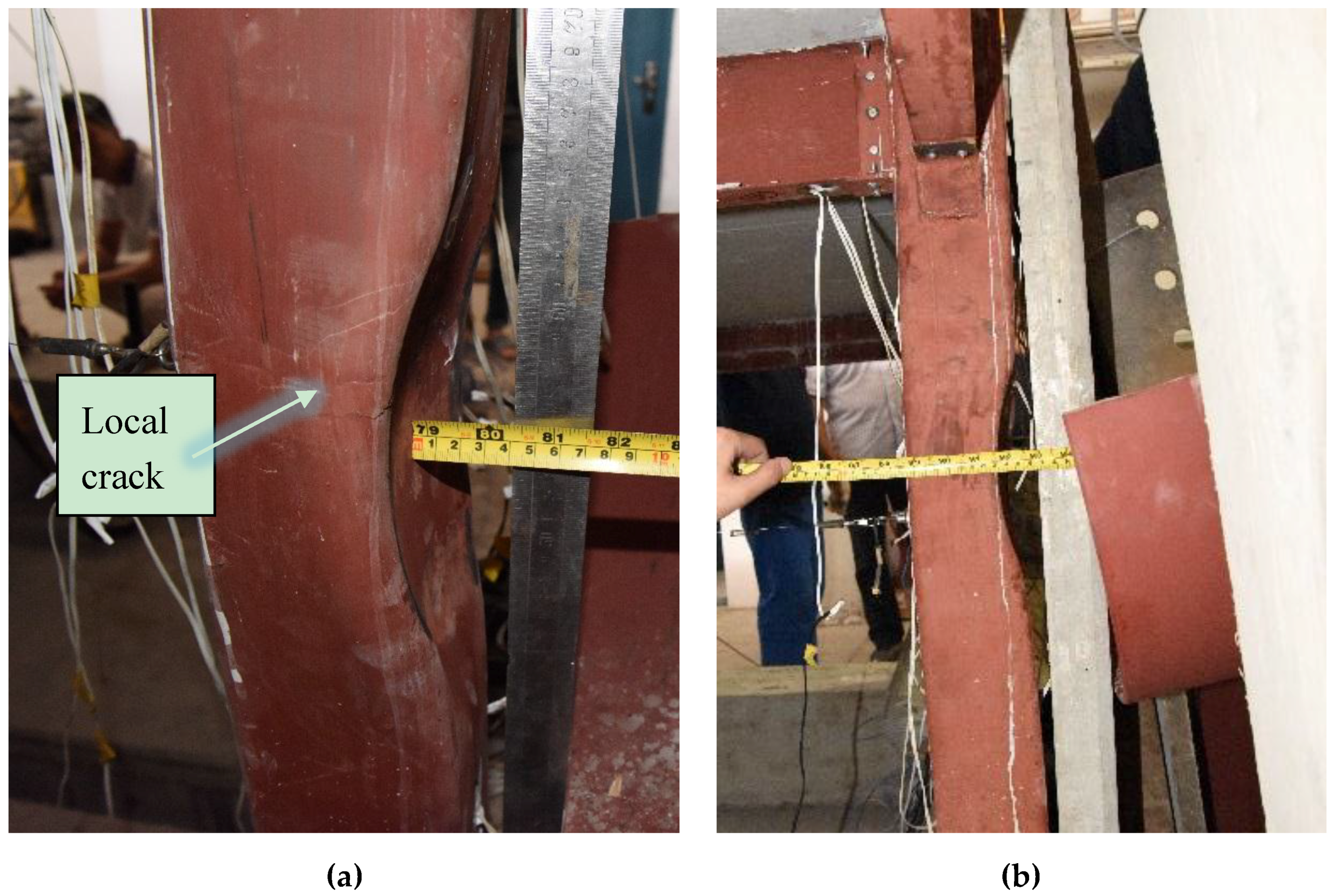
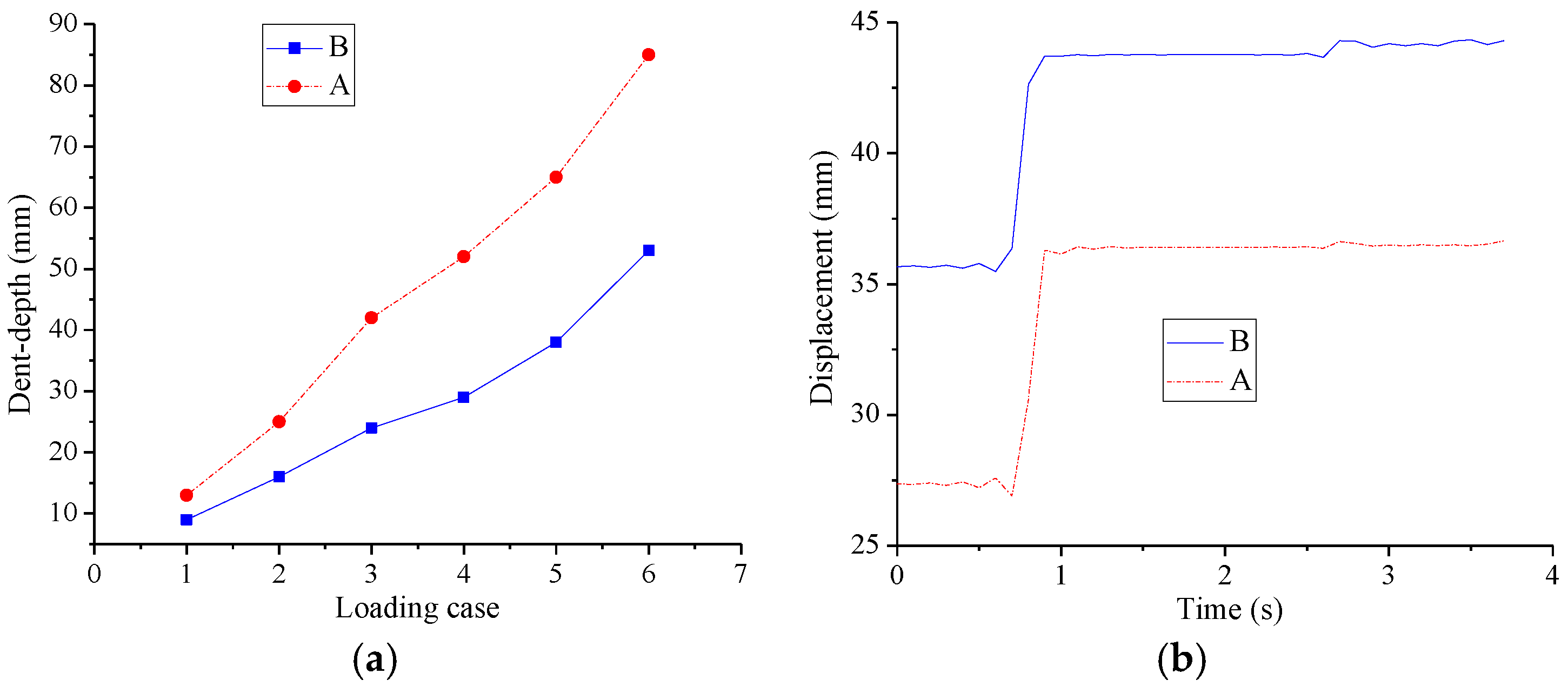
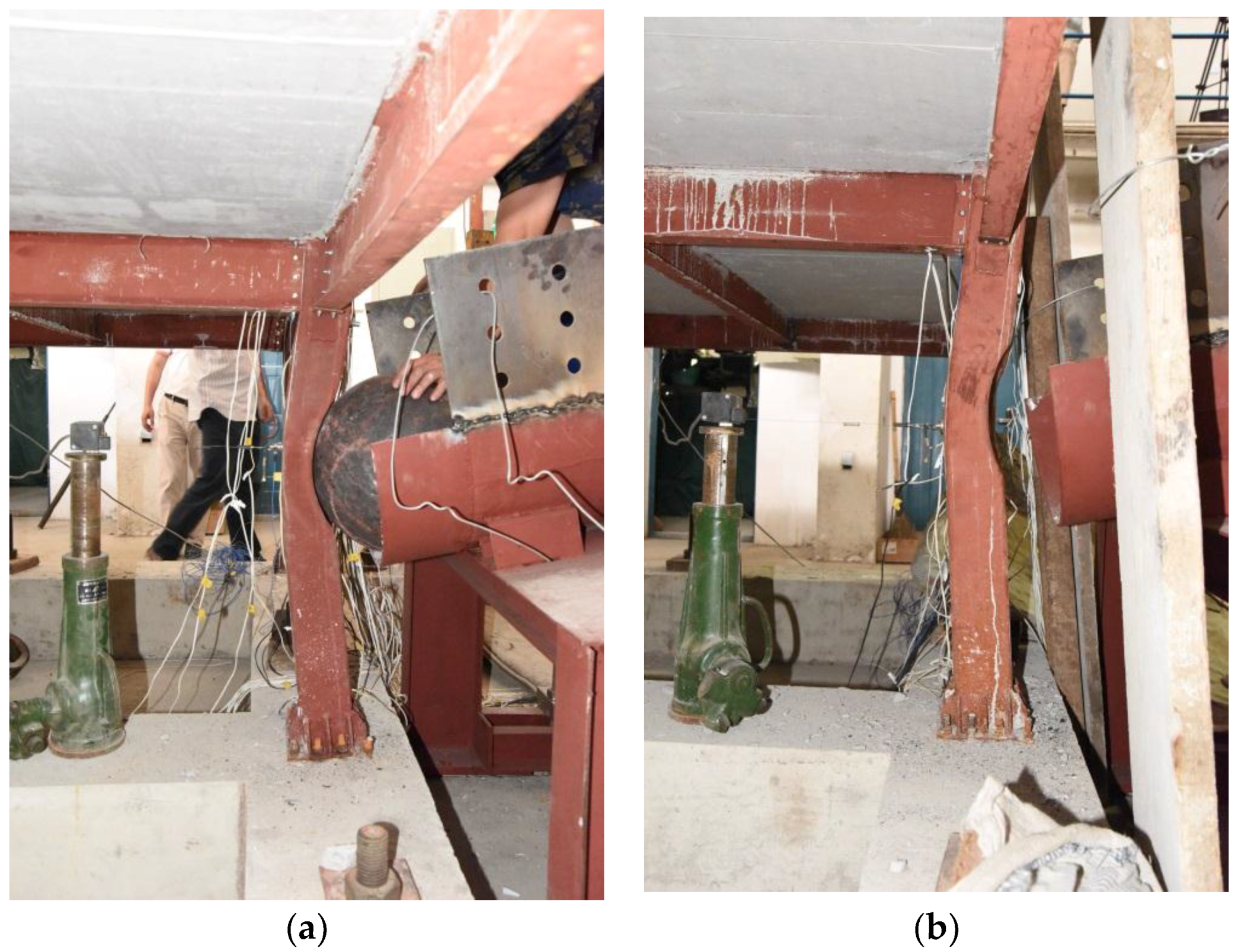
3.1. Response of the Impacted Column
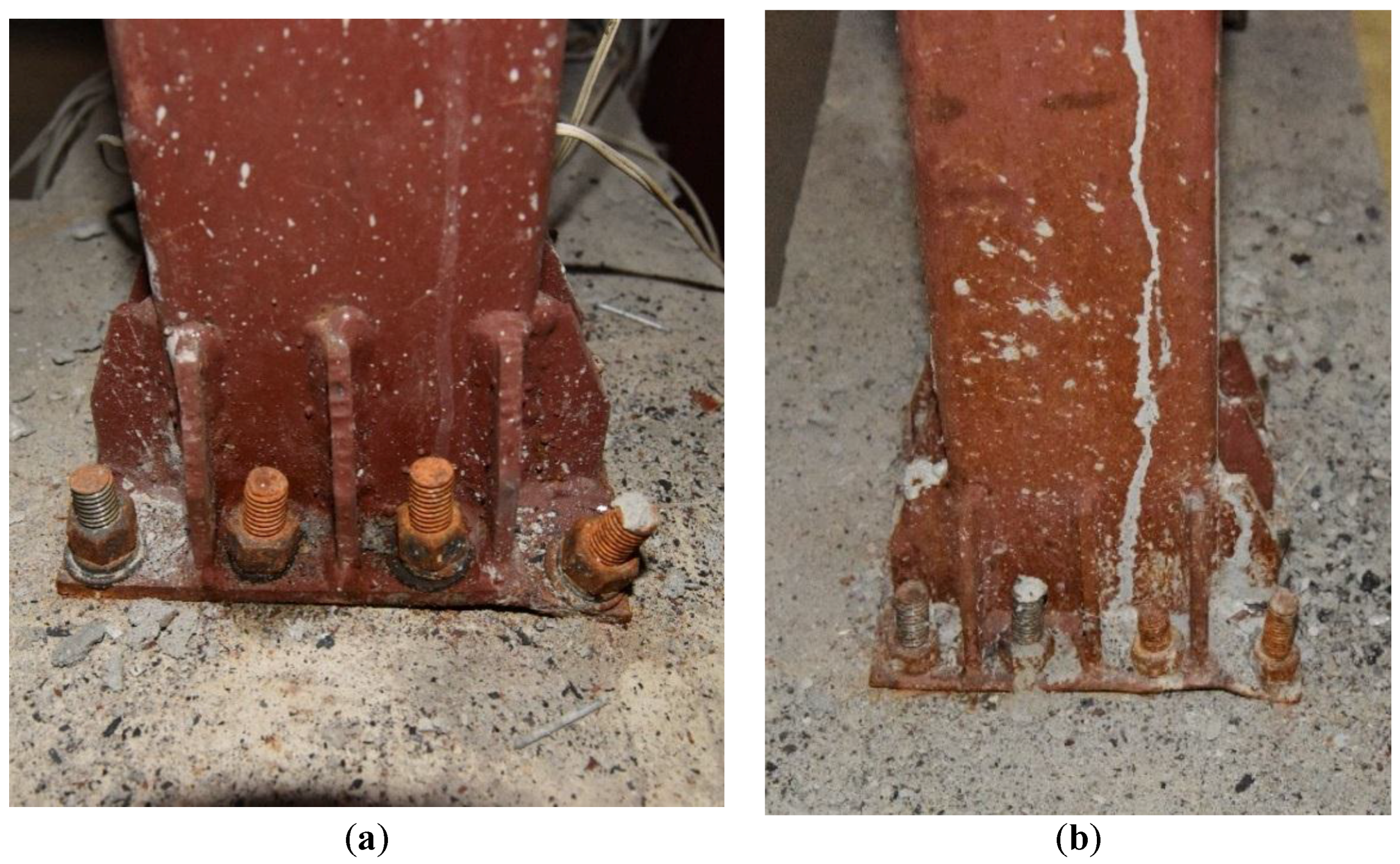
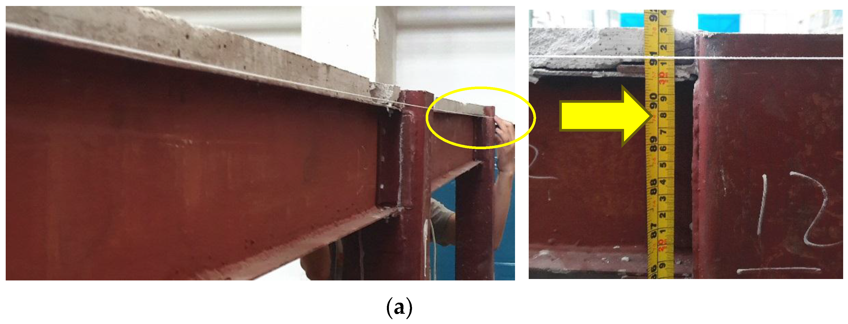
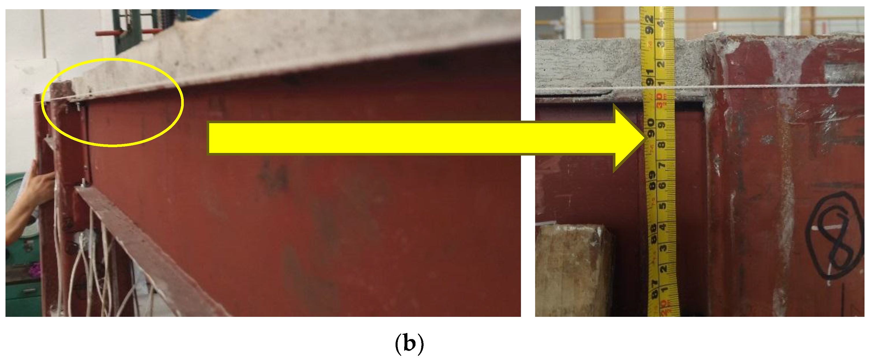
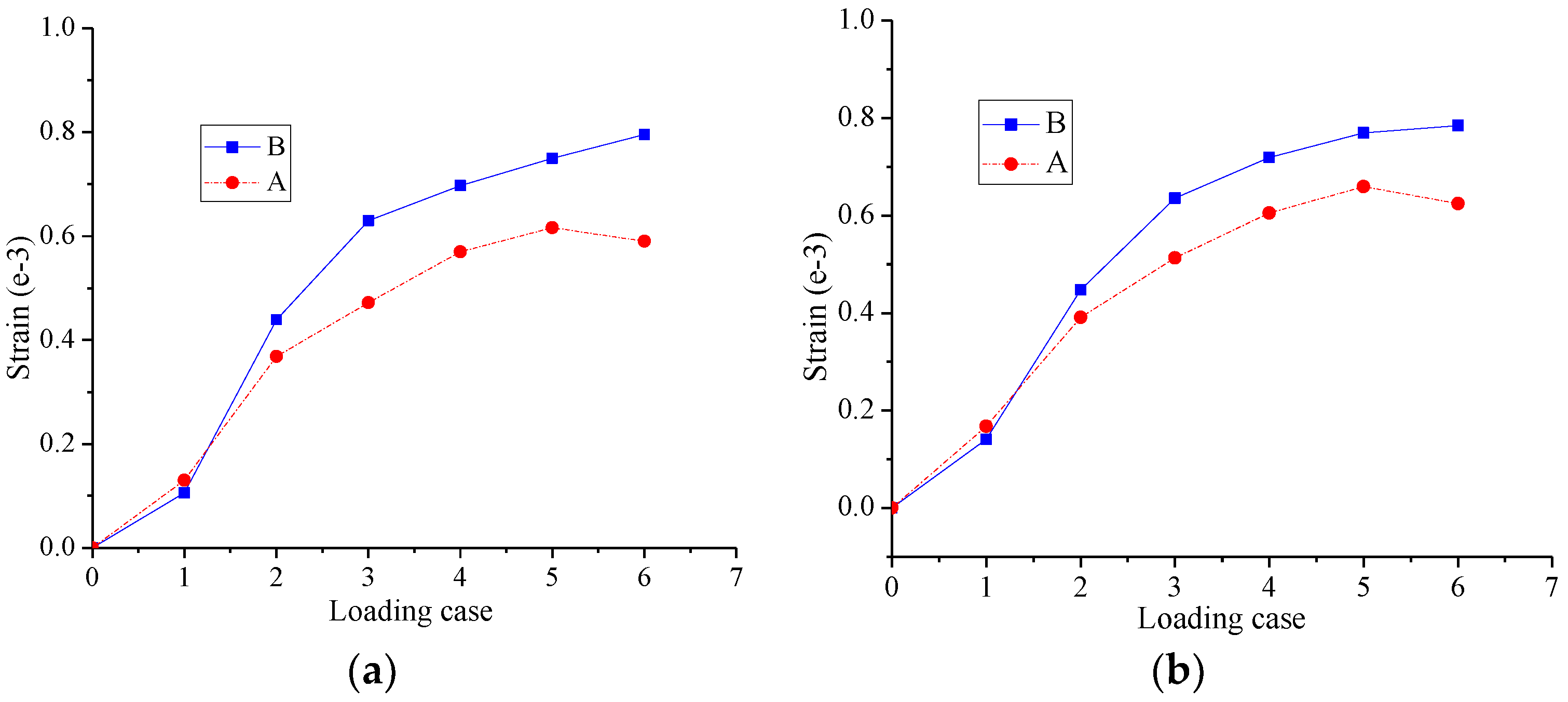
3.2. Local Deformation of Joint
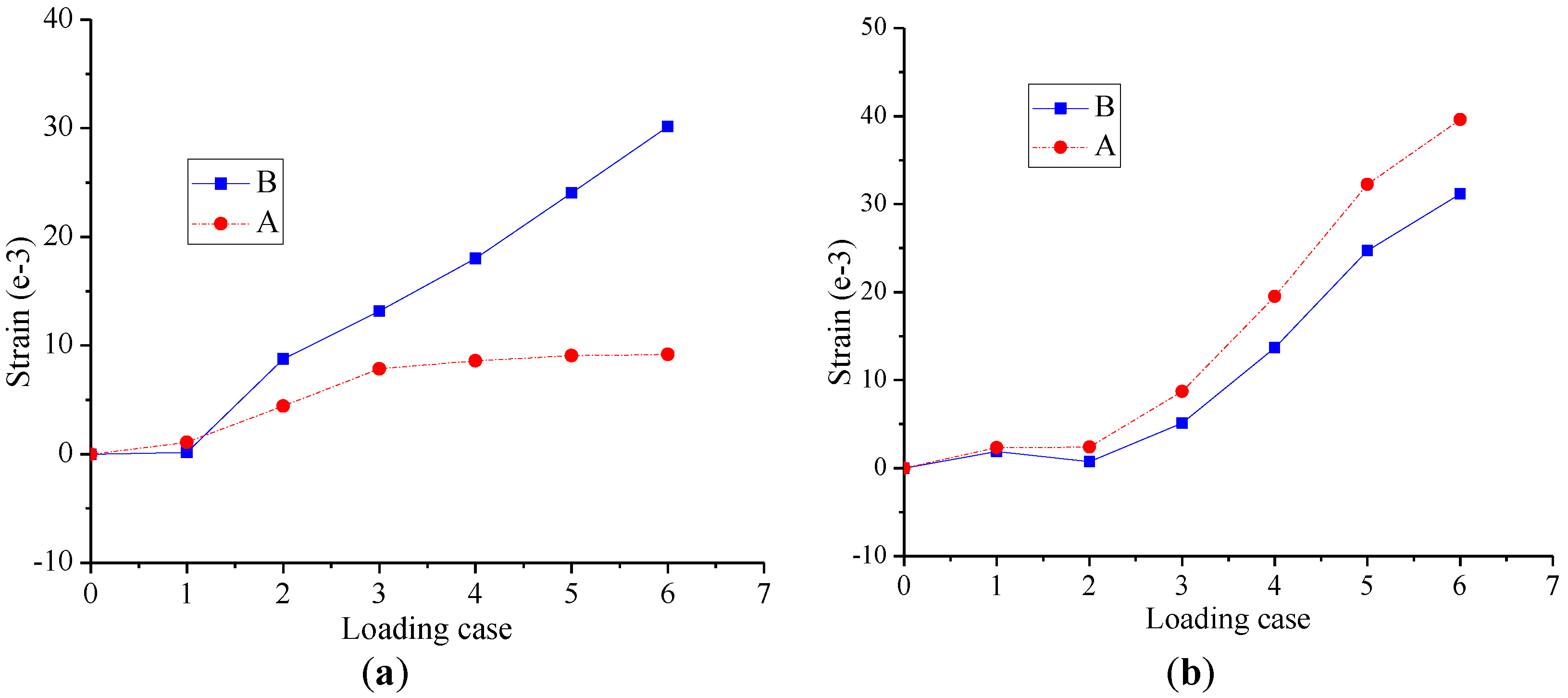
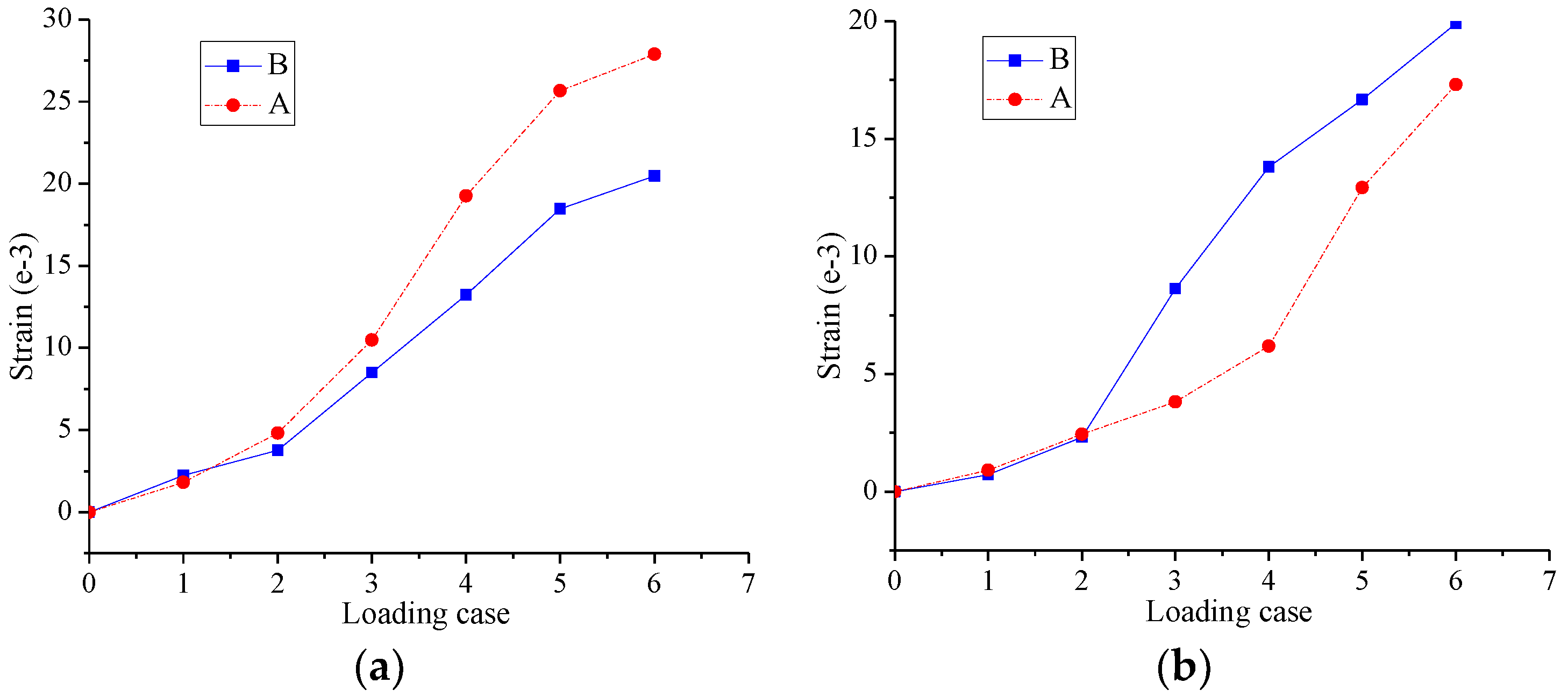
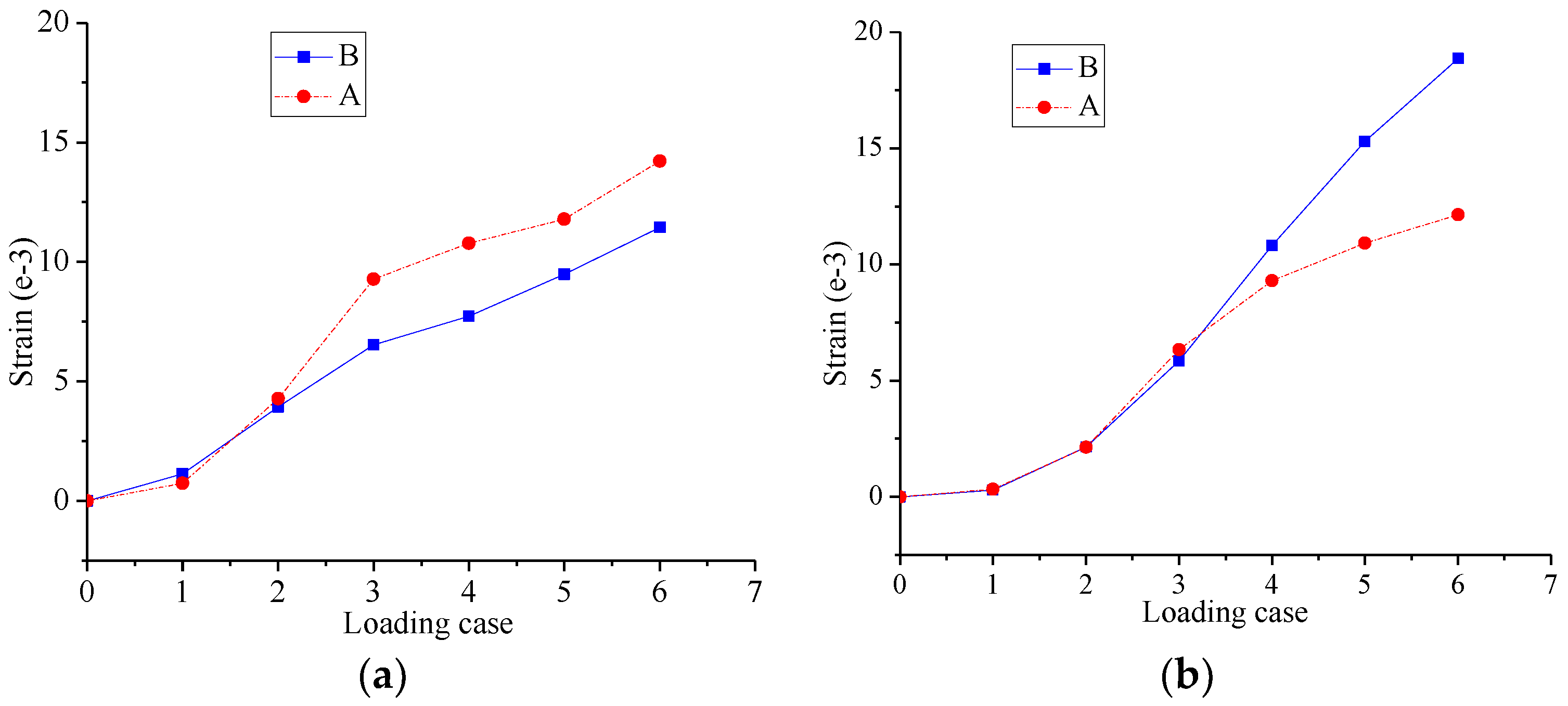
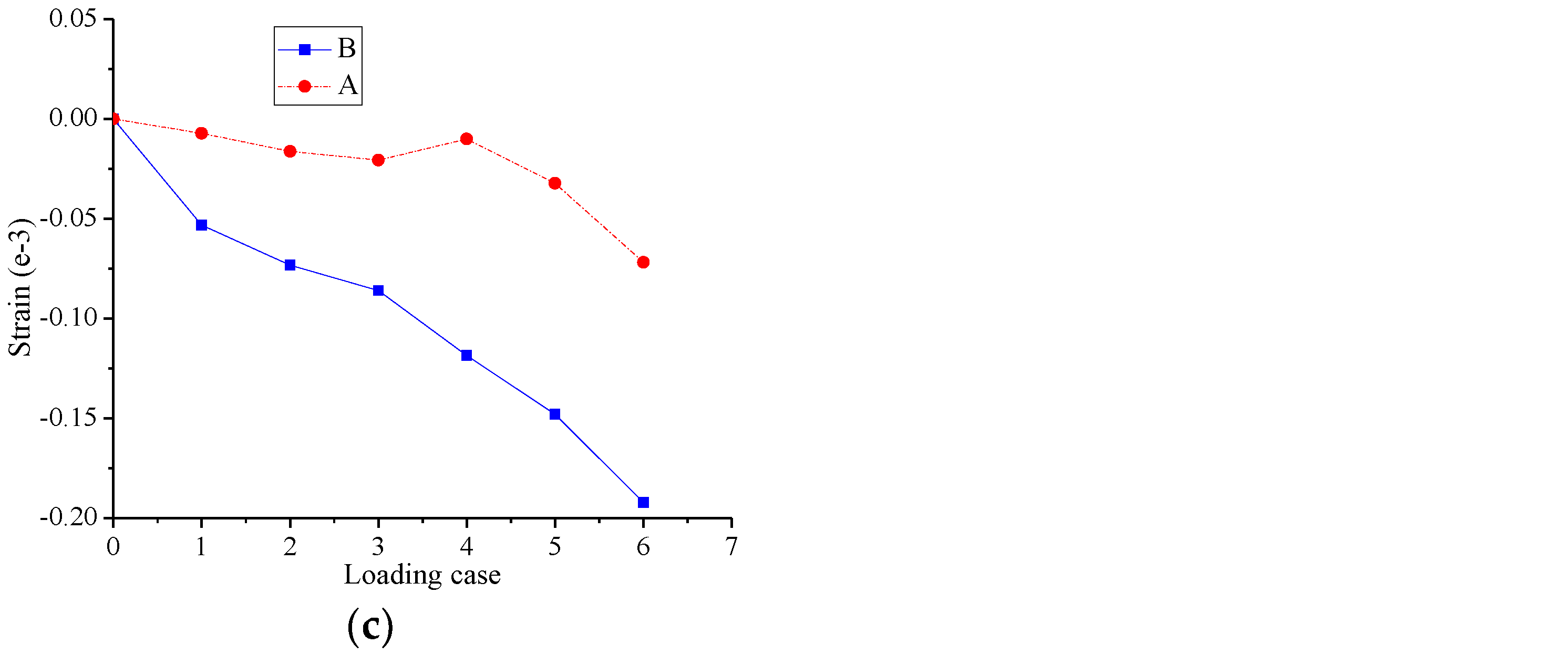
3.3. Overall Structural Deformation
4. Conclusions
Acknowledgments
Author Contributions
Conflicts of Interest
References
- Iverson, R.M. The physics of debris flow. Rev. Geophys. 1997, 35, 245–296. [Google Scholar] [CrossRef]
- Hu, K.H.; Cui, P.; Zhang, J.Q. Characteristics of damage to buildings by debris flows on 7 August 2010 in Zhouqu, Western China. Nat. Hazards Earth Syst. Sci. 2012, 12, 2209–2217. [Google Scholar] [CrossRef]
- Zanchetta, G.; Sulpizio, R.; Pareschi, M.T.; Leoni, F.M.; Santacroce, R. Characteristics of May 5^6, 1998 volcaniclastic debris flows in the Sarno area (Campania, southern Italy): Relationships to structural damage and hazard zonation. J. Volcanol. Geotherm. Res. 2004, 133, 377–393. [Google Scholar] [CrossRef]
- Chen, X.Z.; Cui, Y.F. The formation of the Wulipo landslide and the resulting debris flow in Dujiangyan City, China. J. Mt. Sci. 2017, 14, 1100–1112. [Google Scholar] [CrossRef]
- Wang, W.X.; Hua, X.G.; Wang, X.Y.; Chen, Z.Q.; Song, G.B. Optimum design of a novel pounding tuned mass damper under harmonic excitation. Smart Mater. Struct. 2017, 26. [Google Scholar] [CrossRef]
- Song, G.B.; Zhang, P.; Li, L.Y.; Singla, M.; Patil, D.; Li, H.N.; Mo, Y.L. Vibration Control of a Pipeline Structure Using Pounding Tuned Mass Damper. J. Eng. Mech. 2016, 142. [Google Scholar] [CrossRef]
- Zhang, P.; Song, G.B.; Li, H.N.; Lin, Y.X. Seismic Control of Power Transmission Tower Using Pounding TMD. J. Eng. Mech. 2013, 139, 1395–1406. [Google Scholar] [CrossRef]
- Lu, Z.; Wang, D.C.; Masri, S.F.; Lu, X.L. An experimental study of vibration control of wind-excited high-rise buildings using particle tuned mass dampers. Smart Struct. Syst. 2016, 18, 93–115. [Google Scholar] [CrossRef]
- Lu, Z.; Chen, X.Y.; Zhang, D.C.; Dai, K.S. Experimental and analytical study on the performance of particle tuned mass dampers under seismic excitation. Earthq. Eng. Struct. Dyn. 2017, 46, 697–714. [Google Scholar] [CrossRef]
- Lu, Z.; Lu, X.L.; Jiang, H.J.; Masri, S.F. Discrete element method simulation and experimental validation of particle damper system. Eng. Comput. 2014, 31, 810–823. [Google Scholar] [CrossRef]
- Lu, Z.; Chen, X.Y.; Lu, X.L.; Yang, Z. Shaking table test and numerical simulation of an RC frame-core tube structure for earthquake-induced collapse. Earthq. Eng. Struct. Dyn. 2016, 45, 1537–1556. [Google Scholar] [CrossRef]
- Chen, H.K.; Tang, H.M.; Chen, Y.Y. Research on method to calculate velocities of solid phase and liquid phase in debris flow. Appl. Math. Mech. 2006, 27, 399–408. [Google Scholar] [CrossRef]
- Hungr, O.; Morgan, G.C.; Kellerhals, R. Quantitative analysis of debris torrent hazards for design of remedial measures. Can. Geotech. J. 2011, 21, 663–677. [Google Scholar] [CrossRef]
- Moriguchi, S.; Borja, R.I.; Yashima, A.; Sawada, K. Estimating the impact force generated by granular flow on a rigid obstruction. Acta. Geotech. 2009, 4, 57–71. [Google Scholar] [CrossRef]
- Laigle, D.; Lachamp, P.; Naaim, M. SPH-based numerical investigation of mudflow and other complex fluid flow interactions with structures. Comput. Geosci. 2007, 11, 297–306. [Google Scholar] [CrossRef]
- Pasculli, A.; Minatti, L.; Sciarra, N.; Paris, E. SPH modeling of fast muddy debris flow:Numerical and experimental comparison of certain commonly utilized approaches. Ital. J. Geosci. 2013, 132, 350–365. [Google Scholar] [CrossRef]
- Wang, W.; Chen, G.; Han, Z.; Zhang, H.; Jing, P.D. 3D numerical simulation of debris-flow motion using SPH method incorporating non-Newtonian fluid behavior. Nat. Hazards 2016, 81, 1–18. [Google Scholar] [CrossRef]
- Dai, Z.; Huang, Y.; Cheng, H.; Xu, Q. SPH model for fluid–structure interaction and its application to debris flow impact estimation. Landslides 2016, 14, 1–12. [Google Scholar] [CrossRef]
- Hu, K.; Wei, F.; Li, Y. Real-time measurement and preliminary analysis of debris-flow impact force at Jiangjia Ravine, China. Earth Surface Process. Landf. 2011, 36, 1268–1278. [Google Scholar] [CrossRef]
- Chen, H.K.; Xian, X.F.; Tang, H.M.; Zhang, Y.P.; He, X.Y.; Wen, G.J.; Tang, L. Energy distribution in spectrum of shock signal for non-viscous debris flow. J. Vib. Shock. 2012, 31, 56–59. [Google Scholar]
- Spence, R.J.S.; Baxter, P.J.; Zuccaro, G. Building vulnerability and human casualty estimation for a pyroclastic flow: a model and its application to Vesuvius. J. Volcanol. Geother. Res. 2004, 133, 321–343. [Google Scholar] [CrossRef]
- Luna, B.Q.; Blahut, J.; Westen, C.J.V.; Asch, T.W.J.V.; Akbas, S.O. The application of numerical debris flow modelling for the generation of physical vulnerability curves. Nat. Hazards Earth Syst. Sci. 2011, 11, 2047–2060. [Google Scholar] [CrossRef]
- Kang, H.S.; Kim, Y.T. The physical vulnerability of different types of building structure to debris flow events. Nat. Hazards 2016, 80, 1–19. [Google Scholar] [CrossRef]
- Zeng, C.; Cui, P.; Su, Z.; Lei, Y.; Chen, R. Failure modes of reinforced concrete columns of buildings under debris flow impact. Landslides 2015, 12, 561–571. [Google Scholar] [CrossRef]
- Zhang, Y.; Wei, F.; Wang, Q. Experimental Research of Reinforced Concrete Buildings Struck by Debris Flow in Mountain Areas of Western China. Wuhan Univ. J. Nat. Sci. 2007, 12, 645–650. [Google Scholar] [CrossRef]
- Brunkal, H.; Santi, P. Exploration of design parameters for a dewatering structure for debris flow mitigation. Eng. Geol. 2016, 208, 81–92. [Google Scholar] [CrossRef]
- Wang, F.; Chen, X.; Chen, J.; You, Y. Experimental study on a debris-flow drainage channel with different types of energy dissipation baffles. Eng. Geol. 2017, 220, 43–51. [Google Scholar] [CrossRef]
- Leonardi, A.; Wittel, F.K.; Mendoza, M.; Vetter, R.; Herrmann, H.J. Particle–Fluid–Structure Interaction for Debris Flow Impact on Flexible Barriers. Comput.-Aided Civ. Infrastruct. Eng. 2014, 31, 323–333. [Google Scholar] [CrossRef]
- Jiang, Y.J.; Towhata, I. Experimental Study of Dry Granular Flow and Impact Behavior Against a Rigid Retaining Wall. Rock Mech. Rock Eng. 2013, 46, 713–729. [Google Scholar] [CrossRef]
- Johnson, P.A.; Mccuen, R.H. Slit Dam Design for Debris Flow Mitigation. J. Hydraul. Eng. 1989, 115, 1293–1296. [Google Scholar] [CrossRef]
- Huang, H.P.; Yang, K.C.; Lai, S.W. Impact force of debris flow on filter dam. Eur. Geosci. Union Gen. Assem. 2007, 9, 1–32. [Google Scholar]
- Li, P.; Li, T.Z.H.; Lu, Z.; Li, J. Study on Dynamic Response of Novel Masonry Struct. Impacted by Debris Flow. Sustainability 2017, 9, 1122. [Google Scholar] [CrossRef]
- Lu, Z.; Yang, Y.L.; Lu, X.L.; Liu, C.Q. Preliminary Study on the Damping Effect of a Lateral Damping Buffer under a Debris Flow Load. Appl. Sci. 2017, 7, 201. [Google Scholar] [CrossRef]
- Datta, J.; Haponiuk, J. Advanced coating of interior of tanks for rising environmental safety-novel applications of polyurethanes. Polish Marit. Res. 2008, 15, 8–13. [Google Scholar] [CrossRef]
- Sharma, S.C.; Krishna, M.; Murthy, H.N.N.; Sathyamoorthy, M.; Bhattacharya, D. Fatigue studies of polyurethane sandwich structures. J. Mater. Eng. Perform. 2004, 13, 637–641. [Google Scholar] [CrossRef]
- Szarnik, A.; Kuryłko, A. Application of steel sandwich panels to hull structure of two-segment inland navigation passenger ship. Polish Marit. Res. 2006, S2, 85–87. [Google Scholar]
- Alia, C.; Arenas, J.M.; Suárez, J.C.; Pinilla, P. Mechanical behavior of polyurethane adhesive joints used in laminated materials for marine structures. Ocean Eng. 2016, 113, 64–74. [Google Scholar] [CrossRef]
- Xiao, Y.K.; Ji, W.F.; Chang, K.S.; Hsu, K.T.; Yeh, J.M.; Liu, W.R. Sandwich-structured rGO/PVDF/PU multilayer coatings for anti-corrosion application. Rsc. Adv. 2017, 7, 33829–33836. [Google Scholar] [CrossRef]
- Xu, X.J.; Shan, C.L. Impact analysis of the bridge pier anti-collision floating box sets made by sandwich structure with curved-shaped. J. Hunan Univ. Nat. Sci. 2015, 42, 106–111. [Google Scholar]
- Harris, D.K.; Cousins, T.; Sotelino, E.D.; Murray, T.M. Flexural lateral load distribution characteristics of sandwich plate system bridges: parametric investigation. J. Bridge Eng. 2010, 15, 684–694. [Google Scholar] [CrossRef]
- Onoue, K.; Tamai, H.; Suseno, H. Shock-absorbing capability of lightweight concrete utilizing volcanic pumice aggregate. Construct. Build. Mater. 2015, 83, 261–274. [Google Scholar] [CrossRef]
- He, N.; Chen, N.; Zeng, C. Current Situation and Tendencies of Debris Flow Initiation Mechanism. J. Catastrophol. 2013, 28, 121–125. [Google Scholar]


| Member Name | Material | Member Dimension (mm) |
|---|---|---|
| GKZ1 | Q235 | □100 × 100 × 3 × 3 |
| GKZ2 | □100 × 100 × 3 × 3 | |
| GKL1 | H125 × 50 × 2 × 3 | |
| GL1 | H100 × 50 × 2 × 3 |
| Loading Case | Diameter of the Steel Ball/mm | Mass of the Steel Ball/kg | Impact Velocity/m/s | Impact Energy/J |
|---|---|---|---|---|
| G1 | 200 | 33 | 7 | 808.5 |
| G2 | 300 | 111 | 7 | 2791.5 |
| G3–G6 | 350 | 180 | 7 | 4410 |
© 2017 by the authors. Licensee MDPI, Basel, Switzerland. This article is an open access article distributed under the terms and conditions of the Creative Commons Attribution (CC BY) license (http://creativecommons.org/licenses/by/4.0/).
Share and Cite
Li, P.; Liu, S.; Lu, Z. Experimental Study on the Performance of Polyurethane-Steel Sandwich Structure under Debris Flow. Appl. Sci. 2017, 7, 1018. https://doi.org/10.3390/app7101018
Li P, Liu S, Lu Z. Experimental Study on the Performance of Polyurethane-Steel Sandwich Structure under Debris Flow. Applied Sciences. 2017; 7(10):1018. https://doi.org/10.3390/app7101018
Chicago/Turabian StyleLi, Peizhen, Shutong Liu, and Zheng Lu. 2017. "Experimental Study on the Performance of Polyurethane-Steel Sandwich Structure under Debris Flow" Applied Sciences 7, no. 10: 1018. https://doi.org/10.3390/app7101018
APA StyleLi, P., Liu, S., & Lu, Z. (2017). Experimental Study on the Performance of Polyurethane-Steel Sandwich Structure under Debris Flow. Applied Sciences, 7(10), 1018. https://doi.org/10.3390/app7101018