Skip to Content
Applied SciencesApplied Sciences
  • Article
  • Open Access

27 April 2026

Study on Optimization of Key Parameters for High-Pressure Water Jet Reaming Equipment of Anchor Holes in Soft Rock Roadways

,
and
School of Energy Science and Engineering, Henan Polytechnic University, Jiaozuo 454003, China
*
Author to whom correspondence should be addressed.
This article belongs to the Section Civil Engineering

Abstract

To solve the problems of easy fracture of reaming cutter arms and mechanical jamming leading to equipment damage when mechanical reaming equipment is used for anchor hole reaming in soft rock roadways, this study proposes the development of a high-efficiency reaming device with a simple structure. This study combines theoretical analysis, numerical simulation, and laboratory experiments to systematically investigate the key parameters of high-pressure water jet reaming equipment. The results show that under the same conditions, the maximum velocity of the high-pressure water jet decreases with an increase in the number of nozzles and the nozzle spacing. Although the correlation between the maximum jet velocity and nozzle angle is weak, the jet velocity acting on the anchor hole wall reaches its peak at a nozzle angle of 60°. Based on the simulation results, a 1:1 scale nozzle model was manufactured using 3D printing technology, and high-pressure water jet reaming experiments and bolt pull-out tests were carried out at a pressure of 20 MPa. The experimental results demonstrate that the optimal reaming effect is achieved with a nozzle configuration of 3 nozzles, 10 mm spacing, and a nozzle angle range of 45–60°. Specifically, after reaming with the nozzle at a 60° angle and 10 mm spacing, the bolt anchoring force reaches 51.99 kN, representing a 41.16% increase in anchoring strength compared with conventional anchoring. This research provides technical support for the engineering application of anchor hole reaming technology in soft rock roadways and is of great significance for improving the support effect of soft rock roadways.

1. Introduction

With the gradual depletion of shallow coal resources in China, coal mining has been gradually extended to deep underground areas [1]. Under the complex geological conditions of deep mining (including high in situ stress, intense mining disturbance, and weak rock formations), the surrounding rock of roadways shows obvious rheological and dilatant characteristics. These characteristics lead to defects in the conventional bolt support system, such as insufficient anchoring strength, bolt fracture, and overall slip failure, which seriously hinder the safe and efficient production of coal mines [2,3].
As the core form of active roadway support, the anchoring strength of bolt support depends on the bond strength at the interfaces between the anchoring agent and rock mass, and between the anchoring agent and bolt [4]. Scholars worldwide have investigated the mechanical properties of bolts under combined loads [5] and the interfacial mechanical behaviors between the anchoring agent and bolt through experimental and theoretical methods [6]. It has been confirmed that the low bond strength at the anchoring agent-rock mass interface in weak and fractured rock masses is the main factor causing anchoring failure [7]. To improve the anchoring strength of the support system, several scholars have introduced reaming anchoring technology, which was originally applied in geotechnical engineering, to roadway support in mining engineering. By expanding the diameter of a local section of the anchor hole, this technology effectively increases the contact area and bonding volume between the anchoring agent and surrounding rock, thus improving the anchoring force and optimizing the stress distribution at the anchoring interface [8].
To improve the anchoring strength of soft rock roadways, reaming anchoring technology has been extensively applied in the field of mining engineering. Scholars have conducted extensive research on the basic characteristics, optimization and extension, and composite applications of this technology: Cheng et al. systematically investigated the mechanical properties of reaming anchoring in weak coal and rock masses through laboratory experiments, providing a solid experimental basis for the optimization of reaming parameters [9]. Liu et al. deeply explored the drilling and reaming mechanism of anchor holes in roadways with weak surrounding rock in coal mines, clarifying the key influencing factors during the drilling and reaming process [10]. Zhang et al. conducted research on the bottom reaming anchoring performance and anchoring mechanism for soft coal seams, confirming that reaming can effectively improve the anchoring effect and laying a solid foundation for the engineering application of reaming technology. On this basis [11,12], Zhang et al. studied the bottom-hole reaming anchoring mode and reaming parameters of anchor holes in soft rock roadways, optimizing the reaming construction scheme [13]. He et al. proposed a method to ensure the anchoring effect of the bottom reaming area of anchor holes in weak surrounding rock of coal mines, improving the stability of reaming anchoring [14]. Liu et al. carried out research on the mechanism and parameters of reaming grouting anchoring for roadway floor cables, enriching the application scope of reaming anchoring technology [15]. Wang et al. studied the reaming anchoring mechanism and support control method of soft rock roadways through numerical simulation, providing reliable theoretical support for the optimization of support schemes. In addition, combining reaming with grouting technology can further improve the support effect of soft rock roadways [16]. Wang et al. verified the effectiveness of resin anchoring with bottom reaming and backfilling in soft rock through experiments, providing a valuable reference for the application of composite support technology [17]. Nan et al. studied the effect of bottom reaming and backfilling on preventing the slip failure of resin bolts in coal roadways, optimizing the application path of reaming support [18]. Jia et al. conducted experimental research on double wedge-shaped reaming anchoring for cable bolt holes in soft rock, optimizing the reaming shape design and thereby further enhancing the adaptability of reaming anchoring [19].
Reaming equipment is critical to realizing reaming support for anchor holes. Currently, mechanical reaming devices dominate engineering applications and research, such as those equipped with single-wing or double-wing retractable cutter arms that achieve reaming by extending the cutter arms to cut the anchor hole wall [20,21]. However, the reaming effect of mechanical reaming devices is highly dependent on surrounding rock conditions: in hard surrounding rock, the rock mass exhibits good integrity and high strength, generating few rock fragments during reaming, with a low risk of equipment jamming and excellent hole-forming performance [22]. Mechanical reaming devices also suffer from inevitable wear during the reaming process [23]; in contrast, in fractured soft surrounding rock, the rock mass has low strength and high brittleness, easily producing a large amount of loose debris during reaming, and the surrounding rock is prone to collapse, resulting in frequent jamming and fracture of the cutter arms of mechanical reaming devices. This severely restricts the popularization and application of reaming anchoring technology under complex geological conditions. High-pressure water jet rock-breaking technology, characterized by high efficiency, low disturbance, and strong adaptability, plays an important role in gas extraction and permeability enhancement (e.g., hydraulic punching, slitting) and surrounding rock pressure relief (e.g., hydraulic roof cutting, kerfing) [24,25]. During high-pressure water jet rock breaking, rock fragmented by jet impact flows out with the water stream; even for large fragmented rock blocks, the equipment does not jam due to its simplified structure. Most existing underground high-pressure water jet rock-breaking equipment features a single-nozzle continuous water jet structure, which is not suitable for anchor hole reaming construction. Therefore, it is imperative to develop a set of specialized high-pressure water jet reaming equipment tailored for anchor hole reaming in soft rock roadways.
Integrating the technical advantages of reaming anchoring support with the principle of high-pressure water jet rock breaking, this study conducts research on the key parameters of a high-pressure water jet reaming device for anchor holes, identifies the optimal parameter combination suited for soft rock reaming, and achieves rapid, clean reaming of anchor holes. This addresses the insufficient adaptability of mechanical reaming devices in soft surrounding rock, improves the efficiency of soft rock reaming, and provides a novel technical approach for enhancing the anchoring support effect of soft rock roadways and ensuring the safety of underground operations.

2. Principles of High-Pressure Water Jet Reaming and Anchoring

2.1. Principle of Anchor Hole Reaming and Anchoring

The reaming operation procedure is as follows: (1) after drilling the bolt anchor hole, check the operational integrity of the high-pressure water jet reaming system; (2) insert the high-pressure water jet reaming nozzle into the appropriate position of the anchor hole and ensure the nozzle is centrally aligned; (3) start the high-pressure water pump to perform reaming while rotating the reaming nozzle synchronously to form 360° annular reaming; (4) upon completion of reaming, shut down the high-pressure water pump and proceed with anchoring work.
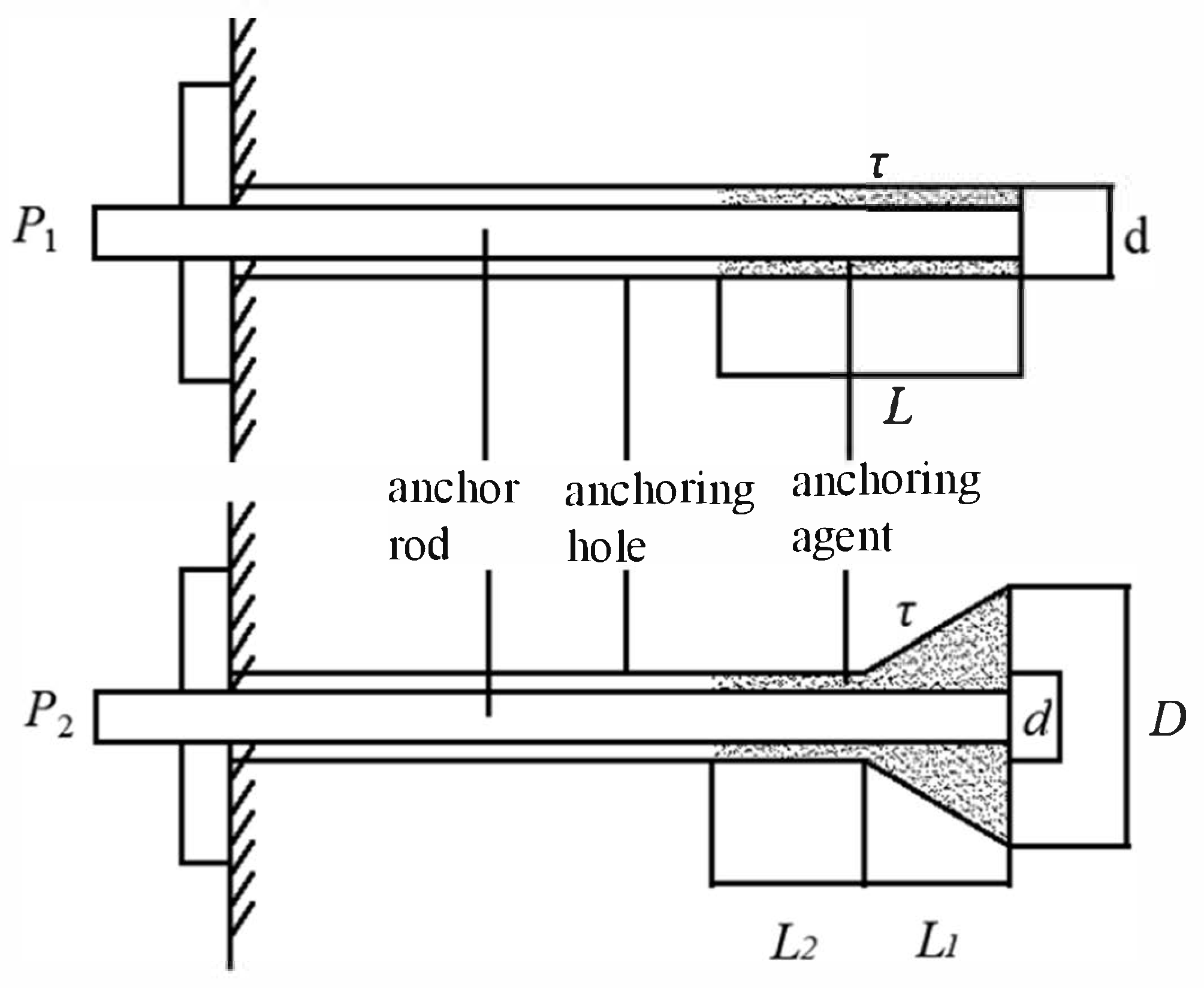
As illustrated in Figure 1, local reaming is performed at the bottom of the anchor hole to form an approximately inverted wedge-shaped reaming structure with a fixed angle and length. After anchoring, an enlarged end body is formed, which can effectively improve the bolt anchoring strength and enhance the tensile and pull-out resistance of the bolt compared with conventional anchoring.
Figure 1. Schematic of conventional anchoring and reaming anchoring.
Under the condition that the bolt anchoring length is identical, assuming that the bonding stress between the anchoring agent and the bolt is uniformly distributed along the anchoring length, the ultimate shear strength at the interface between the anchoring agent and the bolt is consistent. In this case, only the ultimate shear strength at the interface between the anchoring agent and the surrounding rock needs to be considered, with the bonding stress between the anchoring agent and the surrounding rock also assumed to be uniformly distributed along the anchoring length. Referring to the Technical Specification for Bolt Support in Coal Mine Roadways [26], the calculation formula for the pull-out force of a conventional bolt is:
P 1   =   π d τ L
where P1 is the pull-out force of the bolt in the conventional anchoring system, kN; d is the borehole diameter, m; τ is the ultimate bond strength at the surrounding rock-anchoring agent interface, MPa; and L is the anchoring length, m.
Similarly, the calculation formula for the bolt pull-out force after anchor hole reaming is derived as follows:
P 2   =   π τ [ ( D + d ) 2 l 1 2 + ( D 2 d 2 ) 2 + d l 2 ]
where P2 is the pull-out force of the bolt in the reaming anchoring system, kN; d is the borehole diameter, m; D is the reaming section diameter, m; τ is the ultimate bond strength at the surrounding rock-anchoring agent interface, MPa; l1 is the anchoring length of the reaming section, m; l2 is the anchoring length of the conventional section, m; and l1 + l2 = L.
As indicated by Equation (2), the pull-out force of the bolt after anchor hole reaming is significantly higher than that of conventional anchoring, and exhibits a positive correlation with the diameter and length of the reaming section.

2.2. Principle of High-Pressure Water Jet Rock Breaking

Scholars have analyzed and elaborated on the high-pressure water jet rock-breaking theory from various perspectives, proposing a series of classic theoretical hypotheses. Among these, the tensile-water wedge fracture theory posits that jet impact induces a continuous increase in water pressure within rock fractures, closely approaching the surface impact force of the jet; this water pressure penetrates into the fractures like a rigid wedge, promoting the propagation and coalescence of fractures. This theory explains the promotion of rock breaking by natural defects through the “water wedge effect” and is highly consistent with practical engineering phenomena.
In the rock breaking process, the impact force F of the high-pressure water jet on rock is expressed as:
F = ρ q v ( 1 c o s θ 0 )
where ρ is the jet density, kg/m3; q is the high-pressure water jet flow rate, m3/s, with q = vA (where A is the jet cross-sectional area, m2); v is the jet velocity, m/s; and θ0 is the jet angle (°).
The impact pressure P0 of the high-pressure water jet on rock is derived as:
P 0 = F / A = ρ v ( 1 c o s θ 0 )
As evident from Equation (4), the impact pressure of the jet on the rock increases as the jet impact angle increases. The threshold pressure for jet-induced rock breaking is approximately twice the shear strength of the rock, and the calculation formula for the water jet rock-breaking threshold pressure is given by [27]:
P c = P 0 [ 0.5 μ + 0.315 ( 1 + μ ) 3 / 2 ] 2 τ s ,
where Pc is the jet threshold pressure, MPa; τs is the rock shear strength, MPa; and μ is the rock Poisson’s ratio.

3. Determination of Key Nozzle Parameters

The Fluent module of the ANSYS (version:ANSYS 2024 r2) finite element analysis software was adopted to simulate and analyze the spray head with multiple nozzles. Based on the finite volume method, ANSYS-FLUENT outperforms the finite element method and finite difference method because its control equations abide by the conservation laws of momentum, mass and energy for any control volume.

3.1. Numerical Simulation Setup

In this study, the k-ε turbulence model was employed for the numerical simulation of the high-pressure water jet flow field. This model offers high accuracy for high-speed free jets and effectively captures the vortex structure and velocity attenuation characteristics of the jet. Mesh independence verification was conducted to ensure the reliability of simulation results, following the methodology proposed by Karpenko [28]. Three mesh schemes of 1 mm, 2 mm, and 3 mm were adopted for calculation. The 1 mm mesh was finally selected, as the variation in the maximum jet velocity was less than 3%, balancing both simulation accuracy and computational efficiency.
The boundary conditions and solution settings for the numerical simulation are as follows:
The nozzle inlet was set as a velocity inlet with a velocity of 30 m/s. This boundary condition was used only for the comparative optimization of nozzle structural parameters, including the number, spacing, and angle of nozzles. The uniform velocity inlet ensures a fair comparison of different nozzle schemes under the same inflow conditions, to accurately identify the optimal structural combination and avoid comparison deviations caused by different pressure boundaries.
The nozzle outlet was set as a pressure outlet with a gauge pressure of 0 MPa (atmospheric pressure). The gravitational acceleration of 9.8 m/s2 was applied along the z-axis. The convergence criteria were defined such that the residuals of the continuity, momentum, and energy equations were all below 10−5, and all flow field parameters tended to be stable. In addition, the second-order upwind scheme was used to discretize the governing equations to improve the accuracy of the calculation results.

3.2. Design of Numerical Simulation Scheme

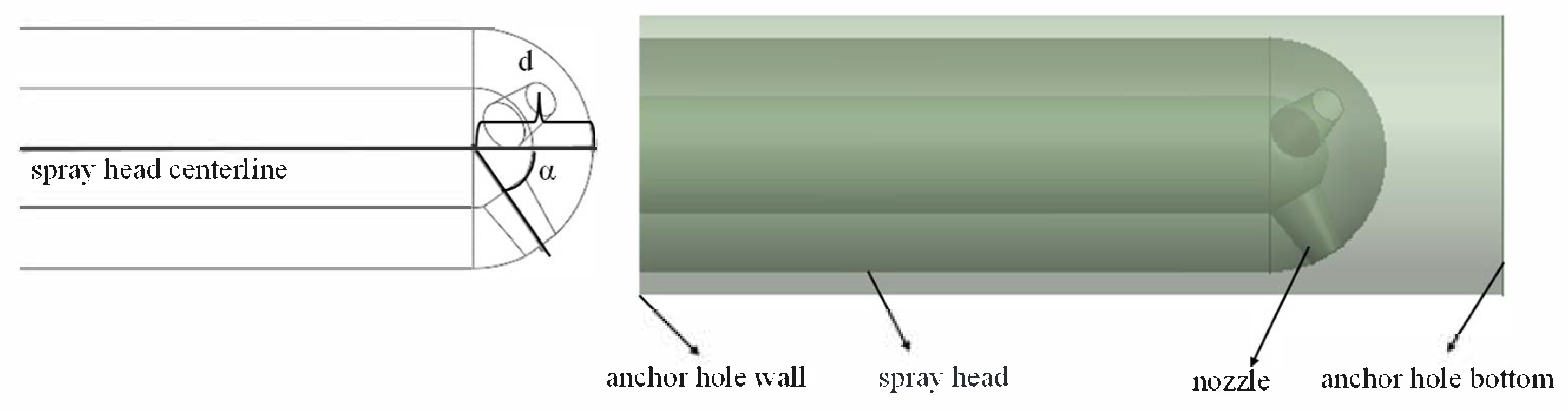
In accordance with the actual dimensions of coal mine anchor holes and on-site reaming operating conditions, the spray head was designed with a diameter of 2 cm and a length of 5 cm, with all nozzles directed forward (see Figure 2). To determine reasonable reaming spray head parameters and optimize the design scheme, numerical simulation was employed for preliminary investigation. Nozzle spacing is defined as the distance from the intersection of the nozzle axis and the main spray head axis to the top of the main spray head, while nozzle angle is defined as the included angle between the nozzle axis and the main spray head axis. The specific spray head design scheme is presented in Table 1.
Figure 2. Schematic diagram of the 3-nozzle model.
Table 1. Simulation design scheme of the jet nozzle.

3.3. Analysis of Simulation Results

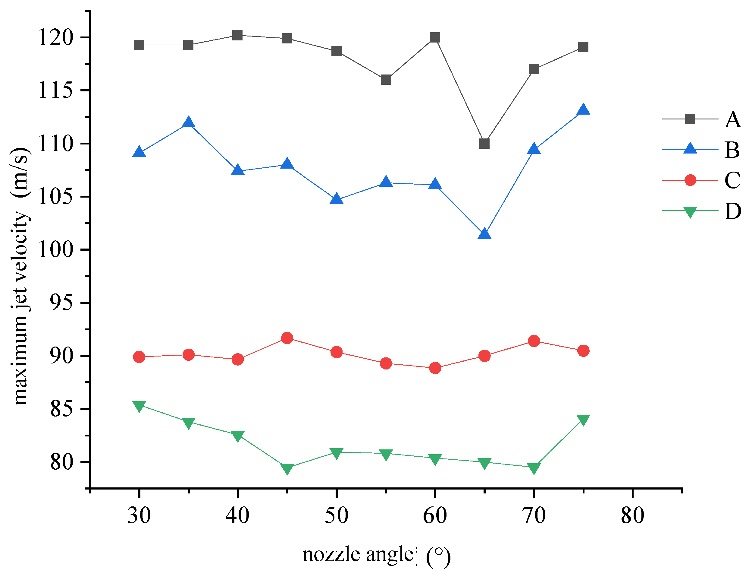
To facilitate the analysis of numerical simulation results, the maximum water jet velocity were statistically evaluated, with the results illustrated in Figure 3.
Figure 3. Maximum velocity of the high-pressure water jet.
As shown in Figure 3, the multi-nozzle spray head design effectively improves the water jet velocity, increasing the initial velocity of 30 m/s to a maximum of 120 m/s. Analysis of Figure 3 reveals the following trends: Group A—the maximum jet velocity maintains a generally high level, peaking at 120 m/s at a 60° nozzle angle, then slightly decreasing to 110 m/s at 65° before moderately rising thereafter; Group B—the maximum jet velocity fluctuates within the range of 105–110 m/s, dropping to 100 m/s at a 65° nozzle angle and then slightly recovering; Group C—the maximum jet velocity remains relatively stable, fluctuating around 90 m/s without a significant upward or downward trend; Group D—the maximum jet velocity varies between 80–85 m/s, with an overall low value. Additionally, the maximum jet velocity is relatively stable at a 10 mm nozzle spacing; at 15 mm, it decreases as the nozzle angle increases and slightly rises after 70°. A comparison of the results indicates that the 3-nozzle spray head design achieves a significantly higher jet velocity compared to the 4-nozzle counterpart, demonstrating that the 3-nozzle spray head provides greater reaming energy and facilitates the concentration of jet energy for reaming operations.
As illustrated in Figure 4, the maximum jet velocity reaches 120 m/s for the spray head designed with a 60° nozzle angle, featuring a relatively uniform jet velocity distribution. However, an increase in both nozzle spacing and the number of nozzles results in a decrease in jet velocity: the maximum velocity decreases by 14 m/s and 8 m/s when the nozzle spacing increases from 10 mm to 15 mm, and by 32 m/s and 26 m/s when the number of nozzles increases, respectively. As the nozzle spacing increases, the volume of liquid accumulating at the top of the spray head correspondingly increases; when the accumulated liquid volume reaches a certain threshold, it disturbs the liquid flow at the spray head inlet, thereby reducing the jet velocity.
Figure 4. Jet velocity cloud map of three nozzle models at a 60° angle.
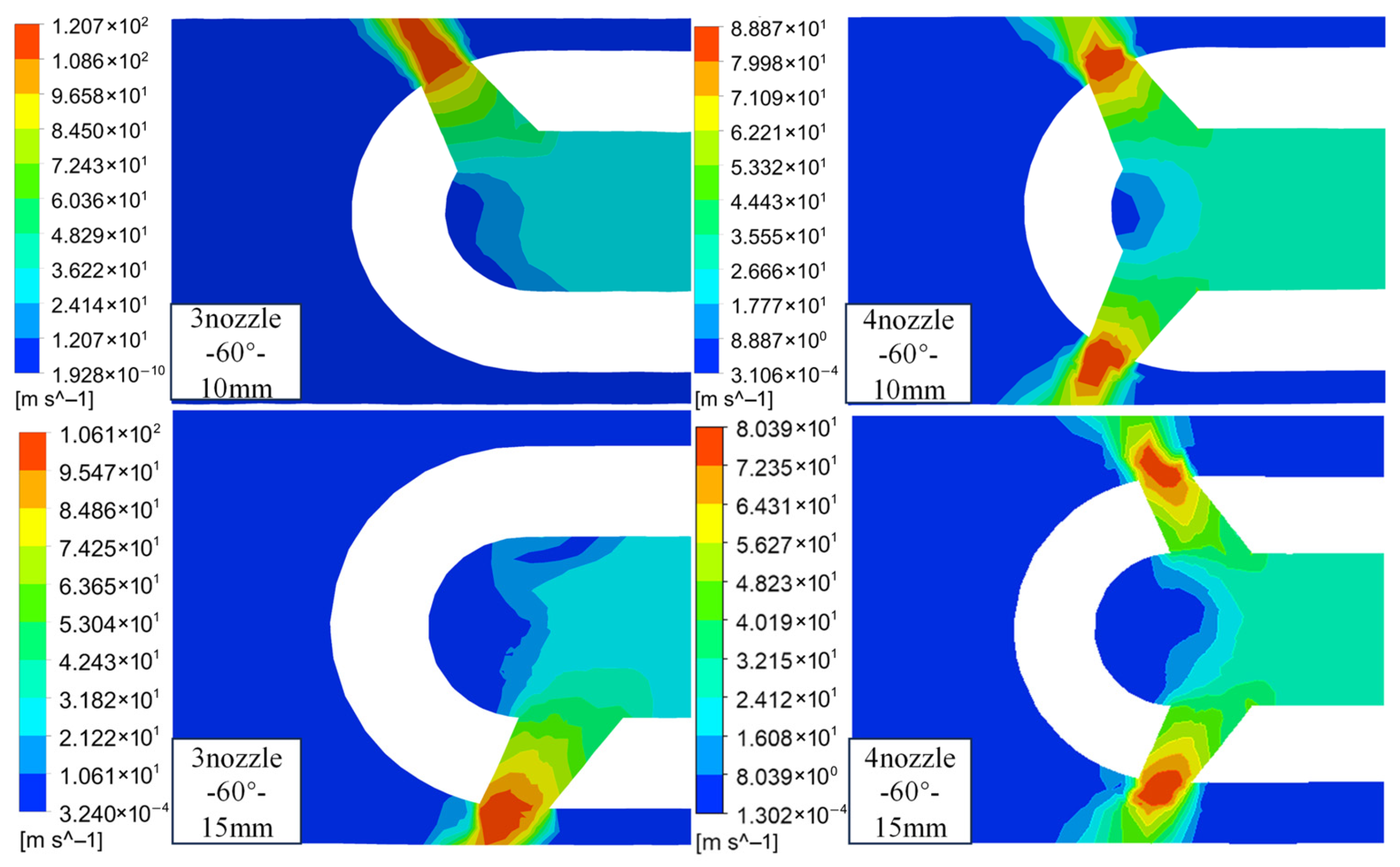
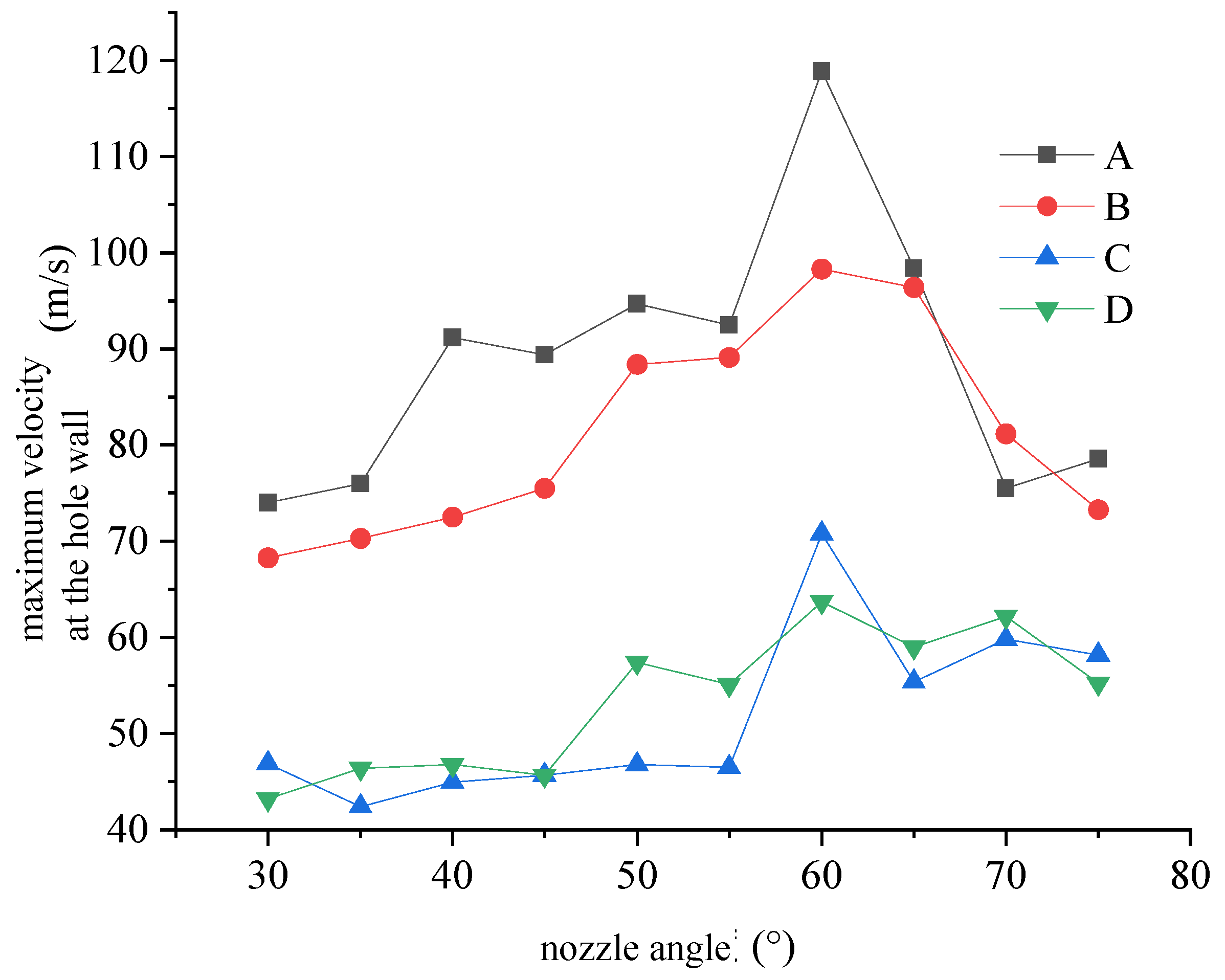
As shown in Figure 5, the maximum jet velocity impinging on the anchor hole wall were statistically evaluated. Within the nozzle angle range of 30–55°, the maximum jet velocity impinging on the anchor hole wall at a 15 mm nozzle spacing is higher than that at 10 mm. This is attributed to the increased nozzle spacing shortening the distance from the nozzle outlet to the hole wall, minimizing jet energy loss during propagation from the outlet to the wall. When the nozzle angle exceeds 60°, the jet velocity impinging on the anchor hole wall at a 10 mm spacing surpasses that at 15 mm, indicating that the influence of nozzle spacing on the jet impinging on the hole wall is weakened. Among all designs, the 3-nozzle spray head configuration achieves a significantly higher jet velocity on the anchor hole wall compared to the 4-nozzle configuration. For all spray head designs, the jet velocity impinging on the anchor hole wall reaches its peak at a 60° nozzle angle and tends to stabilize with a slight decrease thereafter.
Figure 5. Maximum jet velocity acting on the anchor hole wall under different schemes.
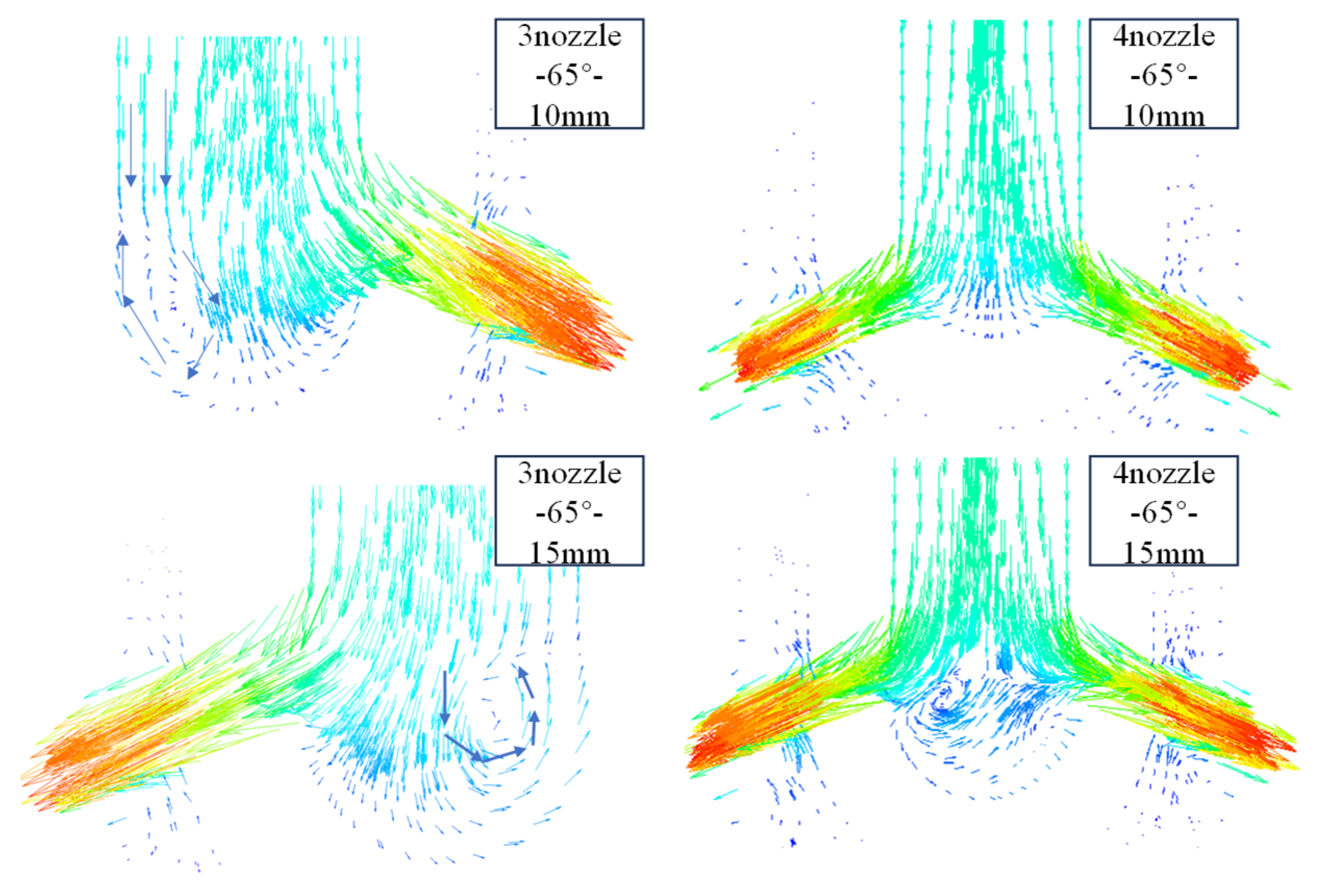
As observed in Figure 6, the maximum jet velocity decreases at a 65° nozzle angle for the 3-nozzle spray head, as its structural design impedes fluid flow, forming local vortices behind the nozzles and thereby reducing the jet velocity. In contrast, the 4-nozzle spray head structure exhibits no significant change in jet velocity at a 65° nozzle angle due to its symmetrical nozzle arrangement, which effectively prevents the generation of vortices that would otherwise affect the jet velocity. Combined with Figure 3, the significantly lower maximum jet velocity at a 15 mm nozzle spacing compared to 10 mm is due to the nozzles being farther from the top of the spray head, making them prone to vortex formation and other flow disturbances.
Figure 6. Jet velocity vector diagram of different nozzle arrangements at a 65° angle.
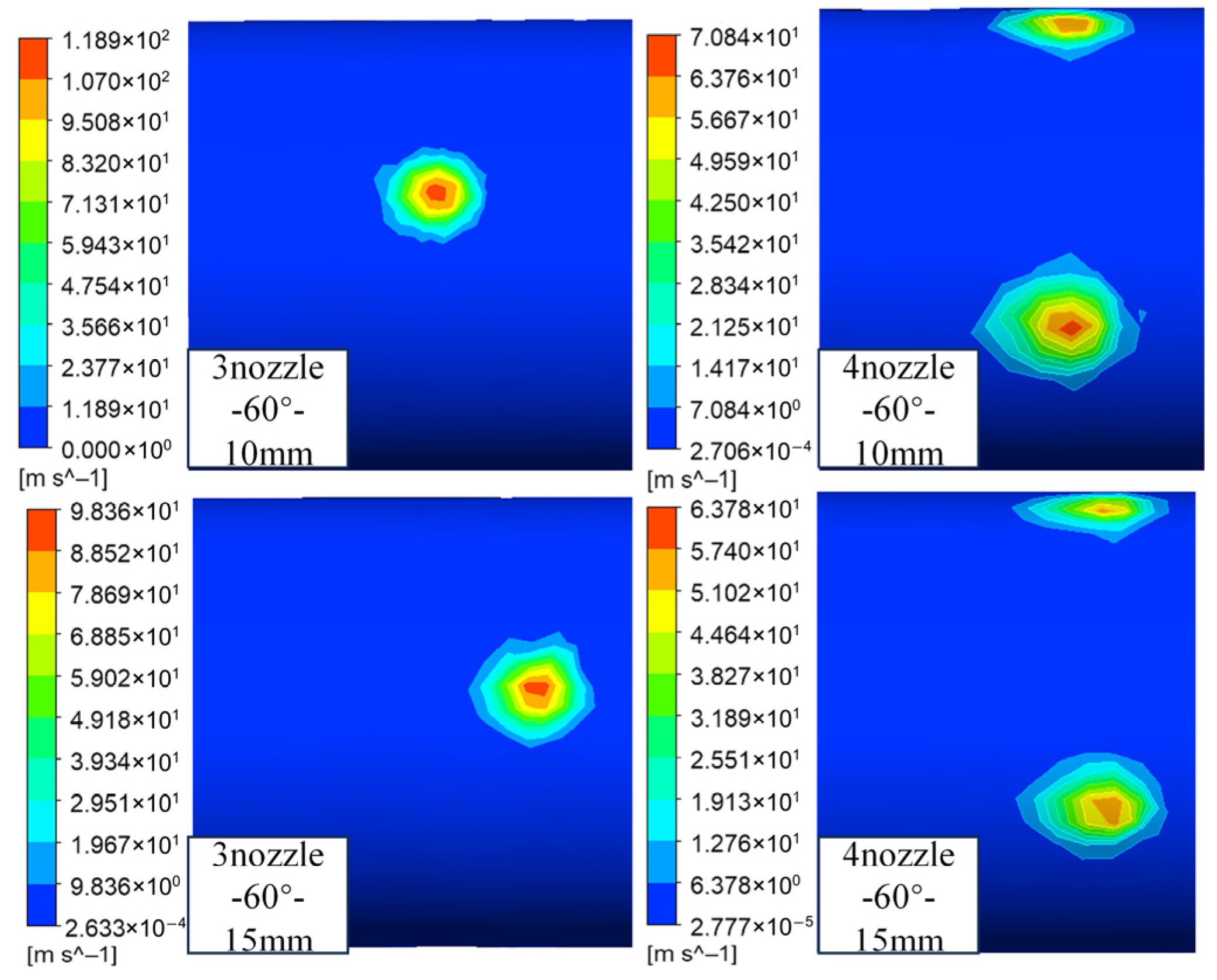
As shown in Figure 7, the jet velocity impinging on the anchor hole wall also decreases as the number of nozzles and nozzle spacing increase. The maximum wall velocity decreases by 20 m/s and 7 m/s when the nozzle spacing increases from 10 mm to 15 mm, and by 48 m/s and 35 m/s when the number of nozzles increases, respectively. Furthermore, the increased nozzle spacing causes a relative shift in the jet’s point of action on the hole wall, and this shift becomes more significant as the jet velocity increases.
Figure 7. Cloud map of jet velocity acting on the anchor hole wall at a nozzle angle of 60°.
A comprehensive analysis of the numerical simulation results for the spray head design indicates that the 3-nozzle spray head significantly outperforms the 4-nozzle counterpart in terms of both the maximum jet velocity and the maximum jet velocity impinging on the anchor hole wall, with the jet velocity peaking at a 60° nozzle angle. Considering the practical engineering requirements for reaming effectiveness and construction efficiency, the 3-nozzle spray head design was selected for subsequent laboratory experiments.

4. High-Pressure Water Jet Reaming Experiments

4.1. Preparation of Experimental Specimens and High-Pressure Water Jet Experimental System

(1)
Preparation of Experimental Specimens
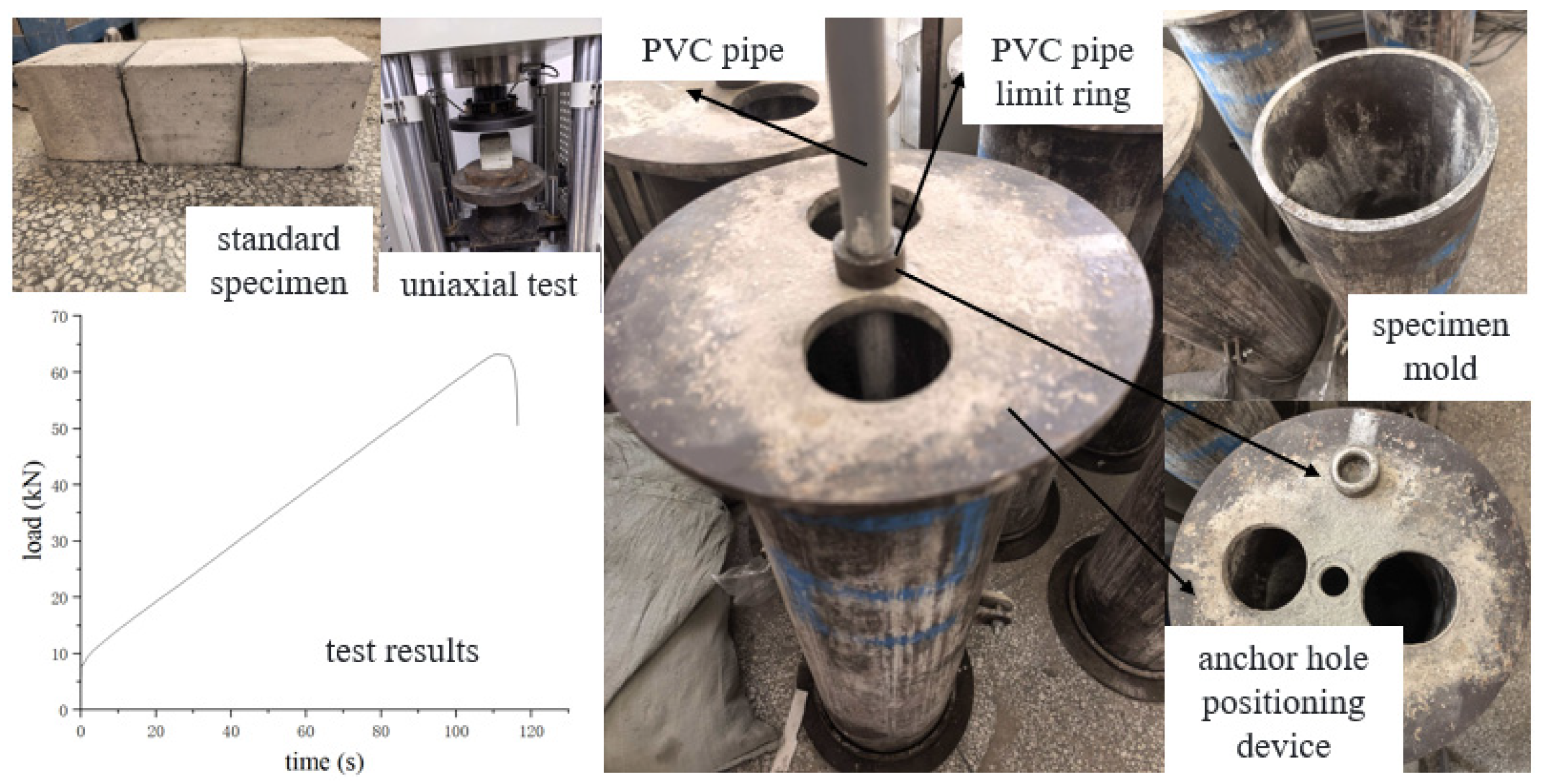
Rock masses with a uniaxial compressive strength of less than 30 MPa are generally defined as soft rocks. To simulate the actual operating conditions of high-pressure water jet reaming in soft rock, standard cubic specimens were prepared using similar materials with different proportions, and uniaxial compressive strength tests were conducted. Ultimately, the optimal proportion of similar materials was determined as sand: cement: gypsum: water = 65:20:10:15 (mass ratio). The average uniaxial compressive strength of standard specimens prepared with this proportion is 6.32 MPa, which satisfies the experimental requirements of this study.
The specimen mold was designed as a cylindrical mold with a diameter of 25 cm and a height of 50 cm, with an anchor hole positioning device installed at the center of the mold. During specimen preparation, a PVC pipe with a diameter of 30 mm was inserted into the center of the mold, and a 35 cm deep anchor hole was reserved in the specimen using the PVC pipe limit ring. The simulated materials were weighed according to the aforementioned proportion, thoroughly mixed, poured into the mold, and vibrated uniformly to ensure the quality of the soft rock-like specimens. The specimen mold is illustrated in Figure 8.
Figure 8. Similar material ratio test and specimen mold.
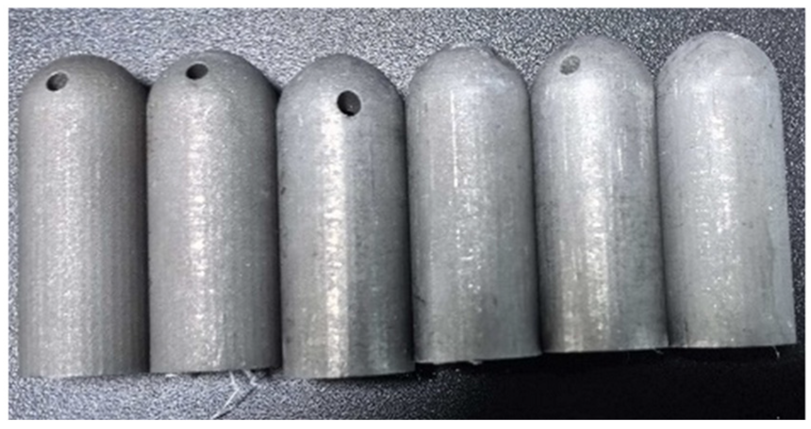
Based on the numerical simulation results, the 3-nozzle spray head design was adopted for laboratory tests. A full-scale (1:1) physical spray head prototype was manufactured via 3D printing to ensure consistency with the simulation model. The physical spray head prototype is shown in Figure 9.
Figure 9. 3D-printed spray head.
(2)
Construction of the High-Pressure Water Jet Experimental System
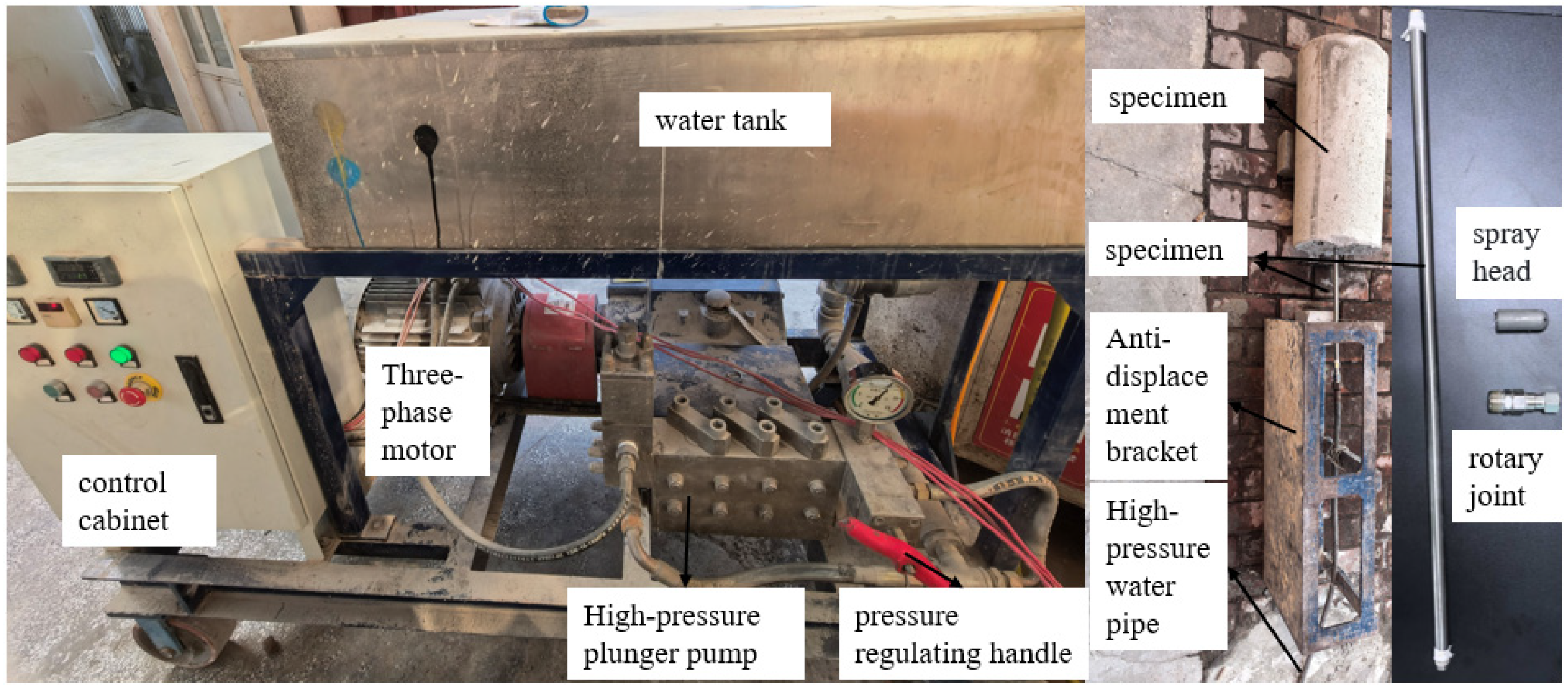
The composition of this experimental system is illustrated in Figure 10, which mainly includes a high-pressure plunger pump, a water tank, pressure and flow monitoring equipment, a test bench, a three-phase motor, a pressure regulating device, and various connecting pipeline joints. Its workflow is as follows: the motor is started via the control cabinet to drive the high-pressure plunger pump; the pressure handle is adjusted to increase pressure, and a high-pressure jet is formed through the high-pressure water pipe → rotary joint → stainless steel connecting pipe, which is ultimately ejected from the nozzle at a predetermined angle to impinge on the anchor hole wall. The rotary joint is capable of 360° rotation, connecting the jet impact points into a continuous surface to form annular reaming.
Figure 10. Composition of the high-pressure hydraulic reaming experimental system.

4.2. Analysis of the Anchor Hole Reaming Experimental Results

Since the stress state around the anchor hole is disturbed during drilling, the rock-breaking and reaming effect experiment was conducted under unconfined conditions. Cylindrical specimens with dimensions of Φ250 mm × 500 mm were prepared in accordance with the aforementioned mold specifications. The experimental reaming jet pressure was set to 20 MPa, the duration for a single reaming operation was two minutes, measured with a stopwatch; the spray head was inserted into the anchor hole, 5 cm away from the hole bottom. After reaming, high-definition observation equipment was used to acquire images of the anchor hole wall.
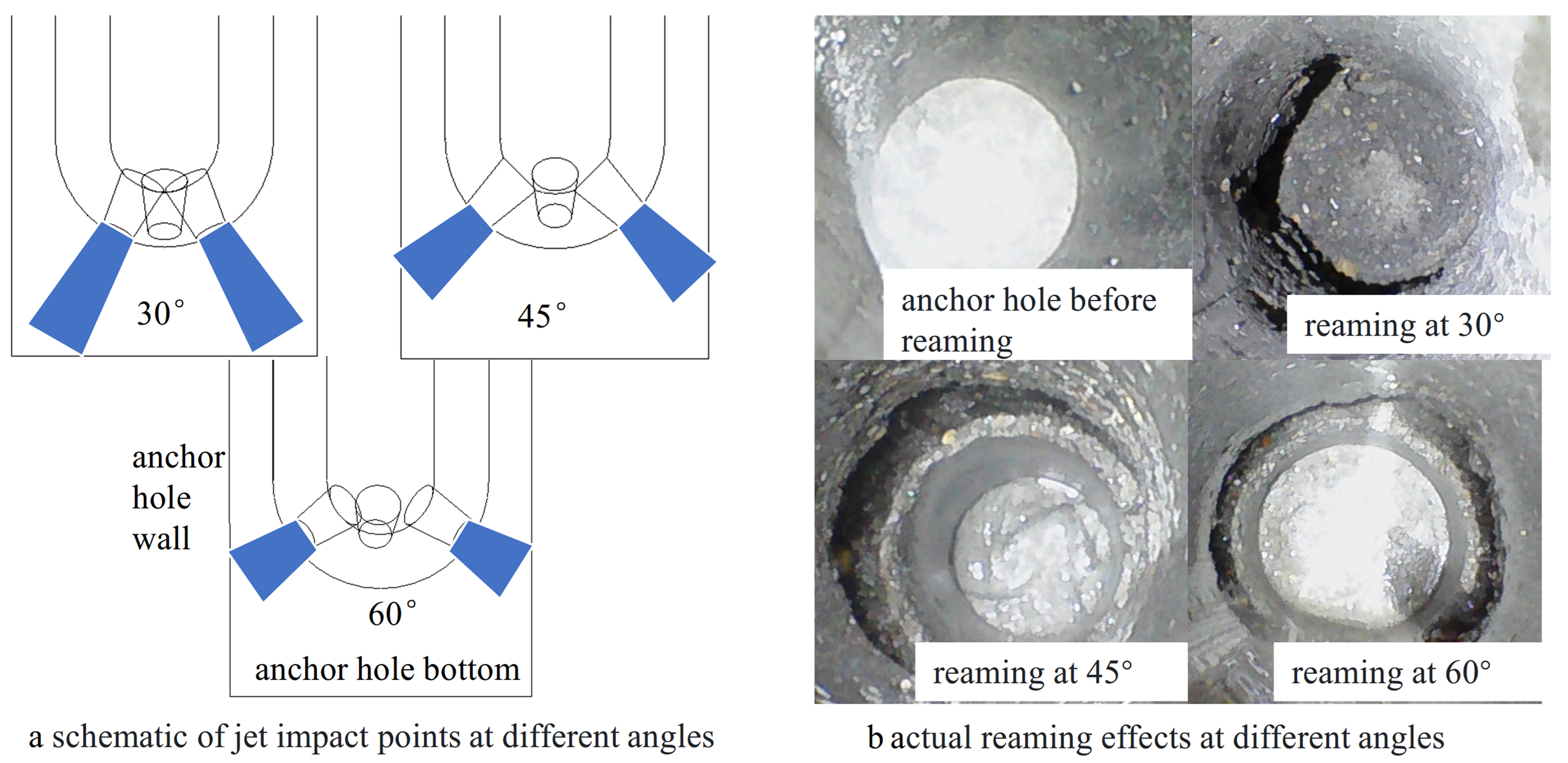
As shown in Figure 11, when the spray head has a 30° nozzle angle, the jet impinges on the junction of the anchor hole wall and the hole bottom. Under jet impact, the depth of the anchor hole further increases, resulting in an excessive bolt insertion length during anchoring; the exposed length of the bolt end does not meet the support requirements. In addition, the reaming effect at a 30° nozzle angle is weaker than that at 45° and 60°, while the latter two nozzle angles yield similar reaming effects, both achieving effective reaming.
Figure 11. Reaming effect of the high-pressure water jet under different nozzle angles.
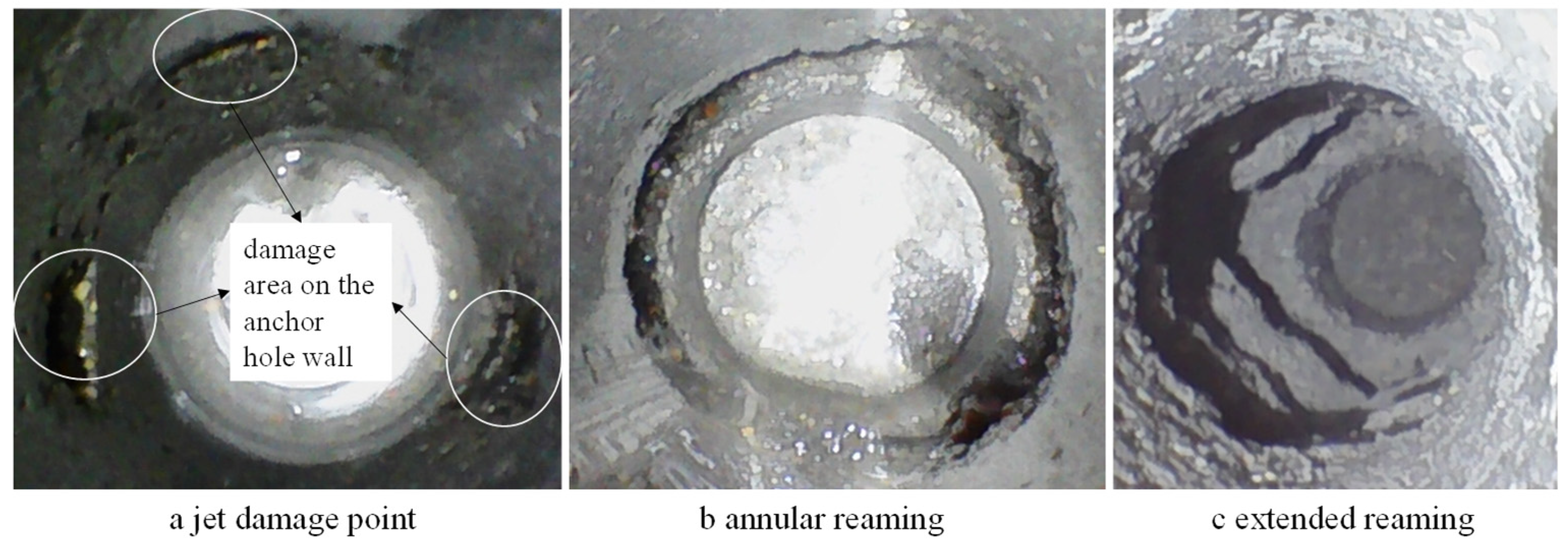
As illustrated in Figure 12, under high-pressure jet impact from the spray head’s nozzles, three discrete damage points initially appear on the anchor hole wall. Rotating the stainless-steel connecting pipe allows each nozzle’s jet to uniformly impact the hole wall, gradually expanding the damage points into an annular reaming with a consistent depth. Finally, by controlling the extension length of the spray head into the anchor hole and the reaming duration, the reaming section is gradually lengthened, forming an approximately inverted wedge-shaped structure with a deep inner part and a shallow outer part.
Figure 12. The three-stage reaming process of the high-pressure water jet for soft rock anchor holes.
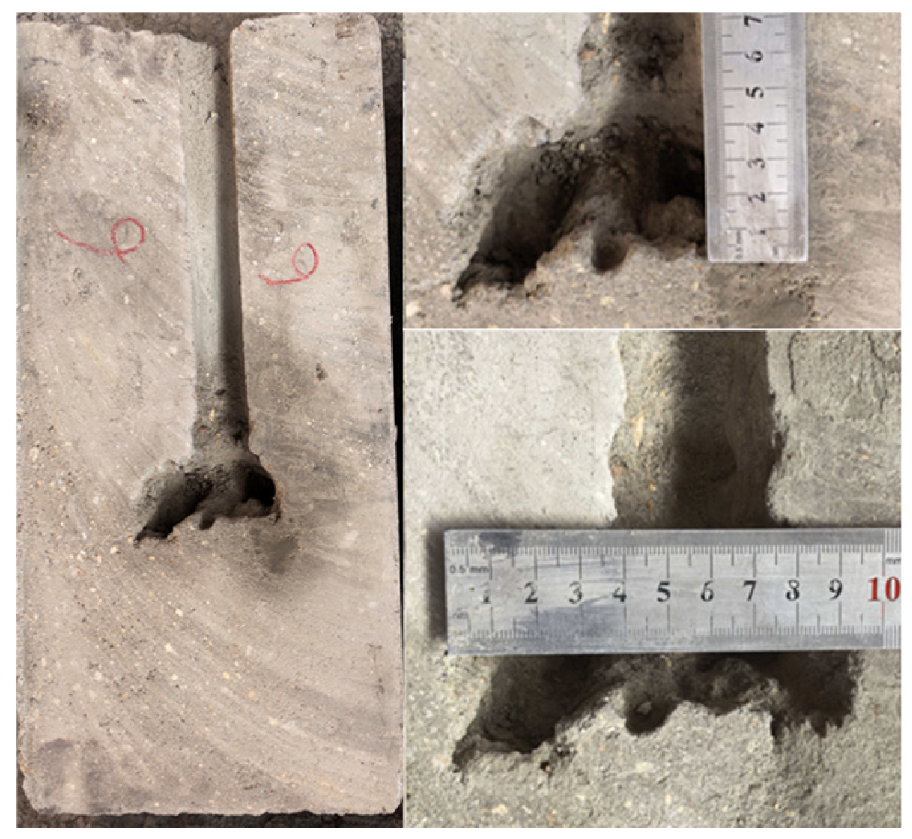
To intuitively observe the reaming effect, the reamed specimen was sectioned along its midline (as shown in Figure 13). It can be observed that the reaming shape is approximately wedge-shaped, and the angle is roughly consistent with the nozzle angle. For ease of comparison, the reaming effects of each experimental group are summarized in Table 2.
Figure 13. Reaming effect at a nozzle angle of 30° and spacing of 15 mm.
Table 2. Statistics of reaming effects of different nozzles.
As indicated in Table 2, under the same water pressure condition, the actual reaming effects of the nozzles with different parameters do not differ significantly, which is consistent with the numerical simulation results (the jet velocities at the nozzle outlet are comparable under the same initial conditions); among these, the nozzle with the parameter combination of 60–10 mm achieves the optimal reaming effect.
To verify the influence of high-pressure water jet reaming on the bolt anchoring effect, bolt pull-out experiments were conducted after reaming. Five groups (A, B, C, D, E) were established for the experiment, with three specimens per group. The specimens have dimensions of 250 mm in diameter and 500 mm in length, with an anchor hole depth of 350 mm; all specimens were reamed under 20 MPa water pressure for 2 min, adopting end anchoring with a bolt diameter of 25 mm and a length of 1 m. The parameter configuration for each group is as follows: Group A (reaming anchoring with a nozzle of 60° angle and 10 mm spacing), Group B (reaming anchoring with a nozzle of 60° angle and 15 mm spacing), Group C (reaming anchoring with a nozzle of 45° angle and 10 mm spacing), Group D (reaming anchoring with a nozzle of 30° angle and 10 mm spacing), Group E (conventional anchoring group without reaming). The results of the pull-out experiment are the average values of each group, with specific data presented in Table 3.
Table 3. Results of bolt pull-out experiments.
As shown in Table 3, among the five experimental groups, Group A exhibits the highest average pull-out load (51.99 kN), while Group E has the lowest (36.83 kN). The reasons are as follows: the anchor hole depth is identical for all specimens, so the anchoring length of the grouted bolts is consistent; the bolt failure mode in weak surrounding rock is primarily slip failure at the interface between the anchoring agent (backfill) and the surrounding rock, thus the bolt pull-out force is mainly influenced by the length and depth of the reaming section. The nozzle in Group A achieves the optimal reaming effect (with both reaming depth and length superior to those of the other groups), resulting in the highest pull-out force; Group E is not reamed, so the contact area between the anchoring agent and the surrounding rock is the smallest, leading to a lower pull-out force compared to the other reamed groups. The experimental results confirm that anchor hole reaming can effectively improve the bolt anchoring strength.

5. Discussion

Aiming at the engineering problems including borehole collapse, drill jamming, and tool arm fracture that frequently occur in mechanical reaming devices during anchor hole reaming and anchoring in broken and weak coal mine surrounding rock, existing high-pressure water jet nozzles are unsuitable for anchor hole reaming. This study introduces high-pressure water jet technology into anchor hole reaming and proposes a non-contact reaming technical solution. The designed multi-nozzle structure avoids direct contact between rigid cutting tools and surrounding rock, significantly reduces equipment failure rate, minimizes rock mass disturbance, and maintains rock mass integrity, providing a new technical approach for safe and efficient reaming in soft rock tunnels.
Verified by FLUENT numerical simulations and laboratory tests, the parameter combination of 60° nozzle inclination, three nozzles, and 10 mm spacing achieves the optimal reaming performance. The results quantitatively improve jet velocity and anchoring performance, enrich the design theory of non-mechanical reaming, and provide key parameters and theoretical support for equipment development and system upgrading.
High-pressure water jet reaming can effectively replace traditional mechanical reaming, with outstanding advantages in soft rock adaptability, reaming efficiency, and construction disturbance control. It is suitable for anchoring support under complex geological conditions and shows broad engineering application prospects. Given the scale differences between laboratory and field conditions, on-site verification will be further conducted considering real conditions such as high ground stress and fractures. The reaming time in the experiment was 2 min, which will be further reduced in the future. With the gradual promotion of bolt reaming support, quantitative changes will eventually lead to qualitative improvement, forming a complete technical system to provide more reliable support for surrounding rock control in complex soft rock tunnels in deep mines.

6. Conclusions

(1)
To solve the problems of hole collapse, tool jamming, and cutter arm fracture of mechanical reaming devices in the anchoring support of anchor holes in weak and fractured surrounding rock of coal mines, a multi-nozzle reaming nozzle for anchor holes was designed based on the rock-breaking principle of high-pressure water jets, which enables efficient and environment-friendly reaming operations.
(2)
The Fluent fluid simulation software was used to study the influence of key nozzle parameters on the high-pressure jet, and the relationships between the number of nozzles, nozzle spacing, nozzle angle, and jet velocity were clarified: when the nozzle angle is 60°, the rock-breaking jet velocity is maximized, and the rock-breaking energy is the highest; the jet velocity of the 3-nozzle design is significantly higher than that of the 4-nozzle design; when the nozzle spacing is the same, the maximum jet velocity varies slightly with different angles; the maximum jet velocity at a nozzle spacing of 10 mm is greater than that at 15 mm. Finally, the optimal parameter combination of the reaming nozzle was determined as: 3 nozzles, nozzle angle of 45°~60°, and nozzle spacing of 10 mm.
(3)
A high-pressure water jet reaming system was independently developed, the reaming nozzle was manufactured using 3D printing technology, and simulated specimens with a uniaxial compressive strength of 6.32 MPa were prepared using similar materials to carry out laboratory reaming tests and bolt pull-out experiments. The results show that under a jet pressure of 20 MPa, the nozzles with 45° and 60° angles exhibit excellent reaming performance; compared with the unreamed bolt (anchoring force of 36.83 kN), the bolt anchoring force can reach 51.99 kN after reaming with the nozzle featuring a 60° angle and 10 mm spacing, and the anchoring strength is enhanced by 41.16%.

Author Contributions

Methodology, H.N.; Software, A.L.; Validation, Y.S.; Writing–original draft, A.L.; Writing–review & editing, A.L.; Project administration, H.N.; Funding acquisition, H.N. All authors have read and agreed to the published version of the manuscript.

Funding

This research was funded by National Natural Science Foundation of China grant number 51974106. The APC was funded by National Natural Science Foundation of China.

Institutional Review Board Statement

Not applicable.

Data Availability Statement

The original data presented in this study are available from the corresponding author on reasonable request.

Conflicts of Interest

The authors declare no conflicts of interest.

References

  1. Kang, H.P. Seventy years development and prospects of strata control technologies for coal mine roadways in China. J. Chin. Rock Mech. Eng. 2021, 40, 1–30. [Google Scholar] [CrossRef]
  2. Kang, H.P.; Yi, K. Simulation study on dilatant and rheologic properties of soft rocks surrounding deep roadway and its application. J. China Coal Soc. 2023, 48, 15–33. [Google Scholar] [CrossRef]
  3. Shan, R.L.; Peng, Y.H.; Kong, X.S.; Xiao, Y.H.; Yuan, H.H.; Huang, B.; Zheng, Y. Research progress of coal roadway support technology at home and abroad. Chin. J. Rock Mech. Eng. 2019, 38, 2377–2403. [Google Scholar] [CrossRef]
  4. Yang, X.J.; Lou, H.P.; Cui, N.; Guo, D.; Xiao, L.L.; Jiao, Y.P.; Zou, Z.J. Study on large deformation mechanism and support of soft rock roadway. J. Coal Sci. Technol. 2015, 43, 1–6. [Google Scholar] [CrossRef]
  5. Pinazzi, P.C.; Spearing, A.J.S.; Jessu, K.V.; Singh, P.; Hawker, R. Mechanical performance of rock bolts under combined load conditions. Int. J. Min. Sci. Technol. 2020, 30, 167–177. [Google Scholar] [CrossRef] [Scilit]
  6. Blanco, M.L.; Tiiani, M.; Hadj-Hassen, F.; Noiret, A. Assessment of the bolt-grout interface behaviour of fully grouted rock bolts from laboratory experiments under axial loads. Int. J. Rock Mech. Min. Sci. 2013, 63, 50–61. [Google Scholar] [CrossRef] [Scilit]
  7. Liu, S.; He, D.; Jia, H.; Fu, M.; Hou, B. Anchoring eccentricity features and rectifying devices for resin grouted bolt/cable bolt. Int. J. Min. Sci. Technol. 2022, 32, 1059–1073. [Google Scholar] [CrossRef] [Scilit]
  8. Pang, J.; Yao, W. Local weak-supporting mechanism and rational support form in soft rock tunnel. J. Min. Saf. Eng. 2017, 34, 754–759. [Google Scholar] [CrossRef]
  9. Cheng, L.; Zhang, H.; Jiang, P.; Cai, R.; Li, B. Mechanical properties and experimental study on reaming anchor in soft coal and rock mass. J. Min. Saf. Eng. 2019, 36, 1153–1160. [Google Scholar] [CrossRef]
  10. Liu, S.; Shang, P.; Zhang, H.; Jiang, Y. Reaming mechanism of bolt hole in entry within weak surrounding rock and experimental research. J. China Coal Soc. 2015, 40, 1753–1760. [Google Scholar] [CrossRef]
  11. Zhang, H.; Cheng, L. Experimental study on anchorage performance by reaming in bottom of bolt hole for soft coal seam. J. Saf. Sci. Technol. 2015, 11, 28–32. [Google Scholar]
  12. Zhang, H.; Cheng, L. Study on anchoring mechanism and anchoring performances of bottom reaming for anchoring borehole in soft seam. Coal Sci. Technol. 2016, 44, 18–21. [Google Scholar] [CrossRef]
  13. Zhang, W.; Chen, Q.; Liu, S.; Wang, P.; Shi, J. Study on bottom enlarged anchoring mode and reaming parameters of bolt boreholes in mine soft rock roadway. Coal Sci. Technol. 2017, 45, 53–58. [Google Scholar] [CrossRef]
  14. He, D.; Liu, S.; Fu, M.; Jia, H.; Zhang, W.; Song, W. Anchoring effect guarantee method and experiment for the bottom reaming area of borehole in weak surrounding rock of coal mine roadway. J. China Coal Soc. 2024, 49, 108–120. [Google Scholar] [CrossRef]
  15. Liu, S.; Zhang, R.; Hou, J.; Yao, B.; Fu, M.; He, D. Research on mechanism and parameters of reaming anchorage for grouted anchor cable in roadway floor. J. Min. Saf. Eng. 2025, 7, 37–50. [Google Scholar] [CrossRef]
  16. Wang, Z.; Yin, Y.; Zhao, T.; Ma, J.; Wu, W. Numerical simulation study on bolting mechanism and support control of soft rock roadway. J. Shandong Univ. Sci. Technol. 2021, 40, 35–43. [Google Scholar] [CrossRef]
  17. Wang, S.; Nan, H.; Qiao, J.; Wang, Z. Experimental Study on Resin Anchoring with Reaming Bottom and Filling in Soft Rock. ACS Omega 2023, 8, 8815–8826. [Google Scholar] [CrossRef] [Scilit]
  18. Nan, H.; Wang, S.; Wang, J.; Luo, M. Experimental study on preventing slippage failure of resin bolt in coal roadway by backfilling with enlarged bottom. Saf. Coal Mines 2021, 52, 54–62. [Google Scholar] [CrossRef]
  19. Jia, H.; Wang, Y.; Liu, S.; Li, Y.; Shao, R.; Wang, G.; Guo, Z.; Wang, L. Experimental study on double cuneiform reamed anchorages for cable bolt boreholes in soft rock. Int. J. Rock Mech. Min. Sci. 2022, 158, 105198. [Google Scholar] [CrossRef] [Scilit]
  20. Liu, S.; Song, Q.; Zhang, H.; Jiang, Y.; Xu, X.; Yao, B.; He, X.; Fan, K.; Xu, L. A Single Wing Drilling Device for Anchoring Hole Bottom. Chinese Patent CN204024476U, 17 December 2014. [Google Scholar]
  21. Nan, H.; Song, M.; Kong, S. Mining Anchor Bolt Hole Internal Reamer. Chinese Patent CN106968604B, 23 November 2018. [Google Scholar]
  22. Skrzypkowski, K. Evaluation of rock bolt support for Polish hard rock mines. E3S Web Conf. 2018, 35, 01006. [Google Scholar] [CrossRef] [Scilit]
  23. Kishor, S.; Shrestha, P.P.; Dinesh, B.; Yfantis, E.A. Hard-Hat Detection for Construction Safety Visualization. J. Constr. Eng. 2015, 2015, 721380. [Google Scholar] [CrossRef] [Scilit]
  24. Ba, Q.; Liu, Y.; He, L.; Shen, K.; Xiong, W.; Zhao, X. Experimental study of key parameters and hole forming effect of hydraulic jet external rotary drilling nozzle. J. China Univ. Min. Technol. 2021, 50, 1087–1095. [Google Scholar] [CrossRef]
  25. Zhou, L.; Li, L.; Xia, B.; Yu, B. Fracture pattern and influencing factors of guided hydraulic fracturing with radial slot and well borehole. J. China Coal Soc. 2022, 47, 1559–1570. [Google Scholar] [CrossRef]
  26. GB/T 35056-2018; China Coal Industry Association Technical Specification for Anchor Rod Support in Coal Mine Roadways. China Standard Press: Beijing, China, 2018.
  27. Shen, Z. Water Jet Theory and Technology; China University of Petroleum Press: Dongying, China, 1998; pp. 281–290. [Google Scholar]
  28. Karpenko, M. Aircraft Hydraulic Drive Energy Losses and Operation Delay Associated with the Pipeline and Fitting Connections. Aviation 2024, 28, 1–8. [Google Scholar] [CrossRef] [Scilit]
Disclaimer/Publisher’s Note: The statements, opinions and data contained in all publications are solely those of the individual author(s) and contributor(s) and not of MDPI and/or the editor(s). MDPI and/or the editor(s) disclaim responsibility for any injury to people or property resulting from any ideas, methods, instructions or products referred to in the content.

Article Metrics

Citations

Article Access Statistics

Multiple requests from the same IP address are counted as one view.