Article

3D Printing and Characterization of HA/Mg-Reinforced PLA–PHA–PHB Composite Scaffolds for Biomedical Applications

by
Motahareh Sadat Raziyan
1,
Giedrius Janusas
1,*,
Wojciech Grodzki
2,
Ewa Borucińska-Parfieniuk
2,
Sigita Urbaite
1 and
Dariusz M. Perkowski
2
1
Faculty of Mechanical Engineering and Design, Kaunas University of Technology, Studentų 56, 51424 Kaunas, Lithuania
2
Faculty of Mechanical Engineering, Bialystok University of Technology, Wiejska 45C, 15-351 Bialystok, Poland
*
Author to whom correspondence should be addressed.
Appl. Sci. 2026, 16(8), 3647; https://doi.org/10.3390/app16083647
Submission received: 9 March 2026 / Revised: 30 March 2026 / Accepted: 4 April 2026 / Published: 8 April 2026
(This article belongs to the Special Issue Nonlinear Dynamics in Mechanical Engineering and Thermal Engineering)

Abstract

This research introduces a new hydroxyapatite-based composite, designed as a bone-implant scaffold—easy, quick, economical, and closely mimicking the structure of natural bone. Additive manufacture was used to print bioactive material to form a scaffold structure. Thus, during the experimental research, three different composite materials were made to examine both their mechanical and morphological properties. Numerical modeling was used to maximize and prove the mechanical and biological performance of the HA-polymer grafts. The obtained results indicated that incorporating HA and Mg particles into a polymeric matrix allows the structure to be used in tissue engineering. Best results were obtained using a structure, designed from PLA and PHA at 30%, PHB at 25%, Mg at 5%, and HA at 10%. The composite was distinguished by its lightness, strength, and biocompatibility, making it suitable for tissue engineering.

1. Introduction

Recently, bone-tissue engineering has emerged as an effective solution for the treatment of bone abnormalities by introducing scaffolds that support cell growth, promote blood flow, and facilitate tissue regeneration. This innovative approach uses biocompatible scaffolds—often made from hydrogels, ceramics, or polymers—that provide a three-dimensional structure to support cell attachment and proliferation. These scaffolds not only serve as a physical foundation for new tissue but also promote angiogenesis, or the formation of new blood vessels, which is crucial for delivering nutrients and oxygen to the regenerating tissue. By supporting these biological processes, bone-tissue engineering promotes efficient tissue regeneration, ultimately improving patient outcomes and enhancing the body’s natural healing capacity.
The performance of the designed scaffold’s bone structure depends largely on the ability to control parameters such as resistance to external loading, porosity, and pore size, which promote cell infiltration, vascularization, nutrient and oxygen flow. Thus, pore geometry directly influences the mechanical behavior of the scaffolds, their structural stability, and permeability. Porosity is also important for providing food to cells. Moreover, today scaffolds are studied not only as structural supports but also as active structures capable of bone regeneration and cellular production [1,2,3]. Such structures closely mimic the function of bone tissue, providing mechanical support while also facilitating cell attachment, proliferation, and the regeneration of new bone. The concept of an ideal scaffold should include an intricate system of pores that allows cells to migrate and attach to the structure and channels that facilitate the delivery of oxygen and nutrients to the cells. The structure itself should be shaped according to specific requirements based on the patient’s anatomy and have enough resistance to support tissue under load. In addition, the biocompatibility ensures that the cells can interact with the surrounding tissue.
In this research paper, only biologically compatible and natural components were used for the fabrication of scaffolds. Hydroxyapatite (HA)—a key natural component that, if used alone, mainly contributes its calcium-related properties, but when combined with polymers in composite materials, it can provide both mechanical support and bioactivity. Usually, HA is incorporated into different polymer matrices to improve osteoconductivity and bioactivity, making the scaffolds more suitable for bone regeneration, alongside biocompatible polymers that offer ease of processing, flexibility, and biodegradability [4,5,6,7,8]. Therefore, the right combination and proportion of biodegradable polymers such as polylactic acid (PLA), polyhydroxyalkanoate (PHA), and poly(3-hydroxybutyrate) (PHB) with HA may result in the formation of a natural bone-like composite that promotes cell proliferation and adhesion in tissue engineering applications [9]. Biopolymer PLA is preferred due to its mechanical strength and low cost, PHB because of its ability to create an environment for tissue growth and cell repair, and PHA due to its biodegradability and high compatibility [1,9,10]. The integrity of a composite material depends largely on the uniform dispersion of its constituent components. Thus, the primary objective in developing such composites was to obtain materials with improved performance by enhancing the key properties of the individual components. Mechanical strength, biodegradability, the ability to build and support cell replication, and other positive aspects sought by scientists in this field were achieved mainly through dispersion of components, control of proportions, and crystallinity [11,12,13]. The effectiveness of these scaffolds increases with particle functionalization. For example, magnesium hydroxide accelerates PLA degradation and creates a suitable environment for cells [14,15].
Polymer Matrix Composites (PMCs) are extensively utilized due to their excellent mechanical properties and ease of fabrication. They are known for their high strength, stiffness, corrosion resistance, and design flexibility. Zhang et al. [16] conducted extensive research on PLA/HA composites due to their bioactivity and mechanical properties. The outcome of this NHA modification demonstrated improved hydrophilicity and reduced micropores. As NHA content increased, compressive strength increased, surpassing that of HA ceramics. Designed NHA scaffolds were excellent candidates for enhanced bone bioactivity and bone regeneration. Ansari et al. 2017 [17] a porous composite scaffold made of medium-chain-length poly(3-hydroxyalkanoates) (mcl-PHA) and hydroxyapatite (HA) using the particulate leaching technique with NaCl as a porogen. The strategy showed enhanced PHA accumulation and monomer composition control, improved crystallinity, and confirmed successful composite formation. Bhattacharjee. et al. [18] developed 3D composites with hydroxyapatite (HA) and zinc-functionalized starch composites to create a mechanically strong and biologically stable bone substitute. The paper highlighted the role of nanostructures as a biological enhancer in HA-based grafts for biocompatible and cost-effective bone construction. Urrutia et al. [19] created a 3D porous T/HA composite using robocasting (an extrusion-based additive manufacturing technique) and then injected it with an injectable α-tricalcium phosphate (α-TCP) foam. It met clinical requirements for mechanical strength, porosity, and anatomical compatibility.
However, one of the main issues in designing novel composite materials for tissue engineering is the complexity and challenges in achieving high reproducibility during the fabrication of scaffolds. Researchers typically use techniques such as porogen leaching, electrospinning, freeze-drying, phase separation, and additive manufacturing. In this research, 3D printing was used to fabricate the scaffold to the desired shape and size, ensuring appropriate porosity and architecture, and enabling it to function for a certain period under load-bearing conditions. The designed scaffold was made from polymer PLA, PHA, and PHB, and combined with calcium and magnesium. Here, active ceramic components were used to imitate the structure of natural bone and vary the properties of composites. Thus, mechanical properties were examined through compression testing, complemented by numerical analysis performed with ANSYS 2026 R1 software to evaluate and compare theoretical and experimental results. Surface morphology was examined using Scanning Electron Microscopy (SEM), and chemical composition was analyzed with X-ray Diffraction (XRD) and X-ray test. Thus, different experimental techniques provided valuable insights into porosity, crystallinity, dispersion, and related structural parameters. Results showed that the integration of the HA and Mg into the polymer matrix may boost mechanical strength, improve surface morphology, and facilitate proper integration into the bones. Experimental results provided useful information on porosity, crystallinity, dispersion, and other related parameters.

2. Materials and Methods

2.1. Materials Synthesis

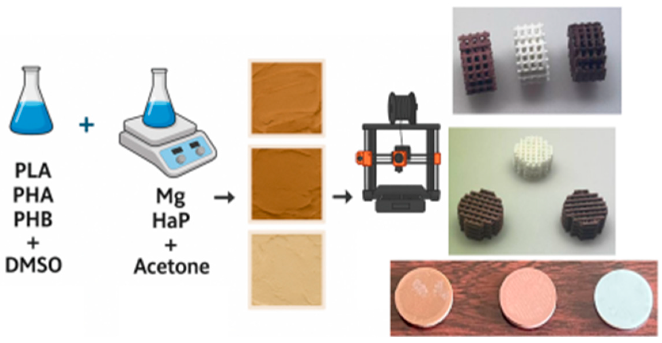
In this research, biodegradable polymers (PLA, PHA, PHB) were dissolved in DMSO (see Figure 1), then mixed with an inorganic phase (Mg and HA) in the presence of acetone to obtain homogeneous composite pastes with varying filler content. Different concentrations of polylactic acid (PLA), Polyhydroxyalkanoates (PHA), Poly(3-hydroxybutyrate) (PHB), and HA were used in the experimentation to form composite materials suitable for scaffolding, and only the three best compositions were selected for this research (Table 1). Firstly, hydroxyapatite was prepared from cow bones, cleaned, sterilized, and then synthesized using calcination, obtaining HA particles of size ranging from 500 to 800 nm [20].
Furthermore, polymer pellets were dissolved in DMSO and sonicated for 1 h, while HA and Mg were dispersed in acetone and sonicated for 2 h. The polymers and HA were mixed at varying weight percentages using high-shear mixing at 2000 rpm for 10 min, followed by extrusion through a twin-screw extruder (Noztek, Shoreham-bySea, West Sussex, UK) at 200 °C and 100 rpm to form the filaments. Paste-like material was prepared by hand, crushed into pellets, and extruded into filaments for 3D printing using the FDM method to produce scaffolds and samples for mechanical testing (Figure 1).
Mg content was kept constant at 5 wt. % in all samples, while HA content and polymer composition were varied in ratios, in order to evaluate their influence on the properties of the samples (Table 1). Magnesium powder, polylactic acid (PLA), Polyhydroxyalkanoates (PHA), Poly(3-hydroxybutyrate) (PHB) pellets, DMSO, and acetone were all from Sigma Aldrich (St. Louis, MO, USA). Variations in color and structure were evident depending on the polymer composition and HA content.

2.2. Scaffolds Design

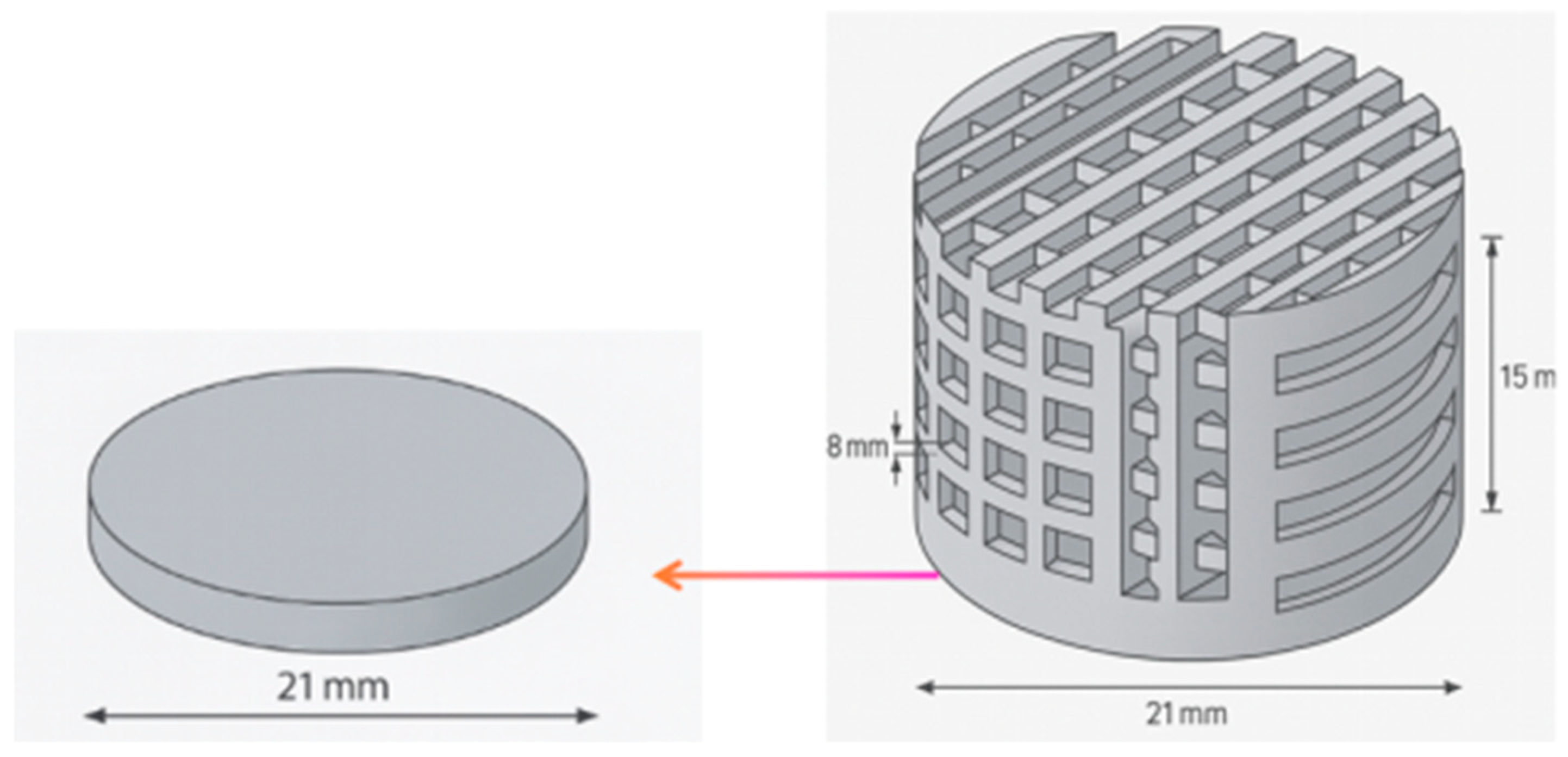
Using SolidWorks v. Student Premium, a porous cylindrical scaffold design was created for further investigations (Figure 2). Three different composite structure filaments were then used for 3D printing of scaffolds on a Prusa printer, using a nozzle size of 0.3 mm, a layer height of 0.1 mm, and an interlayer spacing of 0.25 mm. The bed temperature was maintained at 50 °C, while the nozzle operated at 180 °C.
The composites were cut into small pieces and extruded into filaments for scaffold fabrication. The scaffolds were printed using a layer-by-layer deposition approach, with optimized print speed, temperature, and layer thickness. After printing, the disc was cut for testing, where no porosity was needed, providing a 15 mm disc initially to facilitate easier printing.

2.3. Characterization of Scaffolds

Morphological characterization. Different techniques were employed to investigate and compare the surface properties and chemical composition of the designed scaffold structures. The morphology of the samples was analyzed using a focused ion beam scanning electron microscope (Bruker, Billerica, MA, USA) (FIB-SEM) SCIOS 2, S-3000N (Bialystok University of Technology, Bialystok, Poland). It is a high-resolution imaging technique employed to examine surface topography, microstructure, and pore architecture of materials. In scaffold biomaterials, SEM is crucial because it allows for detailed observation of pore geometry, interconnectivity, surface roughness, and structural integrity—all of which directly influence cell attachment, proliferation, and tissue ingrowth. The imaging was conducted with specific parameters: an accelerating voltage of 10 kV, a working distance of 10 mm, and magnification levels ranging from 100× to 10,000×. To assess the surface hydrophobicity and hydrophilicity of the samples, contact angle measurements were taken using a Krüss DSA100 goniometer (Krüss GmbH, Hamburg, Germany) (Bialystok University of Technology, Poland). For experimentation, distilled water at room temperature was used to measure the contact angle between the surface and the liquid.
Chemical composition. To characterize the chemical composition of the composites, an X-ray PANalytical X’Pert PRO diffractometer (XRD) (Malvern Panalytical, Almelo, The Netherlands) (Bialystok University of Technology, Poland) was employed to assess the crystalline structure. The scanning range was set from 10° to 80° (2θ), with a step size of 0.02° and a scan rate of 2° per minute.
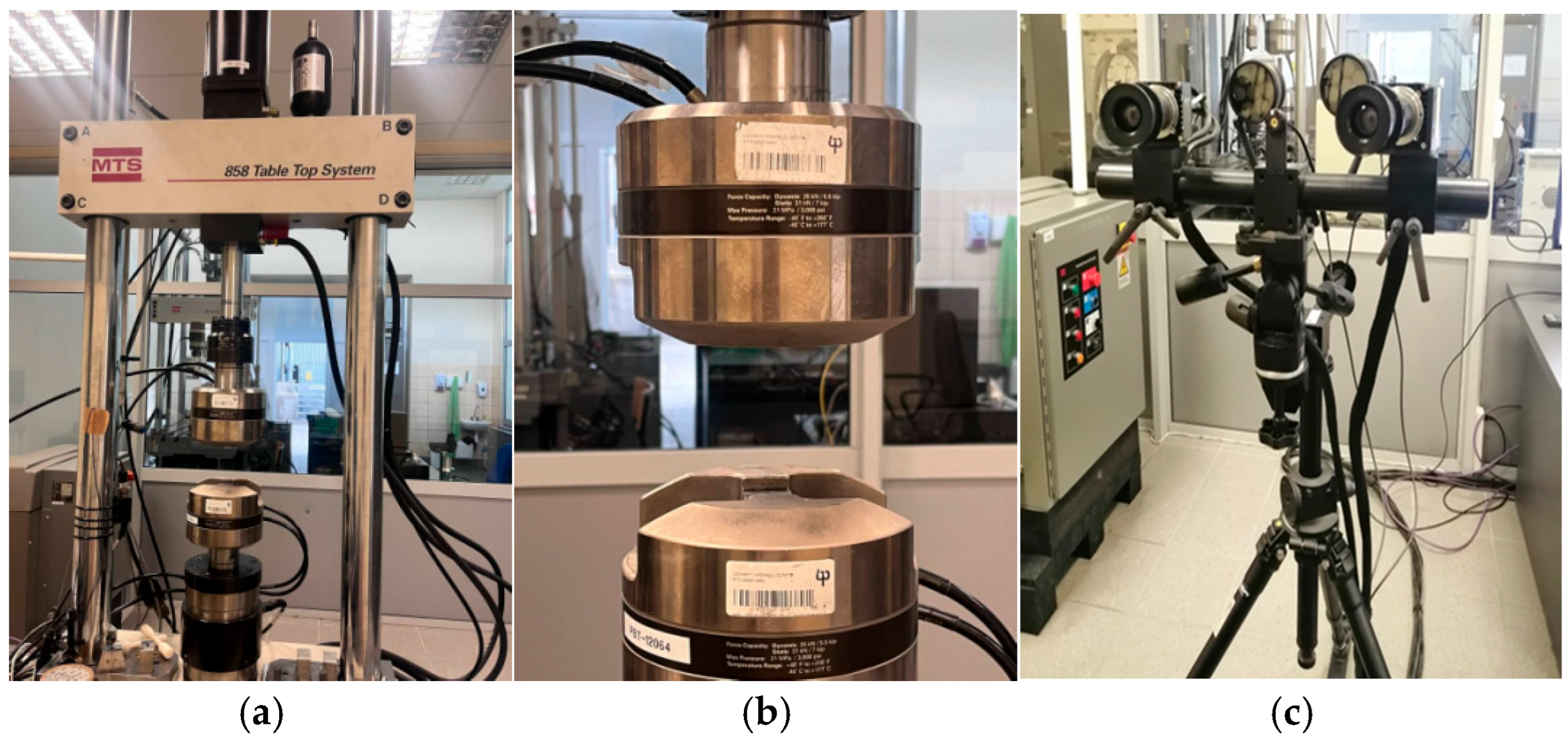
Mechanical properties and porosity. The MTS 858 Table Top System (Bialystok University of Technology, Bialystok, Poland) was used to carry out static tensile tests on different composition scaffold samples (MTS Sytem Corporation, Eden Prairie, MN, USA). It is a compact, servo-hydraulic testing machine designed for precise mechanical testing of materials and components. These servo-hydraulic test systems deliver the performance, adaptability, and precision required to accurately describe the dynamic and static properties of a wide range of biomedical materials and components. It is paired with non-contact measurement systems, ARAMIS 3D DIC, to capture full-field strain data during loading [21] (Figure 3). Thus, the specimen was placed in the testing machine (Figure 3a) and subjected to compressive loading (Figure 3b). The camera system (Figure 3c) recorded the data for precise measurement of the specimen. Using this experimental method, basic material properties and engineering stress–strain curves were determined, including elastic modulus, yield strength, ultimate tensile strength, and plastic elongation.

3. Results and Discussion

3.1. Morphological Characterization

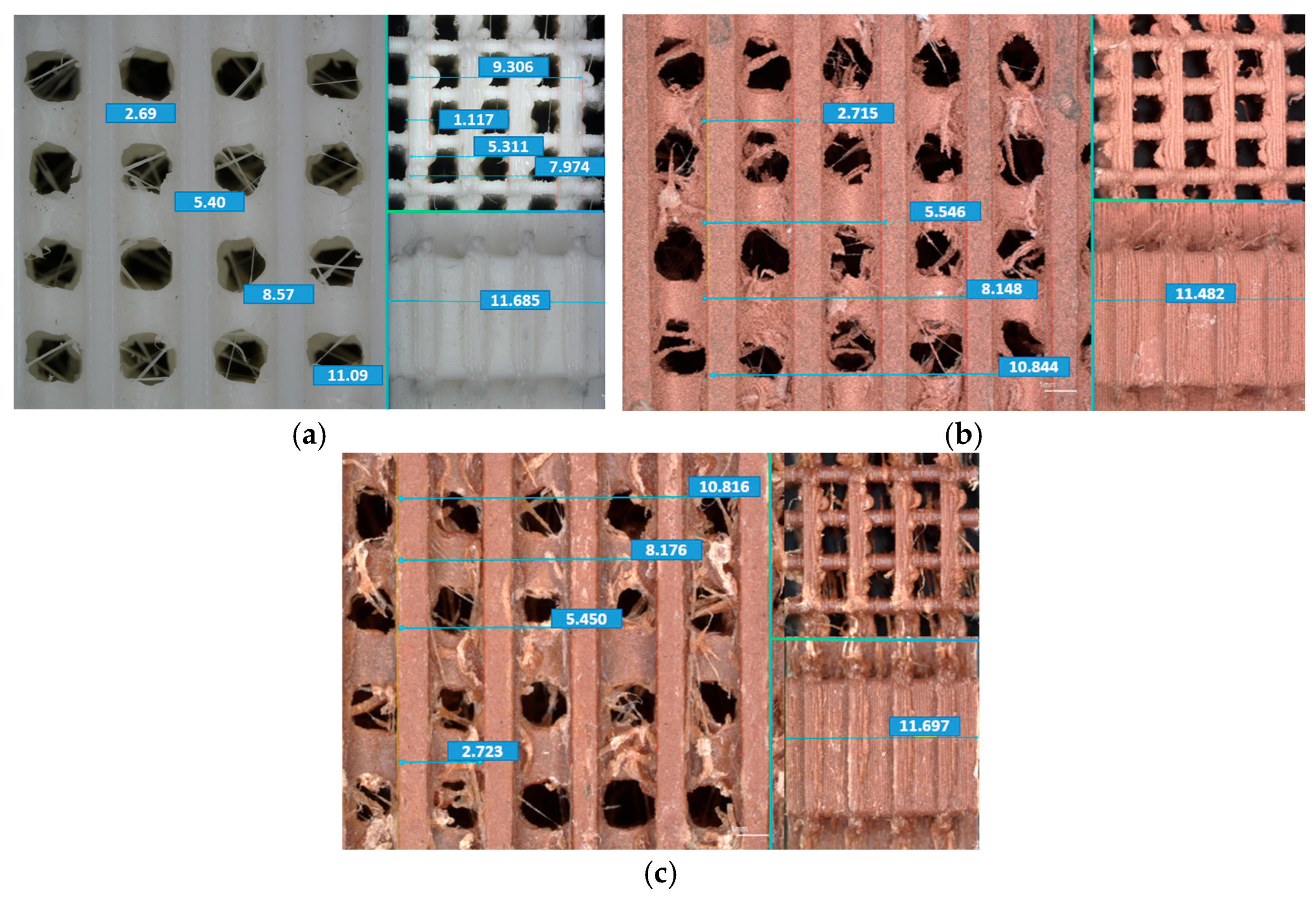
First, the morphological characterization of the fabricated scaffolds was performed using an optical microscope with 100× magnification. It enables evaluation of pore architecture, size, spacing, and geometry. These parameters have a high impact on the mechanical performance and biological functionality of the scaffolds. As the results showed, all three samples had a regular lattice architecture with pores arranged in an orderly manner (Figure 4).
The pore size of different scaffolds ranged from approximately 2.6 mm to 2.7 mm, while the distances between structural filaments ranged from approximately 5.4 mm to 11.7 mm, depending on the measurement direction (Figure 4). Scaffolds exhibit a well-defined, uniform pore structure, and the observed cracks were continuous and evenly spaced, demonstrating good control of the manufacturing parameters.
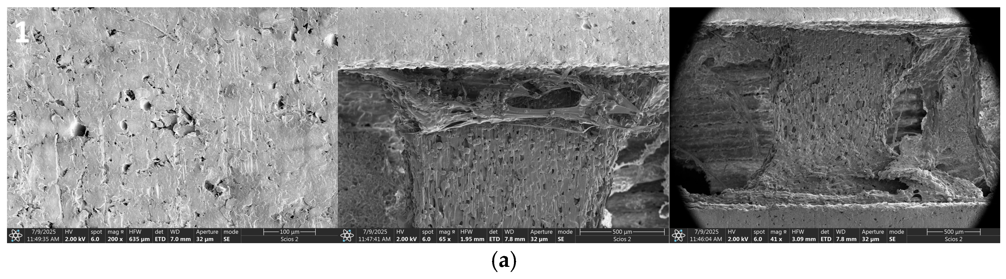
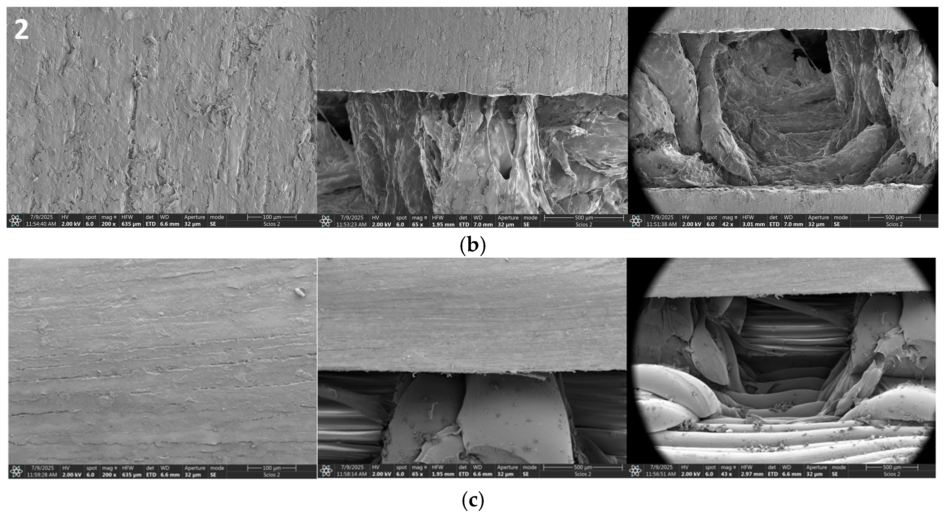
A scanning electron microscope was used to investigate the surface morphology. This experimental method allows the viewing of not only how the HA particles are distributed but also how porous the composite is. Thus, SEM images revealed the dispersion and spatial arrangement of hop particles within the polymer matrix of the porous structure, showing increased surface area and cell infiltration, which are advantageous characteristics for tissue engineering scaffolds (Figure 5).
Scaffold Sample 1 (Figure 5a) had a relatively dense surface morphology and low porosity, which may lead to better mechanical strength, but could limit cell infiltration and nutrient transportation compared to more porous scaffolds. Scaffold Sample 2 (Figure 5b) exhibited more heterogeneous morphology with some visible structural irregularities. It may indicate differences in the dispersion of materials with weaker bonding within the composite matrix, leading to higher porosity in some regions. However, higher porosity compared to Sample 1 may have improved biological performance due to better cell penetration, nutrient diffusion, and vascularization within the scaffold. Scaffold Sample 3 (Figure 5c) demonstrated a more porous and well-fabricated microstructure compared to the other two. Thus, high porosity may increase biological interactions between the scaffold and surrounding tissue.

3.2. Chemical Composition

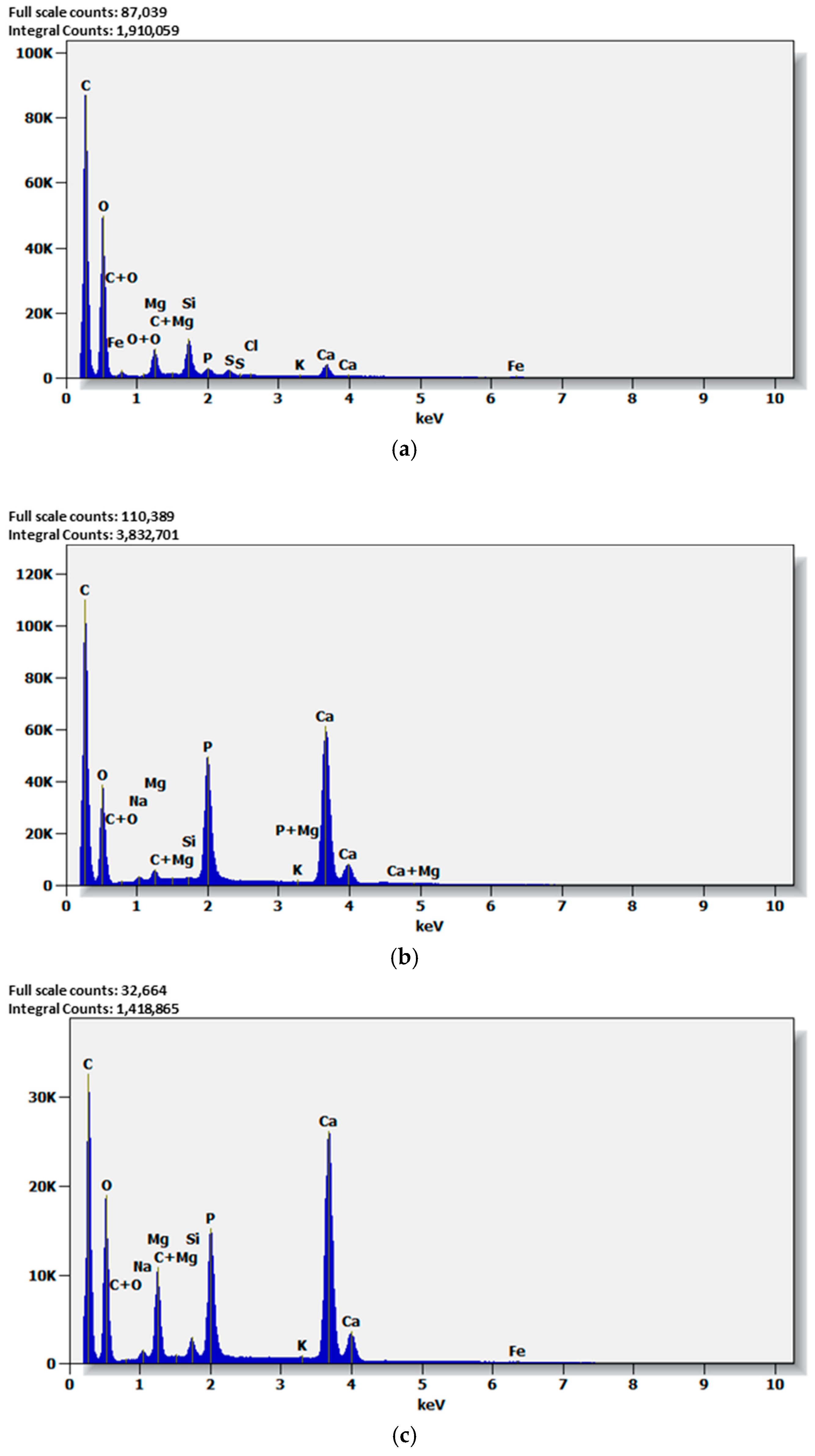
Energy Dispersive Spectroscopy (EDS) analysis was conducted to identify the elemental composition of the fabricated scaffolds and to verify the successful integration of hydroxyapatite (HA) and magnesium (Mg) within the polymer matrix. All three spectra confirmed the presence of carbon (C), oxygen (O), calcium (Ca), phosphorus (P), and magnesium (Mg), which were characteristic elements of the polymer matrix and hydroxyapatite phase (Figure 6). Based on the results, carbon and oxygen peaks indicated a polymer matrix. Calcium and phosphorus peaks indicated the presence of hydroxyapatite and magnesium in all three samples.
Therefore, the EDS results (Figure 6) verified that hydroxyapatite and magnesium were present in the polymer matrix, confirming the composites’ desired chemical composition suitable for bone-tissue engineering applications. As the latest researched state, the inclusion of bioactive inorganic phases (e.g., HA and Mg) is known to support osteoconductivity and bone regeneration [4,16,17]. Thus, there is potential for bone regeneration in composite scaffolds, making them promising materials for bone-tissue engineering applications.
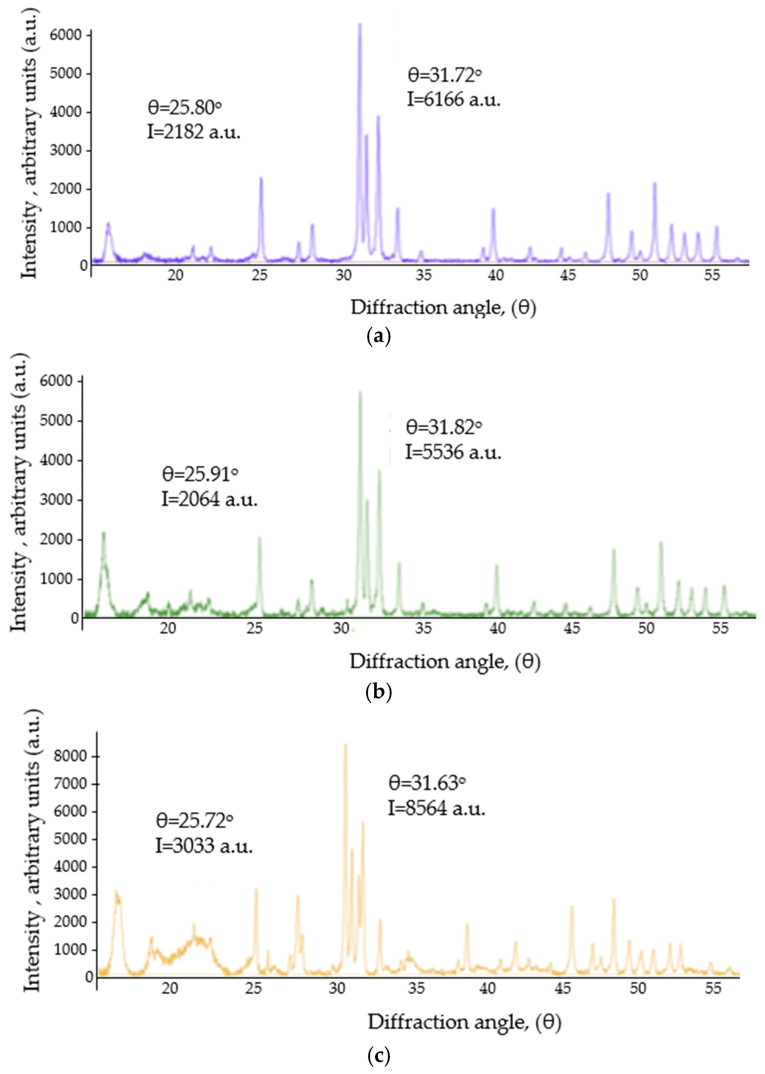
Further structural analysis of the fabricated composites was conducted using X-ray Diffraction (XRD) to identify the crystalline phases, crystal structure, and degree of crystallinity of the materials. XRD is very useful in bone regeneration scaffolds because it may detect inorganic bioactive phases like hydroxyapatite. It also may show how the incorporation of additional materials into the polymer matrix influences the structure and whether the scaffold materials effectively replicate the structural features of bone minerals. A significant observation in the diffractograms was the presence of characteristic reflections around θ ≈ 25.7–25.9° and θ ≈ 31.6–31.8° (Figure 7). Typically, these reflections are associated with the crystalline structure of hydroxyapatite, and their presence confirms the presence of the apatite phase in composites containing HA. It indicates a hydroxyapatite-like mineral content, which is highly desirable because HA is chemically similar to the mineral component of natural bone.
Phase identification was performed based on characteristic diffraction peaks of hydroxyapatite. Thus, the polymer matrix was predominantly amorphous and contributed to the broad background. Results of XRD showed that in Sample 1 (Figure 7a), the main peaks were observed at 25.80° (I = 2182) and 31.72° (I = 6166). In Sample 2 (Figure 7b), the main peaks were observed at 25.91° (I = 2064) and 31.82° (I = 5536), and in Sample 3 (Figure 7c), the main peaks were observed at 25.72° (I = 3033) and 31.63° (I = 8564). It could lead to improved crystallinity and enhanced performance in mimicking the natural bone environment.

3.3. Evaluation of Wettability

The wettability test was carried out to evaluate the degree to which a surface repels or absorbs water. During the experiment, the distilled water was used to measure the contact angle between the liquid and the sample surface before and after polishing (Table 2). Contact angle measurement is a widely used method for characterizing surface–liquid interactions in biomaterials. It offers indirect yet significant information about surface energy, roughness, chemical composition, and potential biological response. In scaffold materials used for bone-tissue engineering, wettability plays a crucial role as it affects initial protein adsorption, cell attachment, spreading, proliferation, and, ultimately, tissue integration.
The wettability test results (Table 2) indicated that Sample 2 had the highest contact angle both before and after polishing, suggesting it had the lowest wettability and the most hydrophobic surface among all tested samples. In contrast, samples 1 and 3 exhibited lower contact angles, indicating higher wettability and hydrophilic behavior compared to Sample 2 and previous research [20].
Moreover, the experimental results suggest that polishing can decrease microscale roughness, eliminate surface defects, and serve as a method to vary surface wettability. Even minor changes in contact angle may affect the biological performance of the scaffolds used for tissue engineering.

3.4. Evaluation of Mechanical Properties

The mechanical behavior of designed scaffolds was evaluated through compression testing using the MTS 858 Table Top System. These results are significant for bone-tissue engineering scaffolds because such materials are expected to provide temporary mechanical support while maintaining a porous architecture conducive to tissue ingrowth. In compression analysis, the stress–strain response provides important insights into the scaffold’s stiffness, load capacity, deformation behavior, and structural stability under applied force. Usually, in a stress–strain diagram, positive stress indicates tension and negative stress indicates compression. Strain at maximum stress, or the strain when the material reaches its limit, is estimated from the X-axis of the stress–displacement graph (Table 3). During the compression test, the samples had multiple measurement points spread across the scaffold structure, showing that dimensional changes or displacement behavior were tracked in different regions of the sample during loading. The stress–strain diagram showed the mechanical response of three different composite scaffold samples under compression. The pictures from ARAMIS cameras (Table 3) clarify the regions where the measurements were taken to evaluate the local stress–strain.
The compression tests showed different mechanical responses among the three composite scaffold samples, showing the impact of their composition and internal porous structure on mechanical behavior (Table 3). Thus, Sample 1 exhibited the highest compressive strength of ~22.5 MPa at a strain of ~0.03, followed by a gradual decrease in stress with increasing strain. Such behavior of the sample demonstrated a strong load capacity and structural integrity. Sample 2 demonstrated a lower maximum stress of ~13.5 MPa at a strain of ~0.08, after which the stress gradually declined as compression continued. In contrast, Sample 3 showed a more complex stress–strain behavior, with an initial peak of ~10.5 MPa, followed by fluctuations in stress as strain increased. These fluctuations showed how stress collapsed and redistributed step by step within the scaffold, indicating a structure that can absorb deformation energy through gradual failure of its internal struts. Overall, the results from compression testing showed that the composite chemical structure significantly influences the mechanical performance of the scaffolds, i.e., Sample 1 had the highest compressive strength and structural stability, whereas Samples 2 and 3 showed lower strength but higher tolerance for deformation. Such mechanical behavior is desirable for bone-tissue engineering, because cancellous bone typically shows compressive strength of 2–12 MPa and modulus of 0.1–5 GPa [22]. It is very important to balance mechanical support with controlled deformation to ensure scaffold stability during tissue regeneration [22,23].
Furthermore, Young’s modulus was used to compare the materials’ stiffness (Table 4). It was evaluated using linear regression on the linear region of the stress–strain curve. The lowest stiffness was observed in Sample 3. Sample 1 showed the highest stiffness, and Sample 2 was between the two. Results indicated that Sample 3 may be useful for applications requiring moderate strength and high elasticity, and Sample 2 is suitable for medium-load applications.
To assess the mechanical performance of the developed scaffolds, a linear eigenvalue buckling analysis was performed using ANSYS 2026 R1 software. Buckling analysis is one of the techniques used to evaluate the stability of structures when subjected to compressive forces. For scaffolds used in bone regeneration, structural stability is essential because the scaffold must sustain its form under physiological loads until new tissue develops. Thus, to prove the relevance of the obtained experimental results, an eigenvalue buckling analysis was performed to evaluate the structure’s buckling under pressure. The first eigenvalue indicated the onset of instability and was used to calculate the critical load. The use of HA in the composite resulted in structural complexity, greater energy absorption, and greater resistance to failure and collapse. Furthermore, the critical load for each sample was determined using the load multiplier (λ), which indicates how many times the applied reference load must be multiplied to reach the buckling point (Table 5). A higher load multiplier signifies greater structural stability and resistance to failure.
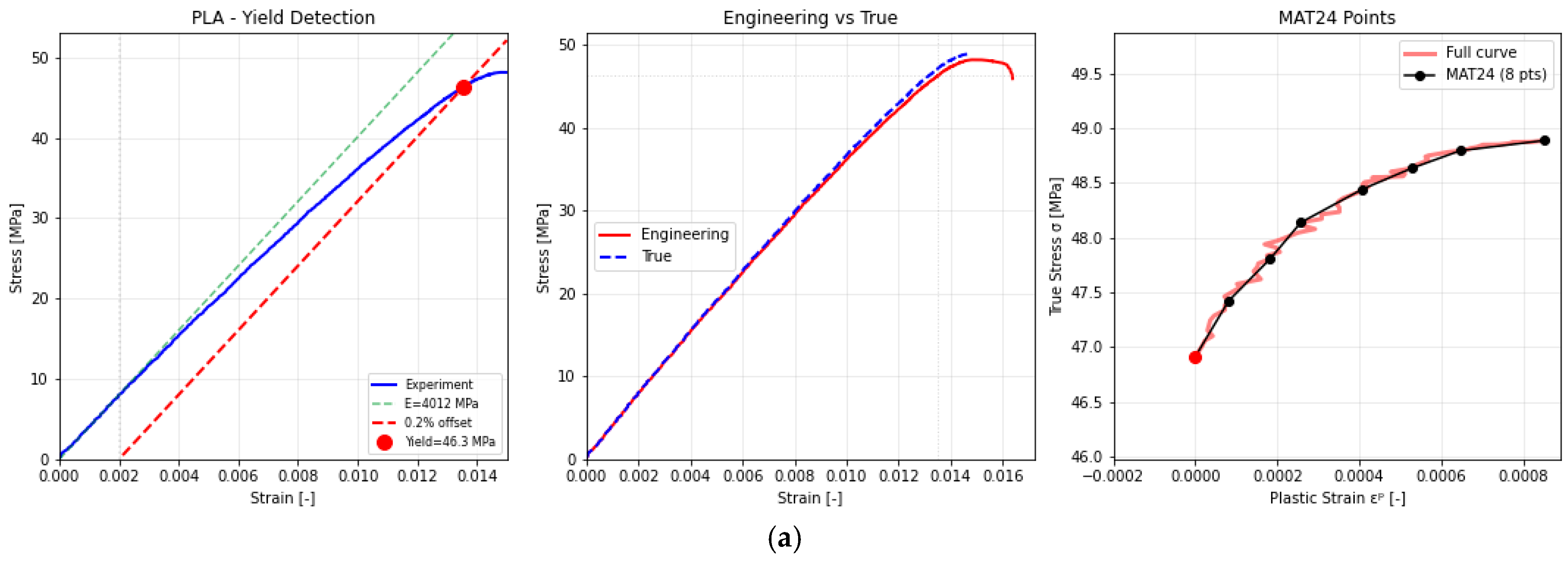
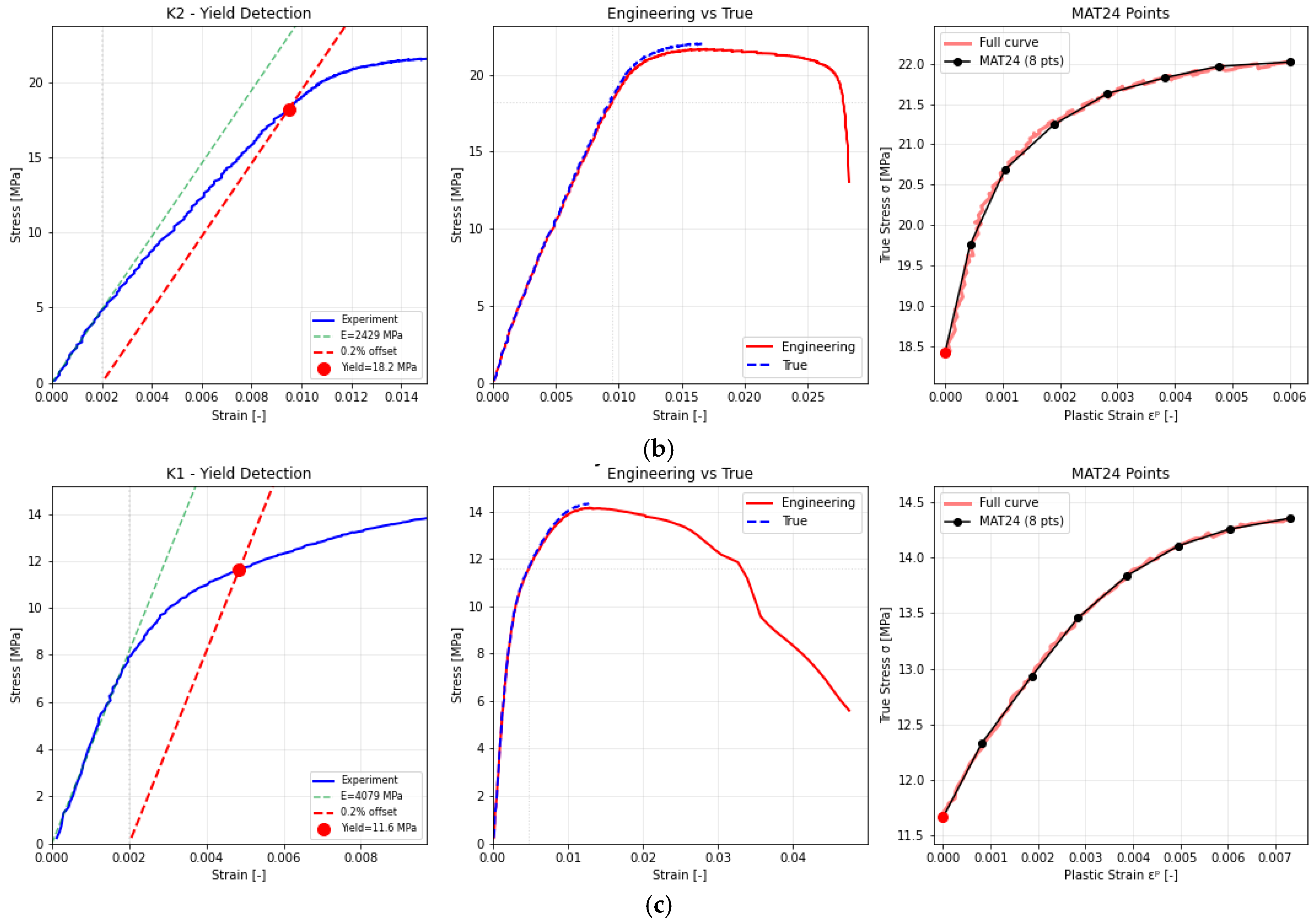
Furthermore, the MAT_024 (Piecewise Linear Plasticity) material model was calibrated and validated using experimental testing data for the three samples under investigation (Figure 8). The calibration process involved identifying the elastic modulus, yield stress, and plastic hardening behavior from the measured stress–strain diagrams. The experimental stress–strain data were transformed into true stress–strain curves and used to establish the piecewise linear plasticity model. The simulation results closely matched the experimental results, verifying the precision of the calibrated material model. This validated model was then employed in finite element simulations, such as the buckling analysis of scaffold structures (Figure 9).
The MAT_024 plasticity model was successfully calibrated for three additively manufactured composite materials (Sample 1, Sample 2, and Sample 3) using experimental stress–strain data (Figure 8). The automated calibration procedure accurately reproduced the distinct mechanical responses of each material variant by selecting eight representative points along the true stress–plastic strain curves. Sample 1 (Figure 8a) exhibited the highest stiffness and strength, with a Young’s modulus of 3.83 GPa, a peak stress of 48.2 MPa at 0.0149 strain, and limited post-peak deformation due to brittle fracture. Sample 2 (Figure 8b) showed intermediate mechanical behavior, characterized by a Young’s modulus of 2.24 GPa, a peak stress of 21.7 MPa at 0.017 strain, and more pronounced plastic softening beyond yielding. Thus, Sample 3 (Figure 8c) exhibited the lowest stiffness and strength, with a Young’s modulus of 3.78 GPa, a yield stress of approximately 11.6 MPa, and a maximum true stress of 14.2 MPa at 0.0129 strain, followed by gradual post-peak softening extending up to 0.047 strain. The linear-elastic region analysis demonstrated excellent agreement between the experimental and simulated data, confirming the accuracy of the automatically determined elastic moduli. The eight-point discretization used in the MAT_024 formulation effectively captured both the elastic–plastic transition and the strain-softening behavior, providing a good balance between computational efficiency and physical realism for nonlinear finite element simulations in ANSYS Mechanical.
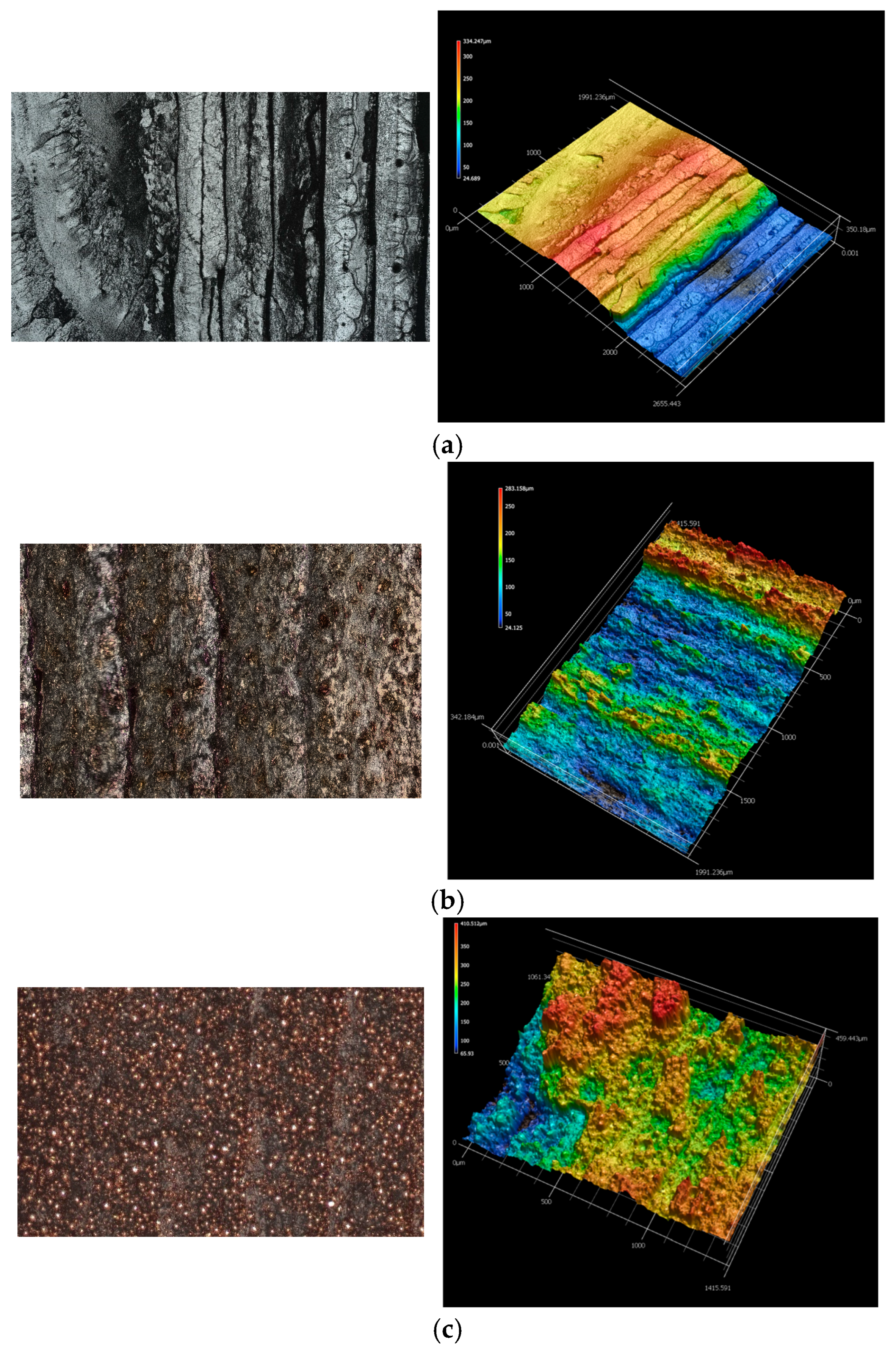
During the compression test, clear differences in the fracture mechanism were observed between samples (Figure 9). In the case of Sample 1, the destruction process was characteristic of brittle materials—smooth interlayer delamination zones and slip bands running parallel to the printing direction were visible on the fracture surface, indicating a dominant contribution of delamination and stress concentration at the layer boundaries. In Sample 2, the fracture process was more controlled—a micro-wavy fracture structure and traces of crack bridging were observed, indicating the involvement of a micro-ductile fracture mechanism and better interfacial load transfer. Sample 3, on the other hand, showed a much more complex fracture pattern: there were clear signs of decohesion at the matrix-filler boundaries, local microcracks, and zones of reinforcement particle pull-out, indicating partial stress redistribution and increased energy dissipation capacity. As a result, this material exhibited greater surface roughness and higher fracture energy compared to Sample 1. Three-dimensional topography analysis confirmed the increasing complexity of the fracture surface in successive materials, which correlates with an increase in fracture energy and crack propagation resistance: from brittle Sample 1, through Sample 3 with a toughening effect, to Sample 2, which achieved the most balanced combination of stiffness and ductility.
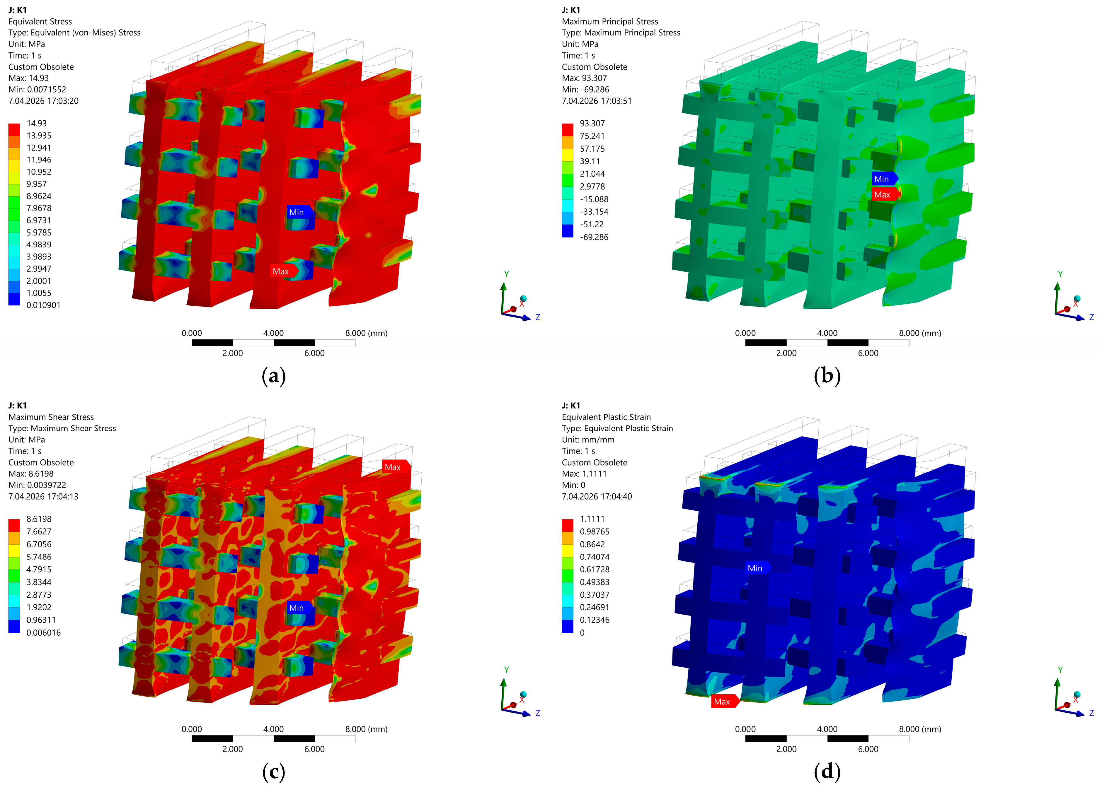
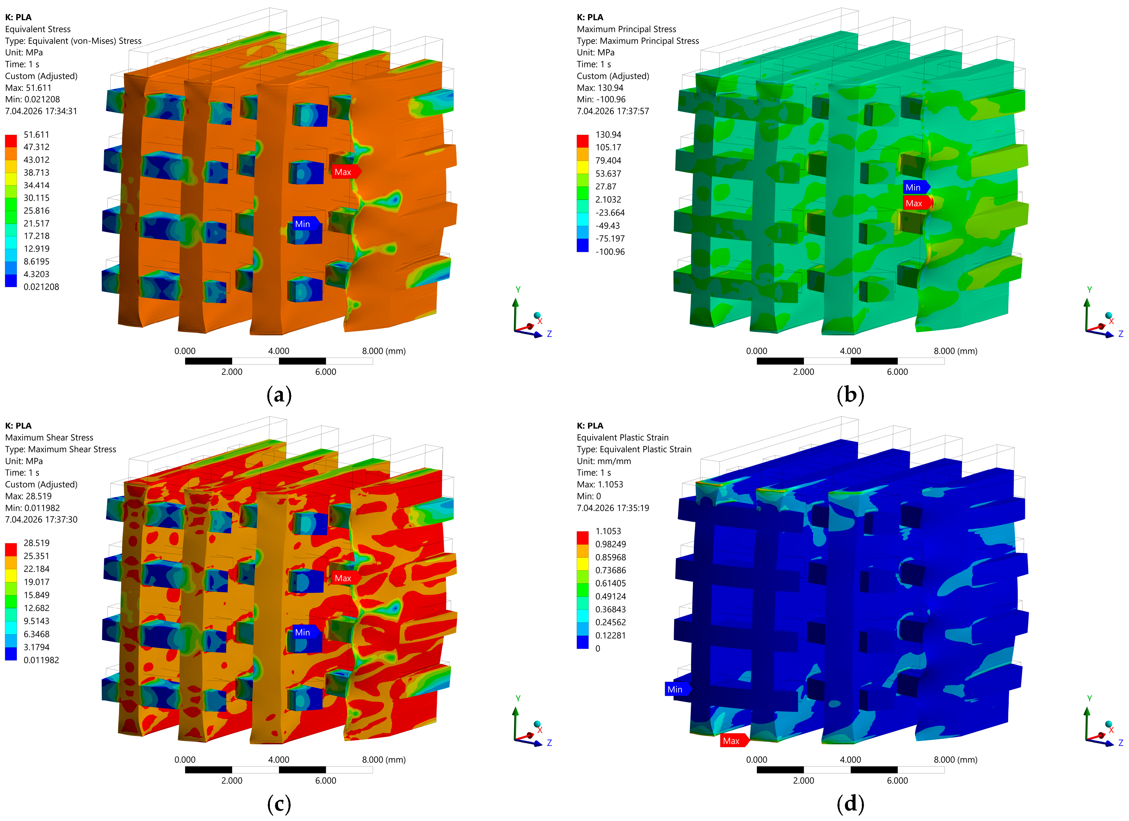
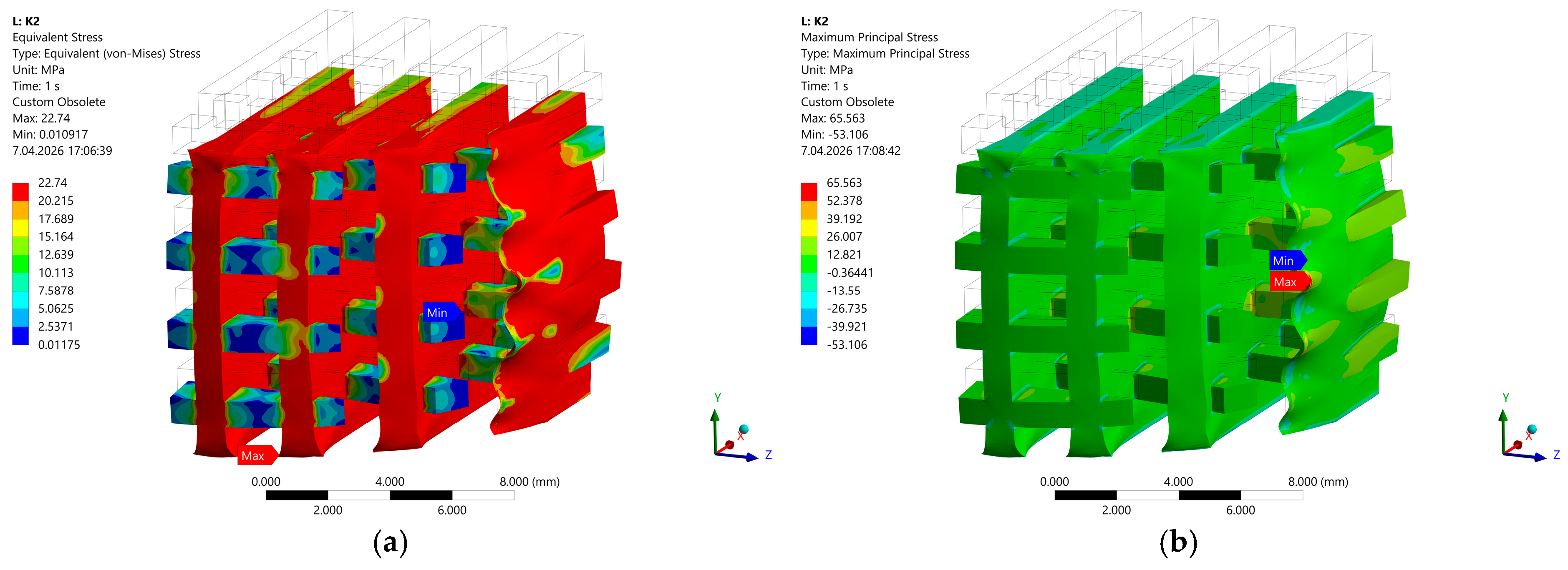
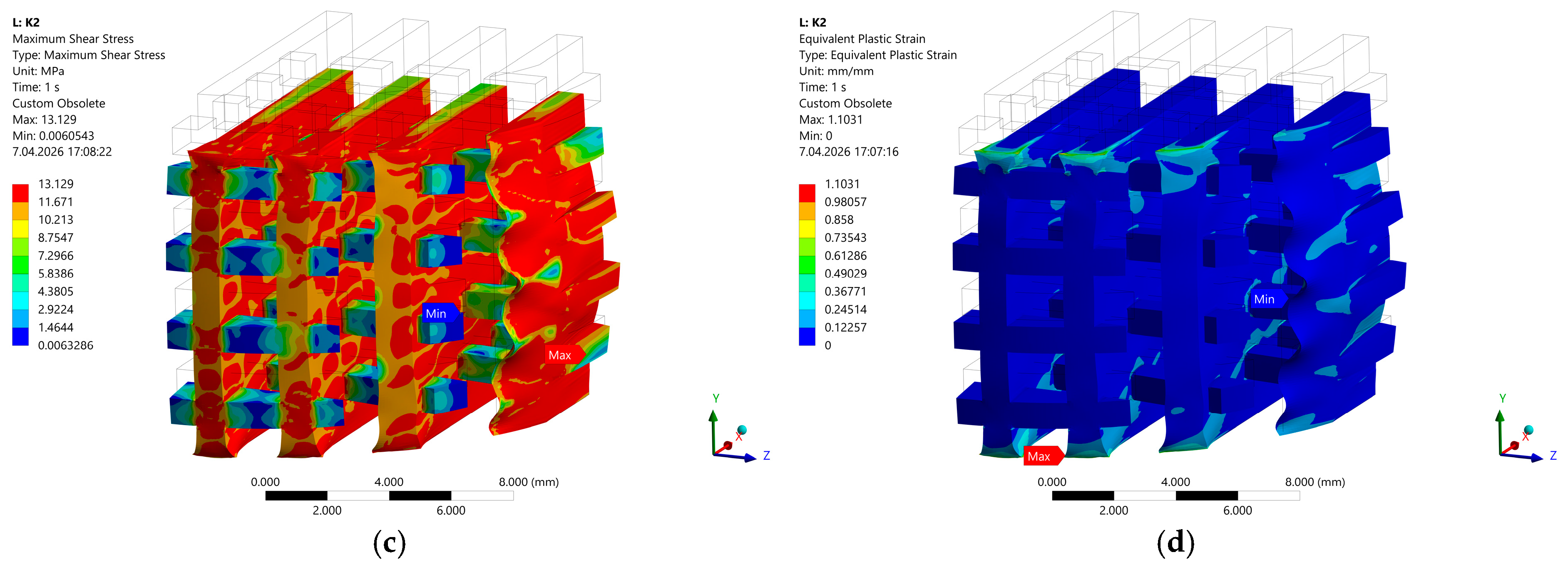
Thus, numerical simulations of stress and strain distribution fields in samples revealed clear differences in the mechanical response of the lattice structures under compression loading (Figure 10, Figure 11 and Figure 12).
For the Sample 1 structure (Figure 10), the highest von Mises stresses exceed 30 MPa and are strongly localized at the inter-rib junctions and inner corners of the cells. The stress concentration leads to early yielding and rapid growth of plastic strains, exceeding 2%, which indicates limited capacity for stress redistribution. The deformation progresses abruptly, confirming the brittle behavior of the unmodified polymer. The Sample 2 structure (Figure 11) shows the most favorable response—the von Mises stresses are homogenized and remain below 20 MPa across most of the volume, with maximum plastic strains 1.4%. The strain field indicates a gradual, ductile deformation mode without abrupt localization. In Sample 3 (Figure 12), the overall stress level is reduced to approximately 22–25 MPa, while the plastic strains remain confined below 1.5%. The presence of the reinforcing phase promotes more uniform load transfer, delaying local plastic flow and enabling partial stress relaxation within the cell walls. This confirms that the hybrid reinforcement in Sample 2 effectively stabilizes the deformation process, suppresses stress concentrations, and increases the elastic load-bearing range compared with both Sample 1 and Sample 3.

4. Conclusions

This research paper examined the structural, chemical, surface, and mechanical properties of three 3D-printed composite scaffolds based on PLA–PHA–PHB polymer matrices, incorporating hydroxyapatite (HA) and magnesium (Mg) particles. The morphological analysis showed that all fabricated scaffolds exhibited a clear, interconnected porous structure, which is crucial for bone-tissue engineering. Thus, the possibility to control pore structure facilitates efficient cell migration, vascularization, and nutrient transport. SEM observations revealed differences in surface microstructure among the composites: Sample 1 showed a relatively dense and compact structure, Sample 2—a more heterogeneous morphology, while Sample 3 demonstrated increased micro-porosity and roughness. Moreover, Sample 2 exhibited the highest contact angle (70.04°), indicating a hydrophobic surface that promotes surface stability and water resistance.
Experimental results of chemical composition indicated that magnesium, calcium, and phosphorus were successfully combined, leading to enhanced bioactivity and compatibility with bone. Sharp peaks at 25.91° and 31.82° were observed in the XRD analysis, indicating good crystallinity and the presence of stable hydroxyapatite.
According to the mechanical study, Sample 2 offered an excellent combination of flexibility (strain = 0.22) and durability, making it suitable for medium-load applications, while Sample 1 showed the maximum hardness (1913 MPa) and strength (22.5 MPa). This was confirmed by buckling analysis. It may be concluded that Sample 2 is generally the most suitable material because it exhibits structural integrity, bioactivity, and desirable surface properties for bone grafts.

Author Contributions

Conceptualization, M.S.R. and G.J.; methodology, M.S.R. and D.M.P.; software, M.S.R. and D.M.P.; validation, M.S.R., G.J. and D.M.P.; formal analysis, W.G., E.B.-P. and S.U.; investigation, M.S.R., W.G., E.B.-P. and S.U.; writing—original draft preparation, M.S.R. and D.M.P.; writing—review and editing, G.J. and S.U.; visualization, M.S.R., W.G., E.B.-P. and D.M.P. All authors have read and agreed to the published version of the manuscript.

Funding

This research received no external funding.

Institutional Review Board Statement

Not applicable.

Informed Consent Statement

Not applicable.

Data Availability Statement

Data is contained within the article.

Conflicts of Interest

The authors declare no conflicts of interest.

References

  1. Kolan, K.C.; Semon, J.A.; Bindbeutel, A.T.; Day, D.E.; Leu, M.C. Bioprinting with bioactive glass loaded polylactic acid composite and human adipose stem cells. Bioprinting 2020, 18, e00075. [Google Scholar] [CrossRef] [Scilit]
  2. Karthic, C.V.M.; Chockalingam, K. Enhancement of mechanical and biological properties of PEEK/GO/HA composite scaffolds fabricated through 3D printing and sintered process for bone tissue engineering. Polym.-Plast. Technol. Mater. 2025, 64, 46–62. [Google Scholar] [CrossRef] [Scilit]
  3. Lee, J.S.; Jung, H.; Ajiteru, O.; Lee, O.J.; Kim, S.H.; Park, H.S.; Park, C.H. Hybrid 3D bioprinting for advanced tissue-engineered trachea: Merging fused deposition modeling (FDM) and topdown digital light processing (DLP). Biofabrication 2024, 17, 015026. [Google Scholar] [CrossRef] [Scilit]
  4. Ali, F.; Kalva, S.N.; Mroue, K.H.; Keyan, K.S.; Tong, Y.; Khan, O.M.; Koç, M. Degradation assessment of Mg-incorporated 3D printed PLA scaffolds for biomedical applications. Bioprinting 2023, 35, e00302. [Google Scholar] [CrossRef] [Scilit]
  5. Huang, B.; Caetano, G.; Vyas, C.; Blaker, J.J.; Diver, C.; Bártolo, P. Polymer-ceramic composite scaffolds: The effect of hydroxyapatite and -tri-calcium phosphate. Materials 2018, 11, 129. [Google Scholar] [CrossRef] [Scilit]
  6. Feng, Y.; Zhu, S.; Mei, D.; Li, J.; Zhang, J.; Yang, S.; Guan, S. Application of 3D printing technology in bone tissue engineering: A review. Curr. Drug Deliv. 2020, 18, 847–861. [Google Scholar] [CrossRef] [Scilit]
  7. Wang, Z.; Sun, Y.; Li, C. Advances in 3D printing technology for preparing bone tissue engineering scaffolds from biodegradable materials. Front. Bioeng. Biotechnol. 2024, 12, 1483547. [Google Scholar] [CrossRef] [Scilit]
  8. Ojo, S.A.; Abere, D.V.; Adejo, H.O.; Robert, R.A.; Oluwasegun, K.M. Additive manufacturing of hydroxyapatite-based composites for bioengineering applications. Bioprinting 2023, 32, e00278. [Google Scholar] [CrossRef] [Scilit]
  9. Kang, H.; Jiang, X.; Liu, Z.; Liu, F.; Yan, G.; Li, F. Biodegradable 3D printed scaffolds of modified poly (trimethylene carbonate) composite materials with poly (l-lactic acid) and hydroxyapatite for bone regeneration. Nanomaterials 2021, 11, 3215. [Google Scholar] [CrossRef] [Scilit] [PubMed]
  10. Angela Snchez-Cepeda, P.-A.L.; Pazos, M.C. Functionalization of 3D printed poly(lactic acid)/graphene oxide/-tricalcium phosphate (PLA/GO/TCP) scaffolds for bone tissue regeneration application. RSC Adv. 2024, 14, 39804–39819. [Google Scholar] [CrossRef] [Scilit] [PubMed]
  11. Pérez-Davila, S.; Potel-Alvarellos, C.; Carballo, R.; González-Rodríguez, L.; López-Álvarez, M.; Serra, J.; Díaz-Rodríguez, P.; Landín, M.; González, P. Vancomycin-loaded 3D-printed polylactic AcidHydroxyapatite scaffolds for bone tissue engineering. Polymers 2023, 15, 4250. [Google Scholar]
  12. Nalesso, P.R.L.; Vedovatto, M.; Gregório, J.E.S.; Huang, B.; Vyas, C.; Santamaria, M., Jr.; Bártolo, P.; Caetano, G.F. Early in vivo osteogenic and inflammatory response of 3D printed polycaprolactone/carbon nanotube/hydroxyapatite/tricalcium phosphate composite scaffolds. Polymers 2023, 15, 2952. [Google Scholar] [CrossRef] [Scilit] [PubMed]
  13. Askarzadeh, N.; Sherafat, Z.; Sani, M.; Azarpira, N. Development of hybrid polyvinylidene FluorideBarium titanate/polyvinyl AlcoholHydroxyapatite CoElectrospun piezoelectric scaffold as a stimulator for bone tissue regeneration. Polym. Adv. Technol. 2024, 35, e70016. [Google Scholar] [CrossRef] [Scilit]
  14. Alksne, M.; Kalvaityte, M.; Simoliunas, E.; Rinkunaite, I.; Gendviliene, I.; Locs, J.; Rutkunas, V.; Bukelskiene, V. In vitro comparison of 3D printed polylactic acid/hydroxyapatite and polylactic acid/bioglass composite scaffolds: Insights into materials for bone regeneration. J. Mech. Behav. Biomed. Mater. 2020, 104, 103641. [Google Scholar] [CrossRef] [Scilit] [PubMed]
  15. Alonso-Fernández, I.; Haugen, H.J.; López-Peña, M.; González-Cantalapiedra, A.; Muñoz, F. Use of 3D-printed polylactic acid/bioceramic composite scaffolds for bone tissue engineering in preclinical in vivo studies: A systematic review. Acta Biomater. 2023, 168, 1–21. [Google Scholar] [CrossRef] [Scilit]
  16. Zhang, B.; Wang, L.; Song, P.; Pei, X.; Sun, H.; Wu, L.; Zhou, C.; Wang, K.; Fan, Y.; Zhang, X. 3D printed bone tissue regenerative PLA/HA scaffolds with comprehensive performance optimizations. Mater. Des. 2021, 201, 109490. [Google Scholar] [CrossRef] [Scilit]
  17. Ansari, N.F.; Annuar, M.S.M.; Murphy, B.P. A porous medium-chain-length poly(3-hydroxyalkanoates)/hydroxyapatite composite as scaffold for bone tissue engineering. Eng. Life Sci. 2016, 17, 420–429. [Google Scholar] [CrossRef] [Scilit]
  18. Bhattacharjee, A.; Bose, S. 3D printed hydroxyapatite—Zn2+ functionalized starch composite bone grafts for orthopedic and dental applications. Mater. Des. 2022, 221, 110903. [Google Scholar] [CrossRef] [Scilit]
  19. Oliver-Urrutia, C.; Kashimbetova, A.; Slámečka, K.; Casas-Luna, M.; Matula, J.; Koledova, Z.S.; Kaiser, J.; Čelko, L.; Montufar, E.B. Porous titanium/hydroxyapatite interpenetrating phase composite/s with optimal mechanical and biological properties for personalized bone repair. Biomater. Adv. 2025, 166, 214079. [Google Scholar] [CrossRef] [Scilit]
  20. Raziyan, M.S.; Palevicius, A.; Perkowski, D.; Urbaite, S.; Janusas, G. Development and Evaluation of 3D-Printed PLA/PHA/PHB/HA Composite Scaffolds for Enhanced Tissue-Engineering Applications. J. Compos. Sci. 2024, 8, 226. [Google Scholar] [CrossRef] [Scilit]
  21. Estévez, M.; Batoni, E.; Cicuéndez, M.; Bonatti, A.F.; Fernández-Marcelo, T.; De Maria, C.; González, B.; Izquierdo-Barba, I.; Vozzi, G. Fabrication of 3D biofunctional magnetic scaffolds by combining fused deposition modelling and inkjet printing of superparamagnetic iron oxide nanoparticles. Tissue Eng. Regen. Med. 2025, 2, 627–646. [Google Scholar] [CrossRef] [Scilit]
  22. Shi, Z.; Huang, G.; Li, Z.; Lou, Z.; Gong, Z.; Wang, X.; Li, C.; Wang, B. A PLA–tPU Based Magnesium Ion Incorporated CSH/nHA Bioactive Porous Composite Scaffold for Critical Bone Defect Repair. Mater. Adv. 2023, 4, 3583–3592. [Google Scholar] [CrossRef] [Scilit]
  23. Wu, S.; Liu, X.; Yeung, K.W.K.; Liu, C.; Yang, X. Biomimetic Porous Scaffolds for Bone Tissue Engineering. Mater. Sci. Eng. R Rep. 2014, 80, 1–36. [Google Scholar] [CrossRef] [Scilit]
Figure 1. Schematic diagram of the preparation and production of polymer-ceramic composites using the 3D printing method.
Applsci 16 03647 g001
Figure 2. Design of a porous cylinder in SolidWorks.
Applsci 16 03647 g002
Figure 3. Measurement setup for mechanical testing of composite 3D-printed samples, including (a) the MTS 858 Table Top System, (b) force and displacement sensors, and (c) the ARAMIS 3D DIC optical correlation system.
Applsci 16 03647 g003
Figure 4. Microscopic views of different composite scaffolding structures: (a) Sample 1, (b) Sample 2, and (c) Sample 3 (size is in mm).
Applsci 16 03647 g004
Figure 5. SEM images of three different composite scaffold samples: (a) Sample 1, (b) Sample 2, and (c) Sample 3.
Applsci 16 03647 g005aApplsci 16 03647 g005b
Figure 6. EDS spectra of the composites: (a) Sample 1, (b) Sample 2, and (c) Sample 3.
Applsci 16 03647 g006
Figure 7. XRD patterns of composites (Ka2 radiation removed): (a) Sample 1, (b) Sample 2, and (c) Sample 3 showing characteristic hydroxyapatite peaks around 2θ ≈ 25.8° and 31.7°.
Applsci 16 03647 g007
Figure 8. Calibration and validation of the MAT_024 (Piecewise Linear Plasticity) model for three 3D-printed composite materials based on experimental results: (a) Sample 1, (b) Sample 2, and (c) Sample 3.
Applsci 16 03647 g008aApplsci 16 03647 g008b
Figure 9. Comparison of microstructures and 3D topography of fracture surfaces after experimental test and 3D topographic maps corresponding to individual materials: (a) microscopic fracture structure of Sample 1, (b) Sample 2 with a micro-wavy structure and crack bridging, (c) Sample 3 composite with characteristic areas of decohesion.
Applsci 16 03647 g009
Figure 10. Distribution of stress and strain fields in the Sample 1 structure: (a) von Mises Stress, (b) Maximum Principal Stress, (c) Equivalent Elastic Strain, (d) Maximum Principal Elastic Strain.
Applsci 16 03647 g010
Figure 11. Distribution of stress and strain fields in the Sample 2 structure: (a) von Mises Stress, (b) Maximum Principal Stress, (c) Equivalent Elastic Strain, (d) Maximum Principal Elastic Strain.
Applsci 16 03647 g011aApplsci 16 03647 g011b
Figure 12. Distribution of stress and strain fields in the Sample 3 structure: (a) von Mises Stress, (b) Maximum Principal Stress, (c) Equivalent Elastic Strain, (d) Maximum Principal Elastic Strain.
Applsci 16 03647 g012
Table 1. Preparation of samples.
SamplePLA
(wt. %)
PHA
(wt. %)
PHB
(wt. %)
Mg
(wt. %)
HA
(wt. %)
180555.05
23030255.010
3040405.015
Table 2. Contact angle of composite structures measured before and after polishing.
SampleBefore Polish-Average AngleSmooth Surface-Average Angle
152.56 ± 0.02°50.37 ± 0.02°
273.80 ± 0.02°70.04 ± 0.02°
350.08 ± 0.02°49.12 ± 0.02°
Table 3. Mechanical properties of composites obtained by compression test.
SampleMeasurement Points on the SpecimenStress–Strain Diagram
1Applsci 16 03647 i001Applsci 16 03647 i002
2Applsci 16 03647 i003Applsci 16 03647 i004
3Applsci 16 03647 i005Applsci 16 03647 i006
Table 4. Young modulus, stress, and strain of the composites.
SampleYoung Modulus MPaStress MPaStrain [µε]
1191322.50.012
2392.5813.50.22
3370.8210.50.28
Table 5. Load multiplier (λ) of different composites obtained from linear buckling simulation in ANSYS.
Load Multiplier (λ)Sample 1Sample 2Sample 3
12.38322.37962.3786
22.78752.78322.782
33.20963.20473.2035
Disclaimer/Publisher’s Note: The statements, opinions and data contained in all publications are solely those of the individual author(s) and contributor(s) and not of MDPI and/or the editor(s). MDPI and/or the editor(s) disclaim responsibility for any injury to people or property resulting from any ideas, methods, instructions or products referred to in the content.