Article

4E Analysis of Alternative Configurations in Mobile Air Conditioning Used in Electromobility and Conventional Vehicles


by
D. Méndez-Méndez
1,
J. F. Ituna-Yudonago
2,
J. J. Ramírez-Minguela
3,
J. M. Belman-Flores
1 and
V. Pérez-García
1,*
1
IRSE Research Group, Department of Mechanical Engineering, University of Guanajuato, Carretera Salamanca-Valle de Santiago, km 3.5+1.8, Salamanca 36885, Guanajuato, Mexico
2
Aeronautical Engineering Department, Universidad Politécnica Metropolitana de Hidalgo, Boulevard Acceso a Tolcayuca 1009, Ex Hacienda de San Javier, Tolcayuca 43860, Hidalgo, Mexico
3
Department of Chemical Engineering, Division of Natural and Exact Sciences, University of Guanajuato, Col. Noria Alta s/n, Guanajuato 36050, Guanajuato, Mexico
*
Author to whom correspondence should be addressed.
Appl. Sci. 2026, 16(6), 3071; https://doi.org/10.3390/app16063071
Submission received: 9 February 2026 / Revised: 7 March 2026 / Accepted: 16 March 2026 / Published: 22 March 2026
(This article belongs to the Special Issue Novel Ecofriendly Refrigeration System: Technology and Application)

Abstract

This study analyzes four alternative cycle configurations for the traditional vapor compression system used in conventional, hybrid, and electric vehicles, taking low-GWP alternatives for the substitution of R134a. These are cycle with an internal heat exchanger and thermostatic expansion valve (IHX + TEV); cycle with an internal heat exchanger and short tube (IHX + ST); cycle with an ejector (EC); and cycle with an ejector and internal heat exchanger (EC + IHX). Similarly, the energy, exergy, exergoeconomic, and environmental impact of these configurations were analyzed using synthetic refrigerants with a GWP of less than 150. The results indicate that, using the EC + IHX configuration, the COP for refrigerants R1234yf, R1234ze(E), R1243zf, and R516A is the highest, increasing by more than 20%. Using R1243zf in the EC configuration can reduce the total cost ratio compared to other refrigerants. On the other hand, the use of IHX cycle configurations with R444A and R445A decreases the exergy efficiency and increases the total cost ratio by up to 35% and 70%, respectively. Additionally, the Total Equivalent Warming Impact (TEWI) analysis showed reductions up to 20% for ejector cycle configurations using R1234ze(E), R1234yf, R1243zf, and R516A.

1. Introduction

In mobile air conditioning (MAC) systems, one of the most commonly used refrigerants is hydrofluorocarbon (HFC) R134a, which has a high Global Warming Potential (GWP = 1430) [1]. In this application, R134a replaced R12 in new systems after implementing the Montreal Protocol in 1987 [2]. This refrigerant is the main greenhouse gas emission factor in MAC systems, and according to reports, it is estimated that the annual leakage rate of R134a can reach 6–9% of the initial charge [3]. For this reason, its progressive elimination has been proposed worldwide, establishing a reduction horizon for 2030 in developed countries and 2045 in underdeveloped countries [4].
In 2006, the European Union approved Directive 2006/40/EC to reduce emissions of fluorinated gases [5]. This regulation has been updated since its enactment. In this sense, the most recent renewal of this regulation came into force on 11 March 2024, with the specification of Regulation (EU) 2024/573, which amends Directive (EU) 2019/1937 and repeals Regulation (EU) 517/2014. In this new regulation, air conditioners and heat pumps with nominal capacities up to 12 kW that use refrigerants with a GWP > 150 will be banned as of 2027. Furthermore, this regulation supports the search established by its predecessors, which had proposed limiting refrigerants with a GWP greater than 150 in new vehicles since 2011 and for all new vehicle production since 2017 [6]. Similar restrictions have been applied in America. For example, in the United States, the use of refrigerants in MAC systems was regulated, establishing that, as of 2020, the inclusion of refrigerants in this technology must have a GWP lower than 150 [7].
The guidelines for regulations on the use of refrigerants in MAC systems are consistent with the implementation of the Paris Agreement (2015) and the Kigali Amendment (2016) to the Montreal Protocol, through which it seeks to maintain an increase of less than 0.5 °C in global warming by the end of this century, through a strict reduction in HFCs [8]. However, the climate situation is alarming; according to the United Nations, the global warming transition has ended, and global boiling has begun, where, according to reports, July 2023 has been the hottest month on record. If the reduction objectives are not strictly followed, then there will most likely be an increase of more than 1.5 °C in the Earth’s average temperature in the next five years [9,10].
Based on the above, research on refrigerants in MAC systems has focused on environmentally friendly alternative fluids that represent a low direct impact as a function of their GWP and are competitive with the target refrigerants replaced in this technology. In Europe, for example, the research horizon is directed to new systems with alternative refrigerants such as hydrofluorolefins (HFOs) and natural refrigerants in this type of application, as shown in Table 1.
The theoretical–experimental research on MAC systems, regarding the availability of low-GWP refrigerants that satisfy current regulations, highlights some pure HFOs (R1234yf, R1234ze(E) and R1243zf), some HFCs (R152 and R161), HFO/HFC mixtures (R444A, R445A, R516A), some hydrocarbons (R290, R600, R600a), and R744 as natural refrigerants [12].
The ultra-low-GWP R1234yf has been considered the leading candidate in several studies to replace R134a in MAC systems [13,14,15,16,17]. Meanwhile, another pure HFO that appears as an option in this application is R1234ze(E), which has similar properties to R134a and R1234yf. However, research on this refrigerant has reflected a low performance [18,19,20]. Although pure HFO refrigerants have been tested for use in MAC, due to their A2L flammability classification imposed by ASHRAE, most commercial vehicle manufacturers have not approved the use of these refrigerants due to flammability risks [21]. However, some results have shown that medium flammability refrigerants are suitable for systems operating with low refrigerant charges [22].
HFC/HFO refrigerant blends also represent an alternative to R134a in MAC systems. Some have a slight flammability and are blends of low GWP. For example, R445A has a GWP of 146, is a blend of HFC/HFO, and has been presented as an alternative in MAC systems. Among the works that have evaluated this refrigerant is the one by Devecioglu and Oruc [21], who compared through a theoretical analysis the energy performance of R445A with R1234yf and R444A for typical MAC operating conditions, obtaining a higher cooling capacity of R445A compared to R1234yf; however, the COP was lower. Additionally, Poongavanam et al. [23] employed various MCDM (Multicriteria Decision-Making Methodology) methods to select the most suitable refrigerant for the MAC system. The authors made a comparison based on thermophysical properties, environmental characteristics, and economic factors, concluding that R445A was the second-best option for this type of application.
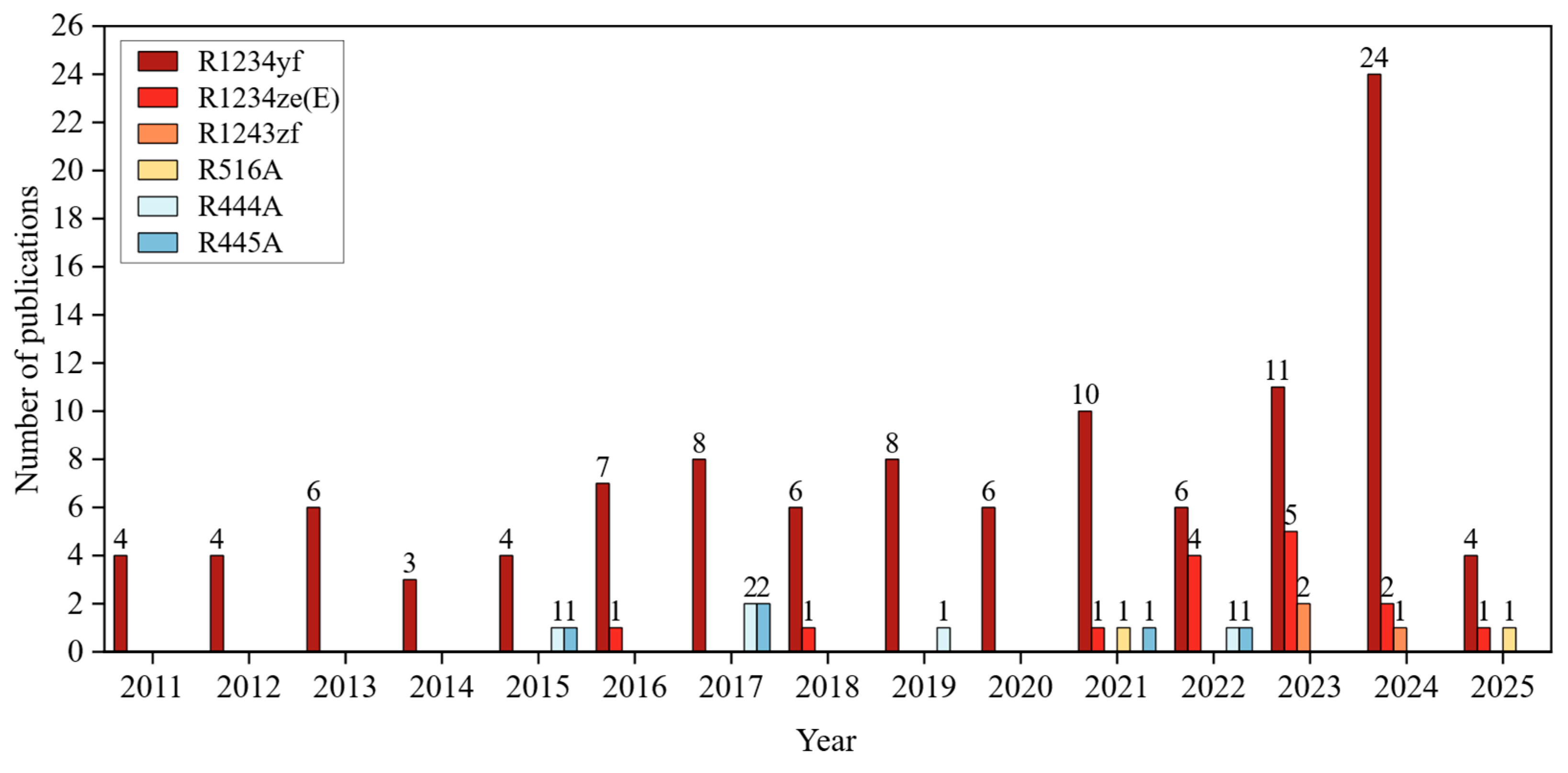
Although the consideration of alternative refrigerants in MAC systems has seen an increase in recent years, in addition to the restriction of the search for refrigerants with a GWP < 150, another limitation to implementation is the thermal and energy performance of these fluids. Such performance depends significantly on thermophysical properties, which are very important in the search for refrigerants that are options for the replacement of R134a [13]. Among the properties that can improve the coefficient of performance (COP) are high values of latent heat of vaporization, thermal conductivity, and specific heat; also, low values of vapor pressure, liquid density, and liquid viscosity can improve this performance parameter [23,24]. Therefore, pure HFO refrigerants R1234yf, R1234ze(E), and R1243zf, as well as refrigerant blends (HFC/HFO) R516A, R444A, and R445A, have been considered in this work to evaluate their performance in different cycle configurations for MAC systems. Figure 1 shows the number of publications since 2011 related to these refrigerants that have been assessed in MAC systems.
Likewise, the MAC systems of conventional, hybrid, and electric vehicles primarily operate with the basic vapor compression refrigeration cycle, which consists mainly of a compressor, a condenser, an expansion valve, an evaporator, and a filter. However, in conventional vehicles, it has been shown that this type of system accounts for a consumption of between 12% and 17% of the total engine energy [25]; this indirectly implies a negative environmental impact due to the amount of CO2 emissions represented by this energy consumption, and high fuel consumption costs.
Electromobility, a concept used to define the movement of vehicles using electricity instead of fossil fuels, has led to an increase in the use of hybrid and electric vehicles towards the objectives announced by the International Energy Agency in search of neutrality in greenhouse gas emissions by 2050, for which it establishes that the sale of conventional vehicles with internal combustion engines will be significantly reduced as of 2035 [26]. However, electric vehicles that do not generate indirect pollution through fuel demand by operating the air conditioning system allocate approximately 77% of the battery’s energy capacity to operating the MAC system [27]; this has an impact on one of the most essential aspects of both hybrid and electric vehicles—the need to reduce the consumption of the energy available in their batteries to increase transport capacity sustainably for a longer period of time.
Therefore, some researchers have focused their resources on improving the performance of the basic vapor compression cycle of MAC systems to reduce the energy consumption required for their operation. Among the alternatives is the inclusion of an internal heat exchanger (IHX) in the vapor compression cycle; this exchanger produces a reheating and subcooling effect, the latter being an option to improve the cooling capacity of the cycle. Several studies have shown that the inclusion of an IHX can increase the coefficient of performance, representing a reduction in the energy consumption of MAC systems [28,29,30,31,32].
Another alternative to reduce the energy consumption represented by MAC systems in a vehicle is the replacement of the expansion devices commonly used in the basic vapor compression cycle. The most widely used expansion elements are the short tube and the expansion valve. However, these components have proven to be a significant factor in increasing the irreversibility of the cycle, thus generating a decrease in system efficiency. In this sense, the inclusion of an ejector as an expander element within the MAC can reduce the irreversibility of the expansion process and lower the pressure ratio of the compressor, thereby improving the system’s efficiency. Some investigations on the use of an ejector in MAC systems have found an improvement in the performance of the refrigeration cycle compared to the basic vapor compression cycle. Additionally, they have shown a reduction in the energy demand of the vehicle [33,34,35,36,37,38,39].
According to the literature and considering the constant evolution of refrigerants, this paper performs an energy, exergy, and exergoeconomic analysis of alternative configurations to the basic cycle in MAC systems commonly used in conventional, hybrid, and electric vehicles, utilizing low- and ultra-low-GWP refrigerants classified as A2L for the ASHRAE Standard, which are envisioned as replacements for the current R134a. This aims to define, from an energy perspective, the conditions under which refrigerants can be considered direct replacement alternatives and under what configurations of MAC systems they can be competitive with R134a. In addition, the exergy analysis seeks to identify which components and refrigerants represent a greater exergy destruction, which affects the system’s performance. Similarly, through the exergoeconomic evaluation, the economic impact involving cycle configurations and alternative refrigerants compared to the traditional basic cycle of MAC systems operating with R134a is evaluated. Finally, through environmental analysis using the TEWI as a unit of measurement, the amount of CO2 emissions associated with the employability of each refrigerant considered under the evaluated cycle configurations is determined. This analysis reports the pollution footprint for the operating cycle of the proposed alternatives.

2. Materials and Methods

2.1. Cycle Configurations

Automotive air conditioning systems have evolved. In this sense, some configurations promote energy savings compared to the conventional basic cycle used by motor vehicles. Therefore, it is interesting to evaluate those configurations that promise fuel savings. Thus, the configurations analyzed in this work are the following:
  • Basic cycle (BC);
  • Cycle with internal heat exchanger and thermostatic expansion valve (IHXC + TEV);
  • Cycle with internal heat exchanger and short tube (IHXC + ST);
  • Cycle with ejector (EC);
  • Cycle with ejector and internal heat exchanger (EC + IHX).
The choice of cycle configurations was based mainly on recent research, which shows that these types of configurations can be highly viable for mobile air conditioning systems. Furthermore, these alternatives do not require the addition of a large number of components, except the ejector and IHX cycle, compared, for example, to cascade systems or transcritical CO2 systems, which may involve adding extra weight or more robust materials required for such systems, increasing costs and generating higher vehicle energy consumption, and possibly offsetting the benefits of the improved alternative cycle configuration.
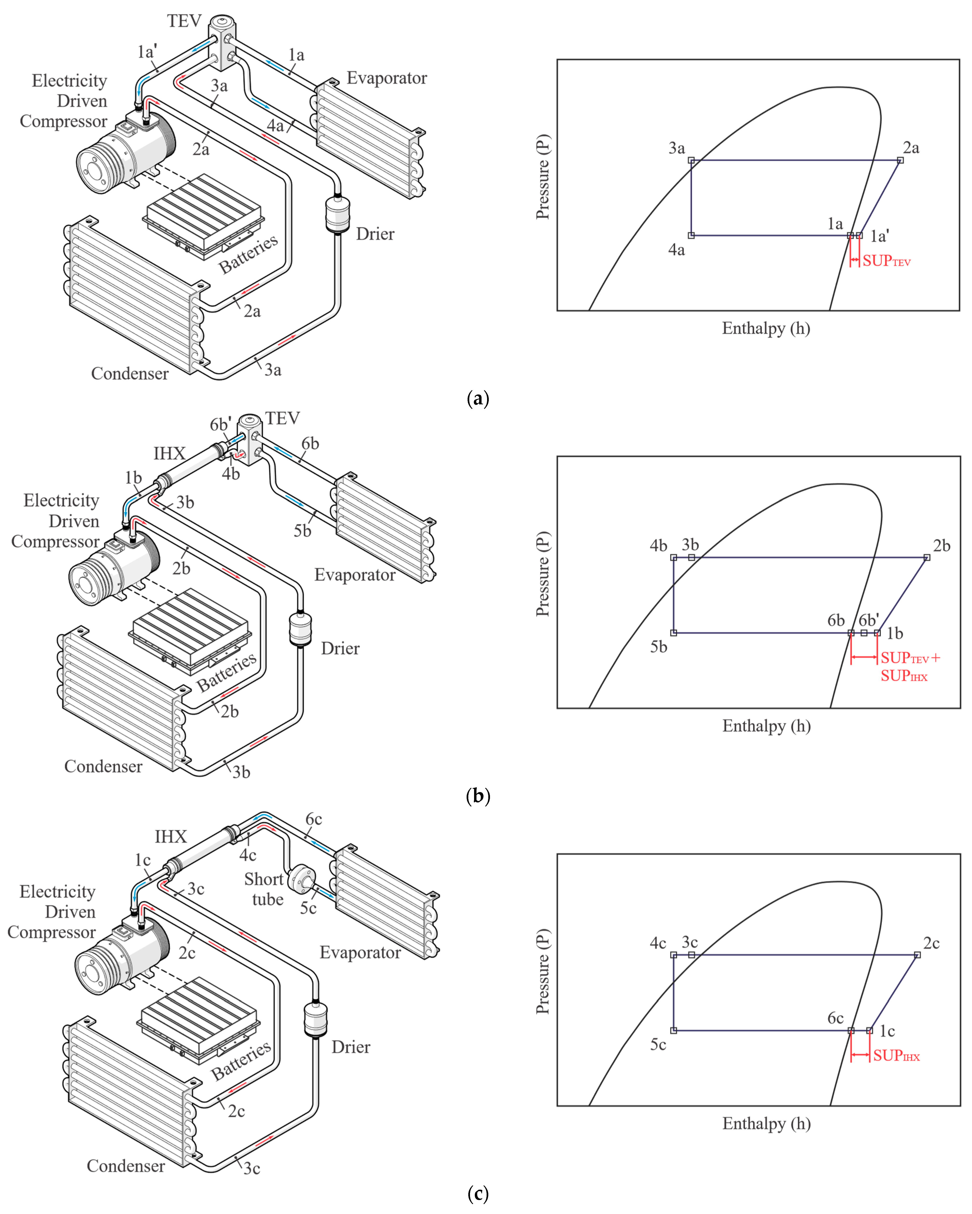
Figure 2 illustrates the schematics and P-h diagrams of the first three configurations, which represent the basic conventional vapor compression cycle used in MAC systems, as well as two alternatives for this cycle that incorporate an internal heat exchanger. In all cases, the scheme is accompanied by the P-h diagram that describes the thermodynamic states through which the refrigerant passes during its path through the different components of the cycle.
The description of the configurations is given below.

2.1.1. Basic Cycle (BC)

In the present work, this configuration serves as a reference for comparing all the proposed alternatives. Currently, the basic vapor compression cycle is the most common in MAC systems and consists of four main components: compressor, condenser, thermostatic expansion valve, filter-drier, and evaporator. Considering the real operation of the cycle, the P-h diagram in Figure 2a shows the thermodynamic states of the refrigerant. The fluid at the outlet of the evaporator is a saturated vapor that undergoes superheating provided by the thermostatic expansion valve (1a). This fluid enters the compressor, which is responsible for increasing its temperature and pressure to generate superheated steam (2a), which then enters the condenser, where it releases heat to the environment, reaching its output as a saturated liquid (3a). This liquid passes through the expansion valve, where a pressure drop in the refrigerant occurs, reducing its temperature and pressure, resulting in a fluid output of a certain quality (4a). Finally, in the evaporator, the change in state of the refrigerant is produced by the absorption of heat removed from the space to be cooled, leaving a saturated vapor (1a), thus completing the cycle.

2.1.2. Cycle with IHX and Thermostatic Expansion Valve (IHXC + TEV)

The purpose of including an internal heat exchanger in the basic cycle is to enhance the refrigerant effect in the evaporator, thereby increasing cooling capacity. As shown in Figure 2b, this component produces an increase in refrigerant superheating at the evaporator outlet (6b′–1b) and an increase in subcooling at the condenser outlet (3b–4b). This subcooling contributes to a decrease in the quality of the refrigerant at the outlet of the expansion valve (5b), which increases the enthalpy difference in the evaporator (5b–6b) and enhances the cooling effect of the cycle. The process through the compressor, condenser, and evaporator is similar to the basic cycle. However, the main differences are the reheating and subcooling stages.

2.1.3. Cycle with IHX and Short Tube (IHXC + ST)

The use of a short tube as an expansion device in the refrigeration cycle could reduce investment and installation costs compared to the basic cycle operating with a thermostatic expansion valve. Figure 2c shows the schematic of this configuration, and the process described in the P-h diagram is similar to the basic refrigeration cycle. However, the main difference lies at the outlet of the condenser (3c), where the refrigerant in saturated liquid state enters the short tube, in which the difference in diameters between the tubes connecting the inlet and outlet of this component induces the expansion of the refrigerant, thus decreasing its pressure and temperature and increasing its quality at the outlet (4c). Additionally, the short tube prevents overheating at the evaporator outlet.
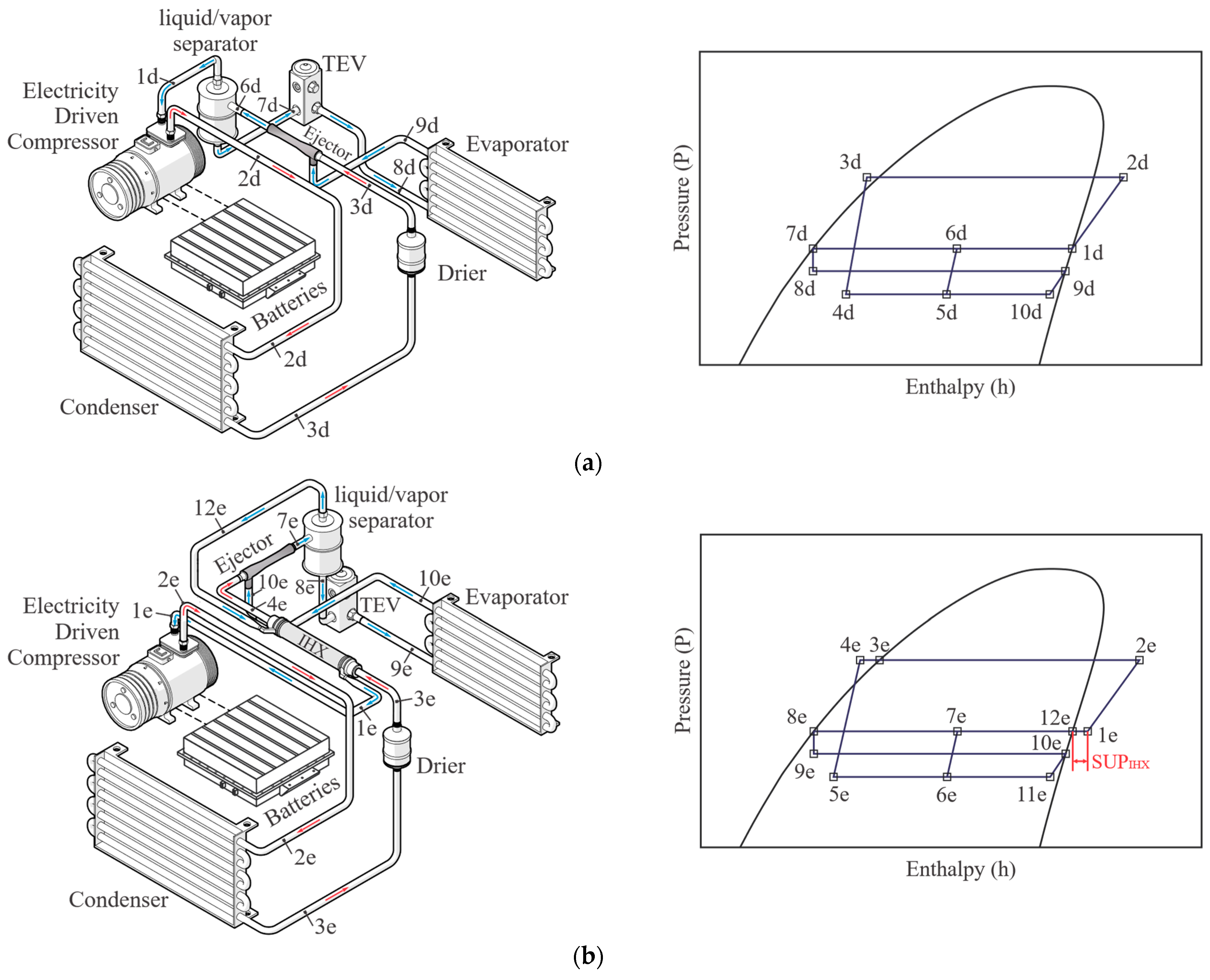
Another alternative to enhance the thermodynamic performance of the basic vapor compression cycle is to replace the conventional expansion device with an ejector, which can reduce irreversible losses during the expansion stage and improve the cycle’s performance. In this sense, Figure 3a,b shows the scheme and P-h diagram of the configurations with an ejector and the alternative of incorporating an internal heat exchanger in the cycle with an ejector.

2.1.4. Ejector Cycle (EC)

Replacing the traditional expansion device in MAC systems with an ejector can help recover the expansion work lost at this stage and reduce compressor energy consumption. Figure 3a represents the schematic and P-h diagram for the (EC) configuration, and the process that takes place in this cycle is described below: the refrigerant leaving the liquid–vapor separator as saturated vapor (1d) enters the compressor, which increases the refrigerant pressure to a superheated state (2d). The refrigerant then passes through the condenser and exits as a saturated liquid (3d) to enter the ejector motive nozzle, where its pressure is significantly reduced (4d) until it reaches the evaporating pressure. Likewise, the fraction of refrigerant in the saturated liquid state leaving the separator (7d) enters an expansion valve that reduces the pressure to the evaporation condition to leave as a two-phase mixture (8d). It then enters the evaporator, where the mixture becomes a saturated vapor at the outlet (9d). Subsequently, it passes into the ejector suction nozzle (10d), which represents the lowest pressure point in the cycle. At this stage, the primary flow coming from the condenser and the secondary flow coming from the evaporator are mixed at constant pressure in the ejector (5d). This mixture enters the diffuser, which is responsible for increasing the pressure and decreasing the fluid velocity (6d). Finally, the refrigerant at the outlet of the diffuser enters the separator, where the separation of liquid and vapor occurs, starting the cycle again.

2.1.5. Ejector Cycle with IHX (EC + IHX)

Figure 3b shows the schematic of the cycle with an ejector and IHX. The internal heat exchanger is located between the condenser outlet and the compressor inlet. The process that takes place is similar to the ejector cycle. However, the inclusion of the IHX represents some variations. Initially, the saturated vapor leaving the vapor–liquid separator (12e) enters the IHX, where it undergoes superheating through energy exchange with the hot stream exiting the condenser (3e). The vapor with a higher temperature (1e) enters the compressor, which increases its temperature and pressure up to the discharge (2e). This superheated vapor enters the condenser, releasing heat to reach a saturated liquid state (3e). Here, the energy transfer process of this hot stream occurs with the low-temperature vapor leaving the separator (12e). Subcooling occurs at the outlet of the hot stream entering the IHX (4e). The subcooled liquid refrigerant then goes directly to the ejector motive nozzle, where its pressure is reduced and the velocity increases (5e). Theoretically, the IHX in this cycle also promotes the increased cooling capacity of the cycle.

2.2. Input Parameters

2.2.1. Factors Considered for Ejector Cycle Modeling

According to the literature, the analysis of ejectors in a refrigeration cycle is based on two main models: the constant area and constant pressure models, with the latter showing better performance of the ejector in the cycle [40,41,42,43]. Therefore, the analysis of the EC and EC + IHX configurations is developed based on this model. For the study of the ejector, the principles of conservation of mass, momentum, and energy are applied in each section of this component, following the methodology developed by [44].
Table 2 shows the main characteristic equations for evaluating each of the ejector sections. Two subscripts are included to indicate that each of the thermodynamic states in the equations contained in Table 2 may belong to the cycle with an ejector or the cycle with an ejector and IHX.
In general, some considerations were raised to simplify the theoretical model of the cycle, which are:
  • The analysis is based on steady state conditions;
  • Pressure drops occurring in the energy exchange components and through the piping lines are neglected;
  • The states at the outlet of the evaporator and condenser are saturated;
  • The throttling process in the expansion valve is isenthalpic;
  • Friction losses occurring due to the flow within the ejector components are considered in the form of efficiencies;
  • The efficiencies of the ejector components are constant.

2.2.2. Operating Conditions for All Cycle Configurations

In the literature, several theoretical and experimental works have evaluated operating conditions for both evaporation and condensation in the basic cycle of MAC systems [14,28,30,31,45,46,47,48,49,50,51,52]. Table 3 presents the general operating conditions considered for the cycle configurations described in the previous sections.

2.2.3. Validation of the Model Used in the Cycle with Ejector

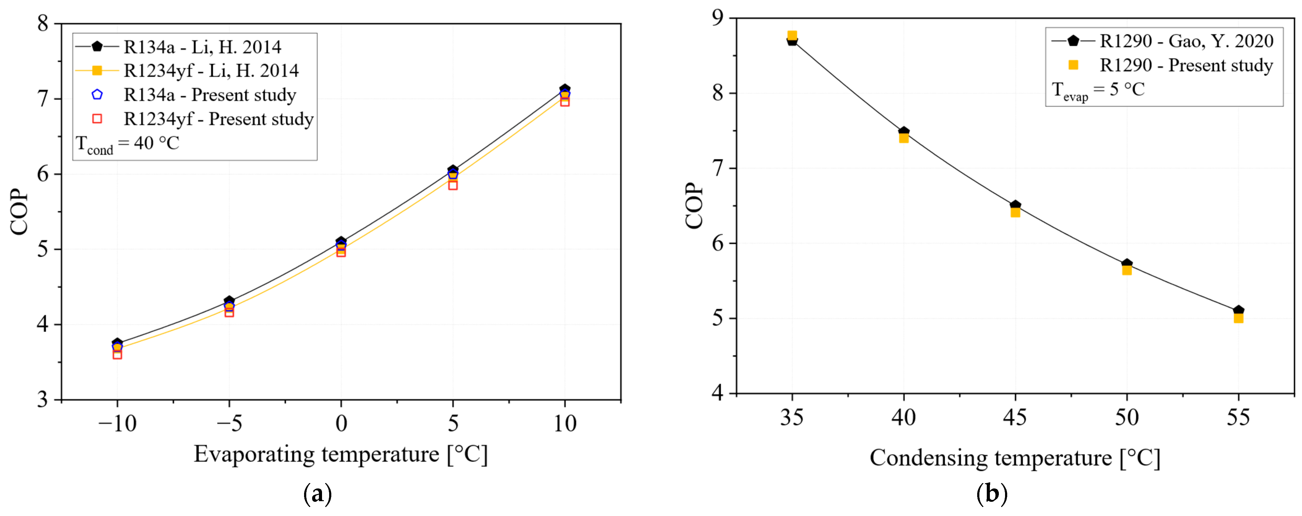
The model used to evaluate the cycle with the ejector is validated. In this case, the model results are compared with two articles using comparative analysis under the same operating conditions and with specific refrigerants [40,55]. As shown in Figure 4, the model used fits well with the results of the references consulted. In both cases, the adjustment error does not exceed 2%.

2.2.4. Sensitivity Analysis for Cycles with Ejector

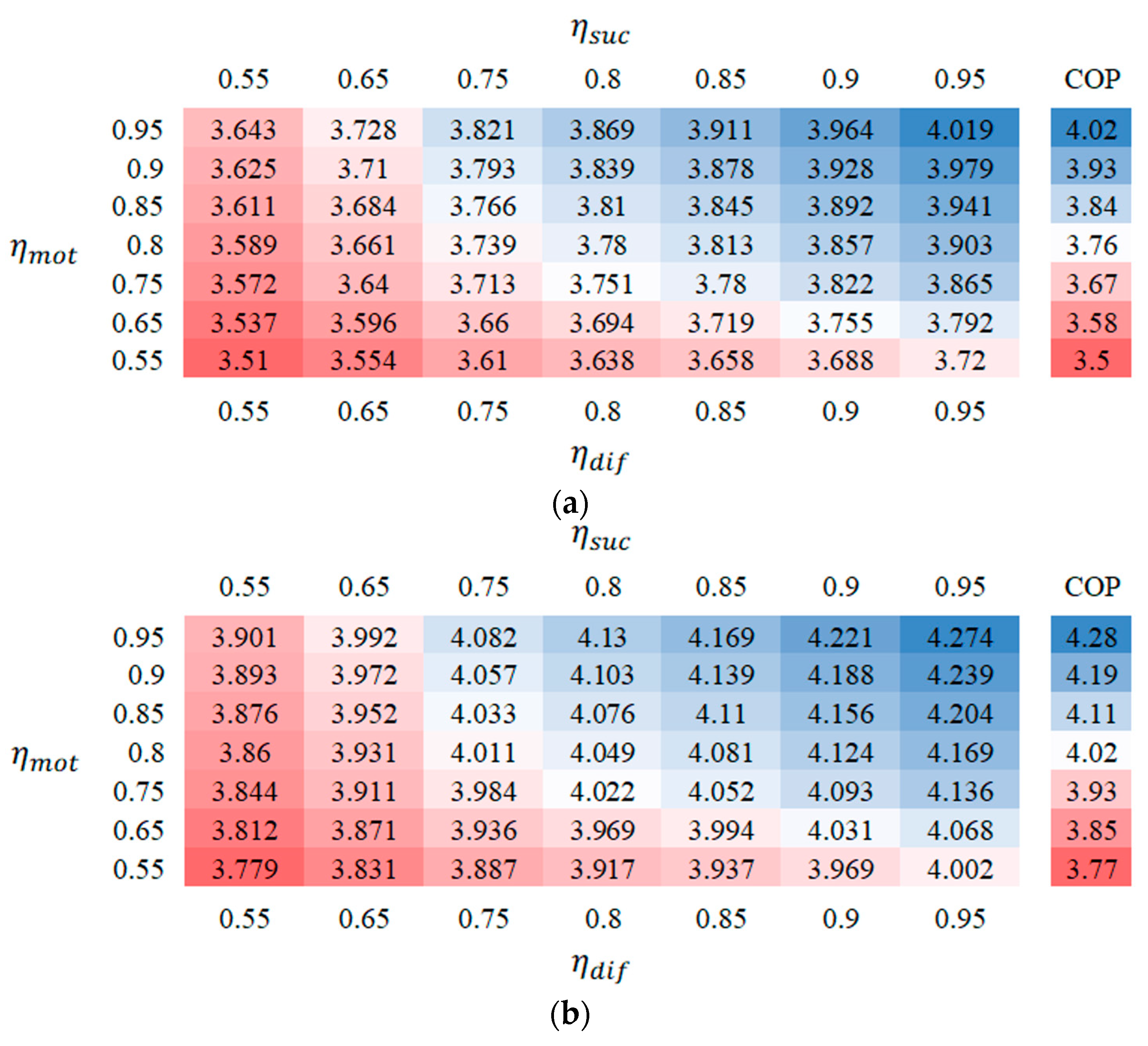
The sensitivity analysis considers the variation in the efficiencies of the ejector sections. In this sense, a variation is made in the efficiencies of the ejector sections; in this case: the motive nozzle, the suction nozzle, and the diffuser. The response variable analyzed is the COP. In this case, as evidenced in the literature, the motive nozzle has a significant influence on the performance of the ejector, since it is the device responsible for generating the expansion of the refrigerant that enters the ejector at high pressure from the condenser. As shown in Figure 5, there is significant variation in the COP at an efficiency of 0.55. However, the variation with respect to the values used in the present study, which has been investigated mainly in different publications, is close to 7%. Although there is a significant lack of specific studies addressing the experimental use of an ejector in mobile air conditioning systems, the parameterization of the ejector component efficiencies using isentropic efficiencies between 0.8 and 0.9 has been included in the modeling of ejectors in refrigeration and air conditioning systems.
Based on the above considerations, a mathematical model is developed in Python® (Version 3.13.0 2024), connected to the REFPROP property base [61], through which the performance of each cycle configuration and refrigerant under study is simulated for all operating conditions, as described in the following section.

2.3. Low-GWP Alternative Refrigerants

According to the literature, pure refrigerants R1234yf, R1234ze(E), R1243zf, and refrigerant blends R516A, R444A, R445A can meet the GWP restrictions imposed on MAC systems. Therefore, this section presents the characteristics of environmentally friendly refrigerants for the phase-out of R134a. Table 4 compares the main thermophysical properties of alternative refrigerants with those of R134a.
Consequently, from a long-term perspective, potential refrigerants must meet several characteristics such as being safe and having low GWP, optional thermal properties, and competitive energy efficiencies. However, it has been challenging to find these conditions simultaneously. Therefore, this study aims to identify refrigerants with GWP < 150 that are slightly flammable (A2L in ASHRAE class), are non-toxic in mobile air conditioning systems, and can achieve or improve the energy efficiency of R134a. In this sense, the performance of these alternative refrigerants is a function of their thermophysical properties. For example, as shown in Table 4, R445A has a saturation pressure 46.9% higher than that of R134a under the same operating conditions. Higher evaporator pressure is associated with an increase in the refrigerant’s effect and cooling capacity. Similarly, this property can contribute to the performance of R516A, as the saturation pressure is 8.13% higher than that of R134a.
Similarly, the liquid density directly influences the refrigerant mass charge requirement in the system, which is achieved when the refrigerant has a low liquid density. For the temperature condition in Table 4, all the refrigerants represent a lower charge requirement in the system compared to R134a, with R516A offering the most significant reduction in this aspect. Low refrigerant charges translate into lower refrigerant costs, smaller compressors, and reduced weight associated with the MAC system.
Likewise, a high thermal conductivity of the liquid helps improve heat transfer, allowing the use of smaller or more compact heat exchangers, which results in a lower initial investment cost. It also results in a reduction in overall vehicle space and weight, thus reducing fuel consumption. For all alternative refrigerants, the thermal conductivity of the liquid is lower than that of R134a, with the difference being smaller for R1234ze(E) and R445A. However, the vapor thermal conductivity of all refrigerants is the same or higher than that of R134a; this contributes to higher degrees of superheating, improved heat dissipation within the condenser, and greater energy transfer for cycle configurations with IHX.

2.4. Equations for Energy Analysis

For the development of this analysis, two important parameters are considered: the volumetric refrigeration capacity in the evaporator ( V R C ) and the coefficient of performance ( C O P ).
Refrigerant effect,
q e v a p = h o u t ; e v a p h i n ; e v a p
The V R C is defined as the refrigeration capacity per unit volume at the outlet of the evaporator and is determined by the ratio of the refrigerant effect obtained in the evaporator to the specific volume at the suction of the compressor, as reflected in Equation (2).
V R C = q e v a p v i n ; c o m p
Compressor specific work,
w c o m p = h o u t ; c o m p h i n ; c o m p
For analyzing the specific work required in the compressor, it is necessary to determine the isentropic efficiency, which is a function of the pressure ratio in the compressor. In this case, the empirical expression reflected in Equation (4) [45] is used, which was developed for a MAC system using R134a as the refrigerant and for conditions similar to those shown in Table 3. Similarly, this equation has been employed for the analysis of MAC systems, with R134a [62], R1234yf [63], R450A, R1234yf, R513A, R516A, R152A, R1234ze(E) [64], and R410A [65]. In this sense, Equation (4) has been used for low–medium evaporating temperatures ranging from −5 °C to 15 °C and for condensing temperatures ranging from 35 °C to 60 °C.
η i s e = 0.9343 0.04478 ( p d i s p s u c )
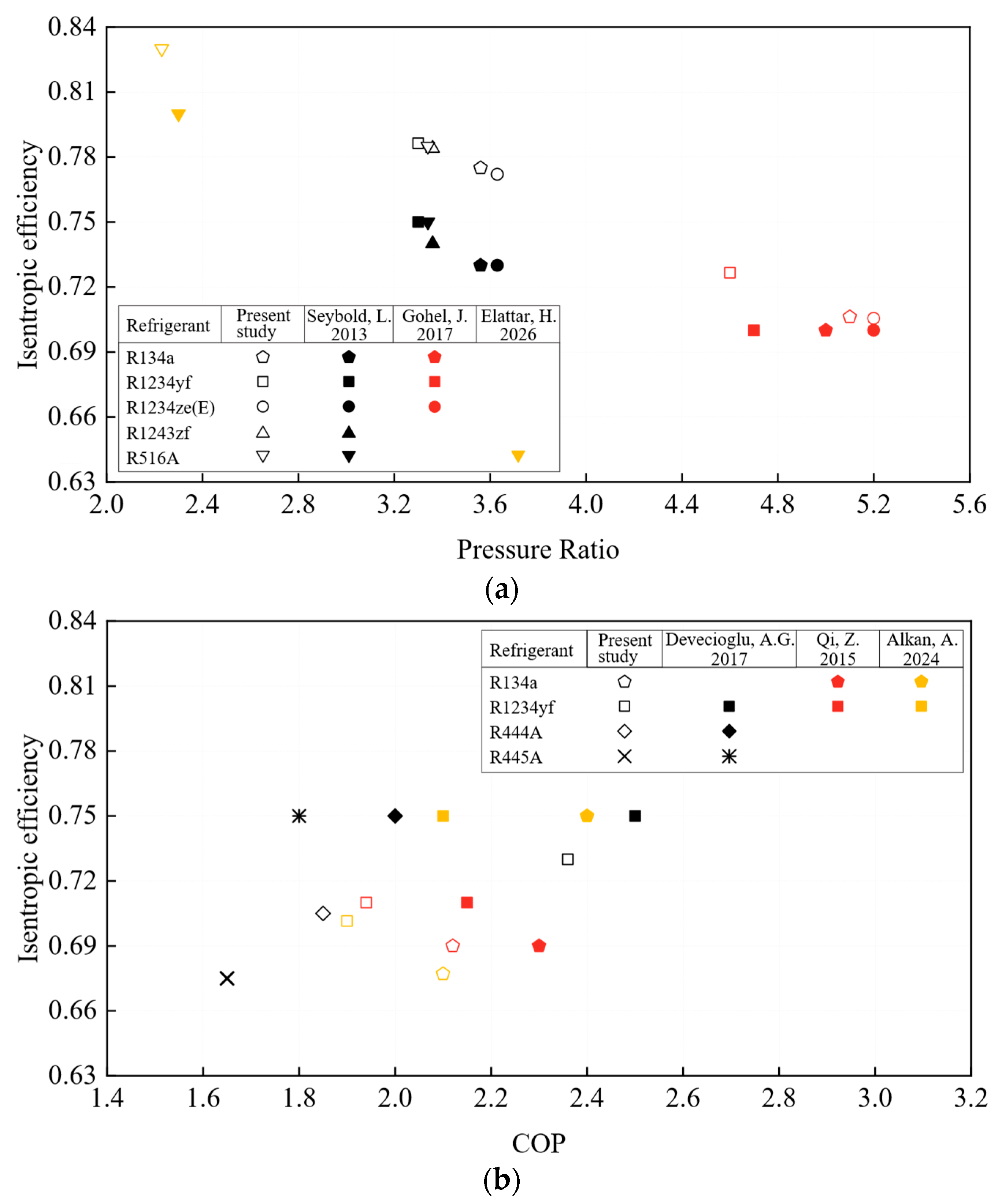
To verify the validity of Equation (4), comparisons are made with various references on mobile air conditioning systems, including analyses of isentropic efficiency and models evaluated against a specific isentropic efficiency. In this regard, Table 5 shows the main analysis conditions used to compare the isentropic efficiency.
Figure 6 shows that the correlation used to model refrigerant isentropic efficiency does not lead to oversizing of the main performance parameters analyzed. Although there is a margin of error for the isentropic efficiency equation, this is due to the limited information available on specific correlations for each refrigerant, which is even more pronounced for refrigerants such as R1243zf, R516A, R444A, and R445A, as there are very few references on the use of these refrigerants in mobile air conditioning systems.
The COP evaluation is determined by Equation (5), which reflects the refrigerant effect in the evaporator obtained in the cycle for a specific work requirement in the compression stage.
C O P = q e v a p w c o m p
For cycle configurations with an internal heat exchanger, the effectiveness of this equipment is a parameter that influences the cycle performance. Therefore, this effectiveness is defined as a function of the temperatures of the flow streams at the inlet and outlet of the IHX.
ϵ I H X = ( T o u t ; C T i n ; C ) ( T i n ; H T i n ; C )

2.5. Equations for Exergy Analysis

The exergy analysis aims to detect which component of each cycle configuration has the most significant impact on system performance. The equations for determining the exergy destruction in each piece of equipment are described below.
Total exergy encompasses four primary factors: physical, chemical, kinetic, and potential exergy [70].
E ˙ T O T = E ˙ p h y + E ˙ c h e + E ˙ k i n + E ˙ p o t
Since there are no high-velocity or level differentials in the systems to be analyzed, and the fluid does not experience chemical changes during each stage of the process, the exergy calculation is simplified to Equation (8).
E ˙ T O T = E ˙ p h y
Physical exergy considers the difference in enthalpy and entropy that exists between each thermodynamic state of a particular cycle configuration concerning a reference state, the latter corresponding to a temperature T o   =   25   ° C and a pressure P o   =   101.3   k P a .
E ˙ p h y = E ˙ = m ˙ ˙ [ ( h h o ) T o ( s s o ) ]
For each component of the cycle, an analysis is performed based on the first and second laws of thermodynamics. In this sense, Equation (10) generally denotes the exergy balance for any control volume, which refers to the exergy destruction that takes place in each component.
E ˙ D ,   k = ( 1 T o T ) Q ˙ W ˙ i n + i n E ˙ o u t E ˙
This exergy destruction in the cycle represents the loss of quality in the energy supplied to the system, as an energy balance cannot account for these losses. Furthermore, the quantification of exergy destruction provides information on the possibility of improving the cycle from a thermodynamic perspective. The total exergy destroyed is the sum of the irreversible losses of each component in the analyzed cycle configuration, calculated using Equation (11). Here, the subscript k refers to a specific component.
E ˙ D ; T O T = E ˙ D ; k
Exergy efficiency relates to the total exergy destruction of the cycle, which results from the sum of the irreversibilities of all cycle components and the energy consumption of the compressor. From the exergy efficiency, it is possible to determine whether the cycle configuration induces significant irreversible losses, considering the amount of power supplied to the cycle. Equation (12) allows for the calculation of exergy efficiency.
η e x = 1 E ˙ D ; T O T W ˙ c o m p

2.6. Equations for Exergoeconomic Analysis

This analysis is also known as thermoeconomic evaluation and relates each exergy stream to the costs associated with the operation of each component within the cycle. Therefore, Equation (13) allows for the evaluation of the cost balance based on the exergy of the flow streams involved in each component.
C ˙ P ; K = C ˙ F ; K + Z ˙ K
Here, C ˙ F ; K and C ˙ P ; K represent the cost ratios associated with the fuel and product in component ‘k’, and these costs are related to the unit cost of each exergy stream involved in the component ( c ˙ F ; K and c ˙ P ; K ).
C ˙ F ; K = c ˙ F ; K × E ˙ F ; K
C ˙ P ; K = c ˙ P ; K × E ˙ P ; K
Likewise, Z ˙ K is the total levelized cost for each component, including investment costs ( I C ) and operation and maintenance costs ( O M ).
Z ˙ K = Z ˙ K I C + Z ˙ K O M
To evaluate the total levelized cost ratio, it is necessary to introduce a capital recovery factor, which considers the interest rate and the lifetime of the equipment, as reflected in Table 6.
C R F = i r ( i r + 1 ) N ( i r + 1 ) N 1
Thus, the costs related to capital investment and operation/maintenance are determined by Equations (18) and (19), respectively. Table 6 shows the operation and maintenance cost factor.
Z ˙ K C I = C R F t o p e × Z K
Z ˙ K O M = Z ˙ K C I × φ
The investment cost ( Z k ) of each heat exchanger is determined as a function of its working capacity and heat transfer; therefore, the size of each component, specifically the evaporator, condenser, and IHX, has a significant impact on its investment cost. To calculate the areas of the evaporator and condenser, a finned geometry was selected for these heat exchangers, and they operate in cross-flow with air. In the case of the IHX, its structure is a tube-in-tube exchanger. The equations used to determine these areas are shown in Appendix A. Similarly, the mass flow rate, pressure ratio, and efficiencies influence the investment costs of components such as the compressor and expansion devices. Table 7 shows the equations used to calculate the investment costs of each component.
Investment costs must be updated to their present value; for this purpose, Equation (20) is used.
Z n e w = Z r e f e ( I n e w I r e f e )
Here, I n e w and I r e f e are the Marshall and Swift indexes [77]. The exergoeconomic evaluation of each refrigerant and cycle configuration is analyzed under the following parameters:
The total cost ratio associated with exergy destruction:
C ˙ D ; T O T = c ˙ F ; T O T × E ˙ D ; T O T
The total cost ratio is evaluated as a function of energy costs and the total levelized investment cost.
C ˙ T O T = C ˙ D ; T O T + Z ˙ T O T
Another important evaluation parameter is the exergoeconomic factor, which relates to the contribution of investment costs and exergy destruction costs in each component.
f K = Z ˙ K Z ˙ K + ( c F ; K × E ˙ D ; K )
Table 8 describes the equations used for the exergy and cost analysis, which allow the study of the exergoeconomic performance of the different cycle configurations analyzed.

3. Results and Discussion

The results are analyzed based on the range of evaporating temperatures considered, from 0 °C to 16 °C with steps of 4 °C, and for two condensing conditions of 45 °C and 55 °C, evaluating five cycle configurations. The main parameters for assessing the energy, exergy, and exergoeconomic performance of the alternative refrigerants to R134a considered in this work are presented below.

3.1. Energy Analysis

Based on the analysis of each cycle configuration for all alternative refrigerants, with refrigerant R134a and the basic cycle with a thermostatic expansion valve serving as a reference for comparison, the evaluation of the volumetric refrigeration capacity (VRC) and the coefficient of performance (COP) is presented.

3.1.1. Volumetric Refrigeration Capacity (VRC)

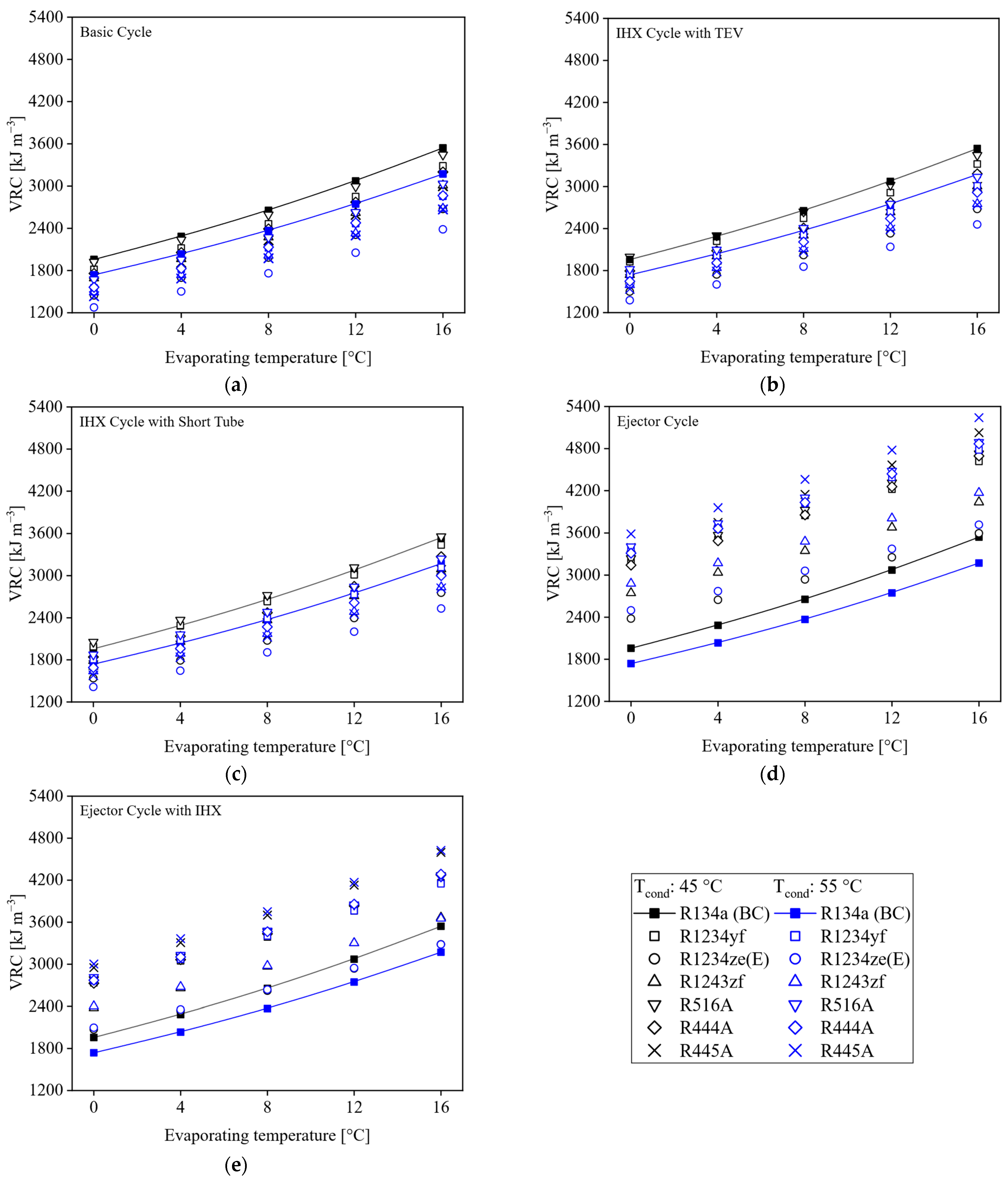
The VRC measures the cooling capacity per unit volume of a refrigerant. For low values of this parameter, the inclusion of a compressor with a greater capacity is required. With similar values of the VRC, no changes are necessary in the engine component of the MAC system, allowing for the direct replacement of R134a with the alternative refrigerant. Thus, Figure 7 presents the behavior of the VRC for the refrigerants evaluated, operating under the five cycle configurations. In each of the figures, lines are used to denote the reference, indicating the performance of R134a under the basic cycle of a MAC system.
Figure 7a shows a comparison of alternative refrigerants with R134a under the basic cycle of a MAC system. For all evaporating temperatures and the two condensing conditions, all alternative refrigerants have a lower VRC. For this cycle configuration, R1234ze(E) has the lowest VRC when varying the evaporating temperature from 0 to 16 °C. Among the causes is its low latent heat of evaporation at a similar operating pressure compared to R134a. In addition, R1234ze(E) has a lower vapor density relative to the suction of the compressor, leading to a decrease in cooling capacity. On the other hand, R516A exhibits similar behavior to R134a in terms of VRC, especially at an evaporating temperature of 0 °C. However, with increasing evaporating temperature, alternative refrigerants have a greater reduction in suction density compared to R134a, leading to a decrease in VRC.
The impact of including an IHX in the basic cycle of MAC systems is shown in Figure 7b, where the VRC of alternative refrigerants is compared with that of R134a. Here, R516A and R1234yf are favored under this configuration, with the VRC of R516A approximately equal to that of R134a. For R1234yf, a considerable approach is observed, with a percentage difference of 5% compared to R134a. This is mainly due to the increase in subcooling involving the IHX within the cycle, which favors the increase in the refrigerant effect in the evaporator; however, because under this configuration the assumed superheating of 5 °C involving the TEV is added to the superheating caused by the IHX, this results in a high suction temperature, leading to an increase in the specific volume and therefore a lower VRC.
On the other hand, the use of a short tube as an expansion element in the MAC system results in zero superheating at the evaporator outlet, which improves the VRC of the alternative refrigerants, as shown in Figure 7c. R516A exceeds the VRC of R134a, with its most significant increase of 3% at the 45 °C condition, and R1234yf can match the RVC of R134a. In addition, at a condensing temperature of 55 °C, the VRC presents an increase under the IHX configuration with short tube, because when the condensing temperature increases, the refrigerant effect inside the evaporator decreases; however, the subcooling proportioned for the IHX improves the refrigerant effect, and the suction temperature is increased only by the superheating generated from the IHX, which means that the specific volume of the alternative refrigerants does not increase at the same rate as the IHX cycle with a TEV.
As described above, the inclusion of an ejector as an expansion device within a MAC system promotes an increase in the refrigerant effect in the evaporator because the refrigerant at the evaporator inlet has a lower vapor quality compared to other cycle configurations. Figure 7d presents the VRC of alternative refrigerants using the cycle with an ejector. Here, a significant increase in the VRC for all refrigerants is observed, with this being higher in all scenarios of evaporation and condensation conditions. In this case, R445A offers a higher VRC. This refrigerant mixture has a higher latent heat than R134a at the same saturation pressure; therefore, since the EC involves a reduction in the amount of vapor at the evaporator inlet, the capacity to absorb energy is significantly increased. Similarly, using R1234ze(E) under this configuration, a higher VRC than R134a is obtained at an evaporating temperature of 0 °C.

3.1.2. Coefficient of Performance (COP)

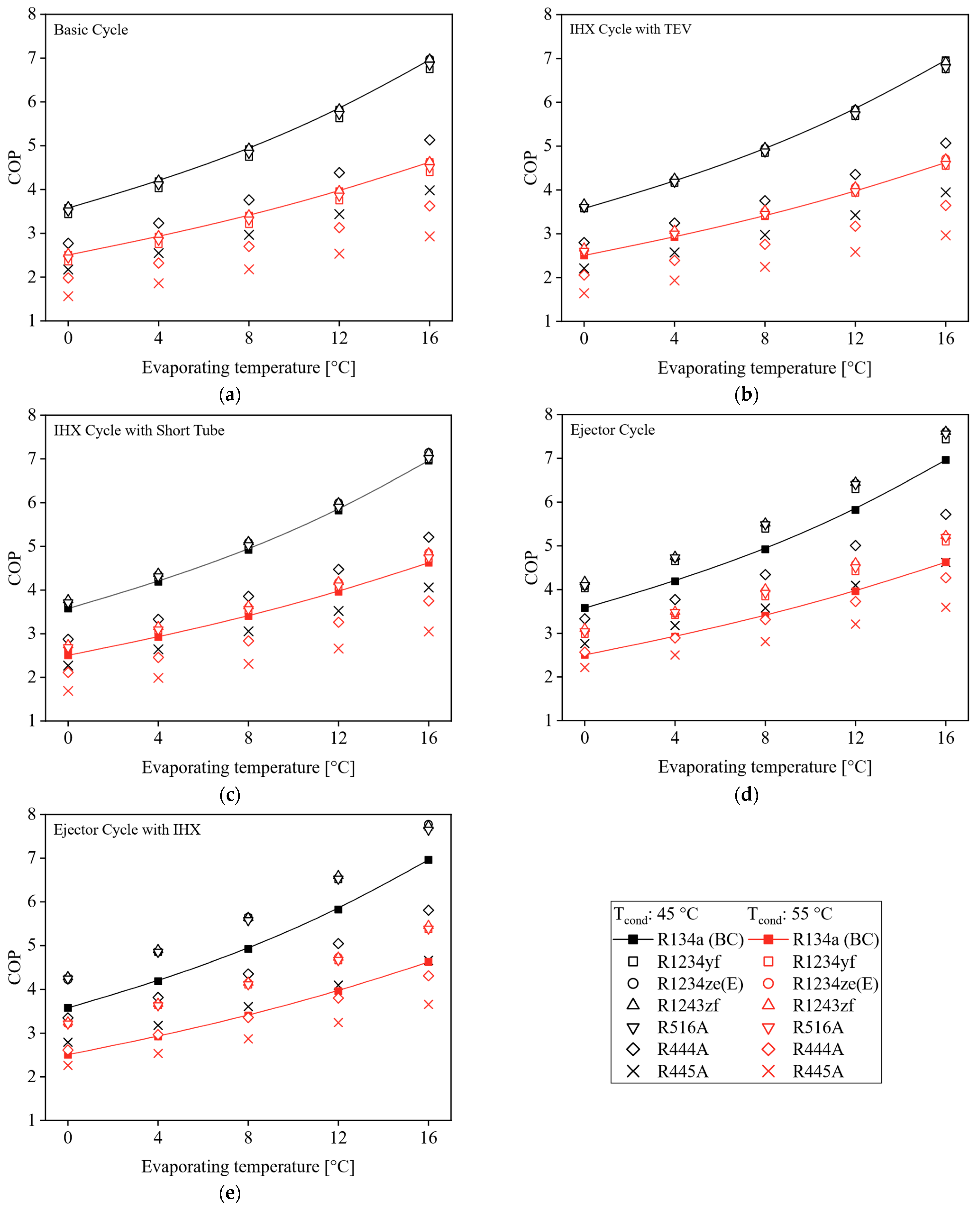
The COP depends on the refrigerant effect achieved in the evaporator and the specific work required by the compressor. In this sense, Figure 8a shows the COPs for all refrigerants operating in the basic cycle compared to R134a. Refrigerants R444A and R445A exhibit lower COPs due to the pressures at which they operate, as their COPs decrease by up to 29.7% and 47.2% at an evaporating temperature of 16 °C. Additionally, refrigerants R1234ze(E), R516A, and R1234yf have COP reductions of 0.37%, 1.4%, and 3.0%, respectively. The refrigerant that offers the highest COP is R1243zf, with a 0.4% increase. Although the cooling effect of these fluids is lower compared to R134a, the lower work requirement allows them to match or even reduce the COP by up to 3%. At a condensing temperature of 55 °C, refrigerants R444A and R445A tend to approach the performance of R134a, as their cooling effect operating at high condensing temperatures does not suffer a significant decrease, unlike the other refrigerants analyzed. However, these zeotropic mixtures exhibit a temperature glide, meaning that, during phase change, they exhibit a significant deficiency in heat transfer. Therefore, when passing through the condenser, a minor efficiency results in higher discharge temperatures, thereby increasing the compressor work requirement, and this is one of the reasons why the R444A and R445A refrigerants have lower COP values.
Similarly, the implementation of an IHX to the basic cycle operating with an expansion valve produces minimal improvements in terms of COP. As shown in Figure 8b, combining the superheating generated by the IHX and that implied by the expansion valve promotes a considerable increase in discharge temperature, leading to an increase in the specific work of the compressor. For all refrigerants compared in this work, the IHXC + TEV cycle configuration implies a slight increase in COP. In this sense, R1234yf reduces its COP difference compared to R134a for the two condensing temperatures of 45 °C and 55 °C.
In turn, the IHX + ST configuration provides an improvement compared to the IHXC + TEV cycle, as shown in Figure 8c, since the absence of superheating due to the short tube results in a reduction in the refrigerant temperature at the compressor suction, thereby reducing the compressor discharge temperature and decreasing the pressure ratio and specific work. The variation in evaporating temperature from 0 °C to 4 °C resulted in refrigerants R1234yf, R1234ze(E), R1243zf, and R516A exceeding the COP of R134a under both condensing conditions. The influence of the IHX in increasing the refrigerant effect contributes to improving the COP of these refrigerants, leading to a reduction in the mass flow required in the evaporator, which is achieved by reducing the specific work needed for the compressor to compress the amount of refrigerant in the suction, resulting in lower power consumption.
Figure 8d shows that the inclusion of an ejector greatly improves the refrigerant effect on the evaporator, as it decreases the vapor quality of the refrigerant at the evaporator inlet, approaching the subcooled liquid region. Moreover, it reduces the pressure ratio of the compressor. Hence, the combination of these two effects produces an increase in the COP of the cycle. In this sense, refrigerants that have a lower pressure ratio have higher performance operating under this cycle configuration, as is the case with R1234ze(E), R1243zf, and R516A. According to Figure 8d, the highest ejector impact is evident for R1234yf, R444A, and R445A. In the case of R1234yf, it improves the refrigerant effect in the evaporator by up to 14%, as this parameter is one of the main disadvantages of R1234yf when it is replaced directly in the basic cycle. Therefore, the cycle with an ejector using this refrigerant can overcome the performance of R134a. For R444A and R445A blends, the ejector cycle makes them competitive with R134a, especially at evaporating temperatures of 0 °C, 4 °C, and 8 °C, where their most significant impact is achieved through the reduction of the pressure ratio, which implies a lower specific work in the compressor.
The ejector cycle combined with an IHX improves the COP of all refrigerants, as shown in Figure 8e. Based on this, R444A exceeds the COP of R134a at an evaporating temperature of 0 °C and a condensing temperature of 55 °C. Furthermore, the EC + IHX cycle implies that the R444A and R445A refrigerants can approximate the performance of R134a; the main reason is the increase in the refrigerant effect due to the ejector and IHX, considering that the evaporation enthalpy of these mixtures is higher than that of R134a under the same evaporation conditions. Additionally, for the cycle with an ejector, it is convenient to increase the entrainment ratio, which enables the cycle with an ejector and an IHX to improve this parameter, thereby enhancing the cycle performance. On the other hand, R1243zf under this configuration exhibits the highest COP of all the refrigerants, with an improvement of up to 11% at the 16 °C evaporation condition, operating at both 45 °C and 55 °C in the condensing stage.

3.2. Exergy Analysis

3.2.1. Destruction of Exergy in the Cycle Components

For each of the analyzed cycle configurations operating with alternative refrigerants, it is important to determine which components have the lowest utilization of the cycle energy, this allows for the determination of whether the additional components of these evaluated configurations involve large irreversibilities, and reveals why this increases or decreases the performance of the alternative cycle configuration relative to the basic cycle of MAC systems.
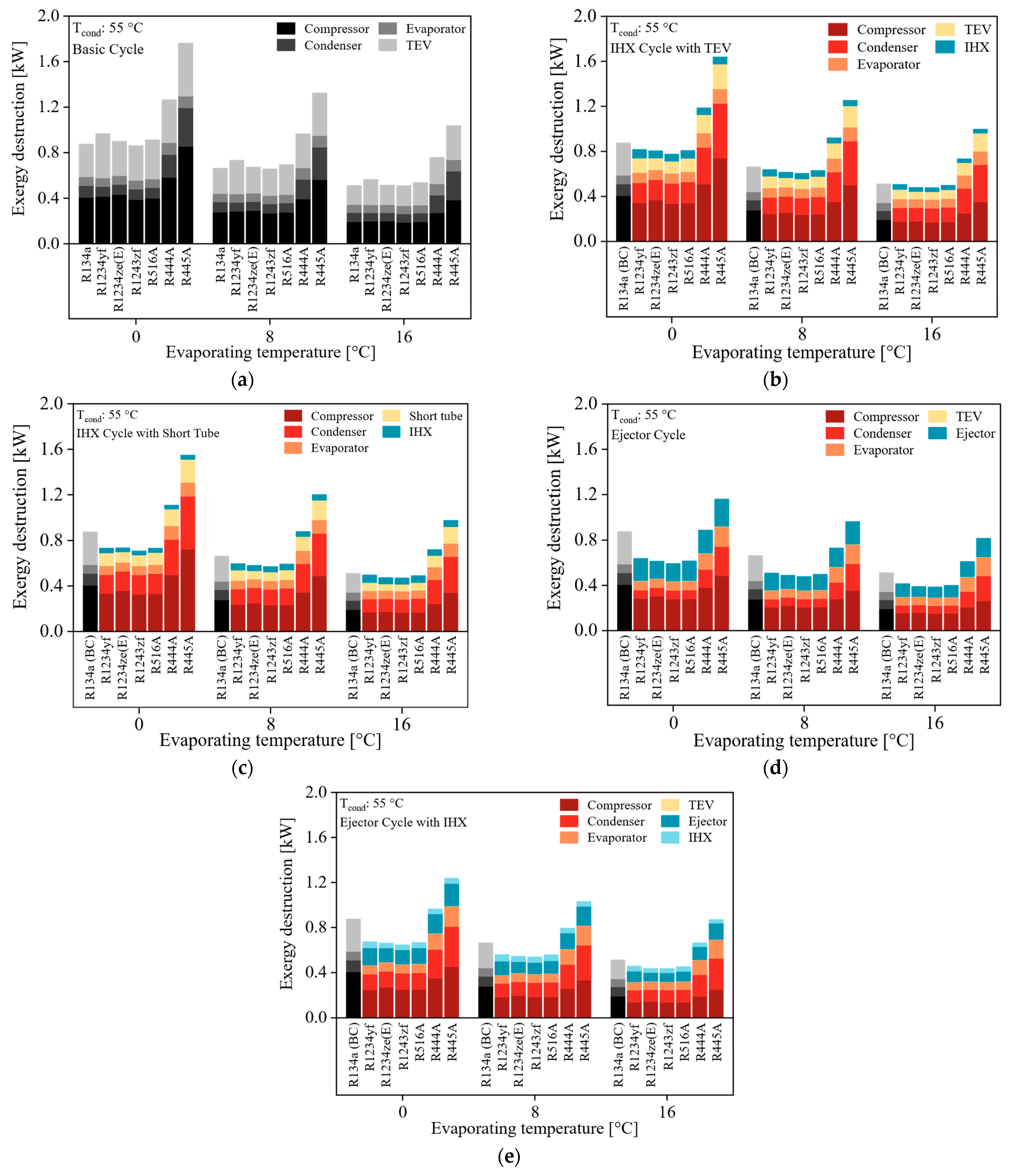
Therefore, Figure 9a illustrates the exergy destruction in each component of the basic cycle. Refrigerants R1234ze(E), R1243zf, and R516a exhibit similar behavior to R134a. However, R1234yf exhibits higher exergy destruction for the three evaporation conditions considered. Here, the difference is the irreversible loss that occurs in the expansion valve, which is related to the high viscosity of R1234yf, resulting in large energy losses during expansion. Similarly, Figure 9a explains the low performance of R444A and R445A, with the latter generating the highest exergy destruction for all evaporation conditions. The greatest influence of irreversibility in R444A and R445A occurs in the compressor and the condenser—in the first element due to its high-pressure ratios, and in the second, the influence of its temperature glide—which, as evidenced in Table 4, affects the evaporation and condensation process inside the heat exchangers.
The expansion device in the basic cycle is a source of irreversibility in the system, as a significant refrigerant pressure drop occurs during the throttling stage, resulting in the waste of energy supplied to the system. The inclusion of an IHX can decrease the exergy destruction of the expansion valve, as seen in Figure 9b. In this sense, R1234yf, R1234ze(E), R1243zf, and R56A decrease the exergy destruction between 43% and 54% for an evaporating temperature of 4 °C, and between 36% and 50% for an evaporating temperature of 16 °C. This is because the subcooling generated by the IHX allows the liquid to reach the TEV inlet at a lower temperature compared to the basic cycle; therefore, during the expansion of the refrigerant, the energy use is higher. Additionally, the IHX introduces a percentage of irreversibility, and it is observed that the condenser experiences an increase compared to the basic cycle with R134a. In this case, the energy dissipation in the condenser is less efficient due to the higher operating conditions concerning the discharge temperature obtained with the inclusion of the IHX.
From an energy perspective, the superheating represented by the expansion valve in the IHXC + TEV configuration has a significant influence, which is responsible for reducing the cycle’s performance. In this case, as shown in Figure 9c, the IHXC + ST configuration provides a significant reduction in the exergy destruction of the cycle, particularly at an evaporating temperature of 4 °C. Under these conditions, refrigerants R1234yf, R516A, R1234ze(E), and R1243zf achieve reductions in exergy destruction of up to 11.4%, 11.9%, 13.1%, and 14.7%, in that order. Zero superheating, resulting from the short tube in this cycle configuration, decreases exergy destruction compared to the IHXC + TEV cycle. Thus, refrigerants R1234yf, R1234ze(E), R1243zf, and R516A reduce the total irreversibility between 45.0% and 60.0% because of a lower temperature and pressure discharges, which results in a lower pressure drop in the short tube, thus reducing the wasted energy in the expansion process.
On the other hand, the cycle with an ejector reduces the total exergy destruction represented by the basic cycle with R134a. In this sense, as shown in Figure 9d, total exergy destruction reductions of 22.9%, 24.9%, 25.1%, and 26.7% are observed for R1234yf, R516A, R1234ze(E), and R1243zf, correspondingly. Another important aspect of the ejector’s inclusion is the reduction in the irreversibility of the compressor, as shown in Figure 9d. The pressure recovery involving the ejector increases the suction pressure, thereby improving the operating conditions of the compressor and decreasing the exergy destruction of this component.
Similarly, Figure 9e shows the exergy destruction of the components of the EC + IHX configuration. The inclusion of the ejector influences the decrease in the total exergy destruction of the cycle. However, the IHX incorporated in the cycle with an ejector represents an additional percentage of irreversibility; moreover, its influence on the increase in exergy destruction in the condenser is also significant. As described above, the thermal delta in the condenser is increased by the high discharge temperatures at which the refrigerant enters the condenser, implying higher entropy generation during refrigerant condensation and, therefore, an increase in irreversibility in this component. Additionally, the use of an IHX in the ejector cycle accounts for approximately 5% of the total exergy destruction for refrigerants R1234yf, R1234ze(E), R1243zf, and R516A.
To complement the exergy destruction analysis, Table 9 shows the percentage contribution of each component in a specific cycle and refrigerant configuration with respect to total exergy destruction. As shown in Table 9, the compressor accounts for the highest percentage of irreversibility in each cycle configuration. Another important aspect to highlight is that the inclusion of IHX reduces the percentage of irreversibility in the expansion device used, whether it is a thermostatic expansion valve or a short tube. As mentioned above, the zeotropic blends R444A and R445A exhibit high irreversibility in components such as the compressor and condenser due to their high temperatures and discharge pressures. In addition, due to their temperature glide, heat transfer efficiency in the condenser decreases, leading to a higher exergy destruction rate than for the other refrigerants evaluated.

3.2.2. Exergy Efficiency

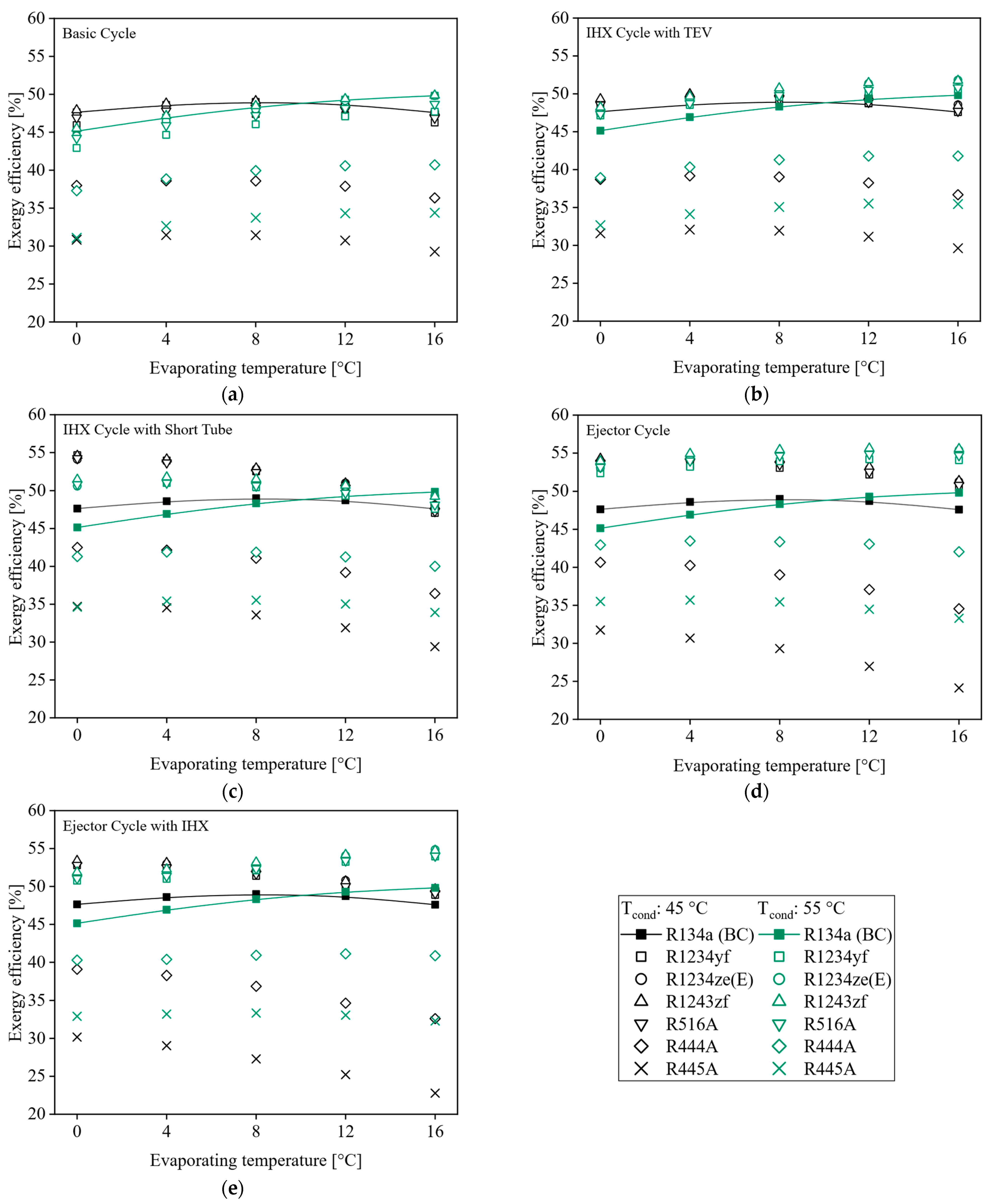
Figure 10a presents the behavior of alternative refrigerants with respect to exergy efficiency in the basic cycle configuration. There, it is observed that refrigerant R1243zf has similar exergy efficiency compared to R134a, for both condensing conditions. This is related to the total exergy destruction for this refrigerant, where the compressor exhibits lower exergy destruction, utilizing the energy supply more efficiently. The refrigerants R1234yf, R1234ze(E), and R516A exhibit a lower exergy efficiency of up to 3% compared to R134a in the basic cycle. However, refrigerants R444A and R445A have decreased by 28.0% and 44.0%, respectively. Since these refrigerants have presented lower energy efficiency in each of the evaluated cycle configurations, the most significant increase in irreversibility occurs concerning the power supply of the compressor. Additionally, large irreversibilities are generated in the expansion valve for R444A and R445A.
Figure 10b shows the impact on exergy efficiency of adding an IHX to the basic cycle operating with an expansion valve. For the condensing temperature of 45 °C, the IHXC + TEV cycle does not represent a change in the exergy efficiency. Even at evaporating temperatures higher than 8 °C, the exergy efficiency decreases, which is a consequence of a higher ratio of the total exergy destruction to the energy consumption of the cycle, since the compressor work decreases with increasing evaporating temperature and the exergy destruction is diminished, but at a lower rate.
The IHXC + ST cycle configuration represents an increase in exergy efficiency at low evaporating temperatures, as shown in Figure 10c. When a temperature of 16 °C is reached in the evaporator, for refrigerants R1234yf, R1234ze(E), R516A, and R1243zf, exergy destruction in the IHXC + ST cycle is similar to that of R134a in the basic cycle. In this case, there is a lower use of the energy supplied for these alternative refrigerants, which reduces the exergy efficiency. Likewise, R444A in the IHXC + ST cycle shows a higher exergy efficiency for an evaporating temperature of 0 °C, where the use of an IHX reduces the exergy destruction of the short tube by decreasing the enthalpy and entropy of the refrigerant at the inlet of this component.
Furthermore, the behavior of the exergy efficiency for the cycle with ejector is illustrated in Figure 10d. For all operating conditions evaluated, refrigerants R1234yf, R1234ze(E), R516A, and R1243zf exhibit an increase in exergy efficiency, which is related to a decrease in total exergy destruction for these refrigerants. Additionally, the inclusion of the ejector reduces the work required by the compressor, resulting in lower entropy generation. In contrast, refrigerants R444A and R445A show a reduction in exergy destruction under the cycle with an ejector by increasing the evaporating temperature and decreasing the exergy efficiency, because there is a high exergy destruction in the evaporator and condenser, as mentioned, and the temperature glide during the phase change involves an increase in irreversibility.
Figure 10e shows the exergy efficiency obtained for the EC + IHX configuration. The additional exergy destruction represented by the inclusion of the IHX in this cycle decreases exergy efficiency. Additionally, the negative impact of the EC + IHX cycle is greater for refrigerants R444A and R445A, as their energy transfer processes are less efficient in the heat exchange equipment, such as the evaporator, condenser, and IHX.

3.3. Exergoeconomic Analysis

3.3.1. Exergy Destruction Cost

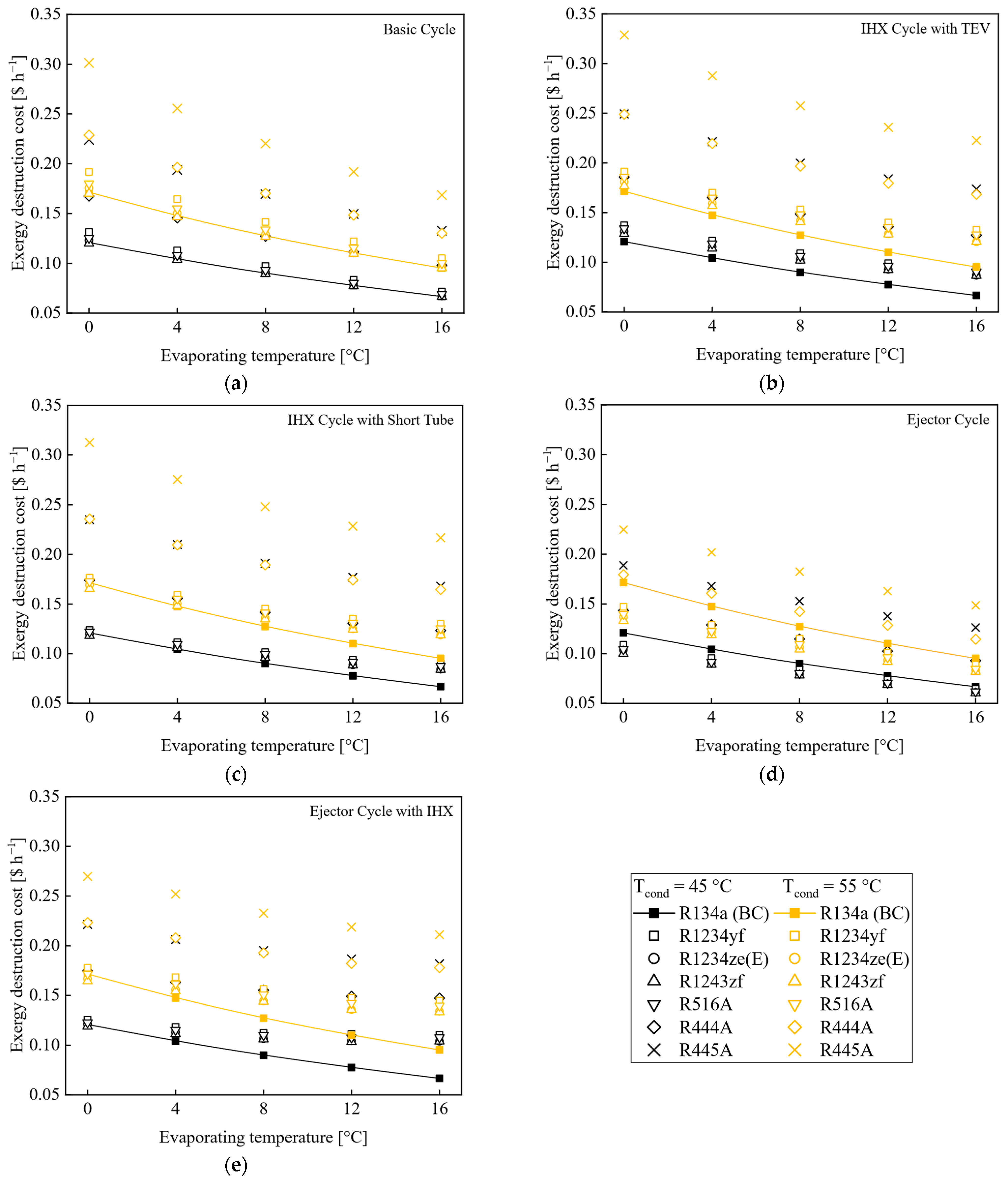
This section evaluates the costs associated with the destruction of exergy for each cycle configuration and the impact they have when compared to those of the basic cycle using R134a. In this sense, Figure 11a shows the comparison of all refrigerants operating in the basic configuration for MAC systems. For all refrigerants except R1234yf, the exergy destruction cost is higher compared to R134a due to an increase in the mass flow required for refrigerants such as R1234ze(E), R1234yf, R516A, and R445A. It is important to mention that by increasing the evaporating temperature, the cost of exergy destruction decreases because of a lower work requirement in the compressor, pressure ratio, and discharge temperature, which results in a reduction in the exergy destroyed in components such as the compressor, condenser, and expansion valve.
The total exergy destruction cost increases with the addition of extra components to the basic cycle. Figure 11b shows the impact of the inclusion of an IHX on increasing costs compared to R134a under the basic cycle. The IHX + TEV cycle increases the destruction of exergy at an evaporating temperature close to 0 °C, implying an increase in irreversibility in elements such as the compressor, condenser, and expansion valve. Likewise, the inclusion of an IHX improves the refrigerant effect in the evaporator; however, this parameter does not present a significant increase as the evaporating temperature grows, which requires the mass flow in the cycle with an IHX to ensure that the defined cooling capacity of 4 kW remains approximately constant from 0 °C to 16 °C.
In Figure 11c, the effect on exergy destruction costs when using the cycle configuration with an IHX and a short tube as the expansion element is observed. This configuration exhibits a slight improvement over the basic cycle at evaporating temperatures of 0 °C and 4 °C; however, for temperatures greater than or equal to 8 °C, the IHX + ST cycle incurs an increase in exergy destruction costs for all refrigerants. Compared to the basic cycle, the use of an IHX involves a higher discharge temperature and influences the increase in irreversibility in components such as the compressor, condenser, and short tube. In addition, the IHX is an extra source of exergy destruction, which represents an increase in exergy destruction costs for all refrigerants, mainly on refrigerants R444A and R445A. As mentioned above, the temperature glide of these mixtures reduces heat transfer efficiency in heat exchangers, increasing irreversibility and the cost of exergy destruction and, similarly, the investment cost of heat exchange equipment, since a larger transfer area is required.
Additionally, Figure 11d illustrates the behavior of exergy destruction costs in relation to the ejector cycle. There is a reduction in the costs of exergy destruction for all refrigerants, regardless of evaporating and condensing temperature conditions. Since the ejector cycle decreases the pressure ratio and discharge temperature, it also increases the refrigerant effect, which reduces the mass flow in the evaporator, implying a decrease in irreversibility in the compressor, condenser, and evaporator. Similarly, the ejector is a smaller source of exergy destruction compared to the short tube or the expansion valve. The ejector cycle has a more significant advantage at evaporating temperatures from 0 °C to 8 °C, conditions for which the discharge temperatures are the highest if we consider the basic cycle and IHX configurations. It is also important to note that the ejector cycle configuration reduces the cost of exergy destruction when operating at a condensing temperature of 55 °C. For this condition, the basic cycle and cycles with an IHX represent a ratio of pressure and discharge temperature that is high relative to their degree of reheating the vapor sucked into the compressor. In this sense, the ejector cycle with R444A operating at a condensing temperature of 55 °C and an evaporating temperature of 0 °C achieves an energy destruction cost similar to that of the basic cycle with R134a.
The cycle with an ejector and IHX does not represent an improvement in reducing the cost of exergy destruction compared to the basic cycle, as shown in Figure 11e. Although the objective of the IHX in the cycle with an ejector is to increase the degree of subcooling of the refrigerant flow at the condenser outlet, in this case, there is a disadvantage, since the pressure ratio and discharge temperature are augmented, which implies an increase in the irreversibility in the components of the cycle. In addition, the IHX contributes to additional exergy destruction, which influences the exergy destruction costs being higher compared to the basic cycle with R134a.

3.3.2. Exergoeconomic Factor

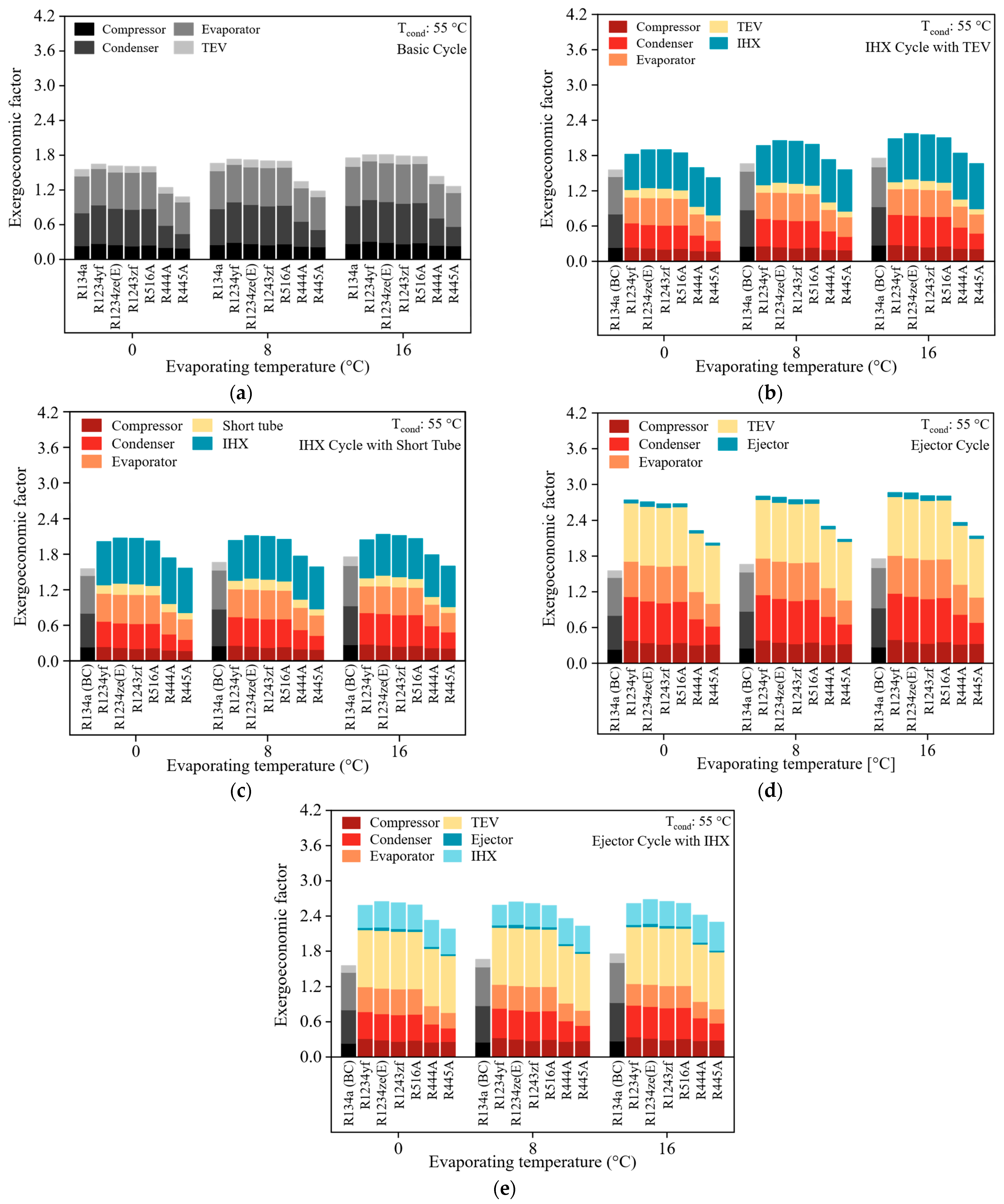
Another important parameter in cost evaluation is the exergoeconomic factor, which illustrates the relationship between the costs incurred from energy destruction and capital investment costs. Therefore, a high exergoeconomic factor reflects that the investment costs of a component are high and should be reduced. In contrast, a relatively low exergoeconomic factor indicates that equipment efficiency must be improved, thereby increasing exergy efficiency and reducing exergy destruction.
As shown in Figure 12a, refrigerants R1234yf, R1234ze(E), R1243zf, and R516A have a similar exergoeconomic factor; however, refrigerants R444A and R445A show lower exergoeconomic factor values because they have been demonstrated to be less efficient from an energy and exergy perspective. For these refrigerants, the magnitude of exergy destruction has a greater impact. Likewise, the costs of exergy destruction associated with the expansion valve in the basic cycle are high. Additionally, the exergoeconomic factor of the expansion valve is similar for all refrigerants due to the investment costs, which are a function of the pressure difference in the cycle.
When working with the IHXC + TEV cycle configuration, there is an increase in investment costs for all refrigerants compared to the basic cycle with R134a, as shown in Figure 12b. The inclusion of the IHX enhances the exergy performance of the expansion valve; however, the associated costs of the IHX contribute to a 29.3% increase in the initial investment for refrigerants R1234yf, R1234ze(E), R1243zf, and R516A. On the other hand, refrigerants R444A and R445A show a greater influence of exergy destruction costs, resulting in a lower exergoeconomic factor.
Figure 12c indicates the exergoeconomic factor for the IHXC + ST configuration. This configuration implies a higher cost of exergy destruction compared to R134a under the basic cycle, thus decreasing the exergoeconomic factor. As shown in Figure 12c, the blue bar represents the exergoeconomic factor of the IHX, which is higher compared to the other components; therefore, the significant disadvantage of the IHX in this cycle is its investment cost.
The exergoeconomic factor for the cycle with the ejector is shown in Figure 12d. For this configuration, the investment costs of the ejector are low. Although the ejector mainly influences the exergy destruction of this component, it is lower than that represented by expansion devices such as the TEV and the short tube. Additionally, the ejector promotes higher exergy efficiency and contributes to reducing exergy destruction in the other components. For the cycle with the ejector, both COP and exergy efficiency exhibit higher growth rates at high evaporating temperatures, leading to a further reduction in exergy destruction and an increase in the exergoeconomic factor. Additionally, for refrigerants R444A and R445A, the exergoeconomic factor is higher than that of the basic cycle with R134a, which is attributed to a reduction in exergy destruction costs with these refrigerants, as they exhibit lower energy and exergy efficiencies compared to R134a.
On the other hand, the EC + IHX configuration exhibits higher values for the exergoeconomic factor compared to those of R134 in the basic cycle, as shown in Figure 12e. In this case, the most significant influence on this performance parameter is provided by the expansion valve and the IHX, which results in high investment costs.

3.4. Multivariable Comparative

This section presents a graphical comparison combining energy, exergy, and economic performance parameters. In the following graphs, the improvement achieved by a particular configuration and refrigerant is contrasted when two performance parameters are analyzed simultaneously, with the basic cycle of the MAC systems using R134a as a reference. In this case, an evaporating temperature of 8 °C and a condensing temperature of 55 °C were considered.
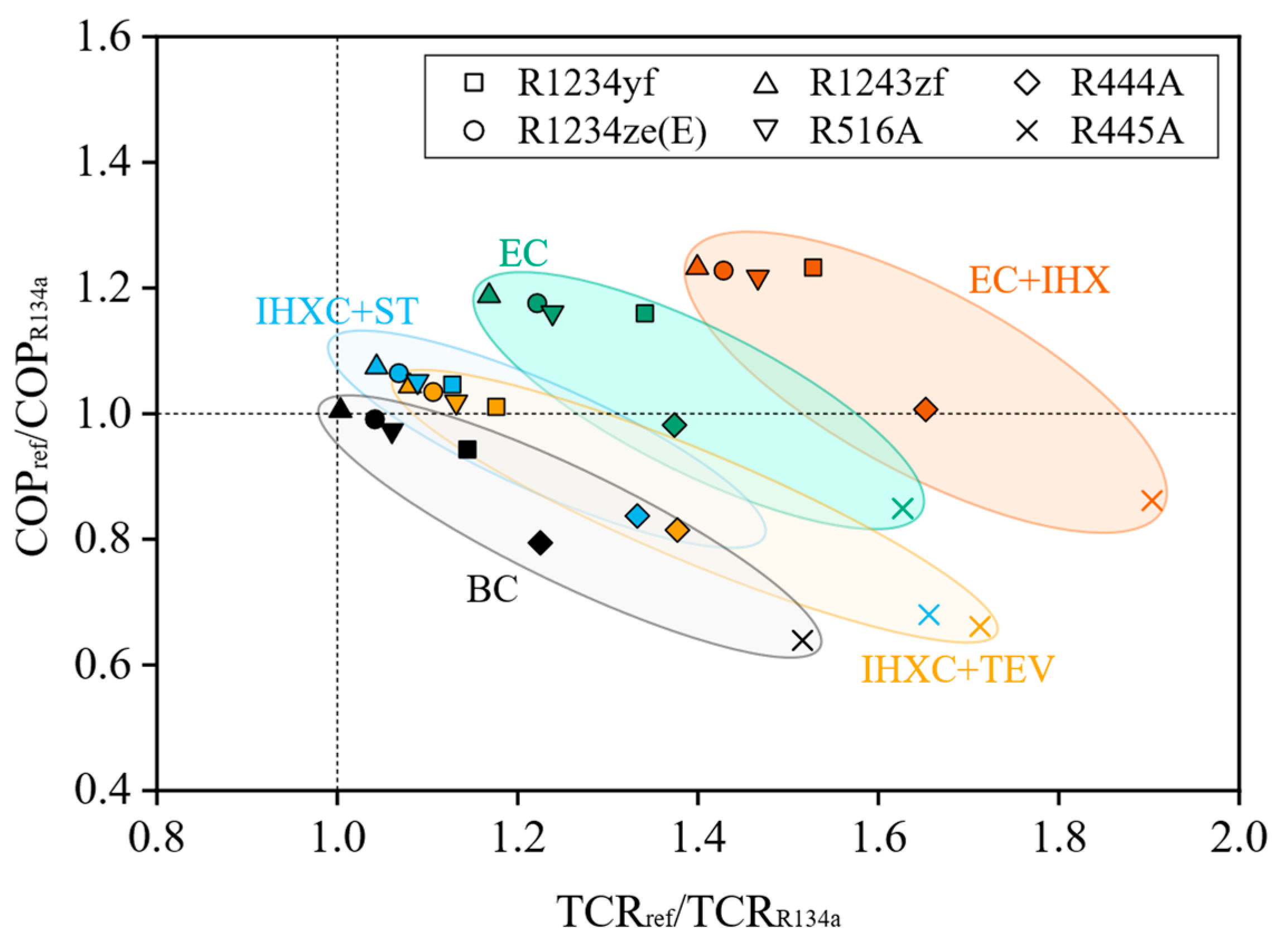
Initially, the coefficient of performance (COP) and the total cost ratio (TCR) are analyzed, for which Equations (24) and (25) are used, where the coefficient of performance of a configuration and alternative refrigerant is divided between the coefficient of performance of the basic cycle with R134a;. Therefore, the “DIFF” is the ratio that exists between the analyzed cycle configurations and “ref” is the refrigerant under evaluation, either R1234yf, R1234ze(E), R1243zf, R516A, R444A, or R445A. This procedure is similar to the total cost ratio.
C O P D I F F = C O P r e f C O P R 134 a
T C R D I F F = T C R r e f T C R R 134 a
Figure 13 shows the behavior of the COP and the total cost ratio of each cycle configuration and alternative refrigerant compared to the basic cycle with R134a. It can be seen under which configuration it is possible to improve the performance of the refrigerant to the point where it surpasses that of R134a. In this sense, the improvement in the COP implies an increase in the total cost ratio, as shown for the cycle configurations with an ejector, where performance increased; however, the costs associated with the initial investment must be considered, specifically for the cycle configurations with an ejector and an IHX.
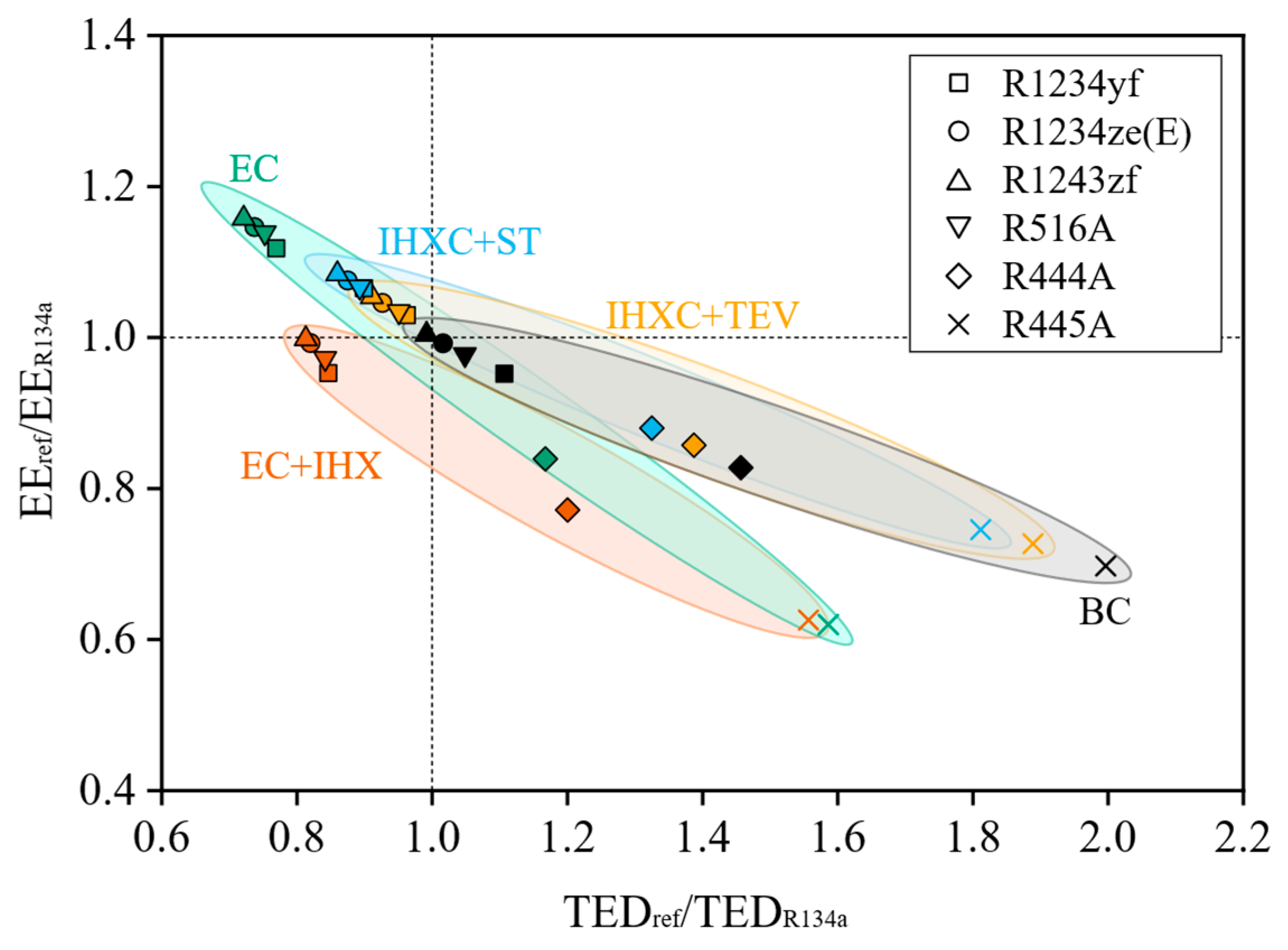
Similarly, the effect of the exergy destruction of a given cycle configuration on the exergy efficiency is compared; therefore, the total exergy destruction and exergy efficiency for all refrigerants and the five cycle configurations are analyzed using Equations (26) and (27).
E E D I F F = E E r e f E E R 134 a
T E D D I F F = T E D r e f T E D R 134 a
Figure 14 illustrates the distribution of results for each refrigerant and cycle configuration compared to the basic cycle with R134a. In this case, the cycle configurations IHXC + TEV, IHXC + ST, and EC exhibit a reduction in exergy destruction, which contributes to an increase in exergy efficiency for refrigerants R1234yf, R1234ze(E), R1243zf, and R516A. Likewise, refrigerants R444A and R445A show the lowest performance from an exergy perspective, resulting in lower effective energy consumption.
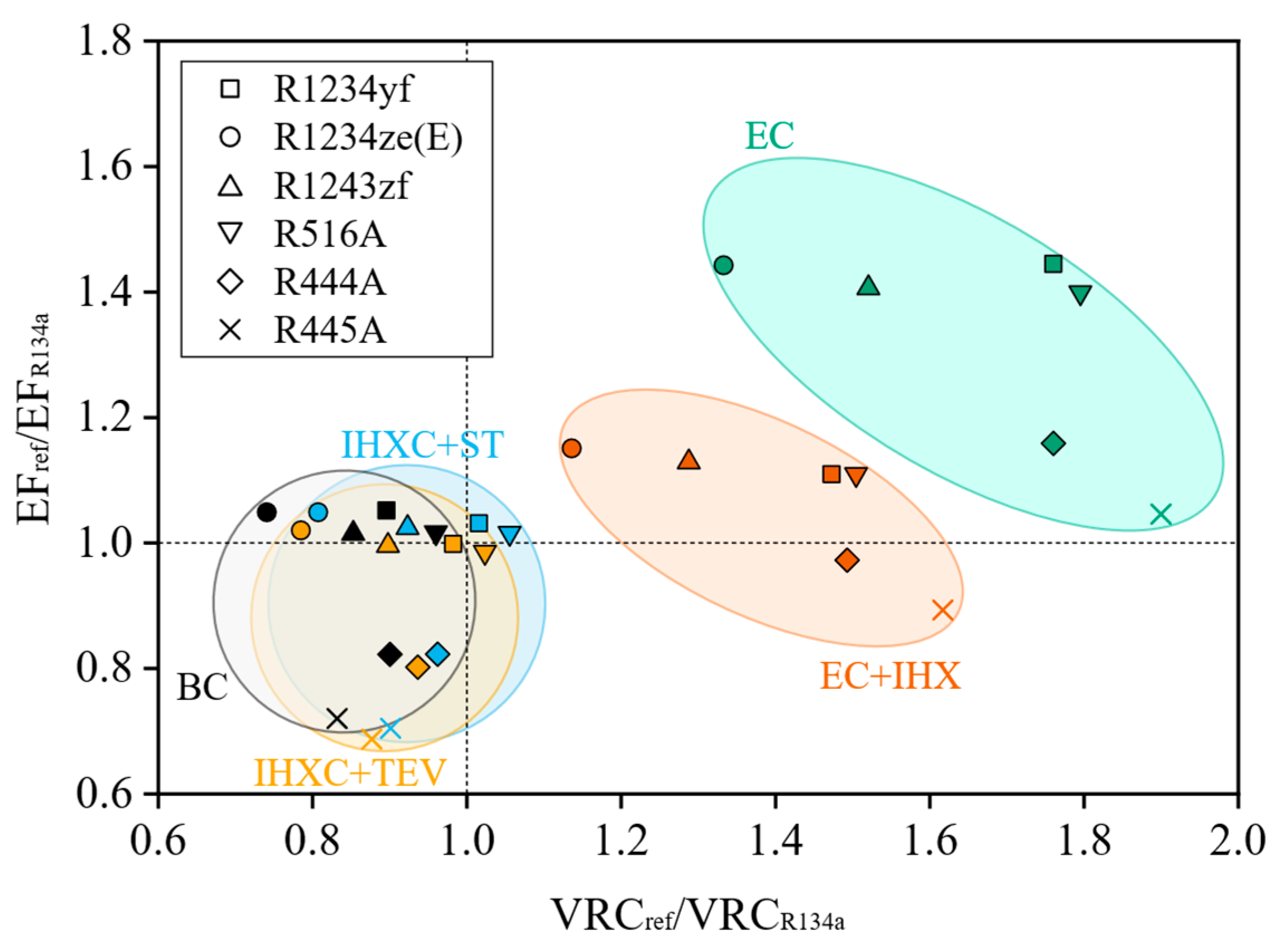
On the other hand, it is important to highlight two parameters that relate to the level of investment cost when considering an alternative cycle configuration to the basic cycle of MAC systems. In this sense, the effects of volumetric cooling capacity and the total exergoeconomic factor are compared. Since a lower volumetric cooling capacity implies a requirement for a compressor with a higher volumetric displacement capacity, the exergoeconomic factor indicates that the predominant factor is either exergy destruction costs or investment costs when using a cycle configuration and an alternative refrigerant. Therefore, using Equations (28) and (29), the volumetric refrigeration capacity and exergoeconomic factor are calculated to determine how far each refrigerant and cycle configuration deviates from the basic cycle with R134a.
E F D I F F = E F r e f E F R 134 a
V R C D I F F = V C R r e f V C R R 134 a
Figure 15 illustrates how the cycle configurations with an ejector and the one that combines the ejector with an IHX significantly enhance the volumetric refrigeration capacity. Likewise, the high exergoeconomic factor represents a high investment cost for these configurations; nevertheless, the improvement in the VRC contributes to minimizing compressor costs, as these cycle configurations can operate with a compressor of lower volumetric capacity.

3.5. Environmental Analysis

In refrigeration systems, it is essential to assess the environmental impact of their use. The TEWI index is the most widely used metric to calculate the environmental impact of a refrigeration system, from use to disposal [78]. The TEWI refers to the total amount of CO2 emissions into the environment, considering both direct emissions for refrigerant leakage and indirect emissions resulting from electricity consumption.
TEWI is commonly expressed in kilograms of CO2-eq and is calculated using Equation (30). This calculation involves evaluating direct emissions ( D E ) using Equation (31) and calculating indirect emissions ( I E ) using Equation (32).
T E W I = D E + I E
D E = G W P × M × L × A L R + ( 1 α ) × G W P × M
I E = L × A E C × β
Regarding direct emissions, these depend on the refrigerant charge ( M ), the useful life in years of refrigeration equipment ( L ), the percentage of annual refrigerant leakage ( A L R ), a recovery factor that varies from 0 to 1 and represents the percentage of refrigerant recovered at the end of the useful life of the system (α), and finally, the global warming potential ( G W P ) of the refrigerant used. In the case of indirect emissions, two additional parameters are included: A E C represents the annual energy consumption (kWh year−1), and β corresponds to the indirect emission factor (kg CO2-eq kWh−1) resulting from electricity production in the country of analysis. Table 10 shows the values established for the TEWI analysis.
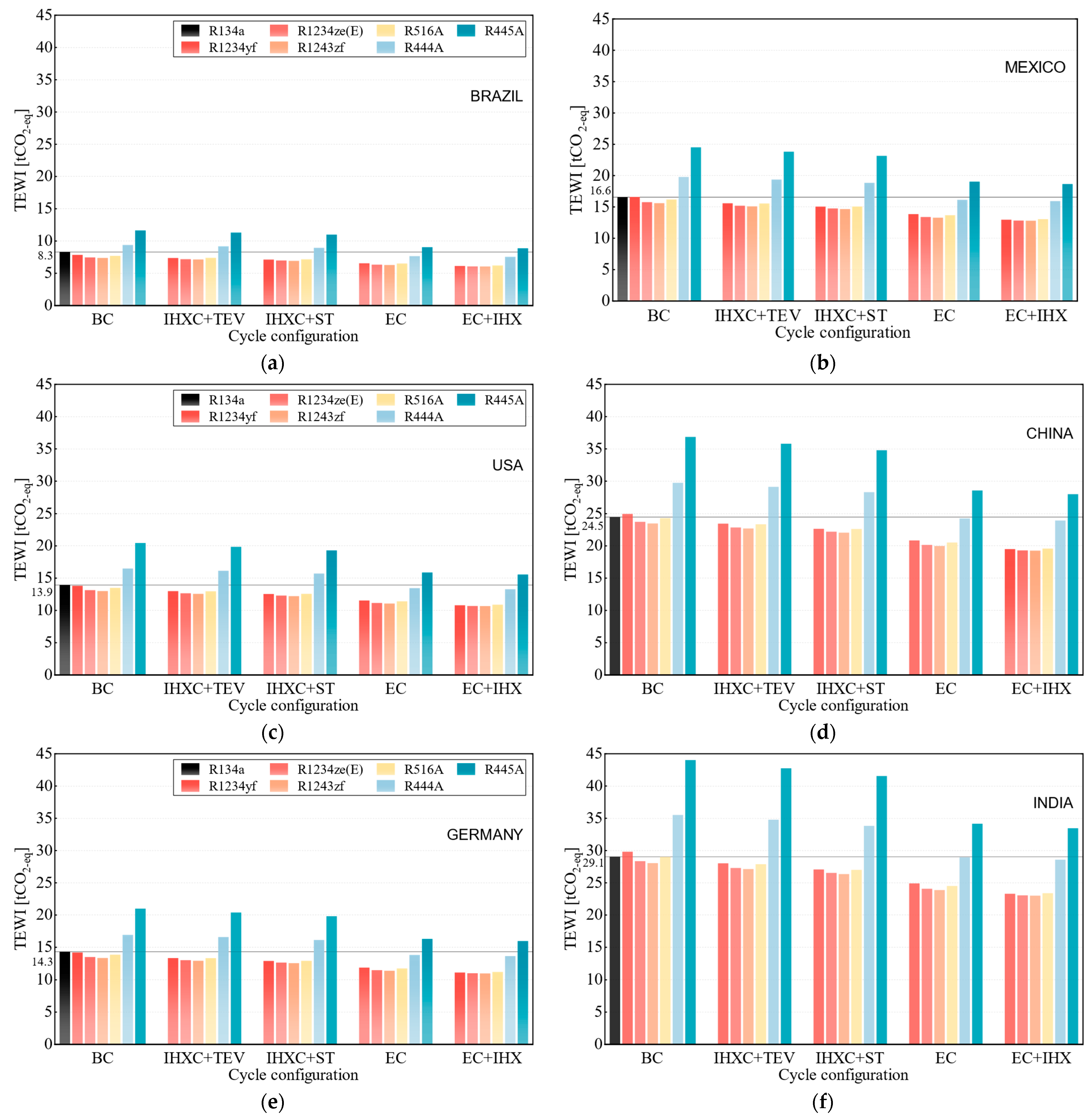
Consequently, the results are presented in Figure 16. The TEWI of the alternative refrigerants evaluated in the basic cycle shows reduced CO2 emissions to the environment, mainly due to a lower direct impact for GWP < 150. Additionally, with the adoption of configurations to the basic cycle, a greater decrease occurs with the ejector cycle configurations. Thus, the cycle with an ejector reduces emissions by up to 20% for refrigerants R1234ze(E) and R1243zf. Likewise, the cycle with an ejector and an IHX results in approximately 25% lower TEWI for refrigerants R1234yf, R1234ze(E), R1243zf, and R516A. These two cycle configurations with ejectors achieve the above results by requiring lower mass flow than other cycle configurations, resulting in lower energy consumption and, consequently, a lower indirect impact on environmental emissions.
Similarly, across the different application scenarios for the cycle configurations and refrigerants analyzed, Figure 16 shows that in the Brazil scenario, all cycle configurations using R1234yf, R1234ze(E), R1243zf, and R516A achieve a reduction in CO2 emissions. In the case of R444A and R445A, there is a decrease in TEWI when operating with the ejector cycle and the ejector cycle with an IHX. These zeotropic blends, such as R444A and R445A, show high emissions in countries where the emissions factor per kWh is too high. This is the case in countries such as China and India, where this factor can be three times higher than the emissions factor in Brazil, for example. In addition, cycle configurations with ejectors using refrigerants R1234yf, R1234ze(E), R1243zf, and R516A for the India scenario can minimize CO2 emissions by 5 to 6 tons per year. In Mexico, the USA, and Germany, substituting R1234yf, R1234ze(E), R1243zf, and R516A for R134a in the basic cycle does not result in a significant reduction in TEWI. However, with IHX cycle configurations, CO2 emissions can be reduced by 7–13%, and with ejector cycle configurations, by 18–25%.
Table 11 summarizes the numerical results of the performance of each refrigerant and cycle configuration based on the main performance parameters evaluated in this study. This summary of results was obtained at an evaporating temperature of 8 °C and a condensing temperature of 55 °C.

4. Conclusions

The use of refrigerants with GWP < 150 is a priority in mobile air conditioning systems. This study focuses on six alternative refrigerants analyzed as direct replacements for R134a in the basic cycle of MAC systems. Additionally, four cycle configurations are proposed to improve the performance of environmentally friendly refrigerants. Through the developed model and considering an analysis from an energy, exergy, exergoeconomic, and environmental perspective, the following are the main conclusions:
  • The refrigerant R1243zf exhibits the best performance as a direct replacement for R134a in the basic cycle. The COP and exergy efficiency are similar to those presented by R134a. Based on the total cost ratio, R1243zf does not represent a higher cost concerning R134a, and the reduction in volumetric cooling capacity is approximately 17%.
  • The cycle configurations with an IHX and short tube or expansion valve help to improve the COP of all refrigerants; however, for R1234yf, R1234ze(E), R1243zf, and R516A, the IHX promotes an improvement that helps to overcome the COP of R134a in the basic cycle, likewise increasing the exergy efficiency and decreases the total exergy destruction, with its impact being most significant when used at a condensing temperature of 45 °C, since at higher temperatures, the IHX increases the discharge temperature in the compressor. Hence, it decreases its benefit for alternative refrigerants.
  • The use of an IHX with R444A and R445A does not represent an increase in the performance of these refrigerants compared to R134a. In addition, the IHX promotes an increase in exergy destruction and decreases the exergy efficiency; likewise, the total cost ratio of the cycle configuration with an IHX for R444A and R445A reflects a rise of 35% and 70%, respectively.
  • The cycle with ejector and IHX shows the highest COP increase for the alternative refrigerants. Even with this configuration, R444A achieves similar performance to R134a in the basic cycle. For refrigerants R1234yf, R1234ze(E), R1243zf, and R516A, the COP increases above 20%.
  • From an exergy and exergoeconomic perspective, the ejector cycle offers a significant advantage over the basic cycle with R134a. For refrigerants R1234yf, R1234ze(E), R1243zf, and R516A, the exergy efficiency increases by over 15%, and the total exergy destruction is reduced by up to 20%. In addition, the volumetric cooling capacity increases by up to 80% when using R1234yf, R516A, and R444A refrigerants. However, the total cost ratio of refrigerants R1234yf and R444A increases by up to 40%. In this case, R1234yf in the cycle with an ejector shows an increase in exergy performance, but with a 20% increase in the total cost ratio compared to the basic cycle with R134a.
  • Through the TEWI analysis, a reduction in emissions was observed when using the alternative cycle configurations. In this sense, the cycle with an ejector and the cycle with an ejector and IHX showed the most significant reduction in terms of TEWI. The refrigerants that reduce emissions by up to 25% are R1234yf, R1234ze(E), R1243zf, and R516A.

Author Contributions

Conceptualization, methodology, and writing—original draft preparation, D.M.-M. and V.P.-G.; software, D.M.-M. and J.F.I.-Y.; investigation, visualization, and data curation, D.M.-M.; resources, D.M.-M. and J.J.R.-M.; writing—review and editing, V.P.-G., J.F.I.-Y., J.J.R.-M. and J.M.B.-F.; supervision, V.P.-G., J.F.I.-Y. and J.J.R.-M.; project administration, V.P.-G. and J.M.B.-F. All authors have read and agreed to the published version of the manuscript.

Funding

This research received no external funding.

Institutional Review Board Statement

Not applicable.

Informed Consent Statement

Not applicable.

Data Availability Statement

The original contributions presented in this study are included in the article. Further inquiries can be directed to the corresponding author.

Acknowledgments

D.M.-M. acknowledges the financial support received from CONAHCYT by means of the doctoral scholarship.

Conflicts of Interest

The authors declare no conflicts of interest.

Nomenclature

Aarea, m2
cunit exergy cost, $ kJ−1
C ˙ exergy cost rate, $ h−1
Cthermal capacitance, kW K−1
Cpspecific heat, kJ kg−1 K−1
Ddiameter, m
D L characteristic diameter, m
E ˙ exergy rate, kW
f exergoeconomic factor
Gmass velocity, kg m−2 s−1
ggravitational constant, m s−2
htransfer coefficient, W m−2 K−1
i r interest rate, %
jColburn factor
kthermal conductivity, W m−2 K−1
m ˙ mass flow rate, kg s−1
Nlifetime, year
Ppressure, kPa
PrPrandtl number
Q ˙ heat transfer rate, kW
ReReynolds number
t o p annual operating time, h
P pressure drop, kPa
Ttemperature, °C
Uglobal heat transfer coefficient, W m−2 K−1
μ e j e ejector entrainment ratio
Vvelocity, m s−1
W ˙ power consumption, kW
xQuality
Zcost, $
Z ˙ levelized investment cost rate, $ h−1
Greek Symbols
effectiveness
η efficiency
difference
ρ density, kg m−3
φ operation and maintenance cost factor
σ surface tension, N m−1
μ viscosity, Pa s−1
Subscripts
aair
CCcold current
CIcapital investment
compcompressor
condcondenser
Ddestruction
disdischarge
ejeejector
evapevaporator
ffuel
fnfin
HChot current
ininlet
iseisentropic
kk th component
lliquid
mixmixture
motmotive
oambient (dead state)
OMoperating and maintenance
optoptimal
outoutlet
pproduct
refrefrigerant
refereference
STshort tube
sucsuction
SUPsuperheating
TOTtotal
vvapor
Abbreviations
BCbasic cycle
COPcoefficient of performance
CRFcapital recovery factor
ECejector cycle
EC + IHXejector cycle + internal heat exchanger
GWPglobal warming potential
HFChydrochlorofluorocarbon
HFOhydrofluoroolefine
IHXC + TEVcycle with internal heat exchanger + thermostatic expansion valve
IHXC + STcycle with internal heat exchanger + short tube
MACmobile air conditioning
NTUnumber of transfer units
TEVthermostatic expansion valve

Appendix A. Heat Exchanger Model

The ε-NTU methodology is used to analyze heat transfer in the evaporator, condenser, and internal heat exchanger. According to Kays and London [88] the effectiveness of heat exchangers is determined by the ratio of thermal capacities to the number of transfer units ( N T U ). In single-phase fluid zones, the thermal capacity ratio is nonzero; when there is a phase change in the fluid, it is zero. This is reflected in the Equation (A2); for each condition, the corresponding equation is used.
ε = Q Q m a x = Q ( m ˙ C p ) m i n ( T m a x )
ε = { 1 e x p { ( 1 C r ) N T U 0.22 [ exp ( C r N T U 0.78 ) 1 ] } ,     C r 0 1 exp ( N T U ) ,     C r = 0
C r = C m i n C m a x
C m i n = { ( m ˙ C p ) r e f ,     ( m ˙ C p ) a > ( m ˙ C p ) r e f ( m ˙ C p ) a       ,     ( m ˙ C p ) a < ( m ˙ C p ) r e f
Equations (A5) and (A6) are used to calculate the convective coefficient during evaporation and condensation.
h e v a p = 0.087 R e 0.6 P r l ( ρ l ρ v ) ( k l k v ) ( k l D L )
h c o n d = h l ( x o u t x i n ) [ ( 1 x ) 0.8 1.8 + 3.8 P r 0.38 ( x 1.76 1.76 0.04 x 2.76 2.76 ) ] x i n x o u t
To determine the heat transfer coefficient of the refrigerant in single-phase flow, the Dittus and Boelter correlation is used [89], Equation (A7).
h r e f = 0.023 ( k D ) R e 0.8 P r 0.3
Were,
R e = ρ l V m D L μ l
V m = ( G ρ l ) [ 1 x ( ρ l ρ v 1 ) ]
D L = [ σ r e f g ( ρ l ρ v ) ] 0.5
To determine the heat transfer area associated with the evaporator, condenser, and IHX, the Equation (A11) is used.
N T U = U A C m i n
1 U A = 1 η a h a A a + 1 h r e f A r e f
1 U A I H X = 1 h r e f , H A r e f , H + 1 h r e f , C A r e f , C
The equations that complete the heat transfer analysis are shown below [90].
h a = j C p a G m a x P r 2 / 3
η a = 1 N f n A f n A T O T ( 1 η f n )

References

  1. Molinaroli, L.; Lucchini, A.; Colombo, L.P.M. Drop-in Analysis of R450A and R513A as Low-GWP Alternatives to R134a in a Water-to-Water Heat Pump. Int. J. Refrig. 2022, 135, 139–147. [Google Scholar] [CrossRef]
  2. Velders, G.J.M.; Andersen, S.O.; Daniel, J.S.; Fahey, D.W.; McFarland, M. The Importance of the Montreal Protocol in Protecting Climate. Proc. Natl. Acad. Sci. USA 2007, 104, 4814–4819. [Google Scholar] [CrossRef]
  3. Craig, T. Secondary loop mobile air conditioners (SL-MAC) demonstration project briefing. In Proceedings of the MAC Workshop at the California Air Resources Board, Sacramento, CA, USA, 15 June 2018; Available online: https://www.ccacoalition.org (accessed on 17 September 2025).
  4. Flerlage, H.; Velders, G.J.M.; De Boer, J. A Review of Bottom-up and Top-down Emission Estimates of Hydrofluorocarbons (HFCs) in Different Parts of the World. Chemosphere 2021, 283, 131208. [Google Scholar] [CrossRef]
  5. The European Parliament; The Council of the European Union. Directive 2006/40/EC of The European Parliament and of the Council of 17 May 2006 relating to emissions from air-conditioning systems in motor vehicles & amending council directive 70/156/EC. Off. J. Eur. Union Legis. 2006, 161, 12–18. [Google Scholar]
  6. Mendoza-Miranda, J.M.; Mota-Babiloni, A.; Navarro-Esbrí, J. Evaluation of R448A and R450A as Low-GWP Alternatives for R404A and R134a Using a Micro-Fin Tube Evaporator Model. Appl. Therm. Eng. 2016, 98, 330–339. [Google Scholar] [CrossRef]
  7. Environmental Protection Agency (EPA). Protection of Stratospheric Ozone: Change of Listing Status for Certain Sustitutes Under the Significant New Alternatives Policy Program, Rules and Regulations; Environmental Protection Agency (EPA): Washington, DC, USA, 2015; p. 80.
  8. Birmpili, T. Montreal Protocol at 30: The Governance Structure, the Evolution, and the Kigali Amendment. Comptes Rendus. Geosci. 2018, 350, 425–431. [Google Scholar] [CrossRef]
  9. United Nations. Hottest July ever Signals ‘Era of Global Boiling has Arrived’ Says UN Chief. UN News, Global Perpesctive Human Stories. 2023. Available online: https://news.un.org/en/story/2023/07/1139162 (accessed on 30 September 2025).
  10. Chakravarty, P. Climate Communication Channels, AI, and Indigenous Wisdom: A Triad Approach for Adaptation in the Era of Global Boiling. Glob. Clim. Assoc. 2023. Available online: https://www.researchgate.net/profile/Poulomi-Chakravarty-3/publication/373895266_Climate_Communication_Channels_AI_and_Indigenous_Wisdom_A_Triad_Approach_for_Adaptation_in_the_Era_of_Global_Boiling/links/6501db29a2e39316ce083d5d/Climate-Communication-Channels-AI-and-Indigenous-Wisdom-A-Triad-Approach-for-Adaptation-in-the-Era-of-Global-Boiling.pdf (accessed on 10 October 2025).
  11. Mota-Babiloni, A.; Makhnatch, P. Predictions of European Refrigerants Place on the Market Following F-Gas Regulation Restrictions. Int. J. Refrig. 2021, 127, 101–110. [Google Scholar] [CrossRef]
  12. Mohanraj, M.; Abraham, J.D.A.P. Environment Friendly Refrigerant Options for Automobile Air Conditioners: A Review. J. Therm. Anal. Calorim. 2022, 147, 47–72. [Google Scholar] [CrossRef]
  13. Prabakaran, R.; Mohan Lal, D. A Novel Exergy Based Charge Optimisation for a Mobile Air Conditioning System: An Experimental Study. J. Therm. Anal. Calorim. 2018, 132, 1241–1252. [Google Scholar] [CrossRef]
  14. Rajendran, P.; Sidney, S.; Ramakrishnan, I.; Dhasan, M.L. Experimental Studies on the Performance of Mobile Air Conditioning System Using Environmental Friendly HFO-1234yf as a Refrigerant. Proc. Inst. Mech. Eng. Part E J. Process Mech. Eng. 2021, 235, 731–742. [Google Scholar] [CrossRef]
  15. Prabakaran, R.; Lal, D.M.; Devotta, S. Effect of Thermostatic Expansion Valve Tuning on the Performance Enhancement and Environmental Impact of a Mobile Air Conditioning System. J. Therm. Anal. Calorim. 2021, 143, 335–350. [Google Scholar] [CrossRef]
  16. Prabakaran, R.; Sidney, S.; Lal, D.M.; Harish, S.; Kim, S.C. Experimental Performance of a Mobile Air Conditioning Unit with Small Thermal Energy Storage for Idle Stop/Start Vehicles. J. Therm. Anal. Calorim. 2022, 147, 5117–5132. [Google Scholar] [CrossRef]
  17. Ortega Sotomayor, P.; Parise, J.A.R. Characterization and Simulation of an Open Piston Compressor for Application on Automotive Air-Conditioning Systems Operating with R134a, R1234yf and R290. Int. J. Refrig. 2016, 61, 100–116. [Google Scholar] [CrossRef]
  18. Sánchez, D.; Cabello, R.; Llopis, R.; Arauzo, I.; Catalán-Gil, J.; Torrella, E. Energy Performance Evaluation of R1234yf, R1234ze(E), R600a, R290 and R152a as Low-GWP R134a Alternatives. Int. J. Refrig. 2017, 74, 269–282. [Google Scholar] [CrossRef]
  19. Mota-Babiloni, A.; Navarro-Esbrí, J.; Barragán-Cervera, Á.; Molés, F.; Peris, B. Drop-in Analysis of an Internal Heat Exchanger in a Vapour Compression System Using R1234ze(E) and R450A as Alternatives for R134a. Energy 2015, 90, 1636–1644. [Google Scholar] [CrossRef]
  20. Mota-Babiloni, A.; Navarro-Esbrí, J.; Mendoza-Miranda, J.M.; Peris, B. Experimental Evaluation of System Modifications to Increase R1234ze(E) Cooling Capacity. Appl. Therm. Eng. 2017, 111, 786–792. [Google Scholar] [CrossRef]
  21. Devecioğlu, A.G.; Oruç, V. An Analysis on the Comparison of Low-GWP Refrigerants to Alternatively Use in Mobile Air-Conditioning Systems. Therm. Sci. Eng. Prog. 2017, 1, 1–5. [Google Scholar] [CrossRef]
  22. Haro-Ortuño, J.; Mota-Babiloni, A.; Navarro-Esbrí, J.; Barragán-Cervera, A. Comparación teórica entre los refrigerantes R404A y R445A en sistemas de refrigeración. Rev. Iberoam. Ing. Mecánica 2019, 23, 39–47. [Google Scholar]
  23. Poongavanam, G.; Sivalingam, V.; Prabakaran, R.; Salman, M.; Kim, S.C. Selection of the Best Refrigerant for Replacing R134a in Automobile Air Conditioning System Using Different MCDM Methods: A Comparative Study. Case Stud. Therm. Eng. 2021, 27, 101344. [Google Scholar] [CrossRef]
  24. Prabakaran, R.; Lal, D.M.; Prabhakaran, A.; Kumar, J.K. Experimental Investigations on the Performance Enhancement Using Minichannel Evaporator with Integrated Receiver-Dryer Condenser in an Automotive Air Conditioning System. Heat Transf. Eng. 2019, 40, 667–678. [Google Scholar] [CrossRef]
  25. Lambert, M.A.; Jones, B.J. Automotive Adsorption Air Conditioner Powered by Exhaust Heat. Part 1: Conceptual and Embodiment Design. Proc. Inst. Mech. Eng. Part D J. Automob. Eng. 2006, 220, 959–972. [Google Scholar] [CrossRef]
  26. International Energy Agency. Net Zero by 2050: A Roadmap for the Global Energy Sector; OECD Publishing: Paris, France, 2021. [Google Scholar]
  27. Zhang, Q.; Tu, R.; Yang, X. Performance Analyses of a Novel Free-Cooling Assisted Air Conditioning System Applied to Electrical Vehicles. Appl. Therm. Eng. 2024, 238, 122003. [Google Scholar] [CrossRef]
  28. Cho, H.; Lee, H.; Park, C. Performance Characteristics of an Automobile Air Conditioning System with Internal Heat Exchanger Using Refrigerant R1234yf. Appl. Therm. Eng. 2013, 61, 563–569. [Google Scholar] [CrossRef]
  29. Direk, M.; Soylu, E. The Effect of Internal Heat Exchanger Using R1234ze(E) as an Alternative Refrigerant in a Mobile Air Conditioning System. Stroj. Vestn.-J. Mech. Eng. 2018, 64, 114–120. [Google Scholar] [CrossRef]
  30. Fang, J.; Yin, X.; Wang, A.; Sun, X.; Liu, Y.; Cao, F. Cooling Performance Enhancement for the Automobile Transcritical CO2 Air Conditioning System with Various Internal Heat Exchanger Effectiveness. Appl. Therm. Eng. 2021, 196, 117274. [Google Scholar] [CrossRef]
  31. Pérez-García, V.; Belman-Flores, J.; Rodríguez-Muñoz, J.; Rangel-Hernández, V.; Gallegos-Muñoz, A. Second Law Analysis of a Mobile Air Conditioning System with Internal Heat Exchanger Using Low GWP Refrigerants. Entropy 2017, 19, 175. [Google Scholar] [CrossRef]
  32. Wang, D.; Zhang, Z.; Yu, B.; Wang, X.; Shi, J.; Chen, J. Experimental Research on Charge Determination and Accumulator Behavior in Trans-Critical CO2 Mobile Air-Conditioning System. Energy 2019, 183, 106–115. [Google Scholar] [CrossRef]
  33. Kawamoto, Y.; Ogata, G.; Shan, Z. Ejector Energy-Saving Technology for Mobile Air Conditioning Systems. SAE Int. J. Passeng. Cars—Mech. Syst. 2017, 10, 102–110. [Google Scholar] [CrossRef]
  34. Lawrence, N.; Elbel, S. Experimental and analytical investigation of automotive ejector air-conditioning cycles using low-pressure refrigerants. In Proceedings of the International Refrigeration and Air Conditioning Conference, West Lafayette, IN, USA, 16 July 2012. [Google Scholar]
  35. Méndez Méndez, D.; Pérez García, V.; Solorio Alvarado, A.I.; Belman Flores, J.M.; Ramírez Minguela, J.D.J. Energy and Consumption Fuel Study for a Mobile Air Conditioning System Using Ejector and R445A As a Replacement Alternative for R134a. In Proceedings of the Fluids Engineering; Heat Transfer and Thermal Engineering, Columbus, OH, USA, 30 October 2022; American Society of Mechanical Engineers: New York, NY, USA, 2023; Volume 8, p. V008T11A039. [Google Scholar] [CrossRef]
  36. Li, H.; Zhang, Z.; Song, X.; Chen, J. Experimental study of a transcritical CO2 mobile air conditioning system with an ejector. J. Shanghai Jiaotong Univ. 2021, 55, 179. [Google Scholar]
  37. Brodie, B.R.; Takano, Y.; Gocho, M. Evaporator with Integrated Ejector for Automotive Cabin Cooling. In Proceedings of the SAE 2012 World Congress & Exhibition, Detroit, MI, USA, 16 April 2012. [Google Scholar]
  38. Al-Chlaihawi, K.K.I.; Kadhim, H.T.; Yousif, A.H. A Comparative Performance Study of an Ejector-Expansion Refrigeration Cycle Using R134a and Its Alternatives: Application of Automobile Air Conditioning. Int. J. Air-Cond. Ref. 2021, 29, 2150035. [Google Scholar] [CrossRef]
  39. Haider, M.; Elbel, S. Development of a New Ejector Performance Map for Design of an Automotive Air Conditioning System. In Proceedings of the SAE 2005 World Congress & Exhibition, Detroit, MI, USA, 14 April 2020. [Google Scholar]
  40. Li, H.; Cao, F.; Bu, X.; Wang, L.; Wang, X. Performance Characteristics of R1234yf Ejector-Expansion Refrigeration Cycle. Appl. Energy 2014, 121, 96–103. [Google Scholar] [CrossRef]
  41. Chen, Q.; Yan, G.; Yu, J. Performance Analysis of an Ejector Enhanced Refrigeration Cycle with R290/R600a for Application in Domestic Refrigerator/Freezers. Appl. Therm. Eng. 2017, 120, 581–592. [Google Scholar] [CrossRef]
  42. Chen, Q.; Hwang, Y.; Yan, G.; Yu, J. Theoretical Investigation on the Performance of an Ejector Enhanced Refrigeration Cycle Using Hydrocarbon Mixture R290/R600a. Appl. Therm. Eng. 2020, 164, 114456. [Google Scholar] [CrossRef]
  43. Sanaye, S.; Refahi, A. A Novel Configuration of Ejector Refrigeration Cycle Coupled with Organic Rankine Cycle for Transformer and Space Cooling Applications. Int. J. Refrig. 2020, 115, 191–208. [Google Scholar] [CrossRef]
  44. Sarkar, J. Ejector Enhanced Vapor Compression Refrigeration and Heat Pump Systems—A Review. Renew. Sustain. Energy Rev. 2012, 16, 6647–6659. [Google Scholar] [CrossRef]
  45. Steven Brown, J.; Yana-Motta, S.F.; Domanski, P.A. Comparitive Analysis of an Automotive Air Conditioning Systems Operating with CO2 and R134a. Int. J. Refrig. 2002, 25, 19–32. [Google Scholar] [CrossRef]
  46. Cho, H.; Park, C. Experimental Investigation of Performance and Exergy Analysis of Automotive Air Conditioning Systems Using Refrigerant R1234yf at Various Compressor Speeds. Appl. Therm. Eng. 2016, 101, 30–37. [Google Scholar] [CrossRef]
  47. Khatoon, S.; Karimi, M.N. Thermodynamic Analysis of Two Evaporator Vapor Compression Refrigeration System with Low GWP Refrigerants in Automobiles. Int. J. Air-Cond. Ref. 2023, 31, 2. [Google Scholar] [CrossRef]
  48. Meng, Z.; Zhang, H.; Lei, M.; Qin, Y.; Qiu, J. Performance of Low GWP R1234yf/R134a Mixture as a Replacement for R134a in Automotive Air Conditioning Systems. Int. J. Heat Mass Transf. 2018, 116, 362–370. [Google Scholar] [CrossRef]
  49. Qi, Z. Performance Improvement Potentials of R1234yf Mobile Air Conditioning System. Int. J. Refrig. 2015, 58, 35–40. [Google Scholar] [CrossRef]
  50. Subiantoro, A.; Ooi, K.T.; Stimming, U. Energy saving measures for automotive air conditioning (AC) system in the tropics. In Proceedings of the International Refrigeration and Air Conditioning Conference, West Lafayette, IN, USA, 14–17 July 2014; no. Paper 1361. [Google Scholar]
  51. Vaghela, J.K. Comparative Evaluation of an Automobile Air—Conditioning System Using R134a and Its Alternative Refrigerants. Energy Procedia 2017, 109, 153–160. [Google Scholar] [CrossRef]
  52. Zhao, Y.; Qi, Z.; Chen, J.; Xu, B.; He, B. Experimental Analysis of the Low-GWP Refrigerant R1234yf as a Drop-in Replacement for R134a in a Typical Mobile Air Conditioning System. Proc. Inst. Mech. Eng. Part C J. Mech. Eng. Sci. 2012, 226, 2713–2725. [Google Scholar] [CrossRef]
  53. Meng, Z.; Cui, X.; Liu, Y.; Wang, S.; Du, C.; Hu, R. Performance of R1234yf and R513A as Alternatives to R134A in Automotive Air Conditioning Systems in Winter. Therm. Sci. 2023, 27, 1937–1946. [Google Scholar] [CrossRef]
  54. Zhang, W.; Li, W.; Cernicin, V.; Hrnjak, P. Theoretical and Experimental Investigation on the Effects of Internal Heat Exchangers on a Reversible Automobile R744 Air-Conditioning System under Various Operating Conditions. Appl. Therm. Eng. 2024, 236, 121569. [Google Scholar] [CrossRef]
  55. Gao, Y.; He, G.; Cai, D.; Fan, M. Performance Evaluation of a Modified R290 Dual-Evaporator Refrigeration Cycle Using Two-Phase Ejector as Expansion Device. Energy 2020, 212, 118614. [Google Scholar] [CrossRef]
  56. Metsue, A.; Nesreddine, H.; Bartosiewicz, Y.; Poncet, S. Theoretical Analysis of the Optimal Ejector Operation and Design within an Ejector-Based Refrigeration System. Int. J. Refrig. 2024, 168, 334–344. [Google Scholar] [CrossRef]
  57. Liu, J.; Lin, Z. A Novel Dual-Temperature Ejector-Compression Heat Pump Cycle—Exergetic and Economic Analyses. Int. J. Refrig. 2021, 126, 155–167. [Google Scholar] [CrossRef]
  58. Wang, M.; Cheng, Y.; Yu, J. Analysis of a Dual-Temperature Air Source Heat Pump Cycle with an Ejector. Appl. Therm. Eng. 2021, 193, 116994. [Google Scholar] [CrossRef]
  59. Di Cairano, L.; Bou Nader, W.; Nemer, M. A Simulation and Experimental Study of an Innovative MAC/ORC/ERC System: ReverCycle with an Ejector for Series Hybrid Vehicles. Energy 2021, 230, 120830. [Google Scholar] [CrossRef]
  60. Rodríguez-Muñoz, J.L.; Pérez-García, V.; Belman-Flores, J.M.; Ituna-Yudonago, J.F.; Gallegos-Muñoz, A. Energy and Exergy Performance of the IHX Position in Ejector Expansion Refrigeration Systems. Int. J. Refrig. 2018, 93, 122–131. [Google Scholar] [CrossRef]
  61. Lemmon, E.W.; Bell, I.H.; Huber, M.L.; McLinden, M.O. NIST Standard Reference Database 23: Reference Fluid Thermodynamic and Transport Properties-REFPROP, version 10.0; National Institute of Standards and Technology: Gaithersburg, MA, USA, 2018.
  62. Gonzalves, V.A.; Parise, J.A. A Study on the Reduction of Throttling Losses in Automotive Air Conditioning Systems Through Expansion Work Recovery. In Proceedings of the International Refrigeration and Air Conditioning Conference, West Lafayette, IN, USA, 14–17 July 2008. no. Paper 882. [Google Scholar]
  63. Belman-Flores, J.M.; Barroso-Maldonado, J.M.; Mendoza-Miranda, J.M.; Gallegos-Muñoz, A.; Riesco-Ávila, J.M.; Rubio-Maya, C. Simulación energética de un aire acondicionado automotriz trabajando con refrigerantes R-1234yf y R-134a. In Proceedings of the Memorias del XIX Congreso Internacional Anual de la SOMIM, Pachuca, México, 25–27 September 2013. [Google Scholar]
  64. Hussain, Z.; You, N.; Cho, H. Performance and Energy Evaluation of R450A, R1234yf, R513A, R516A, R152A, and R1234ze(E) as Alternatives to R134A in an Air Conditioner. Appl. Therm. Eng. 2025, 271, 126319. [Google Scholar] [CrossRef]
  65. Ashour, A.M.; Ali, H.M.; Kadhim, S.A.; Hammoodi, K.A.; Rashid, F.L.; Sathyamurthy, R.; Bouabidi, A. Energy, Exergy, and Environmental Analysis of Five Low-GWP Refrigerants Considered as Alternatives to R410A for Air Conditioning Systems. Int. J. Air-Cond. Refrig. 2025, 33, 18. [Google Scholar] [CrossRef]
  66. Seybold, L.; Hill, W.; Lazaridis, I. Internal Heat Exchanger Integration for a Dual Evaporator MAC System. SAE Int. J. Mater. Manuf. 2013, 6, 549–566. [Google Scholar] [CrossRef]
  67. Gohel, J. Thermodynamic Cycle Analysis of Mobile Air Conditioning System Using Hydrofluoroolefin (R1234yf and R1234ze) as an Alternative Refrigerants to R134a. Int. J. Veh. Perform. 2017, 3, 259. [Google Scholar] [CrossRef]
  68. Elattar, H.; Fouda, A.; Al-Zahrani, A.; Alshareef, R.; Almohammadi, B. Improving Automotive Air Conditioning Systems’ (AACs) Thermodynamic Performance with Eco-Friendly Azeotropic Refrigerant Blends. Therm. Sci. 2026, 30, 575–589. [Google Scholar] [CrossRef]
  69. Alkan, A. Theoretical Comparison Analysis of R134a, R1234yf, R452A and R454C Refrigerants Used in Automobile, Trailer and Commercial and Industrial Cooling Systems. Eur. Mech. Sci. 2024, 8, 47–53. [Google Scholar] [CrossRef]
  70. Bejan, A.; Tsatsaronis, G.; Moran, M.J. Thermal Design and Optimization; Wiley: New York, NY, USA, 1996. [Google Scholar]
  71. Baakeem, S.S.; Orfi, J.; Alabdulkarem, A. Optimization of a Multistage Vapor-Compression Refrigeration System for Various Refrigerants. Appl. Therm. Eng. 2018, 136, 84–96. [Google Scholar] [CrossRef]
  72. Khosravi, A.; Koury, R.N.N.; Machado, L. Thermo-Economic Analysis and Sizing of the Components of an Ejector Expansion Refrigeration System. Int. J. Refrig. 2018, 86, 463–479. [Google Scholar] [CrossRef]
  73. Deniz, E.; Yılmaz, C.; Karagöz, M.; Sarıdemir, S.; Işıktaş, A. 4E Analysis and Operational Vibration in Domestic Refrigeration Systems: Effects of Refrigerant Charge and Thermal Load. Int. Commun. Heat Mass Transf. 2025, 169, 109571. [Google Scholar] [CrossRef]
  74. Mortazavi, H.; Beni, H.M.; Nadooshan, A.A.; Islam, M.S.; Ghalambaz, M. 4E Analysis and Triple Objective NSGA-II Optimization of a Novel Solar-Driven Combined Ejector-Enhanced Power and Two-Stage Cooling (EORC-TCRC) System. Energy 2024, 294, 130803. [Google Scholar] [CrossRef]
  75. Wang, Y.; Ye, Z.; Yin, X.; Song, Y.; Cao, F. Energy, Exergy and Exergoeconomic Evaluation of the Air Source Transcritical CO2 Heat Pump with Internal Heat Exchanger for Space Heating. Int. J. Refrig. 2021, 130, 14–26. [Google Scholar] [CrossRef]
  76. Tontu, M.; Sahin, B.; Bilgili, M. Exergoeconomic Analysis of Steam Turbine Driving Vapor Compression Refrigeration System in an Existing Coal-Fired Power Plant. Arab. J. Sci. Eng. 2019, 44, 7553–7566. [Google Scholar] [CrossRef]
  77. Economic Indicators. Marshall and Swift equipment cost index. Chem. Eng. 2011, 72. Available online: https://www.scribd.com/document/210910055/Marshall-Index-2011 (accessed on 15 March 2026).
  78. United Nations Industrial Development Organization (UNIDO). Preparing for HCFC Phase-Out: Fundamentals of Uses, Alternatives, Implications and Funding for Article 5 Countries; UNIDO: Vienna, Austria, 2009. [Google Scholar]
  79. Li, K.; Yu, J.; Liu, M.; Xu, D.; Su, L.; Fang, Y. A Study of Optimal Refrigerant Charge Amount Determination for Air-Conditioning Heat Pump System in Electric Vehicles. Energies 2020, 13, 657. [Google Scholar] [CrossRef]
  80. Su, S.; Fang, X.; Li, L.; Wu, J.; Zhang, J.; Xu, W.; Hu, J. HFC-134a Emissions from Mobile Air Conditioning in China from 1995 to 2030. Atmos. Environ. 2015, 102, 122–129. [Google Scholar] [CrossRef]
  81. Yuan, Z.; Ou, X.; Peng, T.; Yan, X. Development and Application of a Life Cycle Greenhouse Gas Emission Analysis Model for Mobile Air Conditioning Systems. Appl. Energy 2018, 221, 161–179. [Google Scholar] [CrossRef]
  82. Mateu-Royo, C.; Mota-Babiloni, A.; Navarro-Esbrí, J.; Barragán-Cervera, Á. Comparative Analysis of HFO-1234ze(E) and R-515B as Low GWP Alternatives to HFC-134a in Moderately High Temperature Heat Pumps. Int. J. Refrig. 2021, 124, 197–206. [Google Scholar] [CrossRef]
  83. Méndez-Méndez, D.; Pérez-García, V.; Belman-Flores, J.M.; Riesco-Ávila, J.M.; Barroso-Maldonado, J.M. Internal Heat Exchanger Influence in Operational Cost and Environmental Impact of an Experimental Installation Using Low GWP Refrigerant for HVAC Conditions. Sustainability 2022, 14, 6008. [Google Scholar] [CrossRef]
  84. IIR (International Institute of Refrigeration). 35th Informatory Note on Refrigeration Technologies/The Impact of the Refrigeration Sector on Climate Change; IIR: Paris, France, 2017. [Google Scholar]
  85. AIRAH. Methods of Calculating Total Equivalent Warming Impact (TEWI); Australian Institute of Refrigeration, Air Conditioning and Heating: Melbourne, Australia, 2012. [Google Scholar]
  86. Comisión Nacional para el Uso Eficiente de la Energía (CONUEE). Transición Energética: Generación de Energía Fotovoltaica. 2024. Available online: https://www.gob.mx/cms/uploads/attachment/file/1046949/Generaci_n_de_energ_a_fotovoltaica.pdf (accessed on 20 December 2025).
  87. Zeppelin. Conversion Factors CO2 Emissions. 2024. Available online: https://sustainabilityreport.zeppelin.com/2024/appendix/conversion-factors-CO2-emissions/ (accessed on 22 December 2025).
  88. Kays, W.M.; London, A.L. Compact Heat Exchangers, 3rd ed.; McGraw-Hill: New York, NY, USA, 1984. [Google Scholar]
  89. Dittus, F.W.; Boelter, L.M.K. Heat Transfer in Automobile Radiators of the Tubular Type. Int. Commun. Heat Mass Transf. 1985, 12, 3–22. [Google Scholar] [CrossRef]
  90. McQuiston, F.C.; Parker, J.D.; Spitler, J.D. Heating, Ventilating, and Air Conditioning Analysis and Design; John Wiley and Sons: Hoboken, NJ, USA, 1994. [Google Scholar]
Figure 1. Number of publications on the refrigerants under study in MAC systems from 2011 to date.
Applsci 16 03071 g001
Figure 2. Scheme and P-h diagram for (a) basic cycle, (b) cycle with IHX and thermostatic expansion valve, and (c) cycle with IHX and short tube.
Applsci 16 03071 g002
Figure 3. Scheme and diagram P-h of cycle configurations with an ejector: (a) ejector cycle (EC); (b) ejector cycle with IHX (EC + IHX).
Applsci 16 03071 g003
Figure 4. Comparison of the present cycle model with ejector with two references: (a) [40]; (b) [55].
Applsci 16 03071 g004
Figure 5. Sensitivity analysis of COP in response to variations in the efficiency of the ejector sections for the configurations (a) EC and (b) EC + IHX.
Applsci 16 03071 g005
Figure 6. Comparison of the incidence of isentropic efficiency with different references based on performance parameters (a) pressure ratio [66,67,68] and (b) COP [21,49,69].
Applsci 16 03071 g006
Figure 7. Behavior of volumetric refrigeration capacity vs. evaporating temperature for (a) BC, (b) IHX + TEV, (c) IHX + ST, (d) EC, and (e) EC + IHX.
Applsci 16 03071 g007
Figure 8. COP evolution with varying evaporating temperature depending on the cycle configuration: (a) BC; (b) IHXC + TEV; (c) IHXC + ST; (d) EC; (e) EC + IHX.
Applsci 16 03071 g008
Figure 9. Exergy destruction for different evaporating temperatures under the following cycle configurations: (a) BC; (b) IHXC + TEV; (c) IHXC + ST; (d) EC; (e) EC + IHX.
Applsci 16 03071 g009
Figure 10. Exergy efficiency vs. evaporating temperature using different cycle configurations: (a) BC; (b) IHXC + TEV; (c) IHXC + ST; (d) EC; (e) EC + IHX.
Applsci 16 03071 g010
Figure 11. Exergy destruction cost ratio of varying evaporating temperature by cycle configuration: (a) BC; (b) IHXC + TEV; (c) IHXC + ST; (d) EC; (e) EC + IHX.
Applsci 16 03071 g011
Figure 12. Exergoeconomic factor for cycle configurations at different evaporating temperatures: (a) BC; (b) IHXC + TEV; (c) IHXC + ST; (d) EC; (e) EC + IHX.
Applsci 16 03071 g012
Figure 13. Comparison of COP and total cost ratio for alternative cycle configurations.
Applsci 16 03071 g013
Figure 14. Comparison of exergy efficiency and total exergy destruction for alternative cycle configurations.
Applsci 16 03071 g014
Figure 15. Comparison of exergoeconomic factor and volumetric refrigeration capacity for alternative cycle configurations.
Applsci 16 03071 g015
Figure 16. TEWI for different cycle configurations for MAC system in different scenarios: (a) Brazil; (b) Mexico; (c) USA; (d) China; (e) Germany; (f) India.
Applsci 16 03071 g016
Table 1. Installed base and projection of new systems with alternative refrigerants in MAC systems [11].
MAC ApplicationInstalled Base, 2010New Systems, 2021New Systems, 2030
cars, trucks, taxis100% R134a100% HFO5% Naturals
95% HFO
Buses, trains80% R134a50% R134a20% Naturals
20% R410A20% R410A55% HFO
10% HFO25% R32
20% R513A
Table 2. Governing equations for the analysis of the ejector in the following configurations: EC and EC + IHX.
Section of EjectorGoverning Equation
Motive nozzle P 4 d ; 5 e = P 9 d ; 10 e P
h 4 d ; 5 e = h 3 d ; 4 e η m o t ( h 3 d ; 4 e h 4 d ; 5 e , s )
V 4 d ; 5 e = 2 ( h 3 d ; 4 e h 4 d ; 5 e )
A 4 d ; 5 e = 1 ( 1 + μ e j e ) ρ 4 d ; 5 e V 4 d ; 5 e
Suction nozzle P 10 d ; 11 e = P 9 d ; 10 e P
h 10 d ; 11 e = h 9 d ; 10 e η s u c ( h 9 d ; 10 e h 10 d ; 11 e , s )
V 10 d ; 11 e = 2 ( h 9 d ; 10 e h 10 d ; 11 e )
A 10 d ; 11 e = 1 ( 1 + μ e j e ) ρ 10 d ; 11 e V 10 d ; 11 e
Mixing section P 5 d ; 6 e = P 4 d ; 5 e = P 10 d ; 11 e
V 5 d ; 6 e = η m i x ( 1 1 + μ e j e V 4 d ; 5 e + μ e j e 1 + μ e j e V 10 d ; 11 e )
h 5 d ; 6 e = 1 1 + μ e j e ( h 4 d ; 5 e + V 4 d ; 5 e 2 2 ) + μ e j e 1 + μ e j e ( h 10 d ; 11 e + V 10 d ; 11 e 2 2 ) V 5 d ; 6 e 2 2
Diffuser section h 6 d ; 7 e = h 5 d ; 6 e + V 5 d ; 6 e 2 2
h 6 d ; 7 e , s = h 5 d ; 6 e + η d i f ( h 6 d ; 7 e h 5 d ; 6 e )
P 6 d ; 7 e = P ( h 6 d ; 7 e , s , s 5 d ; 6 e )
Balance equation x 6 d ; 7 e = 1 1 + μ e j e
Liquid-Vapor
separator
h 1 d ; 12 e = h ( P 6 d ; 7 e , x = 1 )
h 7 d ; 8 e = h ( P 6 d ; 7 e , x = 0 )
Table 3. Input parameters for simulation of cycle configurations.
ParameterValueReferences
Evaporating temperature, T e v a p 0 °C to 16 °C[28,30,45,48,52]
Condensing temperature, T c o n d 45 °C and 55 °C[49,50]
Superheating TEV for BC and IHXC, S u p 5 °C[48,53]
Effectiveness IHX, ϵ 0.7[30,31,54]
Isentropic efficiency motive nozzle, η m o t 0.85[55,56,57,58,59,60]
Isentropic efficiency suction nozzle, η s u c 0.85[55,56,57,58,59,60]
Isentropic efficiency mixing section, η m i x 0.9[55,56,57,58,59,60]
Isentropic efficiency diffuser, η d i f 0.85[55,56,57,58,59,60]
Reference state temperature, T o 25 °C-
Reference state pressure, P o 101.3 kPa-
Cooling capacity, Q ˙ e v a p 4.0 kW[51]
Table 4. Environmental characteristics and thermophysical properties of the refrigerants under study.
PropertyR134aR1234yfR1234ze(E)R1243zfR516AR444AR445A
CompositionPurePurePurePure77.5%-R1234yf
14%-R152a
8.5%-R134a
83%-R1234ze(E)
12%-R32
5%-R152a
85%-R1234ze(E)
9%-R134a
6%-R744
GWP143011114292130
ASHRAE Safety classA1A2LA2LA2LA2LA2LA2L
Temperature glide, °C000004.094.14
Critical pressure, kPa4059.33382.23634.93517.93654.44472.84461.2
Critical temperature, °C101.194.7109.4103.897.2106.3104.9
Boiling point at 1 atm, °C−26.1−29.5−19−25.4−29.4−51.7−21.5
Molecular weight, kg kmol−110211411496.1102.696.7103.1
Saturation pressure, kPa292.8315.8216.5269.5318.7390.9551.4
Liquid density, kg m−31294.81176.31240.11047.01147.91199.81232.3
Vapor density, kg m−314.417.611.712.516.012.712.7
Latent heat of vaporization, kJ kg−1198.6163.3184.2200.7183.8202.6191.4
Liquid thermal conductivity, mW m−1 K−192.071.583.178.878.892.988.2
Vapor thermal conductivity, mW m−1 K−111.511.611.612.212.011.912.1
Liquid viscosity, µPa.s266.5204.7262.6209.2207.8227.7242.3
Vapor viscosity, µPa.s10.710.710.210.410.311.011.1
All properties were considered at 0 °C as reference temperature using NIST REFPROP 10.0 software.
Table 5. Operating conditions of different references for comparing isentropic efficiency.
Operating Conditions[66][67][68][21][49][69]
Evaporating temperature, °C307.5550
Condensing temperature, °C455535606560
Table 6. Parameters used for the exergoeconomic analysis [71].
ItemDescriptionValue
i r Interest rate, %10
N Lifetime, year15
t o p e Annual operating time, h4000
φ Operation and maintenance cost factor, %1
Table 7. Equations for evaluating the investment costs of the components of cycle configurations.
EquipmentCost Function EquationReferences
Compressor Z c o m p = ( 573 m ˙ r e f 0.8996 η i s e ) ( P c o n d P e v a p ) ln ( P c o n d P e v a p ) [72]
Condenser Z c o n d = 516.621 × A c o n d + 268.45 [73,74]
Evaporator Z e v a = 309.143 × A e v a p + 231.915 [73,74]
IHX Z I H X = 1874.4 × ( A I H X ) 0.9835 [75]
Ejector Z e j e = 750 m ˙ m o t × ( T m o t P m o t ) 0.05 ( P d i f ) 0.75 [72]
TEV Z T E V = 37 × ( P c o n d P e v a p ) 0.68 [76]
Table 8. Equations for exergy and cost analysis of cycle components.
ComponentExergy EquationsCost Equations
Compressor E ˙ D ,   c o m p = W ˙ c o m p ( E ˙ o u t E ˙ i n ) C ˙ o u t = C ˙ i n + C ˙ w , c o m p + Z ˙ c o m p
Condenser E ˙ D ,   c o n d = ( E ˙ i n E ˙ o u t ) ( 1 T o T c o n d ) Q ˙ c o n d C ˙ o u t = C ˙ i n + C ˙ q , c o n d + Z ˙ c o n d
Evaporator E ˙ D ,   e v a p = ( E ˙ i n E ˙ o u t ) + ( 1 T o T e v a p ) Q ˙ e v a p C ˙ o u t = C ˙ i n + C ˙ q , e v a p + Z ˙ e v a p
Thermostatic expansion valve E ˙ D ,   T E V = E ˙ i n E ˙ o u t C ˙ o u t = C ˙ i n + Z ˙ T E V
Short tube E ˙ D ,   S T = E ˙ i n E ˙ o u t C ˙ o u t = C ˙ i n + Z ˙ S T
IHX E ˙ D ,   I H X = ( E ˙ i n ,   H E ˙ o u t , H ) ( E ˙ o u t ,   C E ˙ i n , C ) C ˙ o u t , H + C ˙ o u t , C = C ˙ i n , H + C ˙ i n , C + Z ˙ I H X
Ejector E ˙ D ,   e j e = ( E ˙ m o t + E ˙ s u c ) E ˙ d i f C ˙ d i f = C ˙ m o t + C ˙ s u c + Z ˙ e j e
Table 9. Percentage of exergy destruction for each cycle configuration.
Applsci 16 03071 i001
BCExergy Destruction Percentage [%]
ComponentR134aR1234yfR1234ze(E)R1243zfR516AR444AR445A
Compressor40.2737.4741.4839.338.2438.9140.58
Condenser14.2811.4912.6313.1812.6418.6922.47
Evaporator11.9810.7511.8112.0411.3811.398.3
TEV33.4740.2834.0835.4937.7531.0128.66
IHXC + TEVExergy Destruction Percentage [%]
ComponentR134aR1234yfR1234ze(E)R1243zfR516AR444AR445A
Compressor38.2337.0640.0737.9737.1436.7538.31
Condenser26.6423.3624.0325.0624.9329.2931.82
Evaporator13.8313.9614.314.4814.0114.0210.58
TEV14.1116.5113.7914.5315.5915.0115.48
IHX7.199.117.827.968.334.943.81
IHXC + STExergy Destruction Percentage [%]
ComponentR134aR1234yfR1234ze(E)R1243zfR516AR444AR445A
Compressor38.9737.8640.8338.737.9237.2638.74
Condenser26.2622.9523.624.6524.5328.9431.52
Evaporator13.3113.2313.713.8813.3613.9410.53
ST12.9515.1212.5513.2914.314.0314.7
IHX8.5210.859.319.489.95.844.51
ECExergy Destruction Percentage [%]
ComponentR134aR1234yfR1234ze(E)R1243zfR516AR444AR445A
Compressor42.7239.6643.7241.8240.6536.6735.25
Condenser16.7414.915.6216.0915.6520.9225.54
Evaporator16.615.4616.3716.6816.0419.3918.18
Ejector23.4829.2323.8424.927.0222.5920.61
TEV0.470.750.450.520.640.430.41
EC + IHXExergy Destruction Percentage [%]
ComponentR134aR1234yfR1234ze(E)R1243zfR516AR444AR445A
Compressor37.5936.1139.1537.2936.3633.0832.53
Condenser27.7424.5825.0726.1526.0829.4632.34
Evaporator15.915.9116.3416.4716.0118.9218.18
Ejector8.9210.988.99.3310.1912.1712.1
TEV0.410.660.390.450.560.410.44
IHX9.4411.7610.1410.3110.85.964.41
Table 10. Parameters used for TEWI analysis.
ParameterUnitsValueReferences
Refrigerant charge, M kg0.6[13,79,80,81]
System lifetime, L years15[82,83]
Annual leakage rate, A L R kg year−10.05[84]
Refrigerant recovery factor, α%7[85]
Indirect emission factor, β , for:kg CO2-eq kWh−1
Mexico-0.444[86]
Brazil-0.21[87]
USA-0.37[87]
China-0.668[87]
Germany 0.38[87]
India-0.798[87]
Table 11. Summary of results for the refrigerants with respect to the main performance parameters considering each configuration evaluated: (a) BC; (b) IHXC + TEV; (c) IHXC + ST; (d) EC; (e) EC + IHX.
BCVRC
[kJ m−3]
COP E ˙ D ; T O T
[kW]
η e x
[%]
C ˙ D ; T O T
[$ h−1]
C ˙ T O T
[$ h−1]
TEWIMEXICO
[tCO2-eq]
TEWICHINA
[tCO2-eq]
Refrigerant
R134a2367.613.40.60848.330.1270.19516.5624.46
R1234yf2123.023.210.67246.050.1420.22316.5924.96
R1234ze(E)1759.633.380.61548.030.1290.20415.7723.73
R1243zf2014.83.410.60448.470.1270.19615.623.48
R516A2270.823.310.63847.230.1340.20716.1824.3
R444A2132.712.70.88939.950.170.23919.7829.74
R445A1973.762.171.21633.740.220.29420.4536.86
(a)
IHXC + TEVVRC
[kJ m−3]
COP E ˙ D ; T O T
[kW]
η e x
[%]
C ˙ D ; T O T
[$ h−1]
C ˙ T O T
[$ h−1]
TEWIMEXICO
[tCO2-eq]
TEWICHINA
[tCO2-eq]
Refrigerant
R134a2433.883.450.58249.770.1440.21916.3324.11
R1234yf2308.833.420.5949.570.1530.23415.5923.46
R1234ze(E)1853.993.510.56550.470.1420.21915.1922.85
R1243zf2110.313.530.58850.750.1410.21515.0922.71
R516A2406.013.450.58349.810.1480.22515.5523.35
R444A2208.942.760.85141.30.1970.27219.3729.12
R445A2069.612.241.15735.070.2580.33823.8235.8
(b)
IHXC + STVRC
[kJ m−3]
COP E ˙ D ; T O T
[kW]
η e x
[%]
C ˙ D ; T O T
[$ h−1]
C ˙ T O T
[$ h−1]
TEWIMEXICO
[tCO2-eq]
TEWICHINA
[tCO2-eq]
Refrigerant
R134a2501.783.550.55750.530.1390.21315.923.47
R1234yf2388.423.540.5650.440.1450.22515.0622.66
R1234ze(E)1906.893.610.54151.190.1360.21314.7622.21
R1243zf2171.23.630.53451.490.1350.20814.6622.06
R516A2482.133.560.55550.630.1410.21715.0722.62
R444A2269.652.840.8241.880.1890.26518.8515.72
R445A2127.692.311.11735.540.2480.32823.1634.8
(c)
ECVRC
[kJ m−3]
COP E ˙ D ; T O T
[kW]
η e x
[%]
C ˙ D ; T O T
[$ h−1]
C ˙ T O T
[$ h−1]
TEWIMEXICO
[tCO2-eq]
TEWICHINA
[tCO2-eq]
Refrigerant
R134a4040.554.010.44755.210.1040.18214.1820.88
R1234yf4023.43.840.47953.920.1150.21813.8620.85
R1234ze(E)3060.243.980.45354.970.1060.19613.420.16
R1243zf3479.424.010.44455.440.1040.18613.2819.99
R516A4099.633.920.46254.670.1090.19613.6820.53
R444A4032.463.310.68443.360.1420.21916.1424.25
R445A4360.682.810.91935.440.1820.26819.0428.6
(d)
EC + IHXVRC
[kJ m−3]
COP E ˙ D ; T O T
[kW]
η e x
[%]
C ˙ D ; T O T
[$ h−1]
C ˙ T O T
[$ h−1]
TEWIMEXICO
[tCO2-eq]
TEWICHINA
[tCO2-eq]
Refrigerant
R134a3450.284.080.46652.420.1460.25513.9620.54
R1234yf3404.564.110.46652.120.1560.27312.9619.5
R1234ze(E)2636.884.150.45352.930.1450.25712.8319.31
R1243zf2978.184.160.4553.180.1440.25212.8119.27
R516A3476.594.110.46452.350.1510.26213.0519.59
R444A3464.733.360.70440.930.1930.30315.9323.94
R445A3750.942.870.92933.340.2330.34918.6528.02
(e)
Disclaimer/Publisher’s Note: The statements, opinions and data contained in all publications are solely those of the individual author(s) and contributor(s) and not of MDPI and/or the editor(s). MDPI and/or the editor(s) disclaim responsibility for any injury to people or property resulting from any ideas, methods, instructions or products referred to in the content.