1. Introduction
1.1. Background and Motivation
Exoskeletons, orthoses, exosuits, and similar assistive robots are specialized wearable devices designed to support the human body in targeted ways. They enhance or protect the body by applying external forces that assist movement, improve strength, or provide stability.
Exoskeletons have received considerable attention in recent years, with promising applications in rehabilitation, industrial assistance and mobility support [
1,
2,
3]. These wearable mechanical or robotic systems aim to enhance human capabilities, reduce physical strain [
4] and assist people with mobility impairments during rehabilitation [
5].
Thorough evaluation is necessary for the development of exoskeletons. Traditionally, user testing has been employed for this purpose. This type of evaluation requires a large number of test subjects and is very costly.
1.2. Simulation-Based Evaluation of Exoskeletons
Compared to traditional user tests, simulation-based approaches such as musculoskeletal simulations (MSSs) allow researchers to analyze complex interactions between the human body and assistive devices. This accelerates the design process, providing safer and more cost-effective testing while reducing the need for traditional user testing.
Simulation models provide valuable insights into exoskeletons’ mechanical performance, actuator behavior and control strategies [
6]. By simulating the complex interaction between an exoskeleton and the human body, researchers can evaluate key design parameters and assess biomechanical effects prior to physical implementation [
7,
8].
Multi-body simulations play a central role in analyzing the structural and functional aspects of exoskeletons. These simulations help to refine mechanical components, optimize actuator efficiency and improve control algorithms to ensure smooth and effective operation [
9]. In addition, musculoskeletal simulations (MSSs) based on multi-body simulations allow a detailed investigation of how an exoskeleton affects human movement and musculoskeletal load distribution [
6].
1.3. Research Gap and Methodological Contribution
One of the major challenges is accurately representing reality in the simulation. We aim to improve accuracy by using a novel approach of an empirical “exoskeleton support modeling” from Reimeir et al. [
10]. The model was created using test data for characteristic values from a test rig. This model was then implemented into an automated MSS pipeline in MATLAB R2023a using the OpenSim 4.3 application programming interface (API) [
11]. This approach enhances the efficient evaluation of biomechanical effects to support the iterative optimization of exoskeleton designs prior to physical testing.
A typical MSS in OpenSim 4.3 consists of several simulation tools that offer individual biomechanical evaluation criteria. The inverse kinematics approach allows the investigation of the occurring joint angles. The inverse dynamics analysis enables the calculation of external joint moments on the human body. Insights into the human body are gained with the static optimization approach that calculates the resulting muscle forces and activations. These muscle forces allow the calculation of the level of the shoulder muscles’ energy consumption during a movement. Finally, joint reaction analysis allows the simulation of resulting joint reaction forces, i.e., the acting of forces occurring inside the joint itself.
1.4. Biomechanical Focus: Shoulder Joint Loading During Arm Evaluation
Upper arm elevation is a major risk factor for work-related shoulder joint injuries, such as rotator cuff syndrome and subacromial impingement syndrome [
12,
13]. Parsons et al. [
14] demonstrated an increase in glenohumeral joint reaction force when the shoulder was abducted in vitro. To provide a more meaningful assessment, this study divides the joint reaction force into orthogonal and tangential components in relation to the glenohumeral joint. This type of analysis enables a more targeted examination of the subacromial space, which can get strained during overhead activities [
15].
1.5. State of the Art
The investigation of the resulting joint angles allows the analysis of changes in movement behavior due to the exoskeleton support. Yamamoto et al. [
16] used the resulting movement patterns to analyze the effect of different ankle exoskeleton stiffnesses on the gait behavior of patients in order to evaluate the ability to recreate healthier gait patterns. Zhang et al. [
17] analyzed the resulting joint angles in gait as an evaluation criterion in order to identify the required support of an ankle exoskeleton. The same approach was used by Akbas et al. [
18] to investigate the resulting gait behavior of patients due to the different supports of a knee exoskeleton.
The analysis of resulting external joint moments enables to evaluate altered loads on the human body. Thus, Yamamoto et al. [
16] also investigated the joint moments to analyze the effects of the different ankle exoskeleton stiffnesses on the humans. Afschrift et al. [
19] identified the required support of an ankle exoskeleton by the difference in occurring net joint moments in the ankle during the gait of patients.
The simulation of muscle forces and muscle activations allows the investigation of altering occurring stresses on the human body due to exoskeleton support and enables implications on alterations on the metabolic cost [
20]. Farris et al. [
21] simulated the effects on the lower leg muscles to analyze the resulting stresses due to the support of an ankle exoskeleton. Wu et al. [
22] used the resulting muscle forces and activations to identify the optimal setting of a lower limb exoskeleton and to quantify its benefit for the user. Michaud et al. [
23] investigated the expenditure in muscle energy for the support with an ankle–knee exoskeleton during crutch-assisted gait. Fritzsche et al. [
24] and van der Have et al. [
25] evaluated the efficiency of a passive shoulder exoskeleton during over-head tasks by analyzing the resulting muscle activations in the shoulder muscles. The analysis of required metabolic energy was used by Bianco et al. [
26] und Dembia et al. [
27] to identify the optimal support of an exoskeleton during the gait to the various joints (hip, knee, ankle).
Joint reaction analysis allows the investigation of loadings on the joint’s passive structures. Fritzsche et al. [
24] analyzed the glenohumeral antero-posterior force in the shoulder joint during the support of a passive shoulder exoskeleton. Thereby, the resulting amount of force was compared with and without exoskeleton. Molz et al. [
2] compared different shoulder exoskeleton support concepts, which they referred to as morphologies, by the resulting muscle activations. They also analyzed the resulting joint reactions forces in the shoulder, but could only find small deviations due to the support concepts. Chander et al. [
28] analyzed the changing knee joint reaction force with the support of a knee exoskeleton when walking on stairs. Here, mainly the resulting magnitude of force was analyzed. Christensen et al. [
29] evaluated an upper arm exoskeleton and thereby analyzed the resulting reaction force in the elbow and shoulder. However, the magnitude of force was also considered. Zhou et al. [
30] analyzed shoulder exoskeleton during a lifting task. They just analyzed the maximum occurring reaction force in comparison between with and without exoskeleton use. Tröster et al. [
31] looked at the resulting glenohumeral reaction force to analyze different configurations of the shoulder exoskeleton to support healthcare workers in the surgery waiting room, but also just the resulting magnitude was of interest.
All studies for the joint reaction force just analyze the magnitude of the resulting joint reaction force, which has a definitive impact on the human body’s joint health. However, in addition to the pure magnitude, the direction of force and the parts in the joint that are loaded are also of high interest, as strains and damages can occur.
1.6. Approach
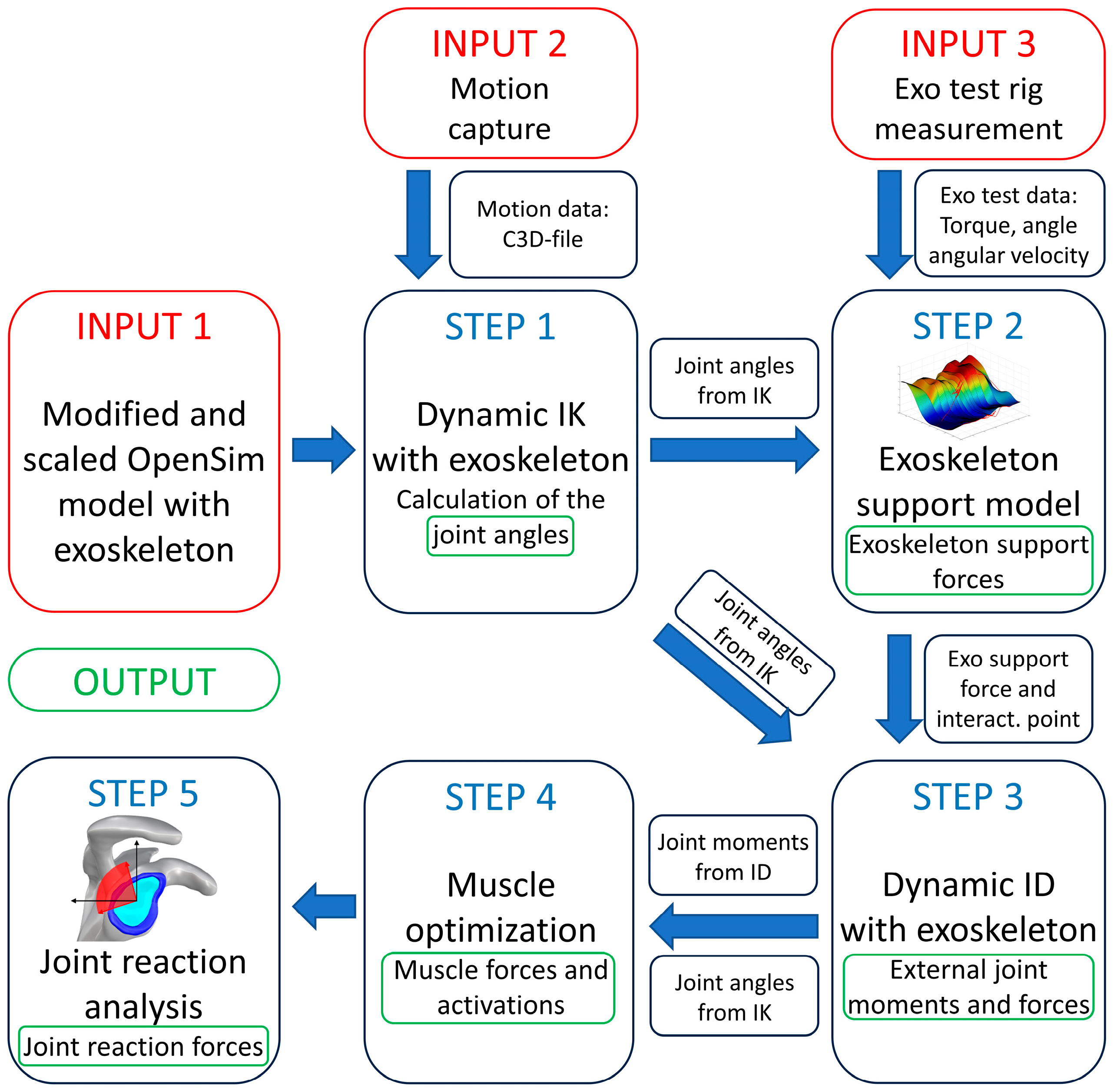
To improve usability and customizability in human shoulder–exoskeleton-interaction simulations, a MATLAB-based automation pipeline was developed using the OpenSim API. The resulting outputs of the pipeline provide insights into joint kinematics, external joint torques, muscle activations, and joint reaction forces, aiding in the assessment and development of exoskeletons. Most of the methods considered in the pipeline correspond to standard practice. Adjustments and novel features in the methods are described in
Section 2. The simulation pipeline is shown in
Figure 1 and consists of the following inputs, steps and outputs:
Input 1: A pre-modified OpenSim model that includes the exoskeletons kinematics.
Input 2: Motion capture data from a marker-based motion capture system.
Input 3: Table data generated by the exoskeleton test rig [
32].
Step 1: Execution of inverse kinematics (IK) to calculate joint kinematics based on marker data. This simulation step uses the IK solver in OpenSim 4.3.
Step 2: Calculation of the exoskeleton support force at the interaction point based on the exoskeleton joint kinematics from the IK results and a mathematically approximated empirical “exoskeleton support model” [
10]. This model is described in detail in
Section 4.2.
Step 3: Execution of inverse dynamics (ID) with exoskeleton support, computing external joint moments. This simulation step uses the inverse dynamics solver in OpenSim 4.3.
Step 4: Muscle optimization algorithm to determine muscle forces and activations. This optimization algorithm was developed in MATLAB R2023a and OpenSim API. The muscle optimization algorithm is described in detail in
Section 4.3.
Step 5: Joint reaction analysis (JRA) is used to investigate joint reaction forces (JRF). The JRA was coded in MATLAB R2023a using the OpenSim API to extract OpenSim model information. To assess the JRF, these are transformed into the plane of the glenohumeral joint in order to evaluate the load on the glenohumeral area.
Outputs: Joint kinematics, exoskeleton support forces, external joint moments, muscle activations and joint reaction forces.
2. Materials and Methods
This section is divided into four subsections, each detailing specific model adjustments or simulation methods. The first outlines the modified OpenSim model, the second explains the implementation of exoskeleton support, the third presents the muscle optimization method and the fourth subsection shows insights into the joint reaction evaluation.
2.1. OpenSim Model Selection and Adjustments
A comparative analysis of existing OpenSim models [
33,
34,
35,
36] led to the selection of the “Arm Swing Model” [
35] due to its detailed representation of shoulder structures. Unlike standard whole-body OpenSim models, this model includes the clavicle, scapula, and humerus as rigid bodies, enabling a more accurate simulation of shoulder mechanics.
The “Arm Swing Model” uses an unconventional sequence to describe the shoulder kinematics. The “elevation angle” defines the plane, around the vertical axis, in which the shoulder is elevated. The term “shoulder elevation” describes the elevation of the arm in the direction defined by the elevation angle. Finally, “shoulder rotation” describes the rotation around the humeral axis. This convention causes the ‘shoulder elevation’ to align better with the direction of the shoulder exoskeleton support than in other conventions.
The “Arm Swing Model” [
35] was modified in OpenSim 4.3 [
37] and OpenSim Creator 0.5.14 [
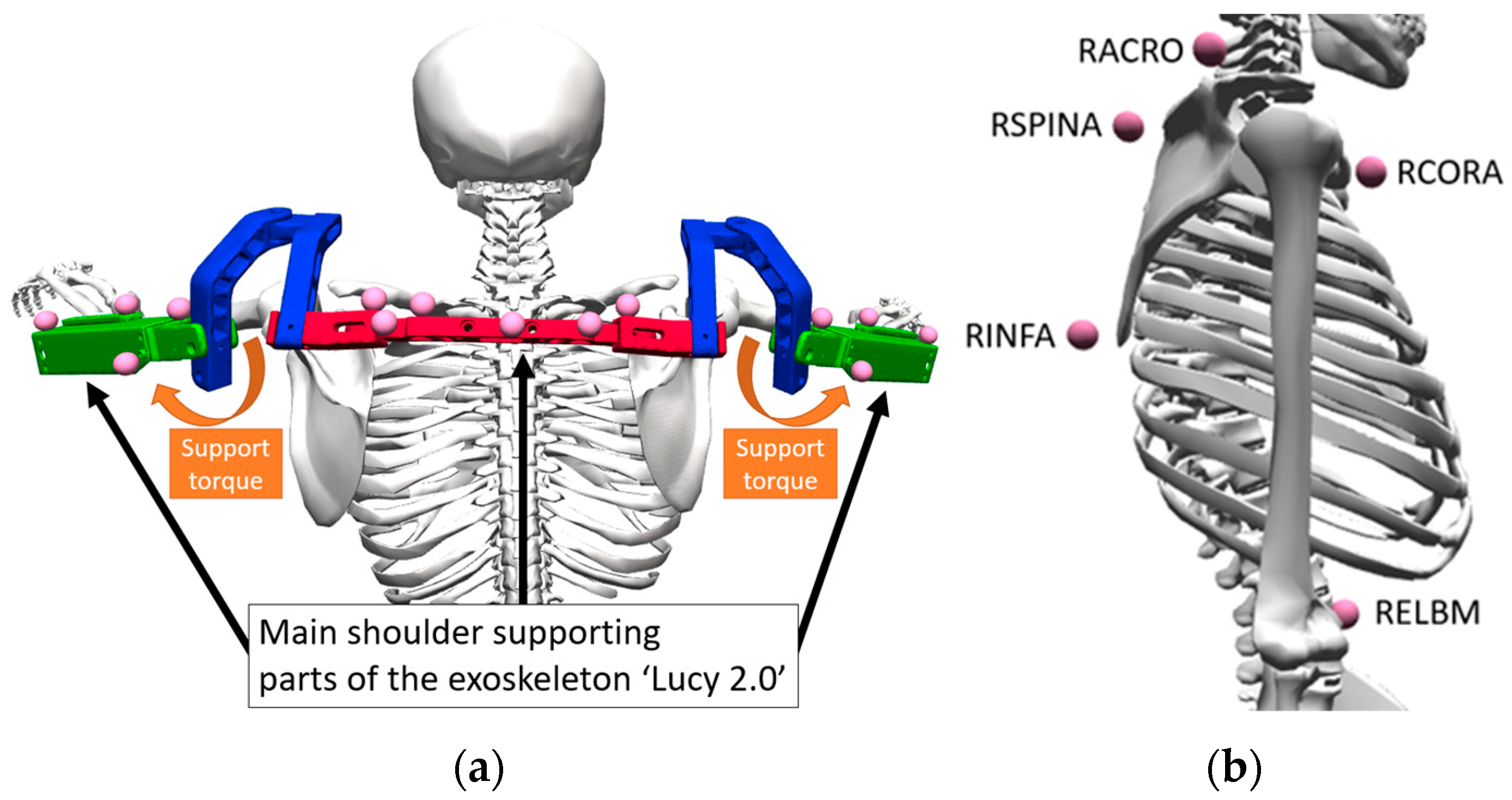
38] to integrate the exoskeleton geometry and kinematic chain, which is shown in
Figure 2a. The exoskeleton geometry objects in OpenSim 4.3 were used for external force orientation to define the interaction of the exoskeleton interface with the human humerus. The exoskeleton ‘Lucy 2.0’ [
39], used for this study, is colored in three functional areas, shown in
Figure 2a: the main part (red) of the exoskeleton attached to the human’s thorax (5 markers attached); the exoskeleton–upper arm interface (green, 4 markers on each side); the exoskeleton shoulder parts (blue) that allow a kinematic chain in non-supporting DOFs. The additional markers were also placed on the active shoulder exoskeleton [
39] to ensure accurate motion synchronization between the human and the assistive device. Otten et al. [
39] provide a detailed description of the active exoskeleton ‘Lucy 2.0’ for shoulder support. The exoskeleton is pneumatically driven and has two degrees of freedom (DOF) per side, one of them non-actuated. For the adjustment of the level of the support, the user can use the integrated control element. The main shoulder kinematic is illustrated in
Figure 2a.
A 14-camera optical motion capture system (sampling rate of 250 Hz, VICON, Oxford, UK) with the Vicon Nexus software v2.12 (VICON, Oxford, UK) was used to track the human movement. The marker set was based on the Plug-in Gait Marker Set [
40] (39 markers) with six additional markers placed on the scapula and humerus for enhanced tracking of shoulder kinematics. The additional markers on the scapula and the humerus are shown in
Figure 2b. The markers were named and attached to the following anatomical landmarks: RACRO (right Acromion), RCORA (right Coracoid), RSPINA (right spina scapulae), RINFA (right angulus inferior) and RELBM (right elbow medial).
The marker data was imported into OpenSim’s IK simulation via a C3D file.
2.2. Exoskeleton Support Model
The empirical “exoskeleton support model” was described in Reimeir et al. [
10]. The “exoskeleton support model” was used to simulate the mechanical properties of exoskeletons, illustrated with an active shoulder supportive exoskeleton in [
39], based on the measured support torque from a test rig.
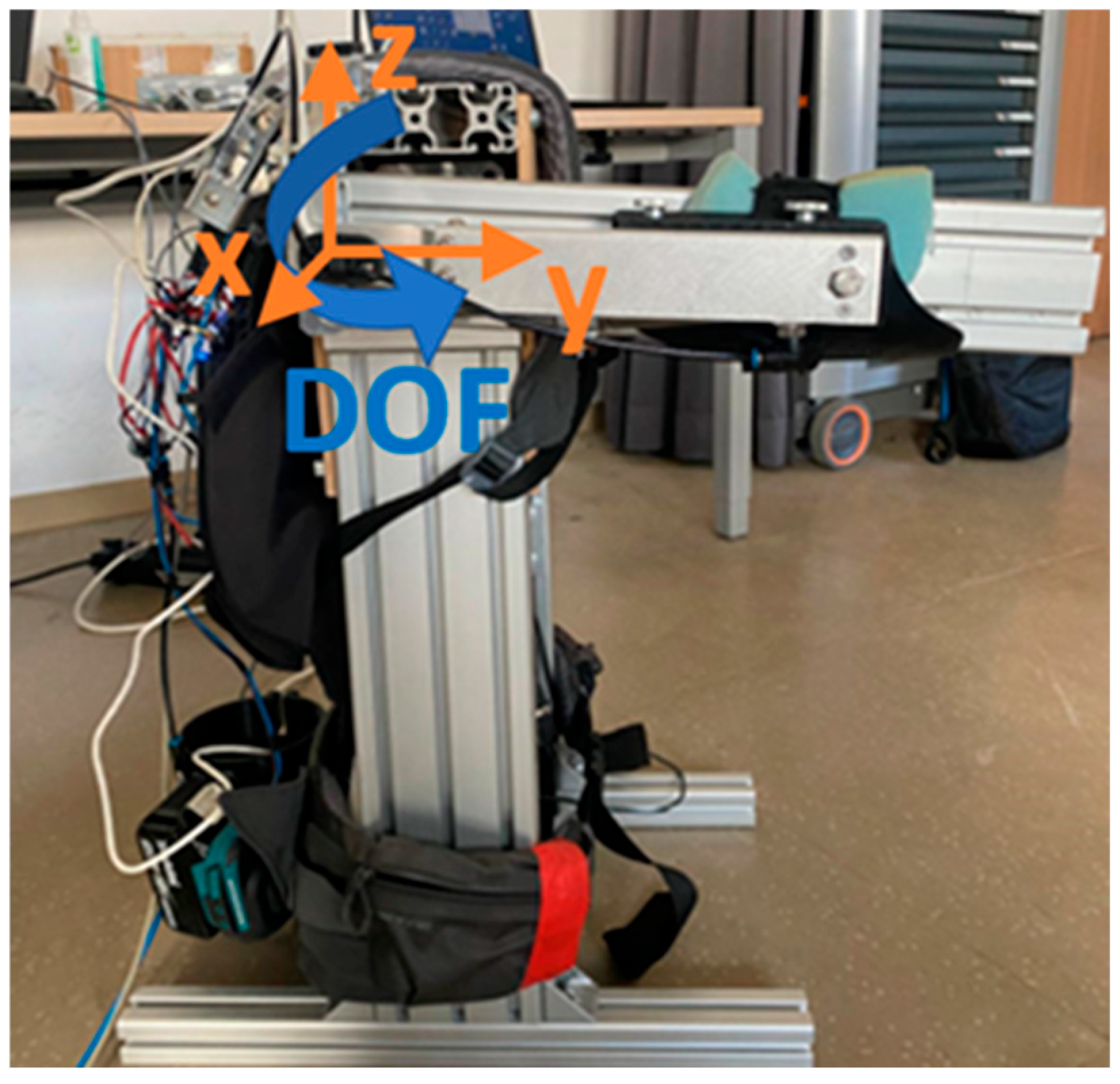
Figure 3 shows the test rig with one driven joint and standardized frame used to measure the experimental support torque (
) during the measurement of an active exoskeleton depending on the input exoskeleton elevation angle (
) and velocity (
):
This test rig measures the torque generated by the exoskeleton around the support joint axis by varying the elevation angle (
; 0–135°) and elevation angular velocity (
; 5°/s, 15°/s, 30°/s, 45°/s, 60°/s, 75°/s, 90°/s, 120°/s, 150°/s, 180°/s) around the x-axis. The experiment was repeated 5 times for each angular velocity (
). A detailed description of the test rig is described in Dangel et al. [
32].
To simulate exoskeleton support, an external force (
) was applied to the humerus in OpenSim 4.3. The interaction points and force direction depend on the position of the exoskeleton’s green part (
) in
Figure 2a.
To generate an empirical model of the exoskeleton’s support torque, the measured data from the test rig (including support torques, angles and angle velocities) was imported into MATLAB R2023a [
10]. The experimental data was fit with the cubic smoothing spline fitting algorithm “csaps” in MATLAB R2023a [
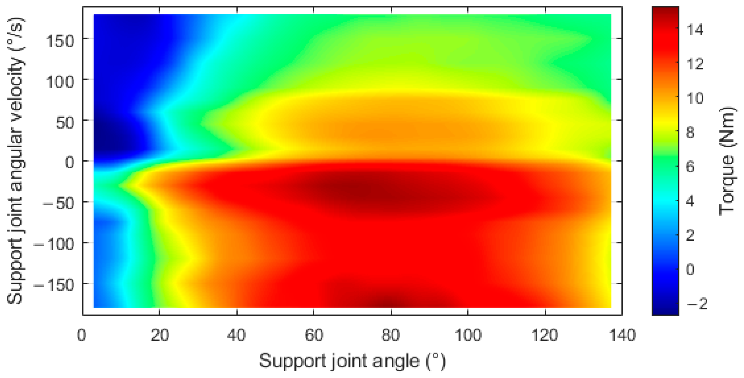
41]. This algorithm returns a spline in the form of a piecewise polynomial (SPP) that represents the support torque model. SPP returns the support torque depending on the support joint angle (
) and support joint angular velocity (
). The graphical representation of the “Exoskeleton support model” fitted by the multidimensional cubic smoothing spline (csaps) is shown in
Figure 4.
2.3. Muscle Optimization
In most cases, the static optimization tool in OpenSim is used to calculate muscle activations. However, when performing the static optimization with the model, the parallel elastic elements were too sensitive at high flexion angles (up to 140° flexion and 75° glenohumeral angle), resulting in unrealistic muscle forces. This effect may be due to the muscle paths of the OpenSim ‘Arm Swing Model’ [
35,
42], which were developed based on cadaver testing at glenohumeral angles of up to 60° [
43,
44] and scapula elevation kinematics at flexion angles of up to 150° [
45]. Therefore, only the forces due to the contractile element were considered and the serial elastic element was neglected. Thus, muscle optimization had to be calculated outside OpenSim 4.3.
To evaluate the muscle activation, a MATLAB code was written using the OpenSim API. The OpenSim API was used to obtain information about muscle fiber length (
), muscle moment arms (
), muscle maximum isometric force (
) and the muscle shortening velocity (
). To calculate muscle activation, an objective function was defined. This objective function uses the Hill-type models’ [
46] contractile element to calculate the muscle forces of the current frame.
The objective function included the external joint moment () for each rotational coordinate (j) from the ID and the following muscles: deltoideus anterior, deltoideus middle, deltoideus posterior, supraspinatus, infraspinatus, subscapularis, teres minor, teres major, pectoralis major, latissimus dorsi, coracobrachialis, triceps brachii long head, biceps brachii long head, biceps brachii short head. For each of these muscles (m), activation () was calculated by the fmincon algorithm in MATLAB R2023a using the interior point method to minimize the objective function. (Additional information about the MATLAB optimization solver settings: MaxIter = 15; DiffMinChange = 0.0001; ObjectiveLimit = 0.01).
Equations (2) and (3) show the mathematical formulation of the optimization problem with the objective function (J, minimal effort) fulfilling Condition (3) [
47]. The value
describes the moment arm of each muscle (
m) and its rotational coordinate (
j):
2.4. Joint Reaction Analysis
To determine the JRFs (
), an equilibrium around the glenohumeral joint was formulated. The resultant JRF was then transformed into the geometry of a glenohumeral joint finite-element model [
48], as described by Labriola et al. [
49]. The compressive JRF acts perpendicularly to the glenohumeral sagittal plane, while the tangential JRF (
) is the resulting force within the glenohumeral sagittal plane. For a better understanding, an illustration can be found in Figure 12 in
Section 4.3. To calculate the JRFs (
) for each translational coordinate (
k), Equation (4) is used. This equation depends on the external translational joint forces (
) from the ID and the sum of the muscle forces (
) multiplied by their coordinate fractions (
):
3. Validation and Application
An exemplary movement with and without exoskeleton was captured using a marker-based motion capture system and analyzed with the musculoskeletal simulation pipeline. To validate the results, the simulated excitation was compared with the measured excitation from the EMG. The use case was performed with one young, healthy male subject (1.89 m, 91.1 kg).
3.1. Use Case
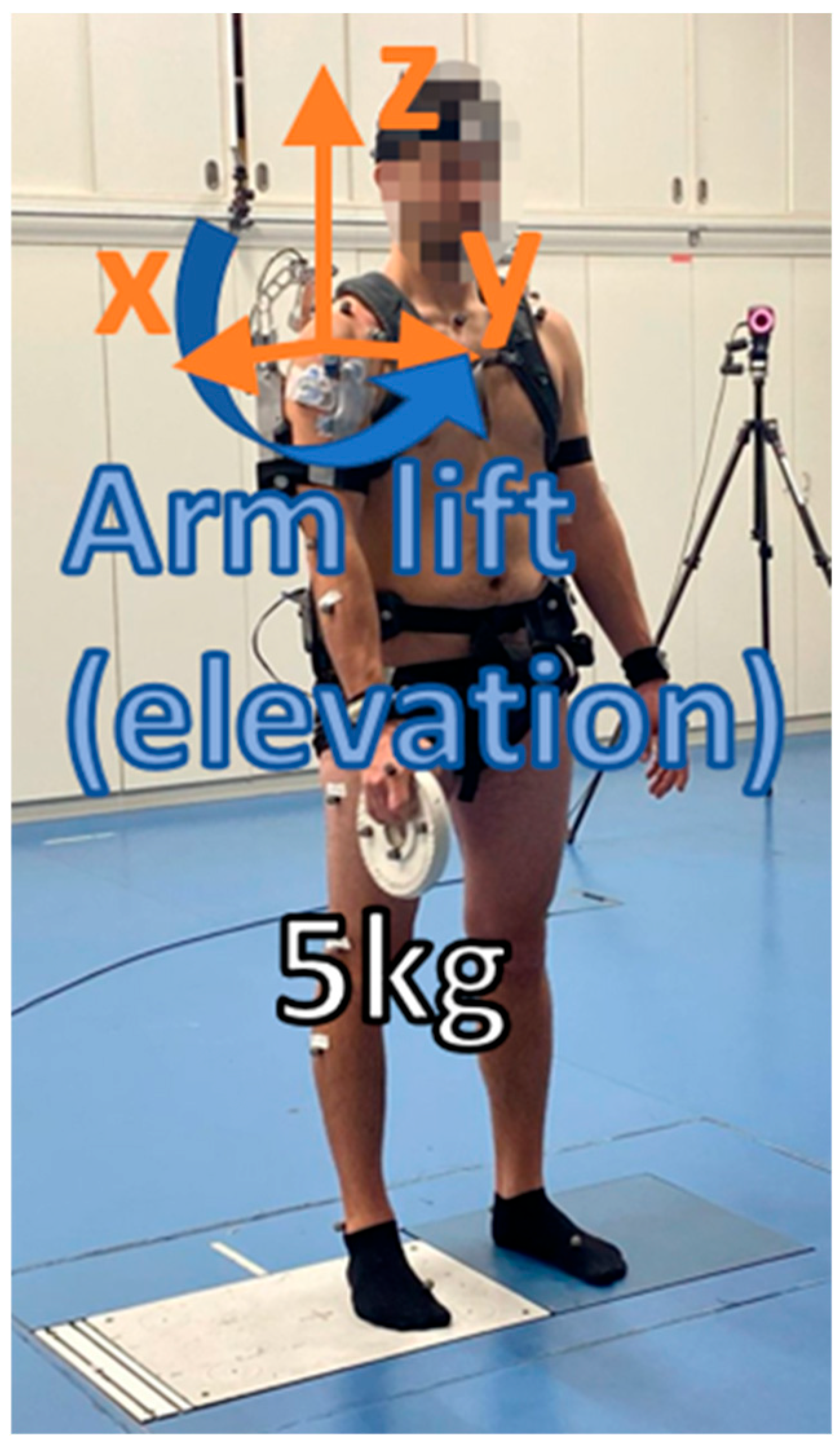
For this use case, the task was to lift a 5 kg weight with the right arm, moving it along the shoulder elevation in the sagittal plane. The shoulder elevation covered the whole support range of the exoskeleton (0° < shoulder elevation < 120°). This movement was repeated five times with and without exoskeleton.
Figure 5 shows the experimental setup. The test subject is standing on a separate force plate with each foot, wearing an active shoulder exoskeleton, and holding a 5 kg weight in the right hand. The elevation angle is illustrated around the x-axis.
This experimental setup was designed to validate the usability of the musculoskeletal simulation pipeline to simulate dynamic overhead tasks. The exoskeleton was set to its maximum support level, just like in the test rig. The EMG signal, including a Maximum Voluntary Contraction (MVC) of six muscles, was measured according to SENIAM guidelines [
50].
3.2. Exoskeleton Support
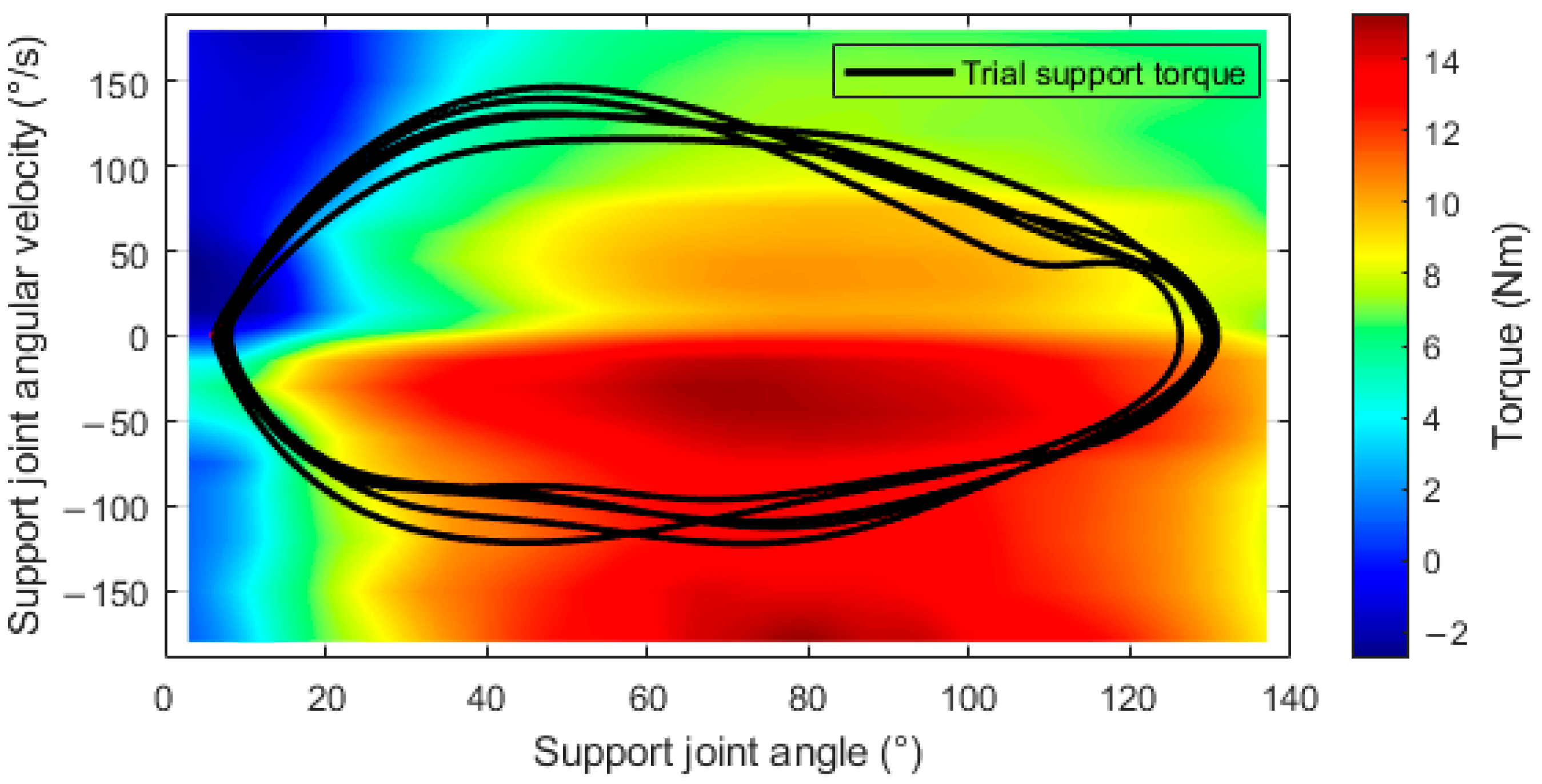
To calculate the supportive mechanical interactions between the exoskeleton and the upper arm, the “Exoskeleton support model” was used. The exoskeleton’s support torque was determined depending on the support joint angle and angular velocity, as is shown in
Figure 6. The trajectories in this space describe the temporal evolution of shoulder motion during a movement task. The model computes the assistive torque generated by the exoskeleton for every admissible state, thereby mapping the mechanical interaction between the user and the device across the entire operational range. Five cycles of arm elevation were performed while wearing the exoskeleton. The exoskeleton’s support joint angle and angular velocity were calculated with IK and used as input for the support torque model. The curve “Trial support torque” shows the output (exoskeleton support torque) of the “Exoskeleton support model” regarding the five cycles of arm elevation.
3.3. EMG vs. Muscle Simulation
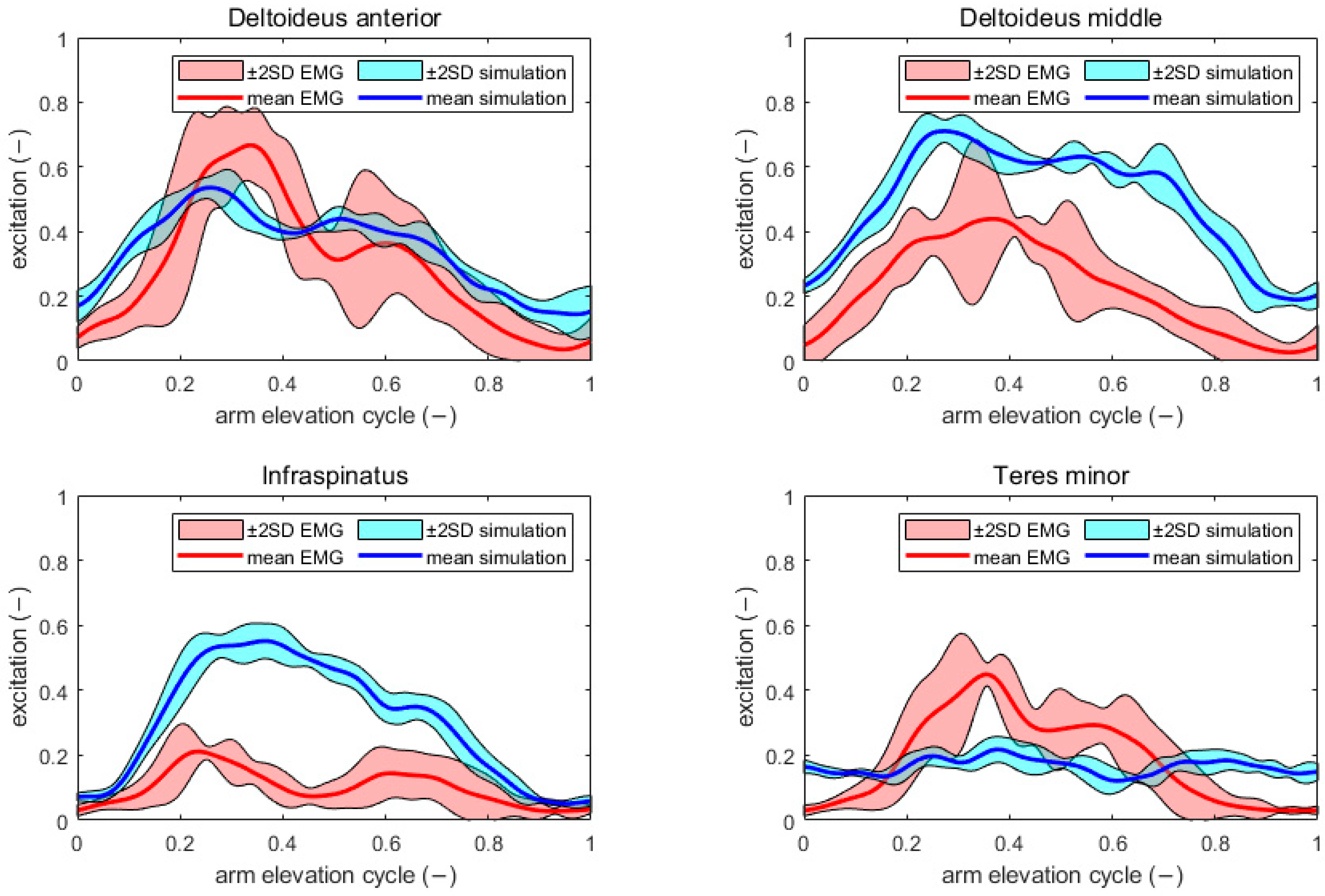
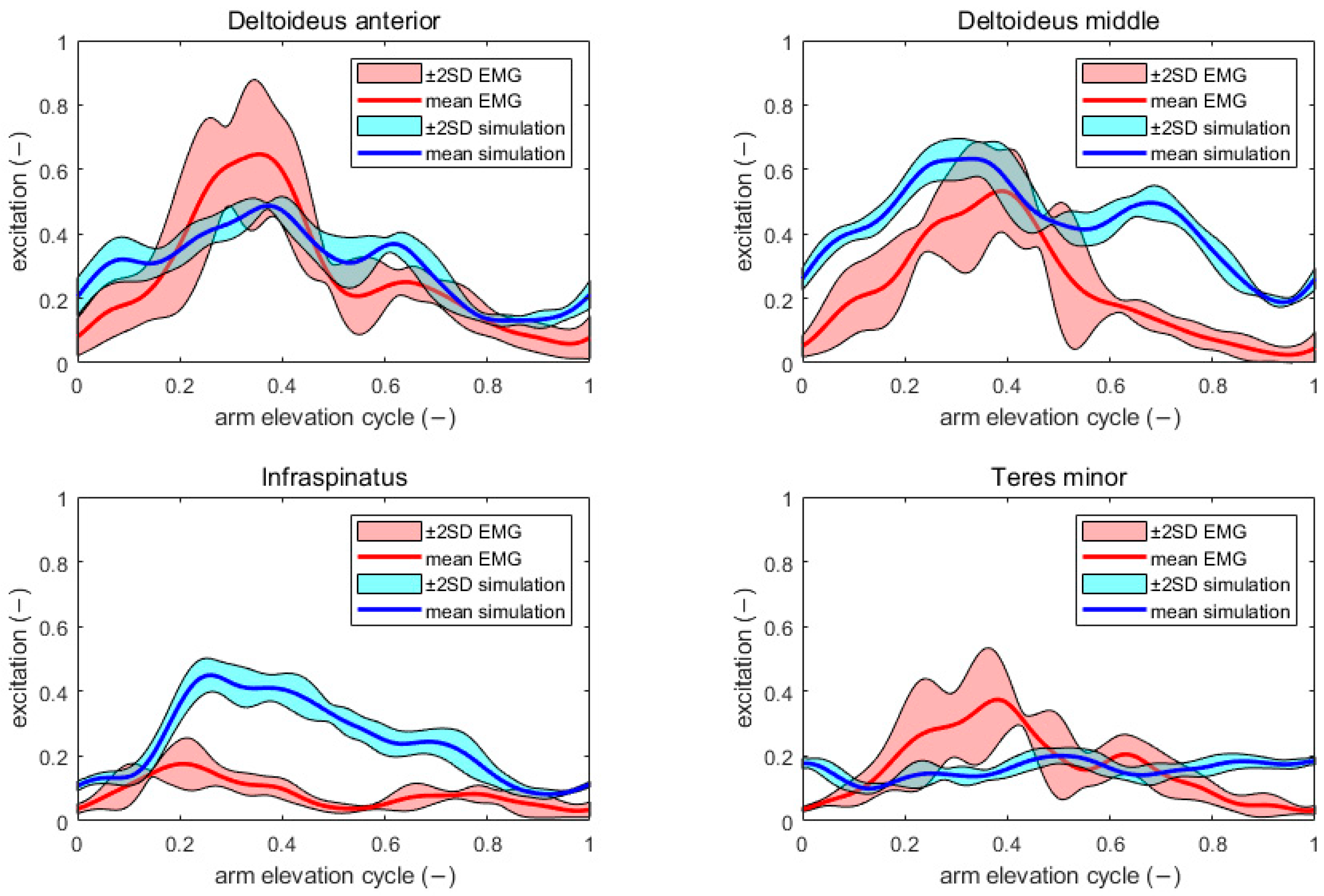
EMG data for four muscles (anterior and middle deltoid, teres minor, and infraspinatus) was collected from the approaches with and without exoskeleton. To compare the EMG results with results from the muscle optimization, each EMG signal (with a sampling rate of 2000 Hz and filtered with a 2 Hz low-pass filter) was normalized using the peak muscle activation of the reference MVC measurement. Comparisons of the normalized EMG signal to the muscle optimization excitation for each measured muscle are shown in
Figure 7 and
Figure 8. The excitation was computed with MATLAB R2023a and the OpenSim API, for extracting the geometric information of each frame from the OpenSim model. The mean absolute error (MAE) between muscle excitation from EMG and muscle excitation from the simulation was calculated for tasks performed with and without an exoskeleton. The average MAE for muscle excitation without an exoskeleton was 0.1415, compared to 0.1141 with an exoskeleton.
Equation (5) shows the differential relationship of activation (
) and an excitation (
), which was used in the simulation pipeline [
46,
51]. The activation rate constants (
and
) were taken from the “Arm Swing Model” (c
1 = 75, c
2 = 25) [
35]:
4. Results
The following results summarize shoulder external joint torques, muscle activation areas under the curve (EMG and simulations), glenohumeral joint reaction forces, and tangential JRF directions during five arm elevation cycles performed by one subject with and without the exoskeleton.
4.1. External Joint Torque
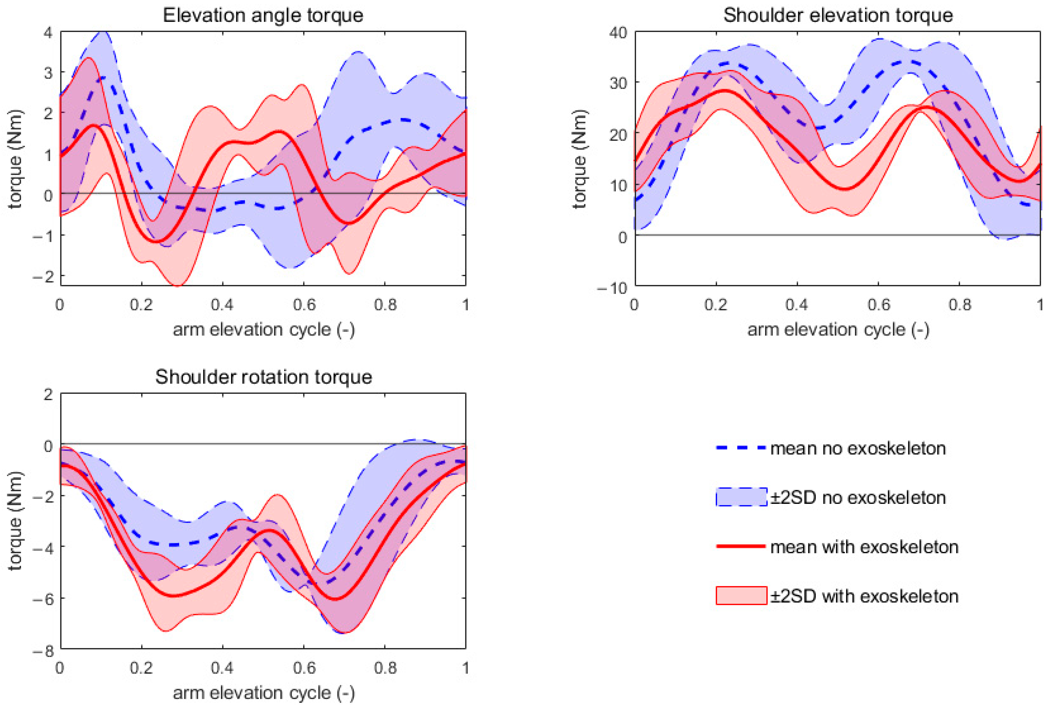
External joint torques of the shoulder, during the use case tasks, were computed with the OpenSim APIs ID in MATLAB R2023a (step 3), based on the results from step 1 and step 2. The external joint torques of the right shoulder with and without exoskeleton are shown in
Figure 9. Five cycles of arm elevation movement with a 5 kg weight were performed during the use case. Joint torques of each cycle were taken and scaled to an interval between 0 and 1. The mean torque of all five arm elevation cycles (with and without exoskeleton) and its two standard deviation boundaries are shown in
Figure 9. Wearing the exoskeleton decreases shoulder elevation torque by an average of 4.66 Nm.
4.2. Area Under the Curve
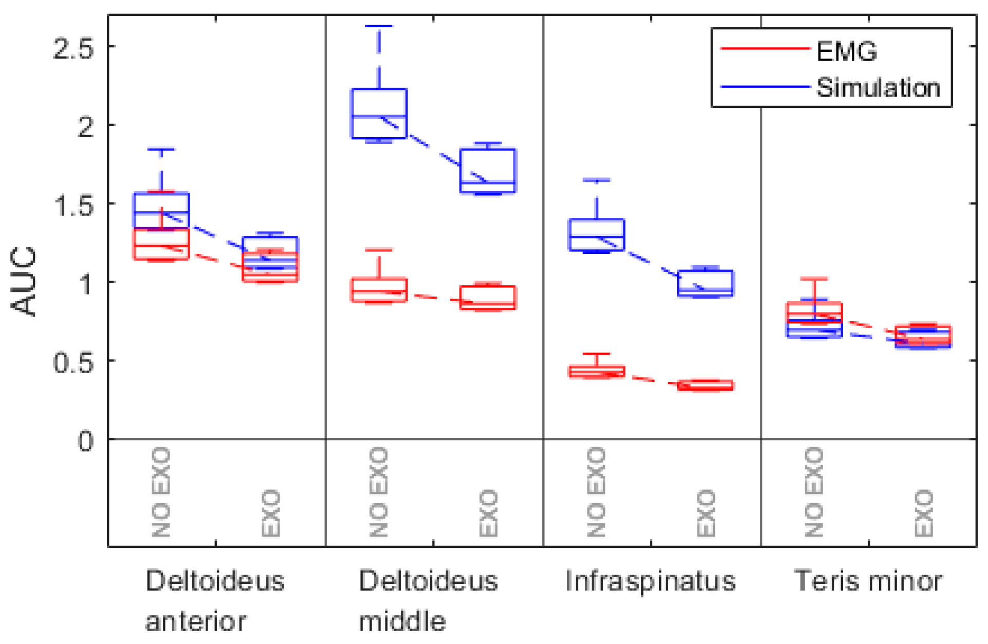
The area under the curve (AUC) was used to compare the EMG data and simulation results. The AUC of each measured muscle was calculated from the normalized EMG signal over time and simulated muscle excitation over time. The comparison of the AUC with and without exoskeleton is shown in
Figure 10. One boxplot shows the area under the curve for muscle excitations over time (of 5 arm elevation cycles intervals) for each muscle. Each muscle is described by four boxplots, where two are measured (EMG) and two are simulated.
4.3. Joint Reaction Forces in the Glenohumeral Joint
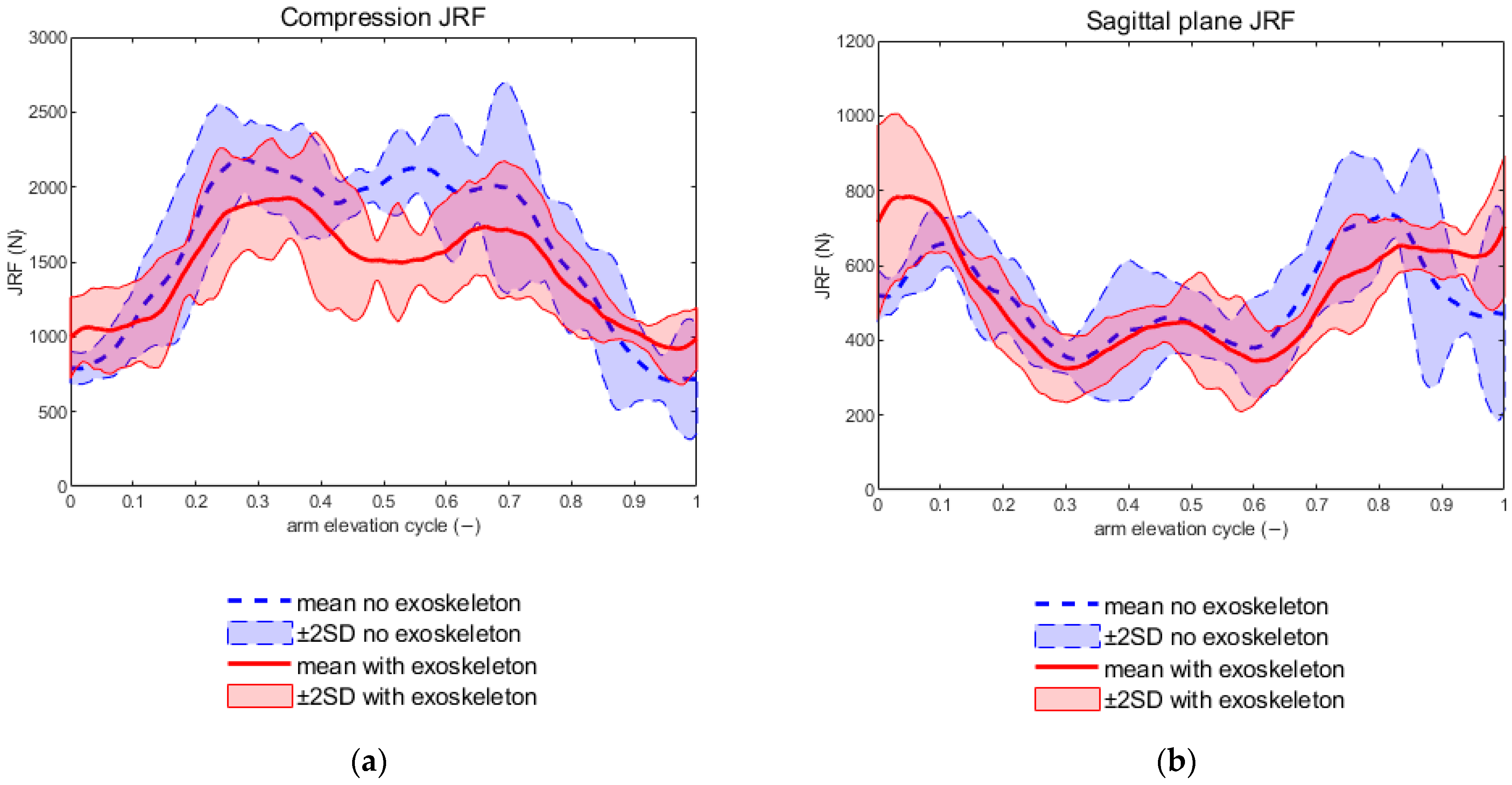
Figure 11a shows a reduction in the compressive JRF when wearing the exoskeleton. However, the average resulting sagittal plane JRF, shown in
Figure 11b, is 416.58 N without the exoskeleton and 426.65 N with the exoskeleton.
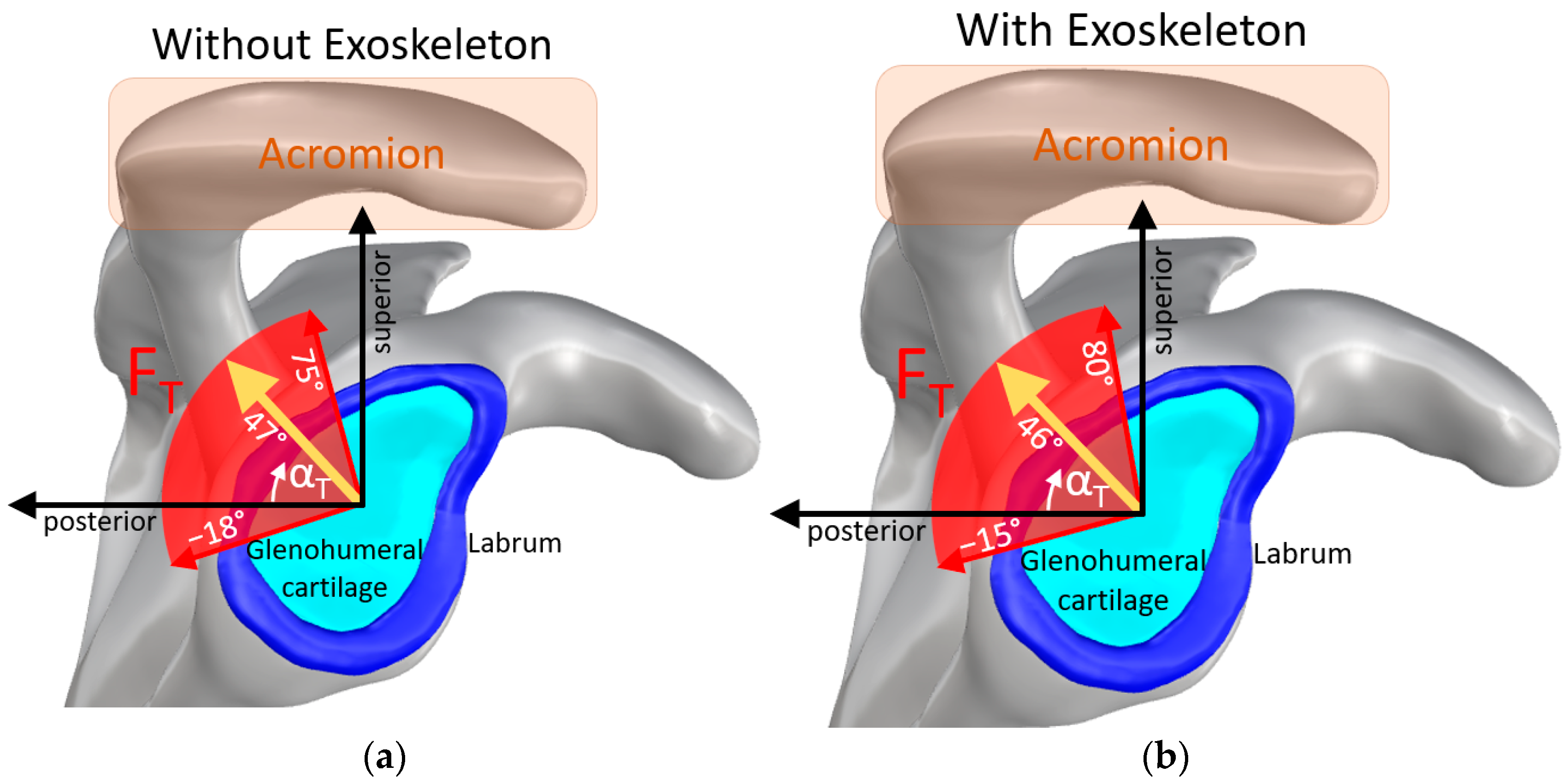
Figure 12 shows the direction of action of the JRF tangential component F
T in the sagittal plane of the glenohumeral joint. The value α
T shows the angle between the tangential JRF and the posterior axis. The simulation without an exoskeleton shows a mean α
T of 47° and a range of 93°, while the simulation with an exoskeleton shows a mean α
T of 46° and a range of 95°. In
Figure 12, two soft tissues of the glenohumeral joint are shown in blue (labrum) and turquoise (glenohumeral cartilage). The acromion is shown on top of the figure. The average direction of F
T is shown by the yellow arrow in the glenohumeral joint.
5. Discussion
In this work, a musculoskeletal simulation pipeline was presented to evaluate the biomechanical effects of exoskeletons during movement. This progress not only accelerates the design process but also provides a safer and more cost-effective alternative to traditional user testing, particularly for extreme or risky configurations. Simulations do not replace necessary user tests, but they can reduce the number of user tests required.
5.1. Test Bench
The exoskeleton test bench plays a crucial role in generating accurate input data for the “exoskeleton support model” [
32], especially to investigate the mechanical properties of commercial exoskeletons (non-publicly available mechanical properties). The “exoskeleton support model” provides a reliable foundation for modeling the behavior of passive and active exoskeletons by measuring mechanical properties such as support torques, joint angles, and angular velocities [
10].
5.2. Effect of Exoskeleton Support Implementation Accuracy
The presented approach enables the determination of joint torques during locomotion wearing an exoskeleton. In the application examples, the joint torques in the shoulder have been determined when lifting a 5 kg weight. On average, the exoskeleton provides 7.75 Nm of support torque, while the decrease in shoulder elevation torques average is only 4.66 Nm. This shows that transferring only the support torque to the shoulder would be an oversimplification, overestimating the support by 66%.
Figure 9 also shows that the reduction in shoulder elevation torque is greater during the middle part of the arm elevation cycle (0.2–0.8), when the shoulder is under higher load.
Thinking of accuracy raises the issue of sensitivity according to changes in the input values. For further research, a sensitivity analysis of parameters, such as the location of the interaction point (at the exoskeleton interface) and direction of the support force, is recommended to further prove the reliability of the pipeline.
5.3. Area Under the Cure and Electromyography
Regarding the investigated task,
Figure 10 shows that the area under the curve (AUC) decreases for all four investigated muscles with the exoskeleton (simulated and measured). The AUC of the EMG signal reflects the cumulative level of muscle activation over time and is commonly used as an indicator of overall muscular effort during a task. Although it does not represent a direct measure of metabolic energy expenditure, a reduction in AUC suggests that the muscles required less overall activation to perform the movement [
52]. This result therefore indicates that the exoskeleton reduced the muscular demand on the shoulder during the task.
Comparisons between simulated muscle excitations and electromyography (EMG) data demonstrate an acceptable degree of accuracy, with an RMSE for AUC of 37%. Aligning the simulated excitation with the measured EMG yields an average MAE of 0.14 without the exoskeleton and 0.11 with it. Belli et al. [
53] report an average MAE of only 0.06 between EMG measurements and simulated muscle excitation. However, it should be noted that the higher load of 5 kg during the arm elevation task compared to the 2 kg used by Belli et al. results in higher muscle excitations and, consequently, higher absolute errors.
5.4. Comparison of Results with the Literature
The results can only be compared to the literature to a limited extent, as Yan et al. [
54] conducted a static experiment and Zhou et al. [
30] used both hands for the lifting task. In both experiments, different exoskeletons were used than in our experiment. Nevertheless, we attempted to compare the decrease in AUC and the resulting JRF with the results using what we considered to be the most suitable studies [
30,
54].
Yan et al. [
54] validated an upper limb prototype exoskeleton with different support characteristics using EMG on various shoulder muscles. The integrated electromyography (IEMG) during a static lifting task with a 4.5 kg weight was calculated with and without exoskeleton support. Wearing an upper limb exoskeleton resulted in a 38% decrease in the IEMG of the deltoideus muscle, whereas, in this study, the AUC, which is comparable to IEMG, of the deltoideus decreased by only 13%. However, the AUC of the deltoideus resulting from the musculoskeletal simulation showed a 21% reduction when wearing an exoskeleton.
The maximum magnitude JRF is 2331.72 N without exoskeleton and 2118.13 N with exoskeleton. In Zhou et al. [
30], the JRFs during the lifting of a 10 kg box using both arms were simulated. Assuming the weight force was divided equally between both hands, the results in Zhou et al. [
30] show a 21% greater maximum magnitude JRF.
5.5. Loading of the Subacromial Space
One critical concern in overhead tasks are injuries in the glenohumeral joint, especially in the subacromial space [
15]. This issue is particularly relevant for exoskeletons designed to assist with overhead tasks. The simulation pipeline described in this study offers a valuable tool for addressing this challenge.
More specifically, the geometry of a finite-element model [
48] is used to calculate the force components (tangential force and compression force). The compressive force in the glenohumeral joint decreases when the exoskeleton is worn. However, the JRF in the sagittal plane remains roughly the same. In order to understand the actual effects of exoskeletons on the subacromial space, a study involving several test subjects must be conducted.
According to Dickerson et al. [
55], the subacromial space decreases due to the fatigue of the shoulder muscles at high shoulder elevation angles. However, muscle fatigue is not taken into account in this study, so this effect cannot be considered. Integrating muscle fatigue into the simulation pipeline could be an important contribution, especially in the development of occupational exoskeletons.
5.6. Limitations
The use of data from only one subject limits the generalizability of the findings. Inter-individual variability in anatomy and muscle activation could lead to different outcomes in a broader population. Additional subjects are necessary, especially for statements about loading on the subacromial space.
The simulation focuses exclusively on shoulder muscles, neglecting the potential contributions of trunk and other upper body muscles. This localized approach may overlook important interactions that could influence the overall biomechanical effects of the exoskeleton.
By considering only the contractile elements of the muscle-tendon unit, the model neglects the passive elastic components. This can lead to inaccuracies at the limits of the shoulder’s range of motion. On the other hand, an incorrect assumption about the elastic components can lead to inaccurate muscle forces. This led us to the decision to only simulate with the contractile element.
6. Conclusions
This paper presents a fully integrated musculoskeletal simulation pipeline for evaluating exoskeletons with the example of shoulder exoskeletons during overhead tasks. The combination of a MATLAB-based workflow, OpenSim-based musculoskeletal modeling, and empirical exoskeleton support data represents a novel approach that allows a rapid, reproducible, and quantitative assessment of joint loads, muscle activations, and potential subacromial space stress. Key findings include the following:
- -
The pipeline predicts joint reaction forces and muscle activity, with EMG validation showing acceptable agreement;
- -
Use of the exoskeleton reduces shoulder effort and compressive forces, highlighting its potential to improve user safety and reduce fatigue during overhead tasks;
- -
Quantitative comparison with the existing literature demonstrates that the approach can detect nuanced changes in load distribution and provides finer insights than studies relying only in EMG or simplified models.
Importantly, the pipeline enables a direction-specific analysis of joint reaction forces. This is a critical step toward evaluating subacromial space loading, a factor that was not addressed in prior simulation studies. This provides a foundation for guiding exoskeleton design toward both performance enhancement and long-term joint protection.
Future work should focus on including multi-subject validation to account for inter-individual variability. The pipeline could also be applied to long-term studies to simulate prolonged or repetitive work, as well as to comparative studies of multiple passive and active exoskeletons to optimize mechanical support and minimize subacromial stress.
Overall, this work establishes a quantitative, simulation-driven framework that bridges the gap between exoskeleton design and biomechanical safety assessment, paving the way for more effective, user-centered exoskeletons in occupational and rehabilitation settings.
Author Contributions
Conceptualization M.E., R.W. and R.E.; software, M.E. and B.R.; validation, M.E., R.E., B.R. and D.S.; writing—original draft, M.E. and D.S.; writing—review and editing, M.E., R.E., D.S., B.R. and R.W.; funding acquisition, R.W.; supervision, R.W. and R.E. All authors have read and agreed to the published version of the manuscript.
Funding
This research paper [project EVO-MTI] is funded by dtec.bw—Digitalization and Technology Research Center of the Bundeswehr. dtec.bw is funded by the European Union—NextGenerationEU.
Institutional Review Board Statement
The experimental evaluation was performed with one young, healthy male subject (1.89 m, 91.1 kg), who was a member of the research group and author of this study. The participant provided informed consent prior to data collection. Since the measurements involved a self-experiment conducted by an author without external participants, the study was exempt from formal ethics committee approval, in accordance with institutional guidelines.
Informed Consent Statement
Informed consent was obtained from all subjects involved in the study.
Data Availability Statement
The original contributions presented in the study are included in the article; further inquiries can be directed to the corresponding author.
Conflicts of Interest
The authors declare no conflicts of interest.
References
- Yao, Z.; Mir Latifi, S.M.; Molz, C.; Scherb, D.; Löffelmann, C.; Sänger, J.; Miehling, J.; Wartzack, S.; Lindenmann, A.; Matthiesen, S.; et al. A Novel Approach to Simulating Realistic Exoskeleton Behavior in Response to Human Motion. Robotics 2024, 13, 27. [Google Scholar] [CrossRef]
- Molz, C.; Scherb, D.; Löffelmann, C.; Sänger, J.; Yao, Z.; Lindenmann, A.; Matthiesen, S.; Weidner, R.; Wartzack, S.; Miehling, J. A Co-Simulation Model Integrating a Musculoskeletal Human Model with Exoskeleton and Power Tool Model. Appl. Sci. 2024, 14, 2573. [Google Scholar] [CrossRef]
- Flor-Unda, O.; Casa, B.; Fuentes, M.; Solorzano, S.; Narvaez-Espinoza, F.; Acosta-Vargas, P. Exoskeletons: Contribution to Occupational Health and Safety. Bioengineering 2023, 10, 1039. [Google Scholar] [CrossRef]
- Bär, M.; Steinhilber, B.; Rieger, M.A.; Luger, T. The Influence of Using Exoskeletons during Occupational Tasks on Acute Physical Stress and Strain Compared to No Exoskeleton—A Systematic Review and Meta-Analysis. Appl. Ergon. 2021, 94, 103385. [Google Scholar] [CrossRef]
- Rodriguez-Fernandez, A.; Lobo-Prat, J.; Font-Llagunes, J.M. Systematic Review on Wearable Lower-Limb Exoskeletons for Gait Training in Neuromuscular Impairments. J. Neuroeng. Rehabil. 2021, 18, 1–21. [Google Scholar] [CrossRef]
- Ma, T.; Zhang, Y.; Choi, S.D.; Xiong, S. Modelling for Design and Evaluation of Industrial Exoskeletons: A Systematic Review. Appl. Ergon. 2023, 113, 104100. [Google Scholar] [CrossRef]
- Niknezhad, S.; Goudarzi, A.M. Biomechanical Evaluation of Compliance Joint Knee Exoskeleton During Normal Gait. Int. J. Eng. 2024, 37, 2099–2108. [Google Scholar] [CrossRef]
- Sänger, J.; Wirth, L.; Yao, Z.; Scherb, D.; Miehling, J.; Wartzack, S.; Weidner, R.; Lindenmann, A.; Matthiesen, S. ApOL-Application Oriented Workload Model for Digital Human Models for the Development of Human-Machine Systems. Machines 2023, 11, 869. [Google Scholar] [CrossRef]
- Kenas, F.; Saadia, N.; Ababou, A.; Ababou, N. Model-Free Based Adaptive BackStepping-Super Twisting-RBF Neural Network Control with α-Variable for 10 DOF Lower Limb Exoskeleton. Int. J. Intell. Robot. Appl. 2024, 8, 122–148. [Google Scholar] [CrossRef]
- Reimeir, B.; Dangel, L.; Drees, T.; Ebenbichler, M.; Eberle, R.; Kuhlenkötter, B.; Weidner, R. Empirical Computational Models of Support Behavior for Active and Passive Occupational Exoskeletons. Wearable Technol. 2026; submitted. [Google Scholar]
- Seth, A.; Sherman, M.; Reinbolt, J.A.; Delp, S.L. OpenSim: A Musculoskeletal Modeling and Simulation Framework for in Silico Investigations and Exchange. Procedia IUTAM 2011, 2, 212–232. [Google Scholar] [CrossRef]
- Bodin, J.; Ha, C.; Petit Le Manac’h, A.; Sérazin, C.; Descatha, A.; Leclerc, A.; Goldberg, M.; Roquelaure, Y. Risk Factors for Incidence of Rotator Cuff Syndrome in a Large Working Population. Scand. J. Work. Environ. Health 2012, 38, 436–446. [Google Scholar] [CrossRef]
- van Rijn, R.M.; Huisstede, B.M.; Koes, B.W.; Burdorf, A. Associations between Work-Related Factors and Specific Disorders of the Shoulder—A Systematic Review of the Literature. Scand. J. Work. Environ. Health 2010, 36, 189–201. [Google Scholar] [CrossRef]
- Parsons, I.M.; Apreleva, M.; Fu, F.H.; Woo, S.L.Y. The Effect of Rotator Cuff Tears on Reaction Forces at the Glenohumeral Joint. J. Orthop. Res. Off. Publ. Orthop. Res. Soc. 2002, 20, 439–446. [Google Scholar] [CrossRef]
- Dickerson, C.R.; Brookham, R.L.; Chopp, J.N. The Working Shoulder: Assessing Demands, Identifying Risks, and Promoting Healthy Occupational Performance. Phys. Ther. Rev. 2011, 16, 310–320. [Google Scholar] [CrossRef]
- Yamamoto, M.; Shimatani, K.; Hasegawa, M.; Kurita, Y. Effect of an Ankle–Foot Orthosis on Gait Kinematics and Kinetics: Case Study of Post-Stroke Gait Using a Musculoskeletal Model and an Orthosis Model. ROBOMECH J. 2019, 6, 9. [Google Scholar] [CrossRef]
- Zhang, F.; Chen, J.; Wang, W.; Han, H.; Li, X.; Zhang, J. Optimization of Gait Assistance Pattern for Charcot-Marie-Tooth Patients Based on Forward Predictive Simulation. In Proceedings of the 2021 International Conference on Computer, Control and Robotics (ICCCR), Shanghai, China, 8–10 January 2021; pp. 199–203. [Google Scholar]
- Akbas, T.; Sulzer, J. Musculoskeletal Simulation Framework for Impairment-Based Exoskeletal Assistance Post-Stroke. In Proceedings of the 2019 IEEE 16th International Conference on Rehabilitation Robotics (ICORR), Toronto, ON, Canada, 24–28 June 2019; pp. 1185–1190. [Google Scholar]
- Afschrift, M.; De Groote, F.; De Schutter, J.; Jonkers, I. The Effect of Muscle Weakness on the Capability Gap during Gross Motor Function: A Simulation Study Supporting Design Criteria for Exoskeletons of the Lower Limb. Biomed. Eng. OnLine 2014, 13, 111. [Google Scholar] [CrossRef]
- Scherb, D.; Wartzack, S.; Miehling, J. Modelling the Interaction between Wearable Assistive Devices and Digital Human Models—A Systematic Review. Front. Bioeng. Biotechnol. 2023, 10, 1044275. [Google Scholar] [CrossRef]
- Farris, D.J.; Hicks, J.L.; Delp, S.L.; Sawicki, G.S. Musculoskeletal Modelling Deconstructs the Paradoxical Effects of Elastic Ankle Exoskeletons on Plantar-Flexor Mechanics and Energetics during Hopping. J. Exp. Biol. 2014, 217, 4018–4028. [Google Scholar] [CrossRef]
- Wu, Y.; Zhu, A.; Shen, H.; Shen, Z.; Zhang, X.; Cao, G. Biomechanical Simulation Analysis of Human Lower Limbs Assisted by Exoskeleton. In Proceedings of the 2019 16th International Conference on Ubiquitous Robots (UR), Jeju, Republic of Korea, 24–27 June 2019; pp. 765–770. [Google Scholar]
- Michaud, F.; Mouzo, F.; Lugrís, U.; Cuadrado, J. Energy Expenditure Estimation During Crutch-Orthosis-Assisted Gait of a Spinal-Cord-Injured Subject. Front. Neurorobot. 2019, 13, 55. [Google Scholar] [CrossRef]
- Fritzsche, L.; Galibarov, P.E.; Gaertner, C.; Bornmann, J.; Damsgaard, M.; Wall, R.; Schirrmeister, B.; Gonzalez-Vargas, J.; Pucci, D.; Maurice, P.; et al. Assessing the Efficiency of Exoskeletons in Physical Strain Reduction by Biomechanical Simulation with AnyBody Modeling System. WEARABLE Technol. 2021, 2, e6. [Google Scholar] [CrossRef]
- van der Have, A.; Rossini, M.; Rodriguez-Guerrero, C.; Rossom, S.V.; Jonkers, I. The Exo4Work Shoulder Exoskeleton Effectively Reduces Muscle and Joint Loading during Simulated Occupational Tasks above Shoulder Height. Appl. Ergon. 2022, 103, 103800. [Google Scholar] [CrossRef]
- Bianco, N.A.; Franks, P.W.; Hicks, J.L.; Delp, S.L. Coupled Exoskeleton Assistance Simplifies Control and Maintains Metabolic Benefits: A Simulation Study. PLoS ONE 2022, 17, e0261318. [Google Scholar] [CrossRef]
- Dembia, C.L.; Silder, A.; Uchida, T.K.; Hicks, J.L.; Delp, S.L. Simulating Ideal Assistive Devices to Reduce the Metabolic Cost of Walking with Heavy Loads. PLoS ONE 2017, 12, e0180320. [Google Scholar] [CrossRef] [PubMed]
- Chander, D.S.; Böhme, M.; Andersen, M.S.; Rasmussen, J.; Cavatorta, M.P. Simulating the Dynamics of a Human-Exoskeleton System Using Kinematic Data with Misalignment Between the Human and Exoskeleton Joints. In Computer Methods, Imaging and Visualization in Biomechanics and Biomedical Engineering II, Proceedings of the 17th International Symposium CMBBE and 5th Conference on Imaging and Visualization, Virtual, 7–9 September 2021; Tavares, J.M.R.S., Bourauel, C., Geris, L., Vander Slote, J., Eds.; Springer: Cham, Switzerland, 2022; Volume 38, pp. 65–73. [Google Scholar]
- Christensen, S.; Li, X.; Bai, S. Modeling and Analysis of Physical Human-Robot Interaction of an Upper Body Exoskeleton in Assistive Applications. Model. Identif. Control 2021, 42, 159–172. [Google Scholar] [CrossRef]
- Zhou, X.; Zheng, L. Model-Based Comparison of Passive and Active Assistance Designs in an Occupational Upper Limb Exoskeleton for Overhead Lifting. IISE Trans. Occup. Ergon. Hum. Factors 2021, 9, 167–185. [Google Scholar] [CrossRef]
- Tröster, M.; Budde, S.; Maufroy, C.; Andersen, M.S.; Rasmussen, J.; Schneider, U.; Bauernhansl, T. Biomechanical Analysis of Stoop and Free-Style Squat Lifting and Lowering with a Generic Back-Support Exoskeleton Model. Int. J. Environ. Res. Public. Health 2022, 19, 9040. [Google Scholar] [CrossRef] [PubMed]
- Dangel, L.; Reimeir, B.; Weidner, R. ExoPowerCheck: A Performance Test Bench to Measure Support Behavior of Exoskeletons with Single-DoF Support. In Proceedings of the Annals of Scientific Society for Assembly, Handling and Industrial Robotics, Rostock, Germany, 29–30 June 2023; Accepted; MHI: Rostock, Germany, 2023. [Google Scholar]
- van den Bogert, A.J.; Blana, D.; Heinrich, D. Implicit Methods for Efficient Musculoskeletal Simulation and Optimal Control. Procedia IUTAM 2011, 2, 297–316. [Google Scholar] [CrossRef]
- Chadwick, E.K.; Blana, D.; Kirsch, R.F.; van den Bogert, A.J. Real-Time Simulation of Three-Dimensional Shoulder Girdle and Arm Dynamics. IEEE Trans. Biomed. Eng. 2014, 61, 1947–1956. [Google Scholar] [CrossRef]
- Goudriaan, M.; Jonkers, I.; van Dieen, J.H.; Bruijn, S.M. Arm Swing in Human Walking: What Is Their Drive? Gait Posture 2014, 40, 321–326. [Google Scholar] [CrossRef]
- Schmid, S.; Connolly, L.; Moschini, G.; Meier, M.L.; Senteler, M. Skin Marker-Based Subject-Specific Spinal Alignment Modeling: A Feasibility Study. J. Biomech. 2022, 137, 111102. [Google Scholar] [CrossRef]
- Seth, A.; Hicks, J.L.; Uchida, T.K.; Habib, A.; Dembia, C.L.; Dunne, J.J.; Ong, C.F.; DeMers, M.S.; Rajagopal, A.; Millard, M.; et al. OpenSim: Simulating Musculoskeletal Dynamics and Neuromuscular Control to Study Human and Animal Movement. PLoS Comput. Biol. 2018, 14, 1–20. [Google Scholar] [CrossRef]
- TU Delft OpenSim Creator 0.5.14. Available online: https://www.opensimcreator.com/ (accessed on 20 February 2025).
- Otten, B.M.; Weidner, R.; Argubi-Wollesen, A. Evaluation of a Novel Active Exoskeleton for Tasks at or Above Head Level. IEEE Robot. Autom. Lett. 2018, 3, 2408–2415. [Google Scholar] [CrossRef]
- Vicon Motion Systems Limited Plug-In Gait Reference Guide. Available online: https://help.vicon.com/download/attachments/11378719/Plug-in%20Gait%20Reference%20Guide.pdf (accessed on 20 February 2025).
- MathWorks Inc. Csaps. Available online: https://de.mathworks.com/help/curvefit/csaps.html#f7-5467_sep_mw_11ef892b-7c0a-4cb9-a0ba-9331aa87539a (accessed on 21 February 2025).
- Holzbaur, K.R.S.; Murray, W.M.; Delp, S.L. A Model of the Upper Extremity for Simulating Musculoskeletal Surgery and Analyzing Neuromuscular Control. Ann. Biomed. Eng. 2005, 33, 829–840. [Google Scholar] [CrossRef]
- Hughes, R.E.; Niebur, G.; Liu, J.; An, K.-N. Comparison of Two Methods for Computing Abduction Moment Arms of the Rotator Cuff. J. Biomech. 1997, 31, 157–160. [Google Scholar] [CrossRef]
- Liu, J.; Hughes, R.E.; Smutz, W.P.; Niebur, G.; Nan-An, K. Roles of Deltoid and Rotator Cuff Muscles in Shoulder Elevation. Clin. Biomech. 1997, 12, 32–38. [Google Scholar] [CrossRef]
- de Groot, J.H.; Brand, R. A Three-Dimensional Regression Model of the Shoulder Rhythm. Clin. Biomech. 2001, 16, 735–743. [Google Scholar] [CrossRef] [PubMed]
- Zajac, F.E. Muscle and Tendon: Properties, Models, Scaling, and Application to Biomechanics and Motor Control. Crit. Rev. Biomed. Eng. 1989, 17, 359–411. [Google Scholar]
- Hicks, J. How Static Optimization Works. Available online: https://opensimconfluence.atlassian.net/wiki/spaces/OpenSim/pages/53089619/How+Static+Optimization+Works (accessed on 19 February 2026).
- Sadeqi, S.; Baumann, A.P.; Goel, V.K.; Lilling, V.; Sullivan, S.J.L. A Validated Open-Source Shoulder Finite Element Model and Investigation of the Effect of Analysis Precision. Ann. Biomed. Eng. 2023, 51, 24–33. [Google Scholar] [CrossRef]
- Labriola, J.E.; Jolly, J.T.; McMahon, P.J.; Debski, R.E. Active Stability of the Glenohumeral Joint Decreases in the Apprehension Position. Clin. Biomech. 2004, 19, 801–809. [Google Scholar] [CrossRef]
- Hermens, H.J.; Freriks, B.; Disselhorst-Klug, C.; Rau, G. Development of Recommendations for SEMG Sensors and Sensor Placement Procedures. J. Electromyogr. Kinesiol. 2000, 10, 361–374. [Google Scholar] [CrossRef] [PubMed]
- He, J.; Levine, W.S.; Loeb, G.E. Feedback Gains for Correcting Small Perturbations to Standing Posture. IEEE Trans. Autom. Control 1991, 36, 322–332. [Google Scholar] [CrossRef]
- Bigland-Ritchie, B.; Woods, J.J. Integrated EMG and Oxygen Uptake during Dynamic Contractions of Human Muscles. J. Appl. Physiol. 1974, 36, 475–479. [Google Scholar] [CrossRef] [PubMed]
- Belli, I.; Joshi, S.; Prendergast, J.M.; Beck, I.; Santina, C.D.; Peternel, L.; Seth, A. Does Enforcing Glenohumeral Joint Stability Matter? A New Rapid Muscle Redundancy Solver Highlights the Importance of Non-Superficial Shoulder Muscles. PLoS ONE 2023, 18, 1–19. [Google Scholar] [CrossRef]
- Yan, Z.; Yi, H.; Du, Z.; Huang, T.; Han, B.; Zhang, L.; Peng, A.; Wu, X. Development of An Assist Upper Limb Exoskeleton For Manual Handling Task. In Proceedings of the 2019 IEEE International Conference on Robotics and Biomimetics (ROBIO), Dali, China, 6–8 December 2019; pp. 1815–1820. [Google Scholar]
- Dickerson, C.R.; McDonald, A.C.; Chopp-Hurley, J.N. Between Two Rocks and in a Hard Place: Reflecting on the Biomechanical Basis of Shoulder Occupational Musculoskeletal Disorders. Hum. Factors 2023, 65, 879–890. [Google Scholar] [CrossRef] [PubMed]
| Disclaimer/Publisher’s Note: The statements, opinions and data contained in all publications are solely those of the individual author(s) and contributor(s) and not of MDPI and/or the editor(s). MDPI and/or the editor(s) disclaim responsibility for any injury to people or property resulting from any ideas, methods, instructions or products referred to in the content. |




 ,
,