Article

Mechanism of Water Inrush Induced by Gob Water Under Repeated Mining and Control Technology Based on Roof Cutting Pressure Relief


1
School of Mines, China University of Mining and Technology, Xuzhou 221116, China
2
Shendong Tianlong Group Huoluowan Coal Mine, Ordos 750306, China
3
Pingdingshan Tianan Coal Mining Co., Ltd., Pingdingshan 467099, China
*
Author to whom correspondence should be addressed.
Appl. Sci. 2026, 16(4), 1970; https://doi.org/10.3390/app16041970
Submission received: 4 January 2026 / Revised: 3 February 2026 / Accepted: 10 February 2026 / Published: 16 February 2026
(This article belongs to the Special Issue Mechanics, Damage Properties and Impacts of Coal Mining, 2nd Edition)

Abstract

To mitigate the threat posed by accumulated gob water to underlying coal seams during multi-seam mining, this study investigates the mechanism of water inrush induced by repeated mining and its control through roof cutting pressure relief. The 31110 panel of the Holowan Coal Mine is taken as an engineering case, where the 3−1 coal seam is threatened by gob water from the overlying 2−2 coal seam. The mechanisms of interlayer rock mass damage accumulation, fracture interconnection, and water-conducting channel formation were systematically analyzed using a combination of theoretical analysis, numerical simulation, and field tests. The results indicate that the superimposed mining-induced failure zones of the upper and lower coal seams significantly exceed the interlayer spacing of 46.5 m. This condition promotes through-going damage of the interlayer strata and facilitates the downward migration of gob water. Without roof cutting, the main roof fractures toward the solid coal side of the 31110 auxiliary headgate, resulting in full connectivity of the overburden plastic zones and the formation of a continuous water-conducting channel. Roof cutting pressure relief, achieved by pre-inducing artificial weak planes, effectively guides roof fracturing toward the gob side, alleviates stress concentration on the solid coal side, and suppresses the expansion of interlayer damage. When the roof cutting height exceeds 35 m, plastic connectivity between the water-resisting coal pillar and the underlying mining-induced damage zone is interrupted, preserving the integrity of the key aquiclude. Field application of directional hydraulic fracturing roof cutting confirms the formation of continuous weakened fracture planes and controlled roof caving along the designed trajectory. The overburden caving angle increases from 70° to approximately 90°, effectively blocking water-conducting pathways and eliminating the risk of gob water inrush. These findings not only deepen the understanding of water inrush mechanisms under repeated mining disturbances but also establish a proactive fracture-regulation framework for gob water hazard control, providing broadly applicable design criteria and technical references for safe and efficient multi-seam mining in water-threatened coalfields.

1. Introduction

With the continuous rise of various fields in China [1,2,3,4], the demand for basic energy coal mines is increasing [5]. China possesses abundant and widely distributed coal resources [6,7,8,9]. During coal mining activities, operations are frequently confronted with complex hydrogeological conditions, and water inrush accidents occur commonly, making them one of the major hazards affecting the safe production of coal mines [10,11,12,13,14]. Such accidents are directly associated with mining-induced disturbances. Specifically, coal seam extraction leads to the movement and fracturing of overlying strata, resulting in the development of through-going fractures [15,16,17,18,19]. When these fractures become hydraulically connected with water accumulated in overlying gobs or with aquifers, they may serve as effective water-conducting channels, allowing water to rush into the working face and trigger water inrush disasters, thereby posing a severe threat to the safety of underground personnel and equipment [20,21,22,23].
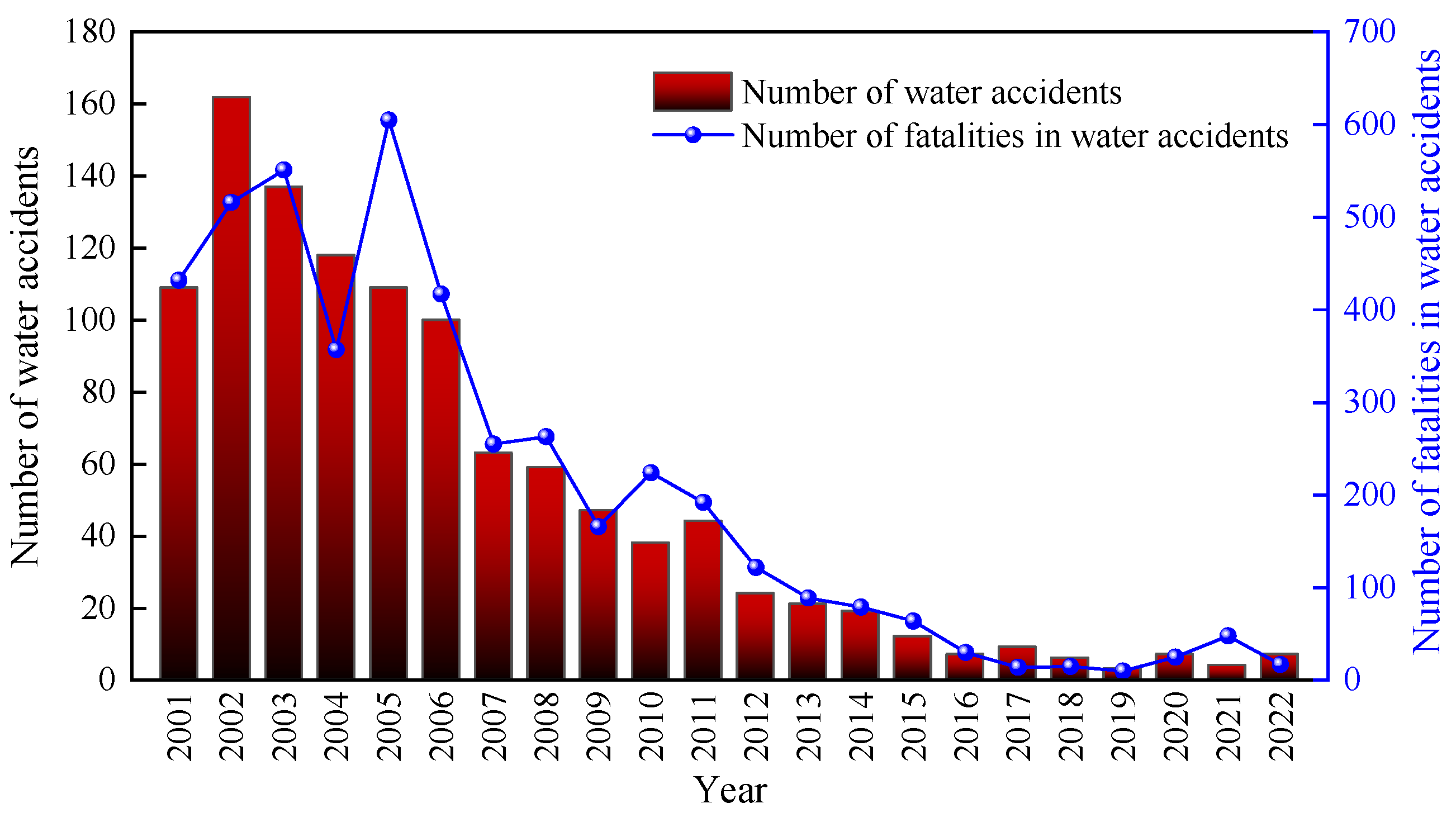
According to the statistical data on coal mine water-related accidents in China from 2001 to 2022, as shown in Figure 1, a total of 1105 water inrush accidents occurred nationwide during this period, resulting in 4491 fatalities. Both the number of accidents and the associated death toll remained at relatively high levels between 2001 and 2006, with 2002 being particularly severe, when 162 accidents occurred, and 516 fatalities were reported. Thereafter, both indicators exhibited an overall downward trend. Since 2016, the number of coal mine water-related accidents in China has decreased significantly, with annual fatalities being controlled below 50 and showing a steady declining trend. Nevertheless, with the acceleration of coal resource exploitation and the increasing complexity of geological conditions, the frequency of water-related accidents and the number of fatalities have shown a slight rebound in recent years. This indicates that the prevention and control of mine water hazards remain highly challenging and require sustained and intensified attention [24,25,26,27,28,29].
To address water-related hazards in coal mining, extensive research has been conducted on water inrush mechanisms, risk assessment, and engineering control measures, forming a comprehensive prevention and control framework that integrates theoretical analysis with practical applications. Dong et al. [31] investigated the evolution of floor failure depth and the mechanism of water inrush under conditions of high confined pressure in Ordovician limestone aquifers, focusing on strong mining-induced stress disturbances associated with ultra-wide working faces. They proposed an active regulation method based on roof cutting and pressure relief to modify the overburden structure, thereby reducing floor damage and effectively controlling both the depth of floor failure and the risk of water inrush. Wang et al. [32] developed a floor water inrush risk assessment model using a coupled triangular fuzzy number and set pair analysis approach, and further proposed a comprehensive floor water hazard control strategy that combines grouting reinforcement of aquicludes with borehole drilling and transient electromagnetic methods for dynamic effectiveness verification. Dong et al. [33], taking ultra-wide working face mining near faults under deep, high-confined-pressure aquifer conditions in the North China coalfield as the research background, examined the mechanisms of floor failure and the formation of water-conducting fracture channels under the coupled effects of mining-induced stress and confined water pressure. Based on this, a novel method for determining the width of waterproof coal–rock pillars was proposed, effectively mitigating the risk of fault-related water inrush. Hao et al. [34] evaluated the emergency response capacity for water-related accidents in five typical coal mines by integrating the analytic hierarchy process with fuzzy comprehensive evaluation, thereby establishing an emergency system assessment model that systematically enhances the overall effectiveness of water hazard emergency response systems.
In addition, Wang et al. [35] combined the sparrow search algorithm with a convolutional neural network to develop an intelligent prediction model for roof water inflow, enabling accurate early warning and proactive prevention of roof water hazards when integrated with advanced detection techniques such as radio-wave tomography. Long et al. [36] achieved early identification of the development range of mining-induced fracture zones and precise localization of potential water inrush channels by integrating microseismic absorption coefficient imaging with dynamic monitoring techniques. Xie et al. [37] indicated that the risk of water inrush beneath separated water bodies is primarily controlled by the integrity of key aquicludes and the degree of separation space developed. Accordingly, they proposed implementing separation-zone grouting and filling in high-risk areas, based on a combination of drilling and geophysical exploration, to effectively block potential hydraulic pathways. Shi et al. [38] investigated the evolution of overburden water-conducting fracture zones and the formation and inrush mechanisms of separation water, demonstrating that the fracture of ultra-thick sandstone key strata is the primary trigger for the sudden inflow of separation water. On this basis, they proposed the construction of grouting boreholes as an active measure for water hazard control. Liu et al. [39] suggested that microseismic energy parameters should be regarded as key indicators for premonitory warning of water inrush. Xing et al. [40], in the context of preventing floor water inrush through gangue backfill mining, revealed through laboratory experiments the influence mechanisms of gangue gradation and stress state on seepage characteristics. A permeability evolution model was subsequently established, demonstrating that optimizing gradation can significantly reduce the permeability of the backfill body and enhance its water-blocking capacity, thereby effectively cutting off confined water uplift pathways.
Existing studies have yielded substantial achievements in the prevention and control of water hazards under single-seam mining or specific geological conditions. However, under coal seam group mining conditions—particularly when water accumulation in upper-seam gobs threatens repeated mining in lower seams—the interlayer strata are subjected to multiple mining disturbances. Consequently, the mechanisms of cumulative damage, fracture connectivity evolution, and water hazard prevention become considerably more complex. Therefore, further in-depth research and engineering validation are still required to determine how to actively intervene in overburden fracture processes and regulate the development paths of water-conducting channels to achieve effective water hazard control.
Against this background, this study takes the 31110 panel of the Huoluowan Coal Mine as the engineering case. Focusing on the water inrush risk posed by accumulated water in the gob of the overlying 2−2 coal seam to the mining of the underlying 3−1 coal seam, a comprehensive approach combining theoretical analysis, numerical simulation, and field experiment is employed. The cumulative damage and fracture connectivity mechanisms of interlayer strata under coal seam group mining conditions are investigated, and the regulatory effects of roof cutting and pressure-relief measures on interlayer rock damage are analyzed. Furthermore, the active blocking mechanism of water-conducting channel development paths is elucidated, and the effectiveness of the proposed technology is verified through on-site hydraulic fracturing engineering. The results are expected to provide a theoretical basis and technical reference for the prevention and control of water inrush under similar geological and mining conditions.

2. Research Object and Method

2.1. Research Object

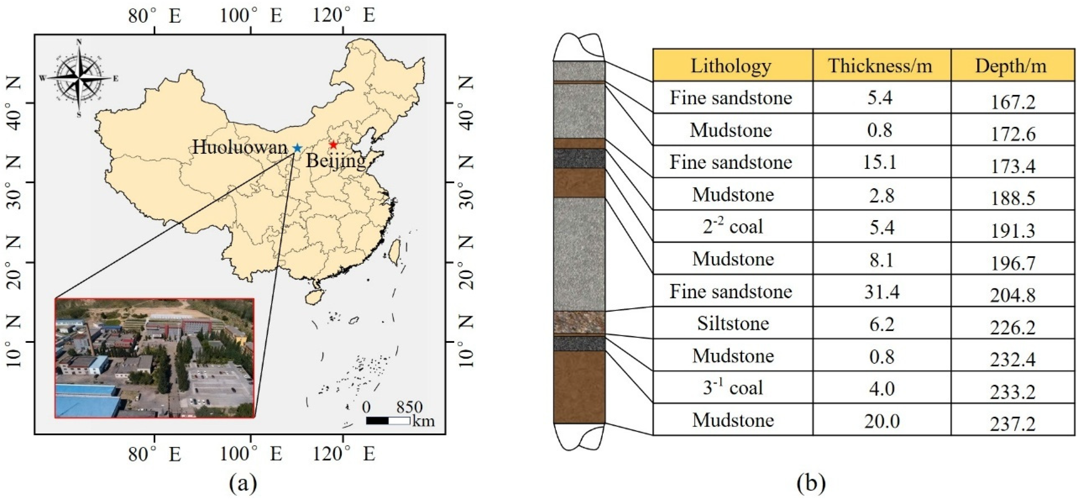
Huoluowan Coal Mine is located in Ordos City, China, and is operated by Shendong Tianlong Group Co., Ltd. The mine lease area covers approximately 13.2 km2, and its geographical location is shown in Figure 2a. The mine primarily exploits the 2−2 and 3−1 coal seams, which are separated by an interburden thickness of 46.5 m. The 2−2 coal seam has an average thickness of 5.4 m and an average burial depth of 191.3 m. Its immediate roof lithology is mainly composed of mudstone and fine-grained sandstone. Multiple mining methods, including blasting mining and fully mechanized longwall mining, have been employed in this seam, resulting in the formation of various types of residual coal pillars, such as protective coal pillars for gateroads, centralized main roadway coal pillars, and room-and-pillar remnants. The 3−1 coal seam is the current main mining seam, with an average thickness of 4.0 m and an average burial depth of 233.2 m. Its roof strata are also dominated by mudstone and fine-grained sandstone. The 3−1 coal seam exhibits stable occurrence conditions, a simple geological structure, and a dip angle of 1–3°, classifying it as a near-horizontal coal seam. The stratigraphic column of the coal-bearing strata is illustrated in Figure 2b.
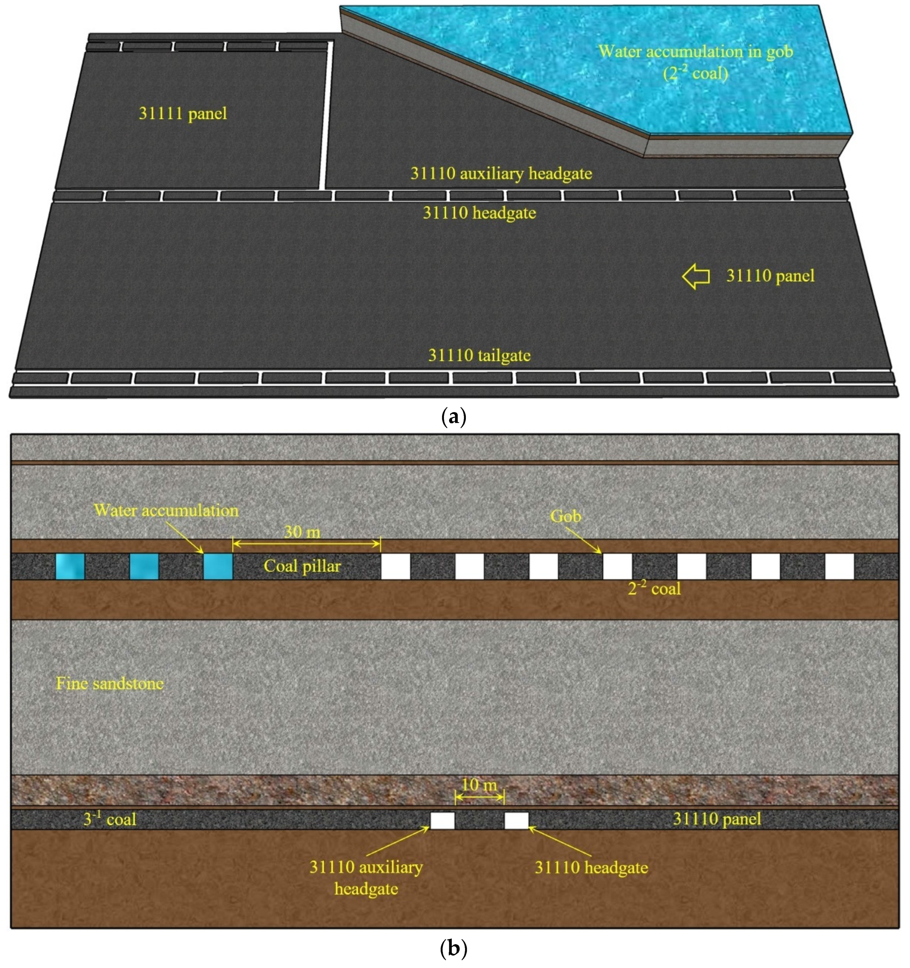
The 31110 panel is situated in the southeastern part of the mine. It has an inclined length of 240 m and a strike length of approximately 3500 m, and it is adjacent to the 31111 panel. The inclined longwall retreating fully mechanized mining method is adopted at this working face. A total of three roadways are used, namely, the 31110 tailgate, 31110 headgate, and 31110 auxiliary headgate. After the completion of mining at the 31110 panel, the 31110 auxiliary headgate is retained and reused as the tailgate for the adjacent 31111 panel. Notably, accumulated water exists in the gob of the overlying 2−2 coal seam above the 31110 auxiliary headgate.
The layout of the 31110 panel is shown in Figure 3. Both the 31110 headgate and 31110 auxiliary headgate are excavated along the floor of the 3−1 coal seam, with a 10 m wide protective coal pillar left between adjacent roadways. A water-filled gob in the 2−2 coal seam is located above the 31110 auxiliary headgate, and a 30 m wide coal pillar is left between the water-filled and non-water-filled gob areas.
Between the upper 2−2 coal seam and the lower 3−1 coal seam lies a 31.4 m thick fine-grained sandstone layer. Under intact conditions, this layer serves as a critical aquiclude. However, once its integrity is compromised by mining-induced disturbances, it may transform into a water-conducting medium. As the 31110 working face advances, if the overlying fine-grained sandstone fractures above the solid coal side of the 31110 auxiliary headgate under mining-induced stress, fractures may propagate upward and connect with the overlying 2−2 coal seam gob. Consequently, accumulated water in the gob may rush into the 31110 auxiliary headgate of the lower 3−1 coal seam through connected fractures and rock mass seepage, thereby triggering a water inrush accident.
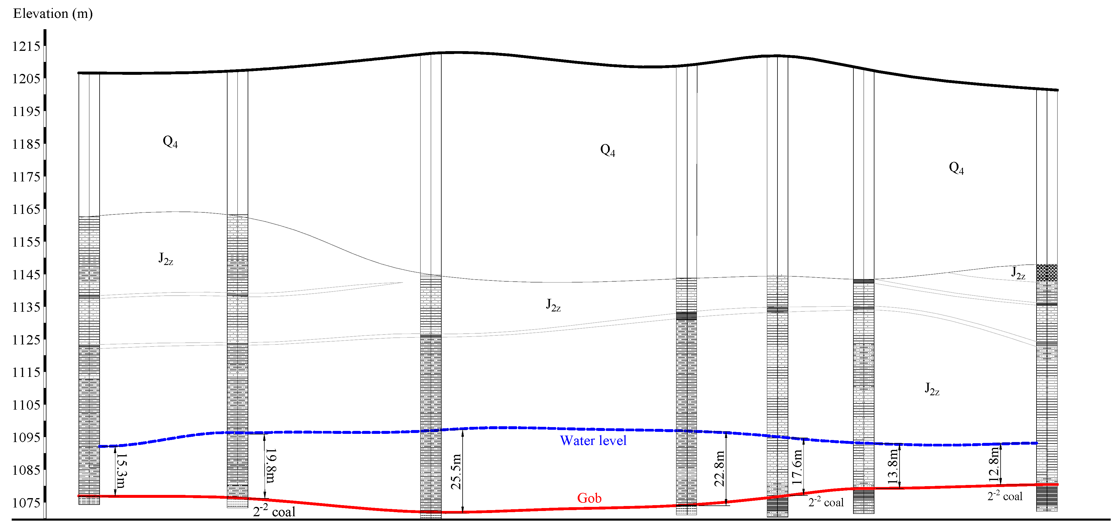
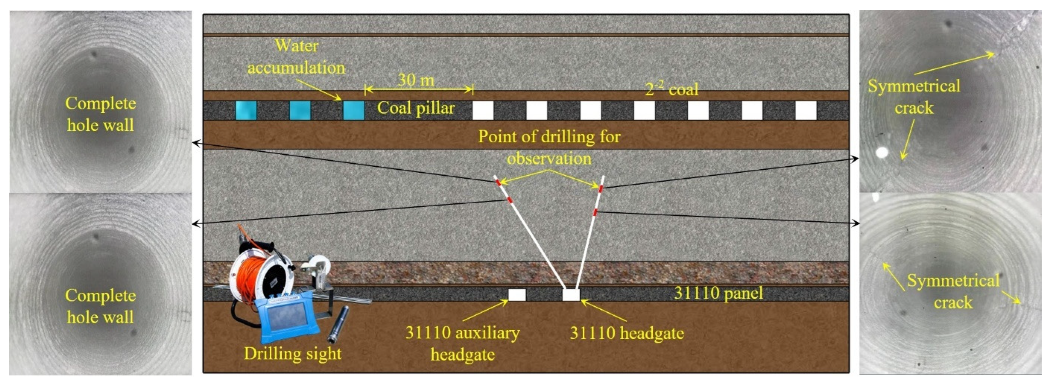
To investigate the water accumulation conditions in the gob of the overlying 2−2 coal seam, seven vertical exploration boreholes were drilled on site. The drilling results are presented in Figure 4.
The drilling data indicate that well-developed vertical fractures and a fractured zone are present in the roof of the 2−2 coal seam gob. The roof strata are predominantly characterized by fragmentation, and a high degree of fracture development is observed within the coal pillars. All boreholes revealed the presence of water in the gob, with static water levels ranging from +1107.9 m to +1120.5 m. Based on the drilling data, the accumulated water volume in the gob is preliminarily estimated to be approximately 5.0 × 10⁵ m3, with an associated water pressure of about 0.2 MPa.

2.2. Research Method

A comprehensive methodology integrating theoretical analysis, numerical simulation, and engineering validation was employed to systematically investigate the mechanism of gob water inrush under repeated mining.
(1)
Theoretical Analysis: Theoretical mechanics models and empirical formulas were utilized to analyze the potential for hydraulic connectivity between the upper water-filled gob and the lower mining operations.
(2)
Numerical Simulation: A three-dimensional numerical model was established using the FLAC3D finite difference code to simulate the coupled stress-seepage behavior of the rock mass under repeated mining disturbances.
(3)
Engineering Validation: Based on the theoretical and numerical findings, a specific hydraulic fracturing scheme for roof cutting and pressure relief was designed and implemented at the 31110 panel. Field trials were conducted to verify the practical feasibility and effectiveness of the proposed control technology.

3. Results of Theoretical Analysis

3.1. Analysis of Floor-Seepage Depth Induced by Upper Coal Seam Mining

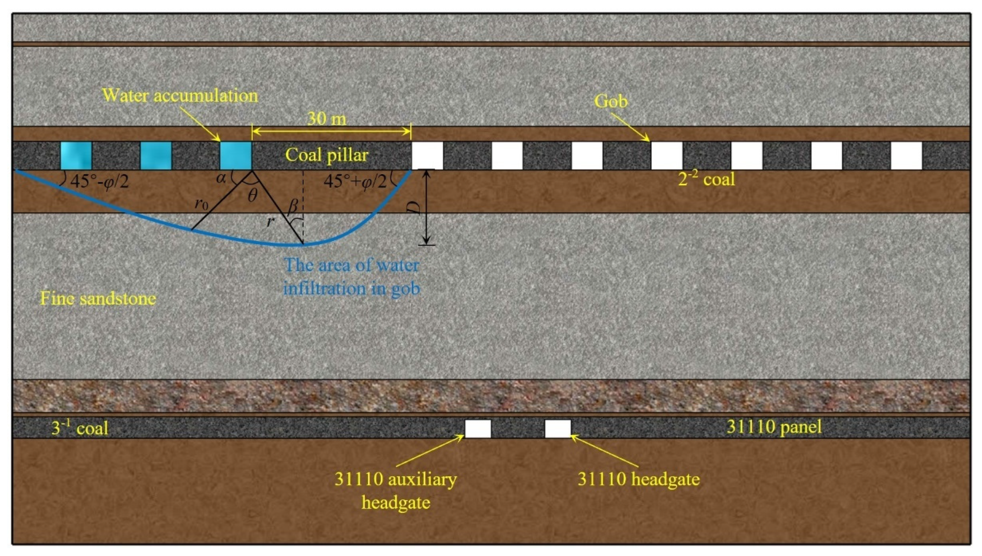
After the extraction of the overlying 2−2 coal seam, the underlying floor strata undergo deformation and develop damage-induced fractures under the disturbance of mining-induced stresses. These fractures provide potential pathways for the downward seepage of accumulated water in the gob. Based on slip-line field theory in plastic mechanics, the depth of floor failure can be determined, which corresponds to the downward seepage depth of gob water from the upper coal seam, denoted as D . During the mining process, the floor-seepage depth formed under the influence of abutment pressure is illustrated in Figure 5.
In the slip-line field mechanical model [41], the parameter φ represents the internal friction angle of the floor rock mass. The two straight boundaries of the slip-line field form angles of 45 ° φ / 2 and 45 ° φ / 2 , respectively, with the direction of the maximum principal stress. The curved portions consist of a set of logarithmic spirals, which represent the slip trajectories of rock mass particles within the plastic zone of the floor. Here, r 0 denotes the initial polar radius from the coal wall edge to the apex of the plastic zone, while r and θ represent the polar radius and polar angle of any point along the slip line, respectively. The parameters α and β are angular variables that characterize the geometric configuration of the slip-line field and jointly define the extent of the plastic failure zone in the floor strata. The α -family and β -family slip lines together form the complete slip-line network, delineating the plastic failure range of the floor rock mass under ultimate loading conditions.
The polar coordinate equation of the logarithmic spiral slip line is expressed as follows [41]:
D = r cos θ = r 0 e α tan φ cos θ
r 0 = L 2 cos ( π 4 + φ 2 )
θ = α + φ 2 π 4
where L is the length of the coal body yield zone, given by the following:
L = m 1 sin φ 0 2 1 + sin φ 0 tan φ 0 ln n γ H + C cot φ 0 1 sin φ 0 1 + sin φ 0 C cot φ 0
By setting d D / d α = 0 , the maximum floor-seepage depth can be obtained as follows:
d D d α = r 0 e α tan φ cos α + φ 2 π 4 tan φ r 0 e α tan φ sin α + φ 2 π 4 = 0
According to the Mohr–Coulomb failure criterion,
β = α π 4 + φ 2
Similarly, the critical condition yields the following:
α = π 4 + φ 2
Substituting r 0 into Equation (1), the maximum floor-seepage depth D m a x can be expressed as follows:
D m a x = m 1 sin φ 0 sin φ 4 1 + sin φ 0 tan φ 0 cos ( π 4 + φ 2 ) e ( π 4 + φ 2 ) tan φ ln n γ H + C cot φ 0 1 sin φ 0 1 + sin φ 0 C cot φ 0
where m is the mining thickness of the coal seam (m); γ is the average unit weight of the rock mass; H is the burial depth of the coal seam (m); C is the cohesion of the coal seam (MPa); φ is the internal friction angle of the floor rock mass (°); φ 0 is the internal friction angle of the coal seam (°); and n is the maximum stress concentration factor.
Based on the geological conditions of the 31110 panel, the following parameters are adopted: H = 191 m, m = 5.4 m, γ = 25 kN/m3, φ = 30 ° , φ 0 = 25 ° , n = 3 , C = 1.0 MPa. Substituting these values into Equation (8) yields a maximum floor-seepage depth of D m a x = 2.43 m.

3.2. Analysis of the Height of the Water-Conducting Fracture Zone in the Roof Induced by Lower Coal Seam Mining

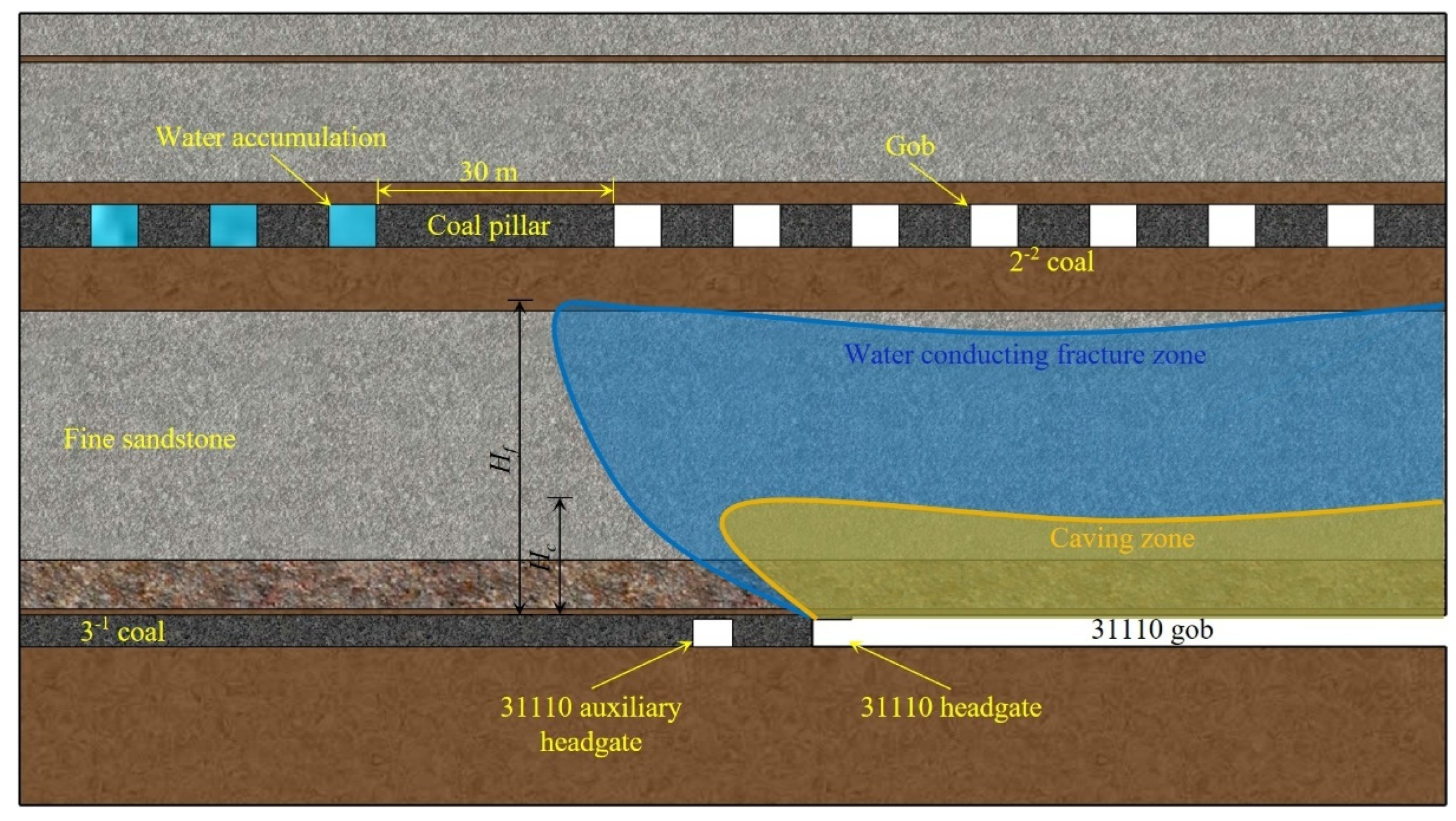
The damage range of the roof strata induced by mining of the lower coal seam can be evaluated using the three-zone theory [42]. According to this theory, the overburden above the gob is divided into the caving zone, the water-conducting fracture zone, and the bending subsidence zone. As shown in Figure 6, the yellow region represents the caving zone, while the blue region denotes the water-conducting fracture zone. The caving zone and the water-conducting fracture zone may connect with the floor damage zone formed by the mining of the upper coal seam, thereby inducing secondary damage to residual coal pillars in the upper seam, as well as secondary roof failure and sliding instability.
At present, the heights of the caving zone and the water-conducting fracture zone are primarily determined through field measurements and theoretical calculations. From a theoretical perspective, the height of the caving zone can be calculated using the following equation:
H c = M K p 1 cos α
where M is the mining thickness of the coal seam (m); K p is the bulking coefficient of caved rock, generally obtained from field measurements and typically ranging from 1.2 to 1.4; and α is the dip angle of the coal seam (°).
Based on the in situ geological conditions, the mining thickness is taken as 4.0 m and the coal seam dip angle as 2°. Substituting these values into Equation (9) yields a caving zone height in the range of 10.01–20.01 m.
The height of the water-conducting fracture zone can be estimated using the empirical formulas summarized in Table 1.
At the 31110 panel of Huoluowan Coal Mine, fully mechanized longwall mining is employed, and the roof strata are dominated by thick, hard fine-grained sandstone. Therefore, the empirical formula corresponding to hard rock lithology in Table 1 is adopted to calculate the height of the water-conducting fracture zone, with the mining thickness taken as 4.0 m. The calculated height of the water-conducting fracture zone ranges from 49.92 to 67.72 m.

3.3. Engineering Challenges Under In Situ Conditions

Based on the above calculations, the maximum floor-seepage depth induced by mining of the 2−2 coal seam is 2.43 m; the height of the caving zone caused by mining of the 3−1 coal seam ranges from 10.01 to 20.01 m; and the height of the water-conducting fracture zone ranges from 49.92 to 67.72 m. Superimposing these damage ranges yields a cumulative interlayer failure depth between the upper and lower coal seams of 62.36–90.16 m. However, the actual vertical separation between the 2−2 and 3−1 coal seams is only 46.5 m, which is significantly smaller than the calculated damage range. This condition satisfies the connectivity criterion expressed in Equation (10), indicating that damage has propagated through the interlayer strata and formed a continuous failure zone.
H < D m a x + H c + H f
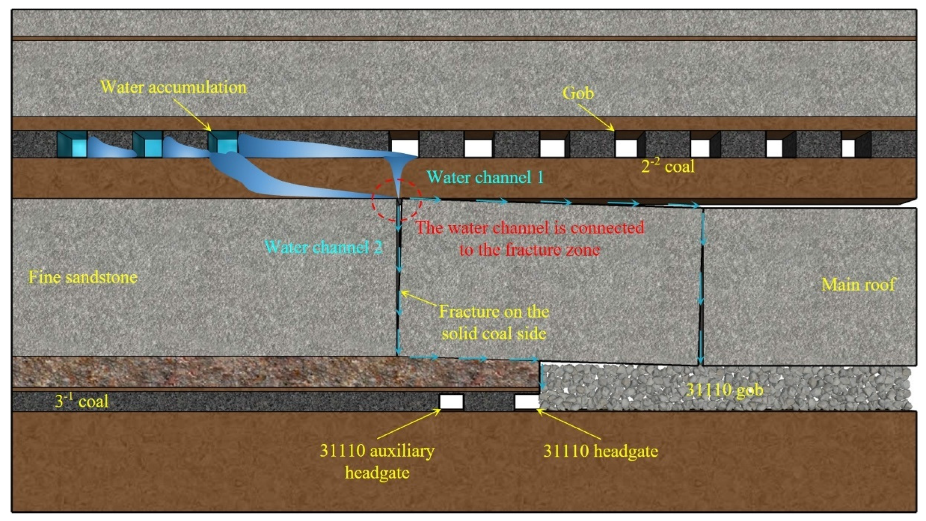
As illustrated in Figure 7, with the advancement of the 31110 panel, the main roof of the 3−1 coal seam fractured on the solid coal side above the 31110 auxiliary headgate under the influence of mining-induced stress disturbances, thereby forming a continuous water-conducting pathway between the upper and lower coal seams. Under such conditions, accumulated water in the gob of the 2−2 coal seam may rush into the roadways of the lower 3−1 coal seam along the water-conducting channel, posing a pronounced risk of water inrush.
Field measurements further confirm the severity of the water inrush hazard. After mining of the 31110 panel, the maximum development height of the water-conducting fracture zone in the overburden reached 66 m, corresponding to a fracture–mining ratio of 16.5. The height of the caving zone was approximately 18 m, with a caving–mining ratio of 4.5. The mining-induced fracture system continued to propagate upward and has already connected with the gob of the overlying 2−2 coal seam, thereby forming a potential water inrush channel linking the water-filled gob to the lower roadway system.
The above theoretical analysis and field observations indicate that, under mining-induced stress conditions, if the main roof fractures on the solid coal side above the 31110 auxiliary headgate, a water-conducting channel will directly connect above the roadway. This leads to the loss of integrity of the overburden strata and prevents the formation of an effective aquiclude. To mitigate such water inrush risks, proactive intervention measures, such as roof cutting and pressure relief by hydraulic fracturing [44], can be implemented. By artificially controlling the fracture location of the main roof [45,46,47] and inducing roof breakage toward the gob side of the lower coal seam, the integrity of the strata above the roadway can be preserved. This facilitates the formation of a key aquiclude, thereby effectively blocking the development and interconnection of water-conducting pathways.

4. Results of Numerical Simulation

4.1. Model Establishment

To elucidate the formation mechanism of water-conducting channels under mining-induced disturbances and to evaluate the effectiveness of roof cutting measures in water hazard control, a numerical model was established using FLAC3D based on the actual geological conditions of the 31110 panel at Huoluowan Coal Mine. The evolution characteristics of the overburden plastic zone, stress field, and displacement field under different roof cutting schemes were systematically investigated, providing a basis for the optimization design of roof cutting measures.
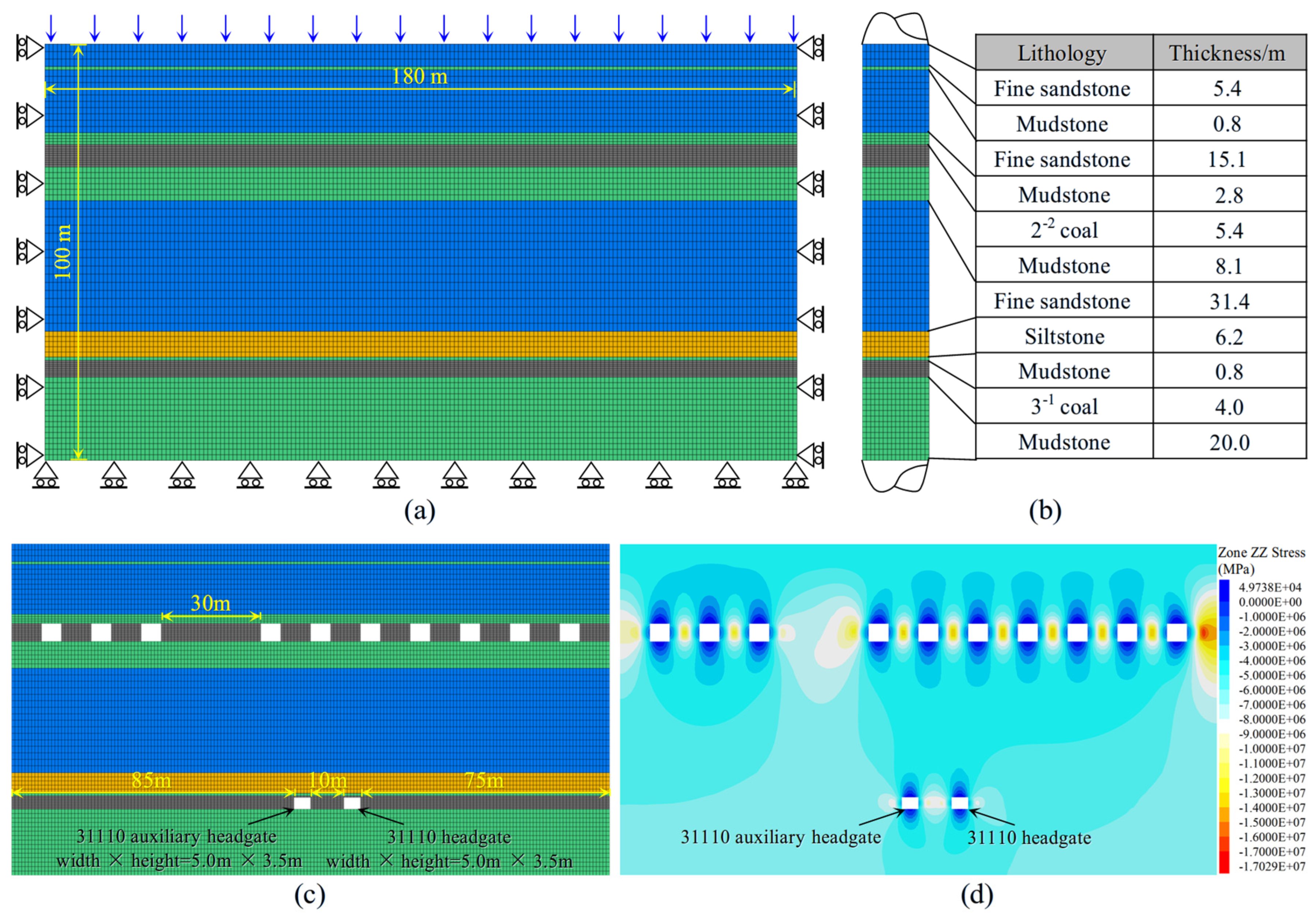
According to the stratigraphic column shown in Figure 2 and in situ geological data, the numerical model was constructed as illustrated in Figure 8. From top to bottom along the vertical direction, the model includes the 2−2 coal seam and its immediate roof and floor, the interlayer strata, and the 3−1 coal seam with its roof and floor. The overall model dimensions are 180 m (length) × 1 m (width) × 100 m (height), where the width direction is consistent with the strike direction of the working face. Refer to the mesh size division in references [48,49,50] to determine the mesh size of the model. At the same time, in order to ensure the accuracy of the research area, the grid size of 3−1 coal is further densified. Displacement constraints were applied to the lateral boundaries and the bottom of the model, while a uniformly distributed load equivalent to the self-weight of the overlying strata was applied to the top boundary [51,52]. The Mohr–Coulomb yield criterion was adopted as the constitutive model for the rock mass. According to the mechanical parameters provided by the Huoluowan Coal Mine, the mechanical parameters of the model are determined as shown in Table 2.
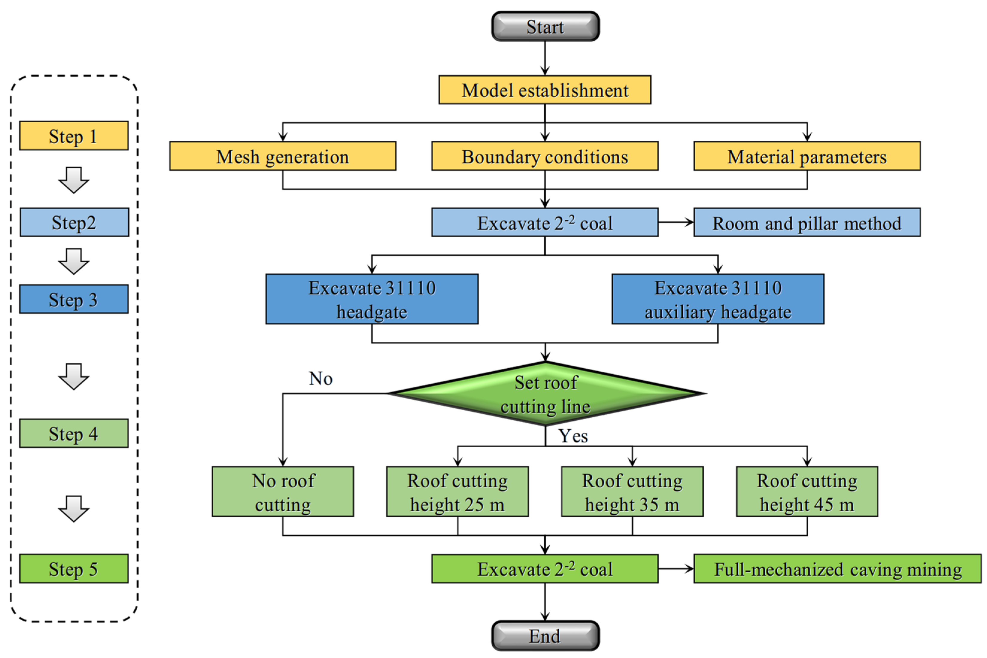
The numerical simulation was conducted in accordance with the actual mining sequence in the field. The specific simulation procedure is shown in Figure 9, and the main steps are as follows:
(1)
Model initialization.
After completing mesh generation, boundary conditions were applied, and the mechanical parameters of each stratum were assigned according to Table 2. Initial in situ stresses and boundary loads were then imposed, and the model was calculated to an initial equilibrium state to simulate the original stress conditions of the strata.
(2)
Mining of the 2−2 coal seam.
To replicate the field mining conditions, the 2−2 coal seam was excavated using a room-and-pillar method, with a mining width of 6 m and coal pillars of 9 m left in place, thereby simulating the geometry of the residual gob.
(3)
Excavation of roadways in the 3−1 coal seam.
The 31110 headgate and the 31110 auxiliary headgate were excavated sequentially to simulate the redistribution of surrounding rock stress after roadway formation.
(4)
Roof cutting scenarios.
In this study, we drew on the approach presented in reference [53]. Specifically, we defined the roof cutting line in the model by introducing a vertical interface at the roof cutting location. This interface effectively serves as a substitute for the roof cutting line, severing the connection between the elements on the left and right sides of the model. By doing so, we were able to simulate the separation that occurs during the roof cutting process. Regarding the contact simulation between the left and right parts of the model from the roof cutting line, the vertical interface we set up inherently handles this aspect by preventing the transfer of forces and displacements across it, which accurately represents the physical situation after roof cutting. Four simulation scenarios were designed: (i) no-roof cutting; (ii) roof cutting height of 25 m; (iii) roof cutting height of 35 m; and (iv) roof cutting height of 45 m. In the roof cutting scenarios, a predefined cutting line was arranged in the roof above the 31110 headgate. A contact interface was introduced in the model to simulate the weak-plane effect induced by directional hydraulic fracturing, thereby artificially guiding the roof to preferentially fracture toward the gob side.
(5)
Mining of the 31110 panel
Fully mechanized top-coal caving mining was adopted to simulate the extraction of the 31110 working face, and the gob was treated using the caving method.

4.2. Distribution Characteristics of the Plastic Zone

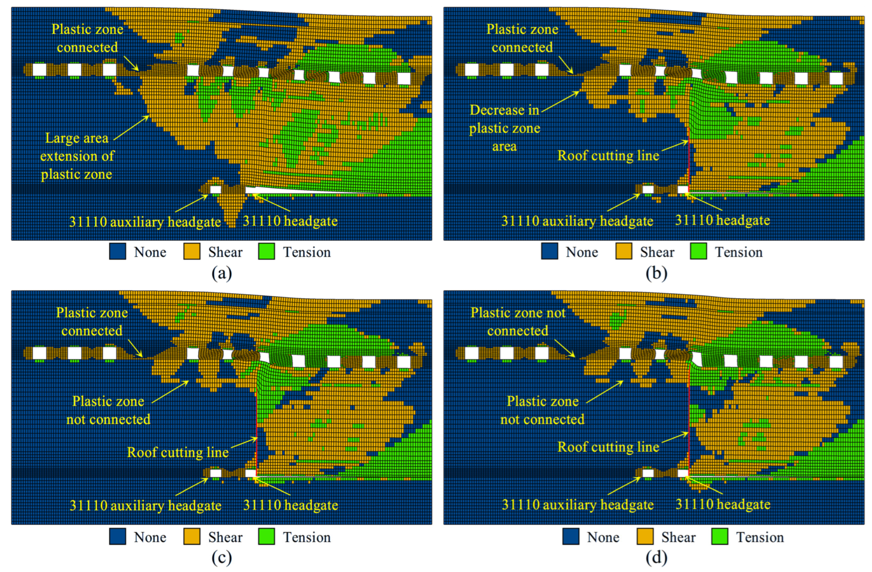
The distribution characteristics of the plastic zone in the overlying strata above the 31110 panel under conditions without roof cutting and with different roof cutting heights are shown in Figure 10.
As illustrated in Figure 10a, under the no roof cutting condition, the plastic zone in the overlying strata exhibits the widest development range and the strongest connectivity. Room-and-pillar mining of the upper 2−2 coal seam caused floor damage, and with the advance of the lower 31110 panel, the caving zone and the water-conducting fracture zone in the roof became fully developed. The plastic failure zone propagated upward and became completely connected with the plastic damage zone of the residual gob in the 2−2 coal seam. Meanwhile, through-going plastic failure also occurred within the 30 m wide isolation coal pillar separating the water-filled and non-water-filled areas of the 2−2 coal seam. In particular, above the solid coal side of the 31110 auxiliary headgate, a large-scale shear plastic zone developed within the main roof, which originally acted as a key aquiclude. This shear zone connected downward with mining-induced fractures and upward with the floor damage zone of the 2−2 coal seam, indicating that under natural roof-breaking conditions, mining-induced fractures had completely penetrated the interlayer strata, forming a continuous water-conducting pathway. Under such circumstances, gob water can migrate through the aquiclude coal pillar and interlayer-connected fractures into the 31110 auxiliary headgate, resulting in an extremely high risk of water inrush.
As shown in Figure 10b, when the roof cutting height is 25 m, the pre-established weak plane guides the main roof to fracture in advance toward the gob side, effectively shortening the roof cantilever length and alleviating stress concentration on the solid coal side. Consequently, plastic damage is partially controlled. Compared with the no roof cutting case, both the development range and connectivity of the plastic zone in the interlayer strata are significantly reduced, and the fracture connectivity within the aquiclude coal pillar of the 2−2 coal seam is also markedly weakened. However, due to the limited roof cutting height, the connectivity between the plastic failure zone in the aquiclude coal pillar and that in the interlayer strata is not completely interrupted, and the potential for forming a through-going water-conducting channel still exists. Therefore, although the water inrush risk is initially mitigated under this condition, it is not fundamentally eliminated, and further improvement in control effectiveness is required.
As depicted in Figure 10c, when the roof cutting height is increased to 35 m, the distribution pattern and connectivity of the overburden plastic zone are substantially improved. Under this condition, the main roof fractures sufficiently on the gob side, and the key aquiclude remains relatively intact. Compared with the 25 m roof cutting scenario, a cutting height of 35 m further suppresses the vertical extension of the plastic zone within the interlayer strata. Although local through-going fractures still exist within the aquiclude coal pillar of the 2−2 coal seam, no continuous plastic connectivity is formed between these fractures and the mining-induced damage zone of the lower 3−1 coal seam. In particular, the shear plastic zones in the interlayer strata on the solid coal side exhibit a discontinuous distribution, indicating that the water-conducting pathways between the upper and lower coal seams have been partially blocked. This distribution characteristic suggests that, although a 35 m roof cutting height cannot completely eliminate internal fractures within the aquiclude coal pillar itself, guiding the main roof to fracture toward the gob side effectively disconnects the fractures in the aquiclude coal pillar from the damage zone in the lower strata, while ensuring the integrity of the key interlayer aquiclude.
As shown in Figure 10d, when the roof cutting height is further increased to 45 m, the distribution pattern of the overburden plastic zone is further optimized. Under this condition, damage to the interlayer strata on the solid coal side is more effectively controlled, and the plastic zone within the aquiclude coal pillar of the 2−2 coal seam completely loses its connectivity. The plastic connection paths between the aquiclude coal pillar and the mining-induced damage zone of the lower 3−1 coal seam are entirely isolated. This indicates that the potential water-conducting channels between the upper and lower coal seams have been completely blocked, and the integrity of the key interlayer aquiclude is effectively maintained, thereby eliminating the risk of water inrush.
In summary, the roof cutting and pressure-relief technique, through the pre-establishment of an artificial weak plane, can effectively regulate the fracture position of the main roof and thereby significantly alter the development pattern and connectivity characteristics of the overburden plastic zone. Under no roof cutting conditions, the main roof fractures on the solid coal side, leading to full connectivity of the plastic zone and through-going damage of the interlayer strata, which forms a water-conducting pathway and results in an extremely high-water inrush risk. With increasing roof cutting height, the main roof preferentially fractures toward the gob side, stress concentration on the solid coal side is significantly alleviated, and the extent and connectivity of the plastic zone are progressively reduced. When the roof cutting height reaches 35 m or greater, the plastic connectivity between the aquiclude coal pillar and the mining-induced damage zone of the lower seam is interrupted, the key interlayer strata remain intact, and water-conducting channels are effectively blocked, resulting in a pronounced improvement in water inrush control performance.

4.3. Vertical Stress Distribution

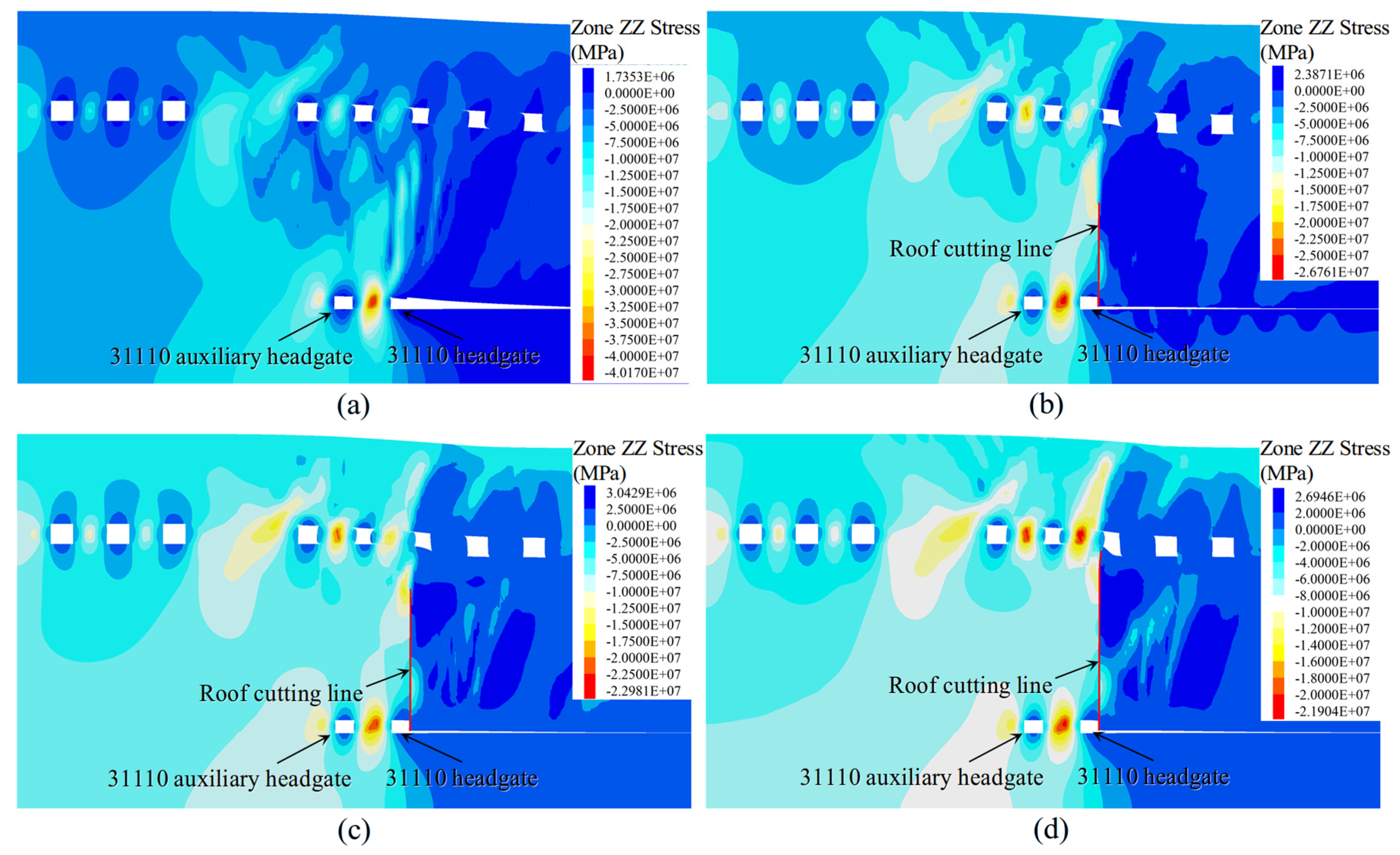
The vertical stress distribution characteristics of the overlying strata above the 31110 panel under conditions without roof cutting and with different roof cutting heights are shown in Figure 11.
As shown in Figure 11a, under the no roof cutting condition, the coal pillar between the 31110 headgate and the 31110 auxiliary headgate is subjected to highly concentrated abutment pressure, with a peak stress of 40.17 MPa. This high-stress zone propagates upward into the overlying strata, resulting in a significant increase in stress at the floor of the upper 2−2 coal seam. Together with the aquiclude coal pillar, it forms a continuous high-stress concentration belt. Under the sustained action of high stress, extensive shear-dominated plastic failure develops within the interlayer strata, inducing fracture of the main roof on the solid coal side of the 31110 auxiliary headgate. The through-going damage of the rock mass compromises the integrity of the key aquiclude, ultimately forming a connected water-conducting pathway between the upper and lower coal seams and leading to an extremely high risk of water inrush.
As illustrated in Figure 11b, when the roof cutting height is 25 m, the stress distribution is preliminarily regulated. By introducing a pre-designed weak plane to guide the main roof to fracture toward the gob side, stress concentration within the coal pillar between the auxiliary transportation roadway and the transportation roadway is significantly reduced. The peak stress decreases to 26.76 MPa, and the extent of the high-stress influence zone is markedly diminished. The alleviation of stress concentration mitigates rock mass damage on the solid coal side, resulting in a notable reduction in both the extent and connectivity of the plastic zone. However, owing to the limited roof cutting height, the coal pillar and the overlying key strata remain under relatively high stress, and the plastic damage zones within the aquiclude coal pillar and the interlayer strata are not fully isolated. As a result, localized water-conducting pathways may still exist, and the risk of water inrush is not completely eliminated.
As shown in Figure 11c, when the roof cutting height is increased to 35 m, the stress distribution is further optimized, and the control effectiveness is significantly enhanced. The pre-established roof cutting weak plane ensures sufficient fracture of the main roof on the gob side, leading to a pronounced reduction in stress concentration on the solid coal side. The peak stress within the coal pillar decreases to 22.98 MPa, and the high-stress zones become dispersed. Consequently, the key interlayer strata are subjected to a more uniform stress environment. Shear failure of the rock mass on the solid coal side is effectively suppressed, and the plastic connectivity between the aquiclude coal pillar and the mining-induced damage zone of the lower seam is completely interrupted, thereby effectively controlling the risk of water inrush.
As shown in Figure 11d, when the roof cutting height is further increased to 45 m, the peak stress within the coal pillar is further reduced to 21.94 MPa. Both the solid coal side and the interlayer strata are generally subjected to a low and uniform stress state. The continuous improvement in the stress environment results in the complete isolation of plastic failure zones between the aquiclude coal pillar and the mining-induced damage zone of the lower seam, effectively preventing the formation of water-conducting channels and achieving a pronounced control effect on water inrush risk.
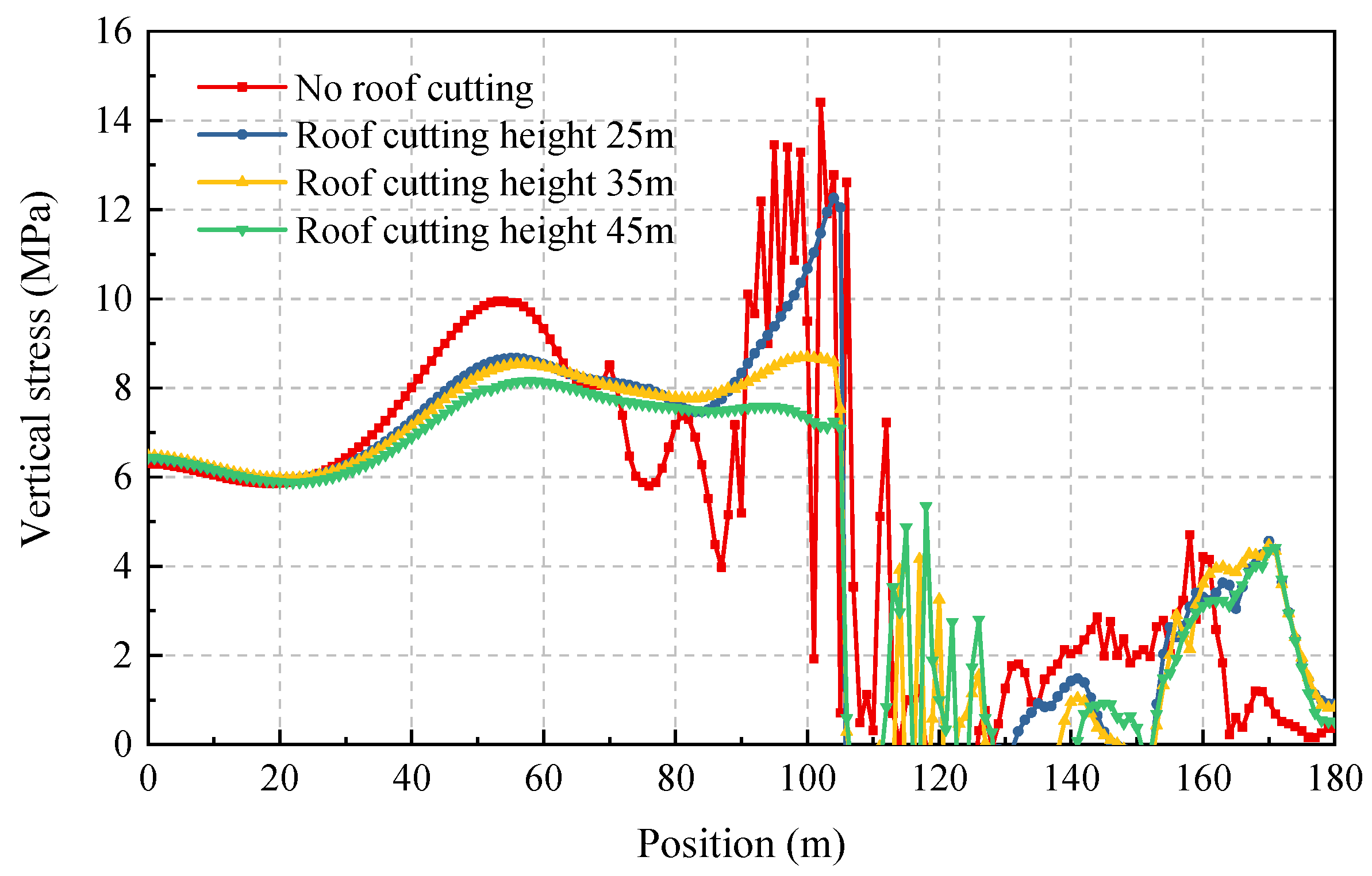
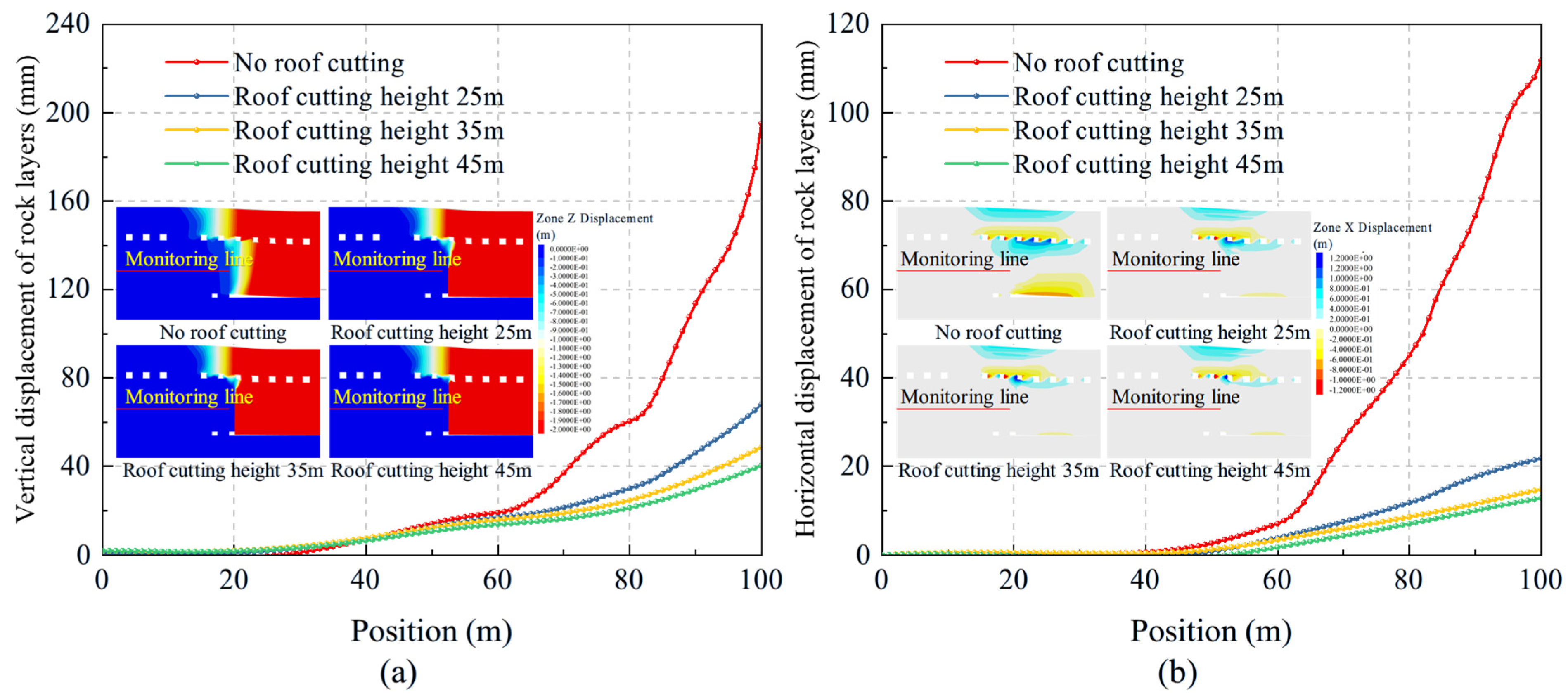
Given that the 31110 panel is located around 40 m beneath the 2−2 coal seam, a monitoring line measuring 180 m in length was placed at a horizon 20 m above the 31110 panel. This placement positions the monitoring line in the middle section between the upper and lower working faces, where the state of the rock strata is more representative for studying the vertical stress in the overlying strata. The monitoring results are presented in Figure 12.
Under the no roof cutting condition, a distinct stress peak occurs along the monitoring line within the 40–80 m interval, with a maximum value of approximately 10 MPa. In addition, pronounced stress fluctuations are observed near 100 m, where the peak stress exceeds 14 MPa. These results indicate the presence of significant stress concentration on the solid coal side and a highly non-uniform stress distribution, reflecting the combined effects of main roof fracture on the solid coal side and the sustained action of mining-induced stress, which leads to severe damage of the interlayer strata.
The implementation of roof cutting measures progressively optimizes stress distribution. When the roof cutting height is 25 m, the stress peak within the 40–80 m interval is reduced, and the fluctuation amplitude is initially alleviated; however, localized stress concentration remains near 100 m, with a peak stress of approximately 12 MPa. This indicates that only partial pressure relief is achieved under this condition, and residual stress concentration may still induce plastic zone connectivity. When the roof cutting height is increased to 35 m, the overall stress curve becomes smoother, with further reductions in peak stress and a significant decrease in fluctuation amplitude. This demonstrates that the main roof fractures sufficiently toward the gob side, effectively alleviating stress concentration on the solid coal side, which is beneficial for maintaining the integrity of the interlayer aquiclude and blocking water-conducting pathways. When the roof cutting height reaches 45 m, the stress curve is the smoothest, with the lowest peak stress and minimal fluctuations, indicating the most effective pressure-relief performance.

4.4. Deformation of the Overlying Strata

A monitoring line with a length of 100 m was arranged at a height of 20 m above the 31110 panel to record the vertical and horizontal displacements of the overlying strata. The objective was to evaluate the effectiveness of roof cutting measures in controlling the integrity of the interlayer rock mass on the solid coal side. The monitoring results are shown in Figure 13.
Under the no roof cutting condition, the overlying strata exhibit the most severe deformation, with maximum vertical and horizontal displacements reaching 195.2 mm and 111.9 mm, respectively. These results indicate that mining-induced disturbance causes pronounced subsidence and lateral deformation of the overlying strata, leading to severe degradation of interlayer rock mass integrity. Consequently, mining-induced fractures become fully connected, providing preferential water-conducting pathways for the downward migration of accumulated water from the gob.
With the implementation of roof cutting measures, strata deformation is effectively controlled. When the roof cutting height is 25 m, the maximum vertical displacement decreases to 68.2 mm, while the maximum horizontal displacement is reduced to 21.9 mm, representing a substantial reduction compared with the no roof cutting condition. This demonstrates that roof cutting, by guiding the main roof to fracture toward the gob side, preliminarily alleviates stress concentration on the solid coal side and suppresses damage development within the interlayer rock mass.
As the roof cutting height increases to 35 m, strata deformation further converges, with maximum vertical and horizontal displacements of 48.8 mm and 15.1 mm, respectively. These results indicate that the main roof fractures sufficiently on the gob side, effectively maintaining the integrity and continuity of the key aquiclude. When the roof cutting height reaches 45 m, the deformation control effect is optimal: the maximum vertical and horizontal displacements are reduced to only 40.5 mm and 12.8 mm, respectively, and the integrity of the interlayer rock mass is best preserved.
Comprehensive comparative analysis indicates that roof cutting measures, implemented through pre-established artificial weak planes, effectively guide the main roof to fracture toward the gob side. With increasing roof cutting height, the extent and connectivity of the plastic zone in the overlying strata are significantly reduced, the integrity of the key aquiclude is progressively enhanced, the stress distribution within the interlayer rock mass becomes more uniform, and strata deformation is markedly suppressed. As a result, the development and connectivity of water-conducting channels are effectively blocked, thereby achieving effective control of water inrush risk.

5. Engineering Verification

5.1. Hydraulic Fracturing Scheme

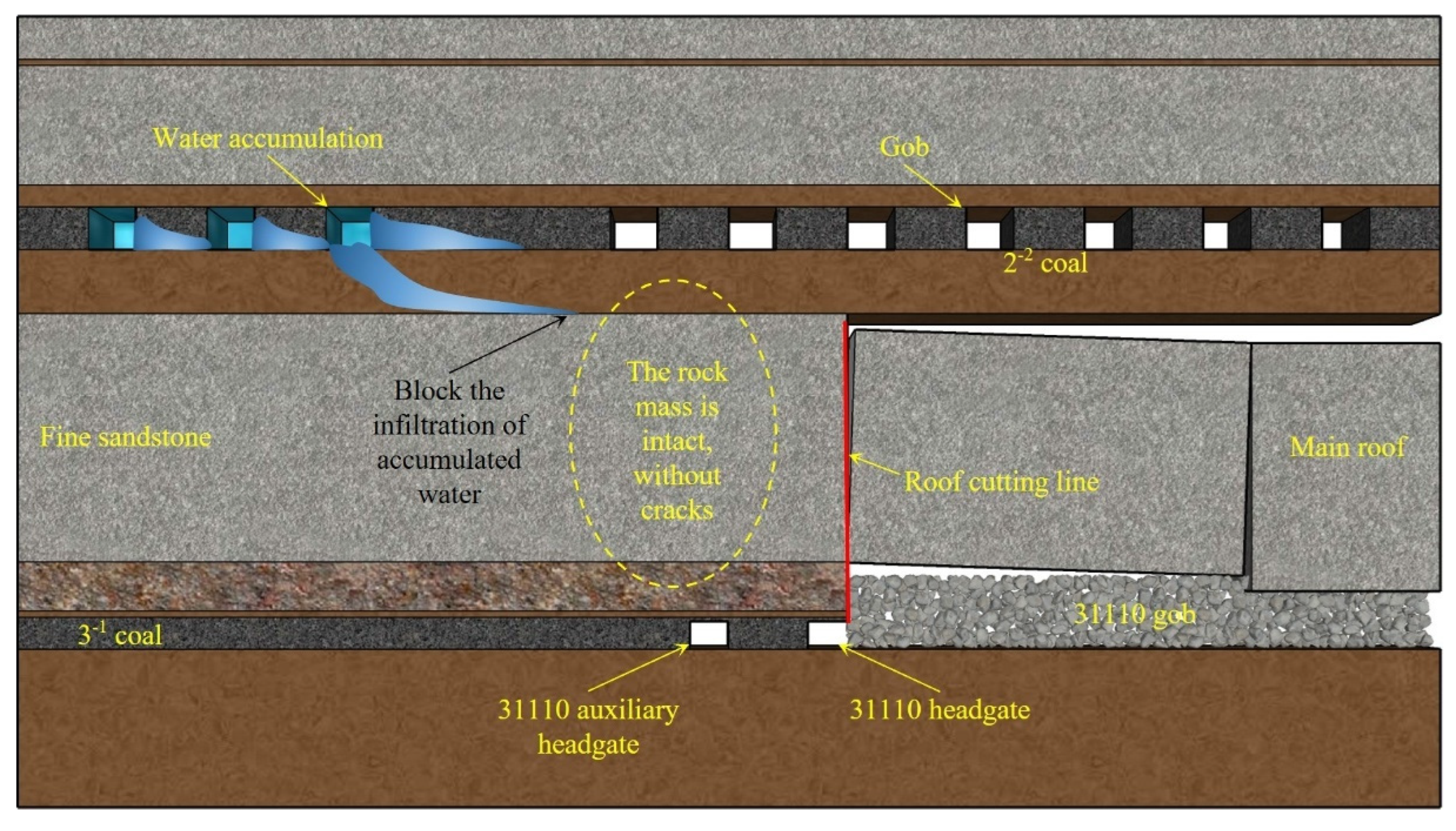
The conceptual framework for controlling gob water accumulation based on roof cutting pressure relief is illustrated in Figure 14. In response to the accumulated water in the gob of the overlying 2−2 coal seam and the mining conditions of the underlying 31110 panel, a roof cutting weakened plane was pre-established on the gob side of the 31110 panel. This approach actively guides the main roof to fracture preferentially toward the gob side [54,55,56], thereby shifting the roof breakage location from the solid coal side above the 31110 auxiliary headgate to the gob side.
Through this controlled intervention, the key aquiclude directly above the roadway is effectively protected from intense mining-induced stress disturbance, allowing it to retain its structural integrity and water-sealing capacity. Under such conditions, even if water accumulated in the overlying 2−2 coal seam gob migrates downward, it is effectively blocked by the intact roof strata above the roadway and is prevented from inrushing into the auxiliary headgate of the underlying 3−1 coal seam. Consequently, the formation and connectivity of water-conducting channels are fundamentally eliminated, achieving effective prevention and control of water inrush hazards.
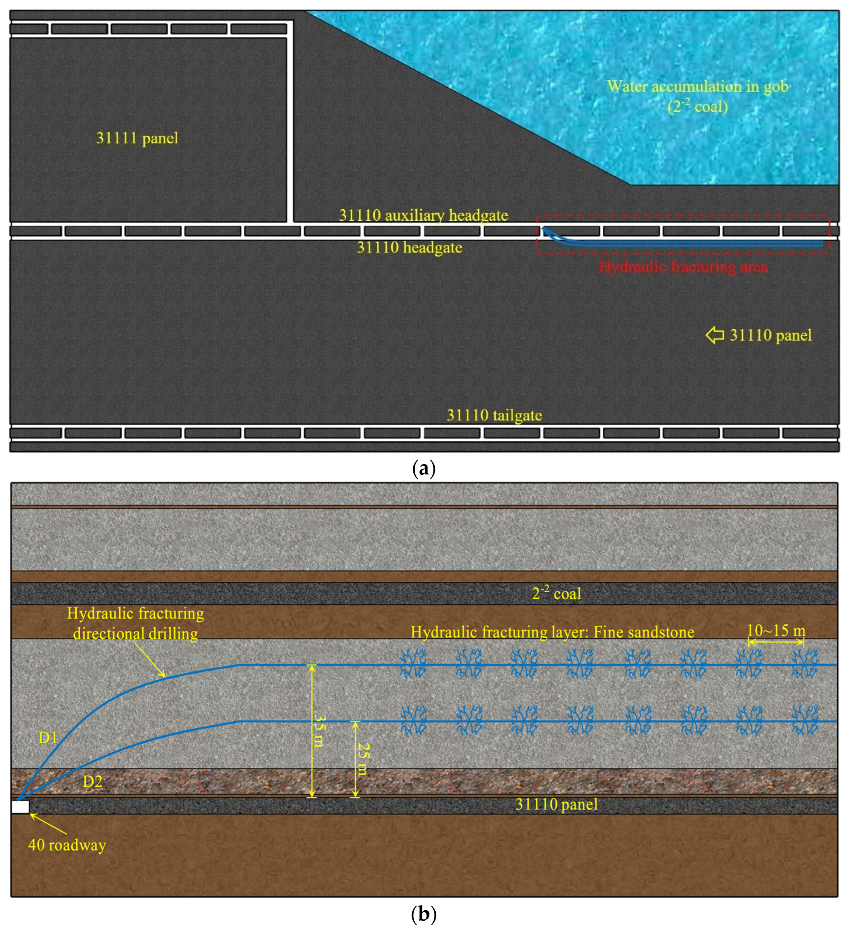
Considering the results of numerical simulation and field implementation, the roof cutting height is finally determined to be 35 m. The hydraulic fracturing scheme is shown in Figure 15. Two sets of directional boreholes were employed for hydraulic fracturing to implement roof cutting and pressure relief. The borehole heights were designed as 25 m and 35 m, respectively, and a retreating fracturing sequence was adopted, with fracturing points spaced at intervals of 10–15 m. The effective fracture propagation radius generated by hydraulic fracturing was approximately 8–10 m, which is sufficient to ensure effective fracturing of the main roof.

5.2. Application Performance

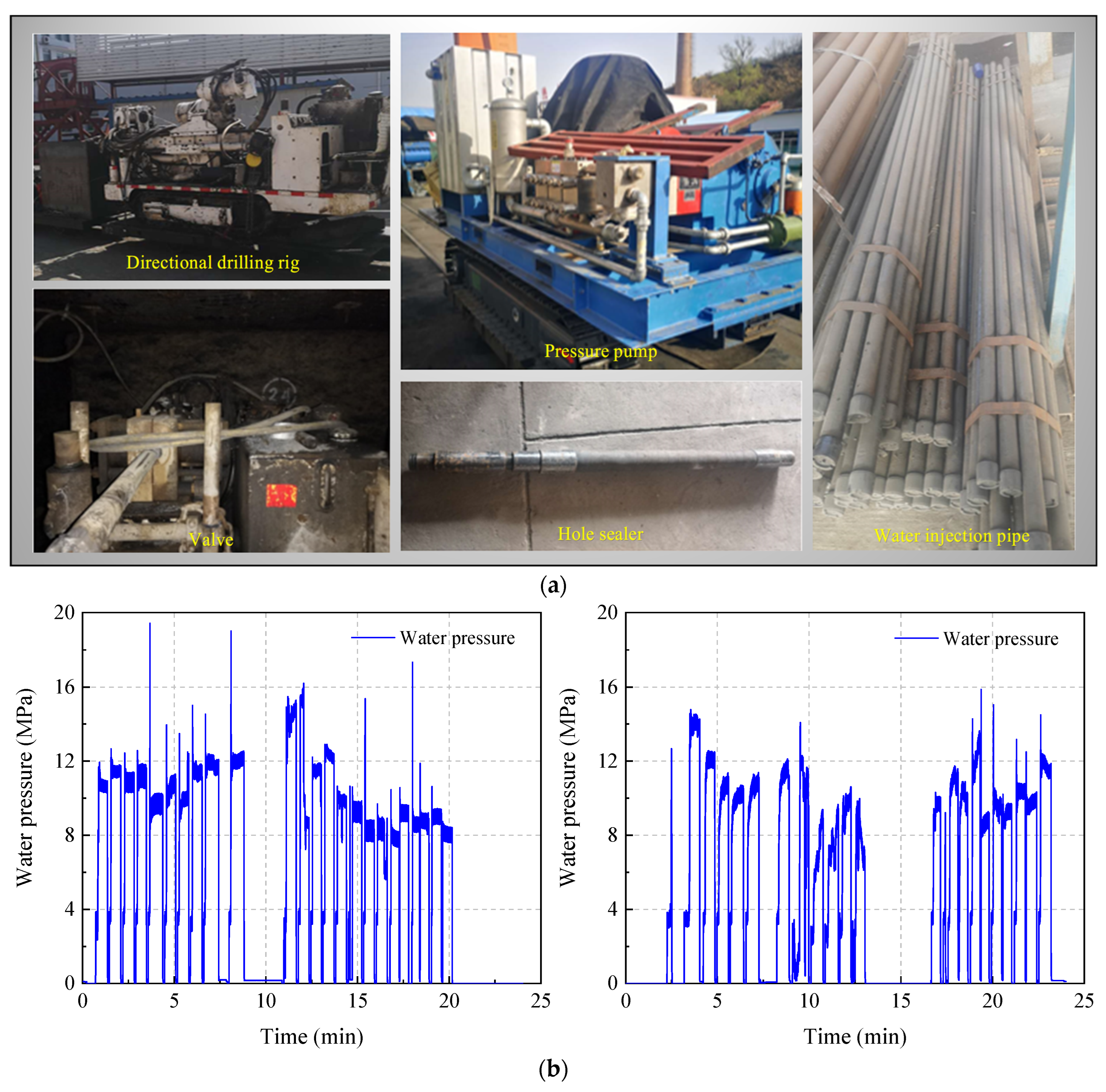
The equipment used for hydraulic fracturing roof cutting is shown in Figure 16a, consisting primarily of a directional drilling rig, a high-pressure grouting pump, control valves, packers, and water injection pipelines. Directional boreholes were drilled at the designed locations using the directional drilling rig, after which the segmented fracturing device was lowered to the target stratigraphic horizon. The packer system was then activated to achieve effective sealing of the designated fracturing interval. Subsequently, the high-pressure fracturing pump was started to inject water into the borehole, and the injection pressure was continuously increased to the pre-set value. Once the threshold pressure was reached, the one-way valve of the packer opened, initiating fracturing of the first segment. High-pressure water injection caused a rapid increase in pore pressure within the rock mass; when the pore pressure exceeded the tensile strength of the rock, a new hydraulic fracture network was generated, resulting in a significant reduction in the overall integrity and strength of the roof strata. After completion of a single fracturing stage, the pump was stopped, and pressure was released, allowing the packer to reset automatically. The drilling rig then retracted the equipment to the next designed position, and the above process was repeated. Upon completion of all the fracturing stages designed, the equipment was fully retrieved.
Following implementation of hydraulic fracturing and roof cutting, the on-site fracturing pressure curves are presented in Figure 16b. The initiation pressure of hydraulic fractures at the 31110 panel ranged from approximately 13 to 20 MPa. Under continuous pressurization by the high-pressure pump, fractures continued to propagate and expand, ensuring the effectiveness and stability of the fracturing operation.
After completion of hydraulic fracturing, borehole camera inspections were conducted in both the fractured zone on the gob side and the unfractured roof area on the solid coal side to verify the roof weakening effect and assess rock mass integrity. The observed fracture distributions from borehole imaging are shown in Figure 17.
The inspection results indicate that, in the fractured zone, the borehole walls exhibit distinct axial hydraulic fractures with good continuity and strong directional characteristics. These fractures effectively weakened the mechanical properties of the local roof rock mass and disrupted its original structural integrity. In contrast, the borehole walls in the unfractured zone on the solid coal side remained intact, with no obvious fracture development observed.
These observations further demonstrate that the roof cutting measure successfully guided the main roof to fracture toward the gob side, thereby effectively preserving the integrity of the key interlayer aquiclude. No through-going fractures developed within the interlayer strata, which effectively blocked the downward seepage pathways of accumulated water from the overlying gob. Field observations thus confirm the effectiveness of hydraulic fracturing, roof cutting, and pressure relief in preventing water inrush hazards induced by gob water accumulation.
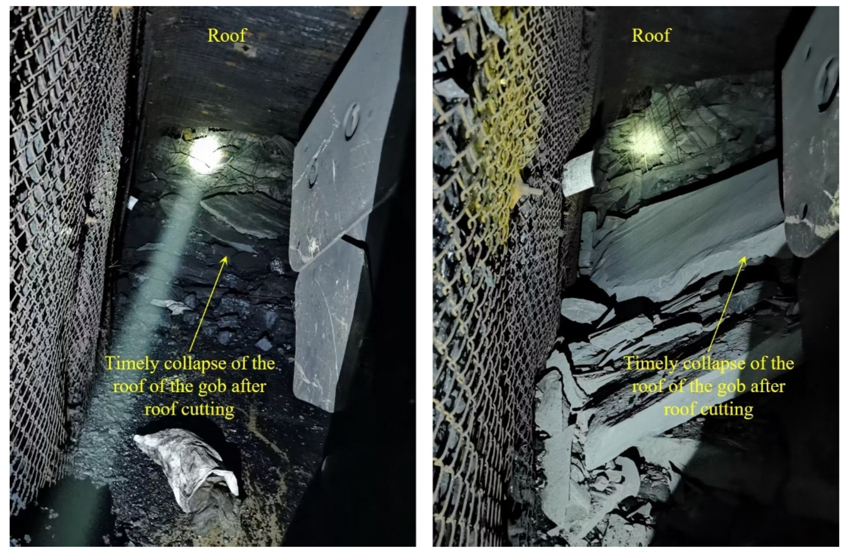
As shown in Figure 18, after the implementation of directional hydraulic fracturing and roof cutting, observations during retreat mining of the 31110 panel revealed that the roof collapsed in a controlled and regular manner along the predefined fracturing trajectories. The caving angle of the overlying strata increased from the original 70° to approximately 90°, effectively suppressing the lateral propagation of mining-induced fractures toward the solid coal pillar region. This significantly inhibited further fracture extension into the coal–rock mass beyond the mining boundary, thereby verifying the active control capability of this technique on overburden movement and lateral fracture development.

6. Conclusions

The findings not only enrich the theoretical understanding of water inrush mechanisms under coal seam group mining but also provide a practical reference for the engineering design and implementation of targeted water hazard control measures in similar geological and mining conditions. The main conclusions are as follows:
(1)
Both theoretical calculations and in situ measurements demonstrate that the maximum seepage depth of the floor induced by mining of the upper 2−2 coal seam (2.43 m), when superimposed with the failure ranges generated by mining of the lower 3−1 coal seam—including the caving zone (10.01–20.01 m) and the water-conducting fractured zone (49.92–67.72 m)—results in a combined damage depth of 62.36–90.16 m. This value far exceeds the actual interlayer spacing of 46.5 m between the two seams, satisfying the conditions for the formation of interconnected water-conducting pathways. Therefore, through-going damage of the interlayer strata is the fundamental prerequisite for water inrush induced by accumulated gob water.
(2)
Numerical simulation results indicate that, under the condition without roof cutting, the main roof fractures on the solid coal side of the auxiliary transportation roadway, causing full connectivity of the overburden plastic zones and forming a continuous water-conducting channel. After the implementation of roof cutting pressure-relief measures, the pre-induced artificial weak plane effectively guides the main roof to fracture toward the gob side. With increasing roof cutting height, the extent of the plastic zone is significantly reduced, its connectivity is weakened, stress distribution becomes more uniform, and strata deformation is markedly suppressed. When the roof cutting height reaches 35 m or greater, the plastic connectivity between the water-resisting coal pillar and the underlying mining-induced damage zone is completely severed, effectively blocking the water-conducting pathway.
(3)
Field application demonstrates that directional hydraulic fracturing roof cutting can effectively regulate the spatial evolution of overburden fractures in coal seam group mining areas characterized by short interlayer spacing and high gob-water accumulation risk. Continuous and strongly oriented hydraulic fracture weak planes are formed within the target roof cutting zone, while the rock mass on the solid coal side remains relatively intact, with no significant fracture development. As a result, the main roof collapses in a controlled manner along the predefined fracturing trajectory, and the caving angle of the overburden increases from approximately 70° to nearly 90°. This controlled structural response effectively suppresses the lateral propagation of mining-induced fractures toward the solid coal pillar, blocks potential water-conducting pathways connecting the overlying 2−2 coal seam gob and the underlying roadway and significantly reduces the risk of catastrophic water inrush. From a geographic and socio-environmental perspective, this technology provides a reliable engineering solution for water hazard prevention in similar mining regions, contributing to safer production, protection of underground space, and sustainable resource exploitation.

Author Contributions

Y.Z.: Writing—original draft; G.Z.: Supervision; X.W. (Xiangyu Wang): Project administration; D.C.: Software, Methodology, Data curation; X.W. (Xian Wang): Visualization; Y.C.: Resources. All authors have read and agreed to the published version of the manuscript.

Funding

This research was financially supported by Coal-Major Project (2025ZD1700600), National Key Research and Development Program of China (2023YFC2907600), National Natural Science Foundation of China (52174132).

Data Availability Statement

Data will be made available on request.

Conflicts of Interest

Author Yongqiang Zhang was employed by the company Shendong Tianlong Group Huoluowan Coal Mine. Author Guochuan Zhang was employed by the company Pingdingshan Tianan Coal Mining Co., Ltd. The remaining authors declare that the research was conducted in the absence of any commercial or financial relationships that could be construed as a potential conflict of interest.

References

  1. Wu, X.; Zhang, Y.; Lai, K.; Yang, M.; Yang, G.-L.; Wang, H. A Novel Centralized Federated Deep Fuzzy Neural Network with Multi-objectives Neural Architecture Search for Epistatic Detection. IEEE Trans. Fuzzy Syst. 2025, 33, 94–107. [Google Scholar] [CrossRef] [Scilit]
  2. Lv, C.; Lv, X.; Wang, Z.; Zhao, T.; Tian, W.; Zhou, Q.; Zeng, L.; Wan, M.; Liu, C. A focal quotient gradient system method for deep neural network training. Appl. Soft Comput. 2025, 184, 113704. [Google Scholar] [CrossRef] [Scilit]
  3. Zhang, L.; Duan, Y.; Wang, Y.; Pineda, E.; Yang, Y.; Pelletier, J.-M.; Wada, T.; Kato, H.; Crespo, D.; Qiao, J. Creep and recovery behavior of metallic glasses in a global strain approach within transition state theory. Acta Mech. Sin. 2026, 42, 425311. [Google Scholar] [CrossRef] [Scilit]
  4. Lv, C.; Cao, Y.; Feng, Y.; Fan, L.; Zhang, J.; Song, Y.; Liu, H.; Gao, G. Crosslinked Vinyl-Capped Polyoxometalates to Construct a Three-Dimensional Porous Inorganic–Organic Catalyst to Effectively Suppress Polysulfide Shuttle in Li–S Batteries. Adv. Energy Mater. 2025, e05978. [Google Scholar] [CrossRef] [Scilit]
  5. Liu, B.; Chen, D.; Xu, C. Deep-hole blasting roof cutting technology for pressure relief in the final mining phase of the working face: A case study. Front. Earth Sci. 2025, 13, 1566968. [Google Scholar] [CrossRef] [Scilit]
  6. Cheng, W.J.; Yin, H.Y.; Xie, D.L.; Dong, F.Y.; Li, Y.J.; Zhu, T.; Wang, J. Prediction of dominant roof water inrush windows and analysis of control target area based on set pair variable weight—Forward correlation cloud model. J. Clean. Prod. 2024, 483, 144253. [Google Scholar] [CrossRef] [Scilit]
  7. Zheng, X.Z.; Li, Y.; Tong, X.; Liu, Q.Y. Precise quantitative evaluation of the risk level of coal mine water inrush accidents based on the CW-BN model. Earth Sci. Inform. 2025, 18, 315. [Google Scholar] [CrossRef] [Scilit]
  8. Zhao, B.X.; Liu, Q.M.; Zhu, J.Z. Risk Assessment and Zonation of Roof Water Inrush Based on the Analytic Hierarchy Process, Principle Component Analysis, and Improved Game Theory (AHP-PCA-IGT) Method. Sustainability 2023, 15, 11375. [Google Scholar] [CrossRef] [Scilit]
  9. Chen, D.; Wang, X.; Zhang, F.; Bai, J.; Zhao, X.; Li, M.; Yu, Y.; Wang, X.; Sun, S. Study on the Mechanism of Progressive Instability of Special-Shaped Coal Pillar and the Stability Control of Roadway Under the Influence of Mining. Rock Mech. Rock Eng. 2024, 57, 6461–6483. [Google Scholar] [CrossRef] [Scilit]
  10. Du, Z.L.; Wu, Q.; Zhao, Y.W.; Zhang, X.Y.; Yao, Y. A multi-constraint and multi-objective optimization layout method for a mine water inrush monitoring network. Sci. Rep. 2023, 13, 11817. [Google Scholar] [CrossRef] [Scilit]
  11. Gai, Q.K.; Gao, Y.B.; Zhang, X.X.; He, M.C. A New Method for Evaluating Floor Spatial Failure Characteristics and Water Inrush Risk Based on Microseismic Monitoring. Rock Mech. Rock Eng. 2024, 57, 2847–2875. [Google Scholar] [CrossRef] [Scilit]
  12. Gao, W.F.; Cao, Y.N.; Dong, X.F. Risk Assessment of Water Inrush from Coal Seam Floor with a PCA-RST Algorithm in Chenmanzhuang Coal Mine, China. Water 2024, 16, 3269. [Google Scholar] [CrossRef] [Scilit]
  13. Guo, J.S.; Ma, L.Q. Permeability Distribution Characteristics and Water Resistance Evaluation of Interlayer Rock Strata During Multi-seam Coal Mining. Mine Water Environ. 2025, 44, 239–258. [Google Scholar] [CrossRef] [Scilit]
  14. Liu, Q.T.; Xu, J.; Wang, Q.Q.; Li, W.P. Risk Assessment of Water Inrush from Coal Seam Roof Based on the Combined Weighting of the Geographic Information System and Game Theory: A Case Study of Dananhu Coal Mine No. 7, China. Water 2024, 16, 710. [Google Scholar] [CrossRef] [Scilit]
  15. Liu, S.L.; Wang, A.; Mu, D.R.; Zheng, Y.S.; Wang, S.L.; Liu, Y. A new analytical solution method of water inrush risk for an inclined coal floor above a confined aquifer. Environ. Earth Sci. 2024, 83, 87. [Google Scholar] [CrossRef] [Scilit]
  16. Niu, C.; Tian, Q.F.; Xiao, L.L.; Xue, X.C.; Zhang, R.Q.; Xu, D.J.; Luo, S.T. Principal causes of water damage in mining roofs under giant thick topsoil-lilou coal mine. Appl. Water Sci. 2024, 14, 146. [Google Scholar] [CrossRef] [Scilit]
  17. Sakhno, I.; Zuievska, N.; Xiao, L.; Zuievskyi, Y.; Sakhno, S.; Semchuk, R. Prediction of Water Inrush Hazard in Fully Mechanized Coal Seams’ Mining Under Aquifers by Numerical Simulation in ANSYS Software. Appl. Sci. 2025, 15, 4302. [Google Scholar] [CrossRef] [Scilit]
  18. Wang, D.D.; Sui, W.H.; Ji, Z.Q.; Cheng, Y.H. Dynamic hazard analysis and mechanism of groundwater inrush under complex geological structures. Tunn. Undergr. Space Technol. 2025, 165, 106884. [Google Scholar] [CrossRef] [Scilit]
  19. Sun, Z.; Yu, K.; Zhen, Z.; Raza, A.; Lv, J. Control mechanism of regional structure on geothermal water chemistry, geothermal field and thermal hazard in a coal mine. Geoenergy Sci. Eng. 2026, 256, 214164. [Google Scholar] [CrossRef] [Scilit]
  20. Huang, Z.D.; Wang, K.; Liu, X.S.; Zhao, Y.Q.; Li, X.B.; Fu, B.; Zhou, Y. Risk Identification Method and Application of Roof Water Inrush Under Multi-Working Face Mining. Appl. Sci. 2025, 15, 3511. [Google Scholar] [CrossRef] [Scilit]
  21. Ji, Y.; Yu, L.J.; Wei, Z.L.; Ding, J.; Dong, D.L. Research Progress on Identification of Mine Water Inrush Sources: A Visual Analysis Perspective. Mine Water Environ. 2025, 44, 3–15. [Google Scholar] [CrossRef] [Scilit]
  22. Jiang, P.F.; Zhuge, F.M.; Jing, S.L.; Li, Z.K.; Xiao, P.; Lv, Y.G. Roof Water Damage Prediction and Evaluation of Sand-Mud Sedimentary Tectonic Strata. Geofluids 2023, 2023, 2243885. [Google Scholar] [CrossRef] [Scilit]
  23. Jiao, H.; Lun, Z.J.; Ni, Y.X.; Chang, Z.G.; Fan, L.M.; Ma, L.Q. Evaluation of Water-Inrush Risk and Water-Preserved Mining Under Goaf Water. Water 2025, 17, 1734. [Google Scholar] [CrossRef] [Scilit]
  24. Zhang, F.D. Dynamic Monitoring and an Early Warning Model of a Floor Water Disaster: A Case Study. Mine Water Environ. 2023, 42, 158–169. [Google Scholar] [CrossRef] [Scilit]
  25. Yu, S.; Ding, H.H.; Yang, M.Y.; Zhang, M.L. Evaluation of Water Inrush Risk in the Fault Zone of the Coal Seam Floor in Madaotou Coal Mine, Shanxi Province, China. Water 2025, 17, 259. [Google Scholar] [CrossRef] [Scilit]
  26. Yin, H.C.; Zhang, G.Z.; Wu, Q.; Yin, S.X.; Soltanian, M.R.; Thanh, H.V.; Dai, Z.X. A Deep Learning-Based Data-Driven Approach for Predicting Mining Water Inrush from Coal Seam Floor Using Microseismic Monitoring Data. IEEE Trans. Geosci. Remote Sens. 2023, 61, 4504815. [Google Scholar] [CrossRef] [Scilit]
  27. Xue, Y.; Zhu, S.Y.; Qiu, H.M. Refinement Study on the Water-Inrush Risk of Close-Distance Thin Coal Seam Mining with Pressure in the Lower Coal Seam. Mine Water Environ. 2023, 42, 670–686. [Google Scholar] [CrossRef] [Scilit]
  28. Xiao, L.L.; Li, F.; Niu, C.; Dai, G.L.; Qiao, Q.; Lin, C.S. Evaluation of Water Inrush Hazard in Coal Seam Roof Based on the AHP-CRITIC Composite Weighted Method. Energies 2023, 16, 114. [Google Scholar] [CrossRef] [Scilit]
  29. Wu, F.Z.; Du, J.M.; Sun, F.X.; Chen, G.; Jiang, F.J.; Zhu, Z.Q. Multi-method Coal Seam Floor Water Inrush Risk Evaluation Based on Variable Weight Theory. Energy Explor. Exploit. 2025, 43, 724–743. [Google Scholar] [CrossRef] [Scilit]
  30. Chen, D.; Wang, X.; Bai, J.; Li, M. Characteristics of waterproof failure and optimal width of narrow coal pillars under the coupled effects of mining, excavation and seepage. Geomech. Geophys. Geo-Energy Geo-Resour. 2024, 10, 100. [Google Scholar] [CrossRef] [Scilit]
  31. Dong, F.Y.; Yin, H.Y.; Chen, S.J.; Xie, D.L.; Zhou, W.F.; Han, C.H.; Wei, J.C.; Wang, F.H.; Wu, T. Innovative groundwater disaster prevention and control systems for ultrawide working face mining in deeply buried confined aquifers. J. Hydrol. 2025, 663, 134244. [Google Scholar] [CrossRef] [Scilit]
  32. Wang, D.D.; Sui, W.H.; Ranville, J.F. Hazard identification and risk assessment of groundwater inrush from a coal mine: A review. Bull. Eng. Geol. Environ. 2022, 81, 421. [Google Scholar] [CrossRef] [Scilit]
  33. Dong, F.Y.; Yin, H.Y.; Feng, Q.F.; Li, S.; Zhou, W.; Cheng, W.J.; Qiu, M.; Shi, Y.L.; Jia, C.W. A new insight of water inrush mode and coal (rock) pillars setting in near-fault mining under high confined water. J. Appl. Geophys. 2023, 216, 105136. [Google Scholar] [CrossRef] [Scilit]
  34. Hao, Y.; Yang, H.H.; Zhang, L.J.; Sun, C.L. Study on the Effectiveness of the Integral Emergency Response System for Coal Mine Water Hazard Accidents Based on Combination Weighting. Processes 2024, 12, 235. [Google Scholar] [CrossRef] [Scilit]
  35. Wang, P.P.; Jiang, Y.D.; Ren, Q.S. Roof Hydraulic Fracturing for Preventing Floor Water Inrush under Multi Aquifers and Mining Disturbance: A Case Study. Energies 2022, 15, 1187. [Google Scholar] [CrossRef] [Scilit]
  36. Long, T.W.; Hou, E.K.; Xie, X.S.; Fan, Z.G.; Tan, E.M. Study on the damage characteristics of overburden of mining roof in deeply buried coal seam. Sci. Rep. 2022, 12, 11141. [Google Scholar] [CrossRef] [Scilit]
  37. Xie, D.L.; Du, Z.W.; Han, C.H.; Han, J.; Wei, J.C.; Yan, J.L. Prediction of the Water Inrush Risk from an Overlying Separation Layer in the Thick Overburden of a Thick Coal Seam. Sustainability 2023, 15, 13988. [Google Scholar] [CrossRef] [Scilit]
  38. Shi, X.C.; Lyu, G. Mechanism of Bed Separation Water Inrush during the Mining of Extra-Thick Coal Seam under Super-Thick Sandstone Aquifer. Sustainability 2023, 15, 10599. [Google Scholar] [CrossRef] [Scilit]
  39. Liu, R.; Zhi, G.J.; Yang, S.L.; Xu, X.W. Investigation on Mining-Induced Floor Water Inrush from Column and Its Control Based on Microseismic Monitoring. Adv. Civ. Eng. 2023, 2023, 3754079. [Google Scholar] [CrossRef] [Scilit]
  40. Xing, S.H.; Li, M.; Wang, Y.F.; Ma, D.; Sun, Z.H.; Peng, Y.F. Effect of backfill ratio on the risk of water inrush in goaf backfilling of coal gangue under aquifer. Environ. Earth Sci. 2025, 84, 542. [Google Scholar] [CrossRef] [Scilit]
  41. Sun, X.; Lu, M.; Li, C. Optimization of staggered distance of coal pillars in multiseam mining: Theoretical analysis and numerical simulation. Energy Sci. Eng. 2021, 9, 357–374. [Google Scholar] [CrossRef] [Scilit]
  42. Liu, Y.; Zhu, Q.; Wei, Q.; Yang, G.; Zhang, Y.; Hao, Q.; Jiang, D. Theoretical framework and reliability verification of the loaded three-zone structural model in coal mine overburden strata. Sci. Rep. 2025, 15, 35359. [Google Scholar] [CrossRef] [Scilit]
  43. Zhang, L.; Zhang, Z.; Wang, K.; Tan, X.; Zhang, L.; Zhang, T. Development and Height Prediction of Fractured Water-Conducting Zone in Weakly Cemented Overburden: A Case Study of Tashidian Erjingtian Mine. Sustainability 2023, 15, 13899. [Google Scholar] [CrossRef] [Scilit]
  44. Abdulwarith, A.; Ammar, M.; Kakadjian, S.; McLaughlin, N.; Dindoruk, B. A hybrid physics augmented predictive model for friction pressure loss in hydraulic fracturing process based on experimental and field data. Geoenergy Sci. Eng. 2026, 257, 214212. [Google Scholar] [CrossRef] [Scilit]
  45. Chen, D.C.; Wang, X.Y.; Bai, J.B.; Chu, Y.; Wang, X.; Zhao, J.X.; Li, M.L. An overview of ahead geological detection technologies in tunnels. Eur. J. Remote Sens. 2025, 58, 2503240. [Google Scholar] [CrossRef] [Scilit]
  46. Chen, D.C.; Wang, X.Y.; Bai, J.B.; Zhang, F.T.; Chu, Y.; Wang, X.; Sun, G.J. Research on extension mechanism of directional hydraulic fracture under abutment stress based on XFEM. Geoenergy Sci. Eng. 2026, 257, 214230. [Google Scholar] [CrossRef] [Scilit]
  47. Zhu, Q.W.; Xue, F.; Bai, G.C.; Li, T.C.; Wang, B.X.; Zhao, J.W. An exploration of improving the stability of mining roadways constructed in soft rock by roof cutting and stress transfer: A case study. Eng. Fail. Anal. 2024, 157, 26. [Google Scholar] [CrossRef] [Scilit]
  48. Jiang, L.; Zhang, P.; Chen, L.; Hao, Z.; Sainoki, A.; Mitri, H.S.; Wang, Q. Numerical Approach for Goaf-Side Entry Layout and Yield Pillar Design in Fractured Ground Conditions. Rock Mech. Rock Eng. 2017, 50, 3049–3071. [Google Scholar] [CrossRef] [Scilit]
  49. Li, Y.; Wang, N.; Lei, X.; Li, T.; Ren, Y.; Jin, X. Stress Evolution of Repeated Mining Based on the Double-Yield Model in Multiple Coal Seam. Rock Mech. Rock Eng. 2024, 57, 2809–2827. [Google Scholar] [CrossRef] [Scilit]
  50. Zhang, G.; He, F.; Jia, H.; Lai, Y. Analysis of Gateroad Stability in Relation to Yield Pillar Size: A Case Study. Rock Mech. Rock Eng. 2017, 50, 1263–1278. [Google Scholar] [CrossRef] [Scilit]
  51. Chen, D.C.; Wang, X.Y.; Bai, J.B.; Zhang, F.T. Deformation mechanism and control technology of gob-side roadway with continuous mining and continuous backfilling: A case study. Geomat. Nat. Hazards Risk 2024, 15, 2350480. [Google Scholar] [CrossRef] [Scilit]
  52. Chen, D.C.; Wang, X.Y.; Zhao, J.X.; Bai, J.B.; Chu, Y.; Zhou, Q.C.; Yu, Y. Research on the stability mechanism and control technique of surrounding rock in gob side entry driving. Sci. Rep. 2025, 15, 34676. [Google Scholar] [CrossRef] [Scilit]
  53. Chen, D.; Wang, X.; Zhang, F.; Li, M.; Zhao, X.; Li, G.; Yu, Y.; Wang, G.; Zhao, J.; Wang, X. Research on Directional Controllability of Cracking in Hydraulic Fracturing of Hard Overburden Based on Local Stress Field Intervention. Energies 2022, 15, 4252. [Google Scholar] [CrossRef] [Scilit]
  54. Li, G.; Gao, L.; Ma, Q.; Liu, H. Research on the optimization and application of coal pillar width in gob-side entry driving under hard roof condition. Front. Earth Sci. 2025, 13, 1603252. [Google Scholar] [CrossRef] [Scilit]
  55. Wu, W.; Wang, T.; Bai, J.; Liu, J.; Wang, X.; Xu, H.; Feng, G. Failure Characteristics and Cooperative Control Strategies for Gob-Side Entry Driving near an Advancing Working Face: A Case Study. Processes 2024, 12, 1398. [Google Scholar] [CrossRef] [Scilit]
  56. Xie, S.; Wu, Y.; Guo, F.; Zou, H.; Chen, D.; Zhang, X.; Ma, X.; Liu, R.; Wu, C. Application of Pre-Splitting and Roof-Cutting Control Technology in Coal Mining: A Review of Technology. Energies 2022, 15, 6489. [Google Scholar] [CrossRef] [Scilit]
Figure 1. Statistics of coal mine water-related accidents in China [30].
Applsci 16 01970 g001
Figure 2. Mine overview: (a) mine location; (b) stratigraphic column.
Applsci 16 01970 g002
Figure 3. Working face layout: (a) plan view; (b) cross-sectional view.
Applsci 16 01970 g003
Figure 4. Exploration of water accumulation in the gob.
Applsci 16 01970 g004
Figure 5. Floor-seepage depth induced by mining of the 2−2 coal seam.
Applsci 16 01970 g005
Figure 6. Height of the roof water-conducting fracture zone induced by mining of the 3−1 coal seam.
Applsci 16 01970 g006
Figure 7. Connectivity between water-conducting channels and fracture zones.
Applsci 16 01970 g007
Figure 8. Numerical model: (a) boundary conditions; (b) stratigraphic division; (c) roadway distribution; (d) stress distribution of surrounding rock after roadway excavation.
Applsci 16 01970 g008
Figure 9. Numerical simulation procedure.
Applsci 16 01970 g009
Figure 10. Comparison of plastic zone distributions: (a) no roof cutting; (b) roof cutting height of 25 m; (c) roof cutting height of 35 m; (d) roof cutting height of 45 m.
Applsci 16 01970 g010
Figure 11. Comparison of vertical stress distributions: (a) no roof cutting; (b) roof cutting height of 25 m; (c) roof cutting height of 35 m; (d) roof cutting height of 45 m.
Applsci 16 01970 g011
Figure 12. Vertical stress curves of the overlying strata.
Applsci 16 01970 g012
Figure 13. Deformation of the overlying strata: (a) vertical displacement; (b) horizontal displacement.
Applsci 16 01970 g013
Figure 14. Conceptual framework for water inrush control.
Applsci 16 01970 g014
Figure 15. Hydraulic fracturing scheme: (a) plan view; (b) cross-sectional view.
Applsci 16 01970 g015
Figure 16. Hydraulic fracturing conditions: (a) hydraulic fracturing equipment; (b) hydraulic fracturing pressure curves.
Applsci 16 01970 g016
Figure 17. Borehole imaging results of fracture distribution.
Applsci 16 01970 g017
Figure 18. On-site roof-caving characteristics.
Applsci 16 01970 g018
Table 1. Empirical formulas for estimating the height of the water-conducting fracture zone [43].
Laboratory Uniaxial Compressive Strength/MPaRock StrengthLithologyMaximum Height of Water-Conducting Fracture Zone/m
40~80HardQuartz sandstone, limestone, conglomerate H f = 100 M 1.2 M + 2.0 ± 8.9
20~40Moderately hardSandstone, argillaceous limestone, sandy shale, shale H f = 100 M 1.6 M + 3.6 ± 5.6
10~20SoftMudstone, argillaceous sandstone H f = 100 M 3.1 M + 5.0 ± 4.0
<10Extremely softBauxite, weathered mudstone, clay, sandy clay H f = 100 M 5.0 M + 8.0 ± 3.0
here M is the cumulative mining thickness (m).
Table 2. Mechanical parameters used in the numerical model.
LithologyThickness
(m)
Density
(kg/m3)
Bulk Modulus
(GPa)
Shear Modulus
(GPa)
Cohesion
(MPa)
Friction Angle
(°)
Tensile Strength
(MPa)
Fine sandstone5.426009.055.613.90352.75
Mudstone0.824373.512.122.21301.70
Fine sandstone15.126009.055.613.90352.75
Mudstone2.824373.512.122.21301.70
2−2 coal5.414101.971.071.00250.90
Mudstone8.124373.512.122.21301.70
Fine sandstone31.426009.055.613.90352.75
Siltstone6.225908.255.253.10342.20
Mudstone0.824373.512.122.21301.70
3−1 coal4.014101.971.071.00250.90
Mudstone20.024373.512.122.21301.70
Disclaimer/Publisher’s Note: The statements, opinions and data contained in all publications are solely those of the individual author(s) and contributor(s) and not of MDPI and/or the editor(s). MDPI and/or the editor(s) disclaim responsibility for any injury to people or property resulting from any ideas, methods, instructions or products referred to in the content.