1. Introduction
High-speed railways, as strategic, pioneering, and essential national infrastructure, have become a fundamental pillar of modern transportation systems due to their exceptional operating speed, superior transport efficiency, outstanding safety, and passenger comfort. Globally, the total length of high-speed railway under construction or in planning now exceeds 60,000 km, underscoring the sustained momentum and large-scale expansion of this mode of transport [
1,
2,
3].
Within the core technological framework of high-speed railway construction, the ballastless track system has emerged as the predominant structural form. Its track geometry quality, which is expressed as TQI (Track Quality Index), directly governs train operating safety, riding comfort, attainable speed, and the service life of the track and associated infrastructure [
4]. Consequently, precise and effective control of the track geometry during construction has become a crucial issue for international concern [
5].
Current engineering projects primarily adopt two categories of fine adjustment methods for track smoothness.
In this conventional adjustment process, standard fasteners are first installed along the entire track. The rail geometry is then continuously measured using a total-station system and a track-inspection trolley to generate a corresponding adjustment scheme based on the detected deviations and tolerance limits. Fine alignment is achieved by modifying the combination of shims within the fastener assemblies to correct lateral and vertical rail offsets, ensuring that the track smoothness meets design and acceptance requirements [
6,
7].
Despite its maturity, this approach presents several fundamental drawbacks:
- (a)
Excessive iteration and material waste: repeated measurements and adjustments result in large-scale replacement of fastenings, increased material consumption, and elevated labor intensity and cost.
- (b)
Limited mechanical adjustability: the narrow tunable range of fastenings often leads to incompatibility between local optimization objectives and physical feasibility, resulting in rework or even structural re-opening.
- (c)
Strong dependence on human expertise: adjustment planning and execution rely heavily on field experience, introducing subjectivity, inconsistency, and inefficiency.
- (d)
Lack of global alignment control: localized optimization compromises the consistency of the overall alignment, particularly over long distances.
While this approach remains the mainstream method in practice, its constraints in efficiency, cost, and standardization make it increasingly incompatible with the evolving demands for intelligent, automated, and scientifically guided track adjustment in modern high-speed railway construction.
- 2.
Pre-laying absolute measurement and adjustment
In this category, the rail-top reference line is virtually instantiated prior to continuous welded rail placement by positioning survey prisms on bearing boards and alignment pedestals. High-precision observations of the prism centers are subsequently acquired to infer the rail’s prospective three-dimensional pose and geometric profile. This pre-installation geometric abstraction enables the formulation of a predictive fine-alignment strategy before physical rail installation.
Although this kind of approach offers potential advantages by reducing on-site rework, its actual performance in engineering applications has been less satisfactory, primarily due to the following:
- (a)
Loss of geometric continuity: representing the continuous rail alignment as a sparse set of discrete points introduces interpolation uncertainty, reducing the fidelity of geometric representation.
- (b)
Insufficient spatial fidelity: simplifying the three-dimensional alignment into lateral and elevation deviations impairs spatial reconstruction accuracy, leading to incorrect estimation of fastening adjustment magnitudes.
- (c)
Cumulative error propagation: multi-station data merging with simplistic smoothing or linear compensation often introduces coordinate and elevation inconsistencies in overlapping regions, causing significant cumulative errors and degraded reliability of the final TQI assessment.
Field data demonstrate that the final TQI achieved using this method typically falls between 2 and 4, which fails to meet the stringent acceptance criteria for ballastless track construction. This indicates an inherent conflict between theoretical accuracy and practical feasibility [
8,
9].
To overcome these limitations, this paper introduces a virtual pre-adjustment framework implemented between ballastless track panel concreting and long-rail installation. The framework represents an engineering-oriented, execution-level digital twin that focuses on high-fidelity geometric state representation and physically executable adjustment planning, rather than an enterprise-scale BIM-based digital twin or lifecycle information management system, emphasizing construction-stage geometric consistency and adjustment feasibility rather than semantic completeness or full lifecycle information coverage.
The proposed framework integrates a high-fidelity digital representation of track geometry with constraint-based optimization algorithms, enabling reliable simulation and evaluation of adjustment strategies under realistic engineering constraints. A dual-frame, SLAM-inspired three-dimensional reconstruction strategy is incorporated to enhance spatial continuity and measurement robustness compared with traditional station-based surveying methods. By introducing continuous mapping principles into large-scale engineering measurement, the proposed approach effectively mitigates cumulative errors and improves geometric consistency over long distances.
The final output of the framework is a fully executable fine adjustment plan that can be directly translated into field operations or automated construction tasks. This eliminates the traditional trial-and-error process associated with manual adjustment, significantly reducing material waste, rework frequency, and dependence on field experience. From an engineering workflow, this capability constitutes a key enabling module for the digital transformation of railway construction workflows and future decision support systems.
The key innovations and technical contributions of this paper can be summarized as follows:
A dual-frame measurement method is proposed to address the long-standing trade-off between measurement accuracy and spatial coverage in large-scale ballastless track construction. By integrating SLAM-inspired continuous mapping and multi-dimensional topological reconstruction, cumulative measurement errors are systematically suppressed, enabling high-accuracy digital representation of long-distance track geometry.
A local posture compensation-based fitting model is developed, incorporating a micro-tilt compensation mechanism for rail bearing platforms. This design resolves the mismatch between virtual and physical geometries caused by subtle attitude deviations, providing reliable geometric inputs for precise and feasible virtual adjustment.
The long-rail laying and fine adjustment process is migrated into a digital execution environment. Through high-fidelity geometric modeling and global optimization-based virtual pre-adjustment, a closed-loop pipeline from measurement acquisition to adjustment plan generation is established. This bridges SLAM-derived geometric modeling with engineering-oriented constraint optimization, substantially improving adjustment precision, reproducibility, and construction efficiency, and offering a new paradigm for precision and automated construction in next-generation high-speed railways.
For designers of railway diagnostic equipment, the proposed framework provides actionable insights into measurement-driven adjustment, enabling a shift from reactive detection to proactive geometry control. This capability directly informs sensor deployment, calibration, and operational planning, supporting data-driven asset management workflows. Each of the proposed technical innovations contributes not only to construction-stage precision but also to enabling downstream decision support and asset management, linking methodical improvements to strategic digitalization objectives.
The rest of this paper is organized as follows:
Section 2 introduces the proposed dual-frame SLAM-based measurement approach applied in long-distance railway projects. The local-posture-compensation-based fitting model and complete virtual pre-adjustment process are demonstrated in
Section 3.
Section 4 actualizes and verifies the whole proposed approach in practical engineering. Finally,
Section 5 concludes this paper.
2. High-Precision Dual-Frame SLAM-Based Measurement Approach
As outlined in
Section 1, the virtual pre-adjustment strategy proposed in this paper aims to migrate track-geometry optimization from onsite trial-and-error procedures to an execution-level virtual environment for geometry simulation and adjustment planning rather than a full asset digital twin system, thereby mitigating material waste, reducing repeated rework, and improving construction efficiency. Realizing this transformation requires measurement data that can simultaneously deliver sub-millimeter accuracy and remain globally consistent over long distances. Without such fidelity, the virtual simulation cannot be trusted, nor can the adjustment plan derived from it be executed with confidence in the field.
However, existing measurement technologies reveal inherent limitations in high-speed railway scenarios. Discrete geodetic instruments such as total stations offer high accuracy but present a severe mismatch between measurement granularity and the mechanical adjustment resolution required for sub-millimeter-level rail fine-tuning. Continuous measurement approaches, such as inertial measurement trolleys, suffer significant degradation in accuracy and stability when detached from the physical rail constraint, falling short of the robustness demanded by virtual adjustment systems. Even state-of-the-art methods, including LiDAR and terrestrial 3D scanners, struggle to reconcile accuracy, coverage, and operational efficiency when confronted with the unique constraints of high-speed railway environments characterized by long-distance, large-scale, and high-precision coexistence. These limitations are particularly evident in scenarios analogous to SLAM-based large-scale mapping, where long-range drift, frame misalignment, and loop-closure inconsistencies can severely compromise global accuracy. This observation highlights a core bottleneck in track geometry control: acquiring measurement data that directly supports virtual pre-adjustment at the engineering scale [
10,
11].
It is noteworthy that many 3D sensing technologies have already achieved sub-millimeter accuracy in confined environments and have been commercialized successfully for industrial applications. Nevertheless, global spatial consistency and cumulative error propagation become dominant when these technologies are deployed across the extended spatial domain of high-speed railways. In such GNSS-denied or structure-constrained environments, the absence of reliable global references causes drift behavior analogous to long-horizon SLAM degradation, and without effective mitigation of these effects, the performance of virtual pre-adjustment will deteriorate rapidly, undermining its practical value.
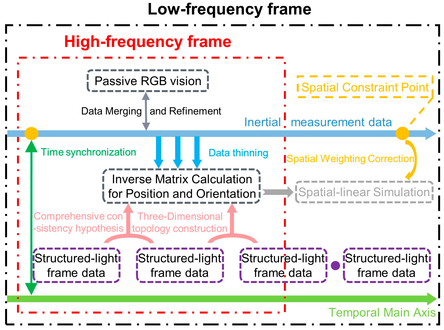
Motivated by the robustness principles of modern SLAM systems, particularly hierarchical mapping, error-bounded graph optimization, and local-to-global fusion, we introduce a segmentation-based hierarchical modeling approach as shown in
Figure 1. This approach integrates local topological reconstruction with global fusion, which enables accurate modeling of long-distance track geometry while effectively suppressing cumulative errors [
12,
13]. We refer to this approach as RC-SLAM (Railway-Constraint SLAM) to emphasize its error-suppression and map-consistency mechanisms inspired by SLAM theory. The proposed method does not aim to develop a generic SLAM algorithm but adopts selected continuous-mapping and error-suppression principles for engineering measurement.
Meanwhile, structured-light binocular vision is adopted as the local high-precision sensing modality under this framework. This technique provides dense point-cloud measurements and rich texture information with excellent scalability, forming a robust foundation for long-range geometric fusion and track surface modeling. Its dense–local characteristics complement the sparse–global constraints in RC-SLAM, yielding a hybrid sensing paradigm similar to multi-sensor fusion SLAM systems.
Furthermore, we develop three parallel topological reconstruction strategies to jointly achieve fine-grained local representation and globally continuous geometric expression. These strategies ensure that the measurement data serve as a reliable backbone for virtual pre-adjustment and simulation-driven track-smoothness control, thereby enabling a credible and engineering-oriented digital calibration pipeline, serving as the geometric data backbone for execution-level virtual pre-adjustment [
14].
2.1. Temporal Topology Construction Strategy
Railways and their associated infrastructure represent a class of large-scale, highly regular, and line-structured industrial systems. Such geometric regularity, coupled with strict construction tolerances, implies that the motion trajectory of inertial or mobile measurement platforms is strongly correlated with the topological unfolding of three-dimensional data. In other words, the inherently stable and continuous temporal dimension serves as a reliable structural prior, ensuring both sparse-state confidence and global unbiasedness during measurement and spatial reconstruction.
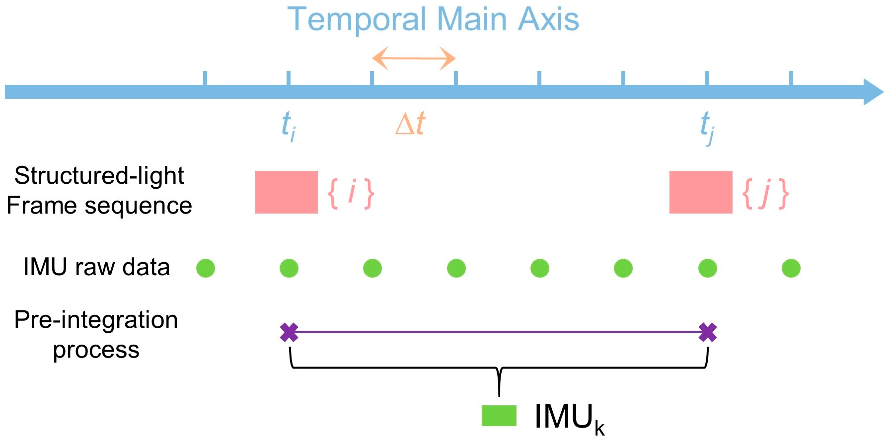
In the proposed measurement configuration, multiple time-indexed data streams are generated, including the structured-light sampling timeline, camera exposure timeline, and system motion-pose timeline. Among these, the acquisition timestamps of the structured-light point cloud, which are characterized by higher instantaneous spatial resolution and richer geometric attributes, are designated as the primary temporal reference axis. To ensure coherent fusion of heterogeneous data modalities sampled at different frequencies, a temporal integration scheme is employed to synchronize motion-state information and imaging events onto this reference axis (as illustrated in
Figure 2). This synchronization mechanism resembles multi-rate sensor fusion in SLAM systems, ensuring that the dual-frame architecture preserves both temporal coherence and geometric fidelity. The time-anchored fusion mechanism establishes a continuous and globally consistent temporal topology for subsequent large-scale geometric reconstruction [
15].
To further enhance measurement accuracy, it is necessary to incorporate the camera exposure time inherent to the structured-light imaging process. Accordingly, we define the minimum envelope interval during which one complete pose estimate and one structured-light frame are acquired as a refinement cycle. Within each refinement cycle, a linear correction is applied based on two fundamental priors, including irradiance consistency of the structured-light projection
and local surface consistency of the reconstructed target
[
16].
First, let the system pose at
time correspond to frame image
, which is then temporally propagated to the two endpoints of the refinement cycle, denoted as
and
. Taking the beginning of the refinement cycle as an example, during the correction process the algorithm maps pixel
in the frame image
to its corresponding pixel
in the frame image
, together with its adjacent offset hypotheses
and
. Based on the normalized cross-correlation metric and the reference responses
,
and
, the following formulation is derived:
Meanwhile, enforcing surface consistency under the disparity-smoothness constraint yields
In this formulation, the weight updates explicitly preserve the intrinsic anisotropy of the equations, thereby mitigating over-smoothing effects in regions with discontinuous depth structures
Taking both constraints jointly, the total consistency term
is reformulated as
where
denotes a user-defined smoothing regularization coefficient.
Finally, the linearly regressed matching term
can be expressed as
where
denotes the matching cost associated with the target depth, and
and
represent the matching costs of the neighboring depth hypotheses corresponding to the lower and higher candidate directions, respectively.
2.2. Spatial Topology Construction Strategy
The aforementioned temporal-domain processing strategy can only provide a coarse topological framework when applied to long-range scene measurements. This limitation arises from two primary factors. First, the sequential accumulation of measurements along the time axis inevitably induces error propagation, emerging substantial discrepancies between theoretical derivations and on-site operational practices. Second, current measurement systems equipped with inertial navigation modules cannot reliably deliver millimeter-level accuracy under free-motion conditions, resulting in attitude data quality that falls short of algorithmic requirements.
In practical engineering applications, it is generally infeasible to rely on loop-closure detection or repeated mapping, such as typical mechanisms adopted in mature SLAM systems, to globally constrain cumulative errors due to tight construction schedules and restricted worksite conditions. Accordingly, preventing pose drift and measurement error accumulation during unidirectional linear motion constitutes a critical bottleneck for obtaining precise three-dimensional spatial information. To overcome the lack of loop-closure opportunities, we introduce a spatial topology enhancement mechanism that uses engineering control points as pseudo loop-closures, providing globally fixed constraints analogous to anchor nodes in graph-based SLAM back-ends. Given that a high-speed railway project establishes a control network during the early construction stage, where all network points conform to engineering accuracy specifications and have undergone secondary verification by the contractor, the coordinates of these control points may be regarded as true values free of systematic error throughout subsequent procedures.
Based on this premise, spatially adjacent pairs of control points can be selected as the start and end references for each measurement segment. Thus, the construction of the spatial-domain topological structure can be reformulated as an observation and precision-enhancement problem, in which feature points on the ballastless track are referenced to known control points [
17,
18]. This segment-wise anchoring method effectively transforms the spatial-topology reconstruction into a constrained optimization problem with fixed nodes, enabling long-baseline stability without accumulating drift.
Let
and
denote the unknown and known coordinate vectors, respectively, which are both treated as unknowns in the error equation as
with a corresponding weight matrix
. Here,
and
are the coefficient matrices representing coordinate transformation relationships, and
denotes the observation vector.
Assuming
has an a priori value
available for pseudo-observation in the adjustment process, an additional constraint can be introduced:
with a weight matrix
, where
is the identity matrix and
is a sufficiently large positive constant.
Let
denote the approximate coordinates of
, and
denote the associated correction vector. Likewise, let
represent the correction vector for
. Then we have
and the linearized adjustment equations become
where
.
At this stage, the unknowns in the adjustment process have been transformed into coordinate correction vectors, leading to the following system of normal equations:
Solving this system yields the optimal coordinate corrections, thereby enabling refined adjustment and global enhancement of the spatial-domain topological structure for all measured track points. The resulting globally consistent spatial topology acts as a high-confidence frame for downstream virtual alignment simulation, analogous to a drift-free SLAM map with fixed anchors.
2.3. Feature Topology Construction Strategy
The two procedures described above provide a globally consistent three-dimensional representation of the ballastless track. Nevertheless, local feature distortions may still occur due to complex field conditions, sensor perturbations, and operational variability. Such distortions, though spatially confined, can propagate into the downstream geometric reconstruction and rail-alignment simulation, thereby compromising both accuracy and confidence.
Considering that the supporting components of high-speed rail infrastructure exhibit well-defined line-arc-surface geometries with high manufacturing precision, these elements can be used as local geometric references to correct feature-level deviations. Leveraging these engineered structures as semantic anchors aligns well with semantic-assisted SLAM strategies, enabling more stable feature associations than purely appearance-based matching. When the sensor field of view, platform motion, and sampling frequency are mutually compatible, spatially adjacent frames are locally registered by enforcing affine-invariant constraints [
19,
20].
For each frame, two feature points with the highest confidence weights are selected, and the affine arc-length between the two points is defined as
where
,
and
,
denote the first and second order derivatives of the trajectory, respectively.
The affine arc-length under the transformation becomes
where
is the original affine length, and
,
and
,
are scale and shear coefficients along the
x-axes and
y-axes.
The Euclidean curvature is
and the affine-parameterized curvature simplifies to
where
The curvature of the affine-parameterized curve can be further simplified as
Subsequently, numerical optimization schemes, such as Newton Iterations or Particle Swarm Optimization, are employed to minimize the affine curvature discrepancy between consecutive frames, thereby achieving high-confidence registration and establishing feature-dimension topological consistency.
3. Virtual Pre-Adjustment Model and Process
Upon obtaining the high-precision track-scene point cloud described in Chapter II, the core objective of virtual pre-adjustment is reconstructing the long-rail spatial pose with high confidence in the measurement domain. This process transforms discrete point cloud observations into continuous, analytically tractable geometric constraints, thereby restoring the true three-dimensional rail configuration within the virtual environment constructed for execution-stage geometric reconstruction and adjustment feasibility analysis.
In engineering practice, the spatial attitude of continuously long rails is primarily governed by the as-built accuracy of the bearing board and the fastening assemblies. However, bearing-board deviations often exhibit stochastic disturbances arising from concrete casting imperfections, subgrade settlement, and thermal deformation. These micro-inclinations invalidate the rigid positional relationship commonly assumed between board surfaces and rail-top centers. As a result, the direct geometric projection used in conventional modeling introduces systematic bias, reducing the reliability of long-rail spatial reconstruction. Directly constructing a linear projection baseline therefore introduces systematic projection bias, resulting in non-negligible geometric discrepancy between simulated and physical rail states: an intrinsic limitation of prior virtual pre-adjustment methodologies.
To address this issue, a local attitude-compensated rail fitting model is proposed. The model integrates standard structural priors at the point-cloud level, recovering the local normal pose of each bearing board and establishing a bidirectional geometric mapping between board reference planes and rail-top centers, to enable explicit decoupling and compensation of attitude-induced errors.
Let the point-cloud subset, which is extracted based on the point cloud segmentation network, associated with the
i-th bearing board be
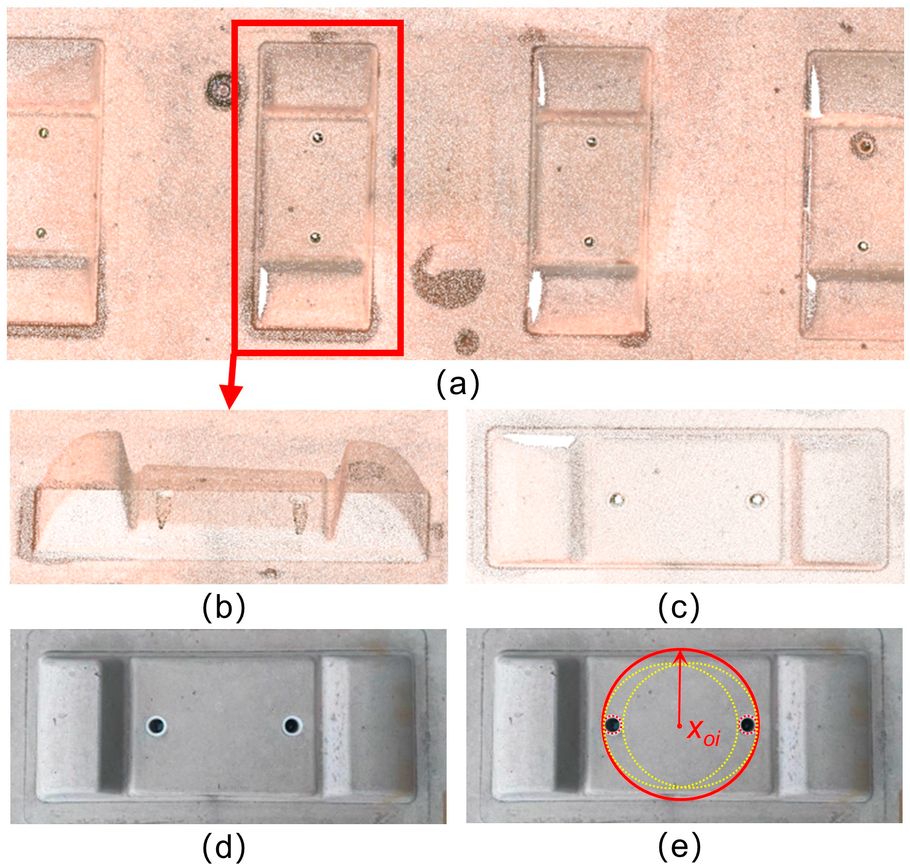
To suppress fitting errors caused by the bearing board inclination, while considering machining tolerances and measurement noise due to field contamination, the board-surface center is computed from the two bolt-hole features as shown in
Figure 3 [
21]. These circles are fitted from texture information, and the center of the minimum enclosing circle of the two fitted circles defines
.
Given that each bearing board is a precision-manufactured component, the top-surface plane can be robustly estimated via PCA, RANSAC, or a least-squares fitting method, yielding
where
denotes the local surface normal.
Under ideal conditions, the rail-top center corresponding to the
i-th bearing board is given by a rigid transform
where
and
representing the rotation and translation from the bearing board frame to the world frame.
Considering the bearing board inclination, a systematic deviation arises between the observed rail-top point
and the theoretical location
The residual for each observation is thus defined as
Accordingly, attitude-induced errors must be compensated during global rail-line fitting to minimize total residuals and suppress systematic bias. Therefore, a nonlinear optimization problem is formulated using the Levenberg–Marquardt scheme, jointly enforcing measurement fidelity, normal consistency, and inter-segment smoothness, while respecting the allowable fastening-adjustment envelope [
22,
23,
24]:
where term (A) denotes the measurement-alignment component, which aligns the virtual long-rail positions to the observed point-cloud data.
is instantiated as the Huber loss to attenuate the influence of gross, sporadic outliers. Term (B) is the normal-consistency component, enforcing alignment between the local surface normal and the design normal
so as to mitigate pose deviations induced by bearing-board tilting. Term (C) is the inter-segment continuity component, enforcing spatial smoothness between adjacent bearing boards.
denotes the fastening-adjustment vector for the
i-th bearing board, ensuring that the computed adjustments remain within the practical, constructible range.
The optimization yields a globally coherent set of virtual rail-top centers , providing a continuous geometric representation of the long-rail alignment and enabling high-confidence spatial pose recovery. By explicitly embedding local attitude compensation under current railway precision-adjustment standards, the proposed model eliminates virtual-physical inconsistency caused by micro-inclinations of bearing boards, significantly enhancing global geometric fidelity. Moreover, the optimized rail geometry directly drives fastening-configuration planning, realizing a digital closed-loop workflow at the execution level, linking measurement, geometric reconstruction, and fastening-configuration planning.
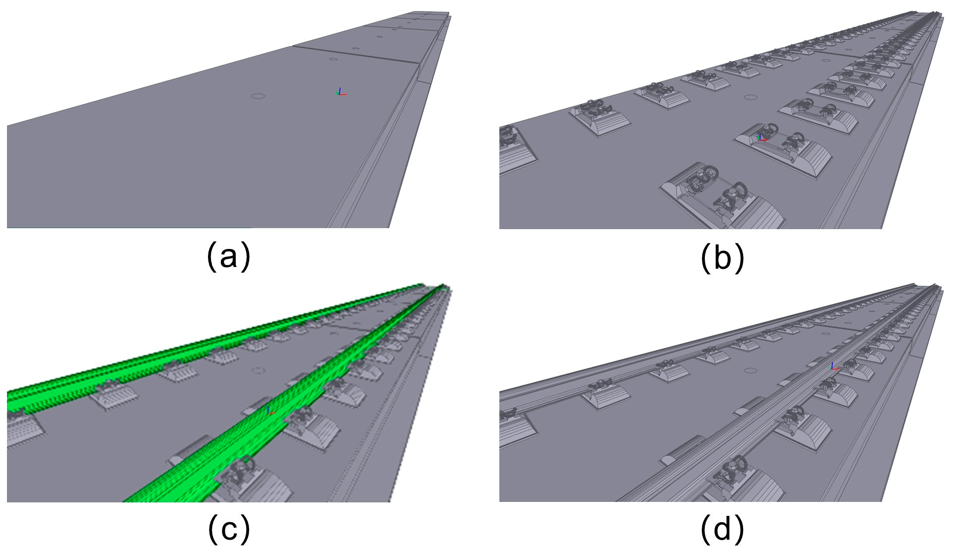
Therefore, the whole virtual pre-adjustment process can be shown in
Figure 4: The initial support configuration based on designed segmentation-based hierarchical modeling drawings (a) is refined using RC-SLAM measurements and standard fasteners (b). Long rail poses are further adjusted with fine adjustment standards and proposed algorithm (c), leading to the optimized final alignment and corresponding non-standard fasteners (d) [
25,
26,
27].
4. Engineering Field Experiments Results and Discussion
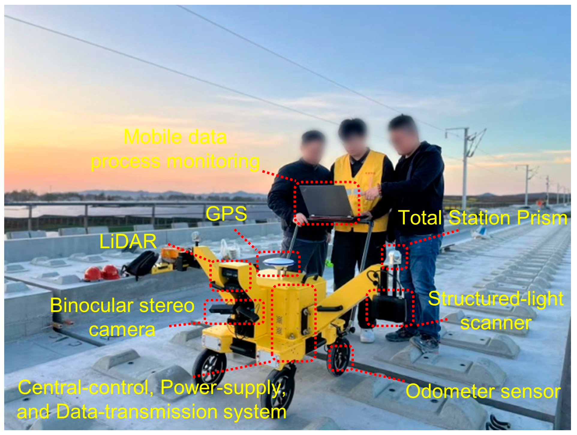
To systematically verify the feasibility, effectiveness, and engineering applicability of the proposed methodology, a prototype
Virtual Pre-adjustment Trolley was developed based on the measurement and modeling approach established in
Section 2 (as shown in
Figure 5). In particular, the prototype trolley integrates the RC-SLAM data-processing pipeline to support consistent long-range reconstruction in railway environments.
The trolley is equipped with the XT32M LiDAR from Hesai Technology and the ZED X camera from Stereolabs, both serving as key components of the RC-SLAM low-frequency framework. They provide large-scale rough mapping data, ensuring the accuracy of track geometry and enabling collision avoidance emergency stop functions. The inertial measurement unit (IMU) used is custom-designed for railways, with an accuracy of 0.2% and combined with an odometer and GPS to provide initial positioning values and motion curves. All sensors are synchronized through a unified hardware time module, with a system latency of less than 5 ms. At both ends of the trolley, two robotic arms are equipped with ZIVID Two structured-light scanners for high-density scanning of the bearing board areas, enhancing the geometric continuity and local detail fidelity required for downstream pose optimization. The trolley itself is 568 mm wide, 947 mm long, and 1023 mm high, providing a compact platform for precise track geometry measurement.
The system is supported by two industrial computers: one featuring a 64 GB NVIDIA Jetson Orin and its associated components, and the other a custom-built industrial computer with an NVIDIA GeForce GTX 1060 graphics card, an Intel i7 processor with HD630 graphics, and CUDA 10.0, responsible for data processing and SLAM computation.
Given that ultra-high-accuracy ground truth data are difficult to obtain in the construction environment and that manual fine adjustment algorithms vary across worksites, a dual-dimension validation strategy is adopted:
Accuracy validation: Compare RC-SLAM measurement results with “total station + prism” manual measurement results to evaluate spatial accuracy and stability.
Engineering comparison: Compare the proposed virtual pre-adjustment approach with the on-site manual fine adjustment approach to assess advantages in accuracy, efficiency, and cost.
4.1. Measurement Accuracy and Stability Validation
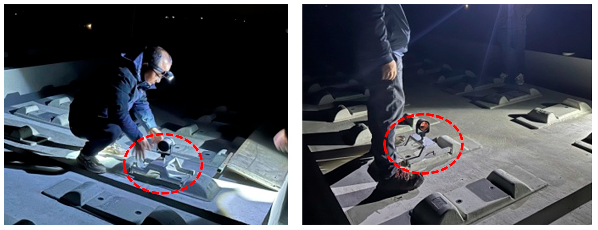
To evaluate the spatial positioning accuracy of the RC-SLAM dual-frame measurement system for the rail-top center, a precision-machined standard prism mount was designed as indicated by the red circle in
Figure 6.
The mount uses a 0.05 mm-precision aluminum alloy base, with a Leica universal prism at the top whose optical center coincides precisely with the ideal rail-top center. The bottom incorporates a compliant adjustment structure that fits directly into the bearing board slot, ensuring consistent and repeatable prism placement.
The experiments were conducted on a 1 km section of ballastless high-speed railway under construction. The experiment section is located in the left-line segment of the Xiangjing Railway, from DK19+818.46 to DK21+127.667, in
Section 4. The design speed is 350 km/h, with a standard track gauge and WJ-8 type fasteners. The section consists of both straight and transition curve segments. Additional experiments were also conducted on the bridge section of the railway.
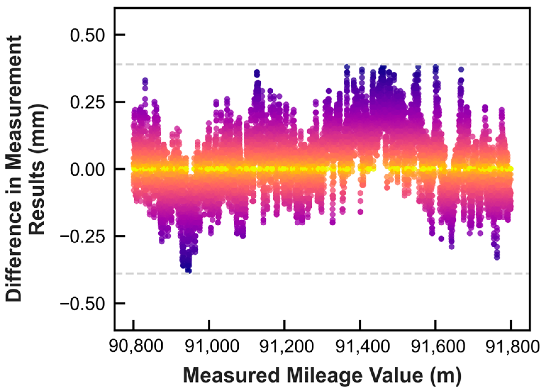
Data acquisition strictly followed the workflow defined in Chapter III, and global coordinate consistency was enforced via CPIII control points at both ends of the section to eliminate systematic offsets. Three repeated experiments were performed along the same alignment, with total station + prism data used as reference for differential analysis. The results can be seen in
Figure 7.
The results show a maximum deviation of 0.39 mm and a repeatability standard deviation of 0.28 mm between the proposed system and manual measurements. The error distribution demonstrates low-variance characteristics with no observable systematic bias. These results confirm that the RC-SLAM dual-frame system achieves sub-millimeter continuous measurement accuracy over long-distance ballastless track, satisfying the 1 mm track adjustment tolerance required in fine alignment tasks. Meanwhile, the achieved accuracy satisfies the geometric tolerance requirements specified in current high-speed ballastless track construction standards.
In terms of operational efficiency, the proposed approach achieves 500 m/h (including control-network registration), compared with 60 m/h for manual measurement, providing an eight-fold improvement and reliable high-fidelity geometric data for virtual pre-adjustment.
4.2. Validation of the Virtual Pre-Adjustment Approach
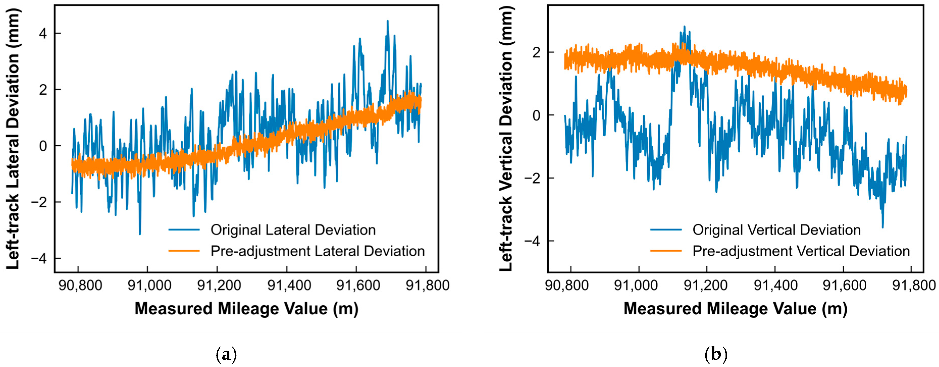
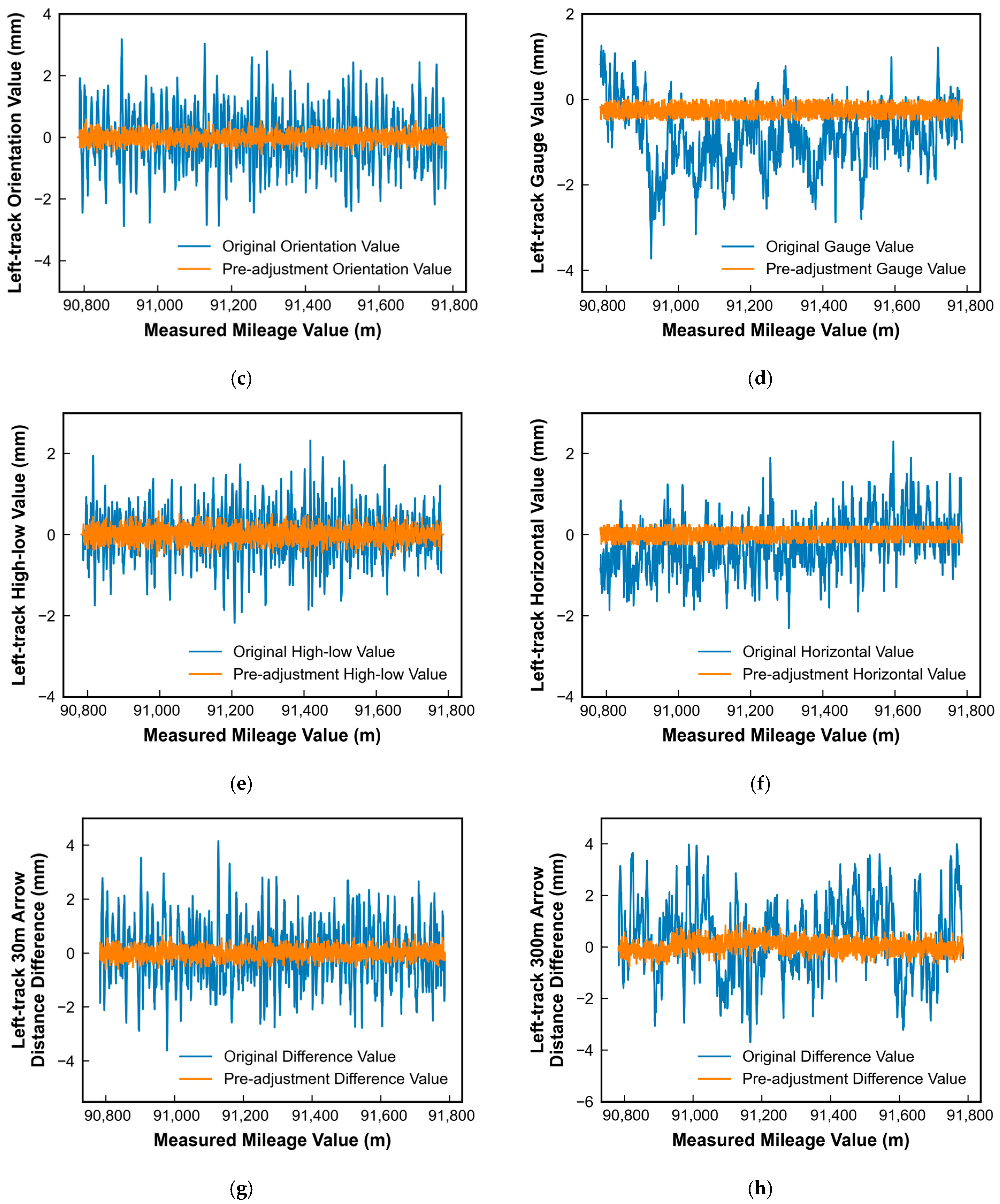
Using the acquired geometric data, a fastening configuration and adjustment solution was generated according to the virtual pre-adjustment pipeline. The effectiveness of the proposed Virtual Pre-adjustment Approach is illustrated in
Figure 8.
As shown in
Figure 8, the comparison between the original and optimized states of the left track demonstrates that the proposed virtual fine-adjustment framework effectively enhances the overall geometric smoothness of the track. After optimization, the deviations of key geometric indicators are substantially reduced. Specifically, for the horizontal alignment, the lateral position is controlled within [−0.5 mm, 0.5 mm], the 30 m arrow-distance difference is constrained to [−1.0 mm, 0.7 mm], the 300 m arrow-distance difference to [−2.7 mm, 2.3 mm], and the gauge variation to [−1.2 mm, 0.5 mm].
Similarly, for the vertical profile, the high–low irregularity is controlled within [−0.7 mm, 1.0 mm], the 30 m arrow-distance difference within [−1.6 mm, 1.4 mm], the 300 m arrow-distance difference within [−4.3 mm, 4.9 mm], and the cross-level within [−1.2 mm, 0.9 mm]. These quantitative results indicate that the optimization primarily suppresses long-wavelength geometric fluctuations while simultaneously improving local continuity, rather than relying on isolated pointwise corrections.
A closer inspection of
Figure 8 reveals that the optimized results exhibit smoother longitudinal continuity and more regular geometric trends along the track. Compared with the original state, the simulated adjustment yields a more coherent spatial alignment that better conforms to practical fastening constraints and construction tolerances. This suggests that the virtual adjustment process does not merely filter measurement noise, but reorganizes the measured geometry into a physically feasible configuration that can be directly implemented in the field.
Based on the simulated fine-adjustment results, the required fastening replacement was statistically analyzed for each adjustment level. For the left track, the proportion of fasteners requiring replacement in the horizontal plane is 78.8%, while the corresponding proportion in the vertical profile is 78.2%. This statistical outcome is consistent with the geometric improvements observed in
Figure 8 and reflects the practical adjustment demand along the test section.
The close correspondence between the simulated adjustment results and the field implementation suggests that the high-precision RC-SLAM-based dual-frame measurements provide a reliable geometric foundation for optimization. The consistency between pre-adjustment simulation and on-site execution confirms that the closed-loop workflow, from accurate measurement to virtual optimization and finally to executable fastening configuration, can effectively support real construction operations.
To evaluate engineering applicability, the virtual adjustment results were compared with the on-site manual fine adjustment scheme, as shown in
Table 1,
Table 2 and
Table 3.
In addition, the final fastener replacement rate, directly indicating economic viability and engineering effectiveness, can be shown in
Table 4.
To further substantiate the effectiveness of the proposed method beyond the geometric comparison in
Figure 8,
Table 1,
Table 2,
Table 3 and
Table 4 provide a quantitative assessment from the perspectives of construction quality, wavelength performance, and practical implementability.
Table 1 indicates that the final Track Quality Index (TQI) obtained by the proposed virtual fine-adjustment (1.13) is essentially equivalent to that achieved through conventional on-site adjustment (1.14). This close correspondence suggests that the simulation-based approach is not merely capable of improving geometric smoothness in a computational sense, but can also deliver adjustment outcomes comparable to established field practice. In other words, the proposed method demonstrates a clear potential to function as a viable alternative to manual fine-adjustment rather than a purely theoretical optimization tool.
Table 2 and
Table 3 examine the peak responses at 30 m and 300 m wavelengths in both planar and elevation domains. The results show that the proposed method consistently suppresses long-wavelength deviations to a level comparable with on-site adjustments while maintaining acceptable short-wavelength behavior. This implies that the method operates within the same engineering tolerance framework as current ballastless track construction practice, rather than introducing an independent or unconventional performance criterion.
Table 4 presents the fastener replacement rates, which serve as a direct indicator of constructability and economic implications. The differences between the virtual adjustment and field results are marginal across all four categories, demonstrating that the simulation not only reproduces similar geometric outcomes but also leads to nearly identical practical adjustment decisions. This consistency is critical for real-world applications, as it indicates that the proposed workflow can be integrated into existing construction processes without fundamentally altering decision-making logic or procurement strategy.
Overall, the combined evidence from
Table 1,
Table 2,
Table 3 and
Table 4 suggests a twofold contribution of the proposed framework: at the outcome level, it can achieve adjustment results equivalent to conventional practice; at the process level, it provides a more systematic and data-driven means of arriving at those results, reducing reliance on iterative field operations and enhancing the predictability of construction planning.
Furthermore, the virtual pre-adjustment approach significantly reduces iterative field adjustments and material replacements. Based on engineering records from the test section, the whole approach can save $2800–$7000 per kilometer of single-track alignment work, while maintaining high-precision control and achieving both economic efficiency and operational feasibility.
5. Conclusions
The geometric condition of ballastless track fundamentally governs the operational quality and long-term service performance of high-speed railways. In current practice, fine adjustment of continuous welded rails still relies heavily on iterative field measurements and experience-based manual corrections, which are constrained by low efficiency, delayed feedback, and non-closed-loop error propagation, leading to substantial labor, time, and material consumption. To address these limitations, this study proposes a simulation-based fine-adjustment framework grounded in high-precision track-geometry sensing and constraint-aware optimization, with the aim of transforming the adjustment workflow from empirical execution to data-driven decision support.
At the methodological level, the proposed approach explicitly formalizes the coupled relationships among track geometry, bearing boards, and fastening behavior, converting traditional experience-driven adjustment into a computable geometric optimization problem. By integrating dual-frame RC-SLAM reconstruction with local structural refinement and spatial attitude compensation, the method achieves kilometer-scale coverage while maintaining sub-millimeter geometric fidelity. A micro-tilt compensation formulation is introduced to mitigate virtual–physical inconsistencies caused by subtle pose perturbations, and the mechanical interaction among rails, bearing boards, and fasteners is parameterized within a constrained nonlinear optimization framework. This formulation enables track regulation to shift from reactive error correction to model-informed adjustment planning under explicit engineering constraints.
Field validation on a 1 km test section demonstrates the practical effectiveness of the proposed framework. As shown in
Figure 8, the optimized geometry significantly suppresses medium- and long-wavelength irregularities in both planar and vertical domains while preserving local continuity. Quantitatively, the final Track Quality Index (TQI = 1.13) is essentially equivalent to that achieved through conventional on-site adjustment (TQI = 1.14), indicating that the virtual approach can deliver outcomes comparable to established field practice. Moreover, the fastener replacement rates derived from the simulation are nearly identical to those from manual adjustment, confirming that the method produces not only similar geometric results but also consistent engineering decisions. This demonstrates that the virtual adjustment process aligns with real construction logic rather than imposing purely mathematical optimization.
From an efficiency and cost perspective, the proposed workflow shifts a substantial portion of adjustment effort from site operations to pre-construction simulation, thereby reducing repeated field interventions and improving planning predictability. Project-based field estimation indicates a direct cost reduction of approximately $2800–$7000 per kilometer per single track by decreasing iterative adjustments and unnecessary component replacement. Equally important, the RC-SLAM measurement subsystem demonstrated stable performance in real construction environments, providing a stable and reliable geometric foundation for large-scale, high-accuracy 3D mapping.
Overall, this work elevates continuous welded rail fine adjustment from an empirical field procedure to a measurement- and simulation-supported geometric process. By establishing a closed-loop workflow encompassing sensing, modeling, simulation, adjustment, and verification, the proposed approach enhances consistency, efficiency, and traceability in track geometry control without exceeding practical construction capabilities. While the present study focuses on construction-stage application, the high-fidelity geometric data and closed-loop optimization framework provide a reliable foundation for future digital twin developments in railway infrastructure.
Future research will explore predictive construction support, tighter integration with asset management systems, and extension of the method to bridges, tunnels, and other linear railway structures, subject to problem-specific modeling and validation.