1. Introduction
Robotic manipulation depends on the capacity of an end-effector to establish stable physical contact with objects and transmit the forces required for grasping, positioning, and assembly. Conventional rigid grippers offer high precision and repeatability in structured environments; however, their performance generally depends on prior knowledge of the geometry, orientation, and mechanical properties of the manipulated object. These requirements limit their adaptability when handling fragile, deformable, or irregularly shaped objects [
1,
2,
3].
Soft robotic end-effectors have emerged as an alternative because their compliant structures can passively conform to different surfaces and distribute contact forces over a larger area. Their mechanical adaptability reduces the need for highly accurate object models and decreases the possibility of damaging delicate products. Soft grippers have consequently been proposed for industrial manipulation, agriculture, healthcare, and human–robot interaction [
4]. Depending on the application, these devices may employ pneumatic actuation, tendons, cables, controlled stiffness, adhesion, or hybrid mechanisms to generate the required grasping motion.
Despite these advantages, structural compliance introduces an important sensing and control problem. Unlike rigid mechanisms, the deformation of a soft finger cannot always be inferred directly from the displacement of its actuator. Its configuration depends on the geometry, position, stiffness, and weight of the object, as well as on the contact conditions established during grasping. Therefore, actuator position alone may not indicate whether contact has occurred, whether the object is securely held, or how the load is distributed throughout the flexible structure. Developing soft end-effectors capable of simultaneously perceiving and grasping is thus essential for achieving reliable manipulation of delicate and difficult-to-handle objects [
5,
6].
Force-sensing resistors and other conventional sensors can be attached to the contact surfaces of a gripper to obtain information about the interaction with an object [
7]. However, this approach commonly requires additional wiring, adhesives, supporting structures, and assembly operations. These elements increase manufacturing complexity and may create rigid interfaces that interfere with the natural deformation of the soft body. Flexible and stretchable sensors offer greater mechanical compatibility, but their integration, protection, electrical connection, and operational durability remain relevant challenges [
8,
9]. Incorporating the sensing element directly into the end-effector during fabrication could reduce these limitations and simplify the resulting robotic system.
Additive manufacturing provides considerable freedom for producing compliant structures with complex and application-specific geometries. Among the available processes, fused deposition modeling (FDM) is particularly attractive because of its accessibility, low cost, and capacity to manufacture functional components directly from three-dimensional models [
10,
11]. FDM also facilitates rapid design iterations and low-volume production, allowing the geometry of an end-effector to be adapted to a particular manipulation task without requiring molds or specialized tooling. The layer-by-layer deposition process has consequently supported the transition of three-dimensional printing from a prototyping technique to a manufacturing alternative for functional robotic components.
Flexible thermoplastics such as thermoplastic polyurethane (TPU) are especially relevant to soft robotics because of their flexibility, tensile strength, abrasion resistance, and capacity to recover after deformation [
12]. Nevertheless, FDM components exhibit anisotropic behavior caused by the orientation and adhesion of the deposited layers. Printing direction, layer height, extrusion temperature, infill configuration, material humidity, and deposition parameters can influence stiffness, tensile resistance, deformation, fatigue, and interlayer failure [
13,
14,
15,
16,
17]. These effects become particularly important when the manufactured component is subjected to thousands of repeated grasping cycles.
Multimaterial additive manufacturing extends the capabilities of FDM by allowing conductive and non-conductive polymers to be deposited within the same component. Conductive filaments containing carbon-based particles can form electrically responsive paths whose resistance changes when subjected to elongation, compression, or bending [
18,
19,
20]. These paths can therefore function as deformation-sensitive elements embedded directly within the compliant structure. Compared with externally mounted sensors, this approach may reduce the number of components, simplify assembly, and produce a more compact sensorized end-effector.
Previous research has demonstrated several strategies for integrating sensing elements into additively manufactured components. Sensors can be inserted by interrupting the printing process, embedded as conductive islands within an insulating structure, or completely manufactured through coordinated multimaterial deposition [
21,
22]. Conductive PLA and TPU have also been combined to produce capacitive or deformation-sensitive devices [
23]. These studies confirm the feasibility of manufacturing functional sensing elements as part of the printed component rather than attaching them after fabrication.
However, combining TPU and conductive PLA introduces important mechanical and manufacturing difficulties. The substantial difference between the stiffness and deformation capacity of both materials can generate stress concentrations at their interface. Adhesion between PLA and TPU is also influenced by surface roughness, deposition conditions, and the geometry of the contact region [
24]. During repeated operation, these effects may produce delamination, conductive-path fracture, hysteresis, drift, or loss of electrical continuity even when the surrounding TPU structure remains mechanically functional. Consequently, an initial resistance change does not by itself demonstrate that the sensing element can remain operational throughout the useful life of the gripper.
Existing studies have separately addressed soft and adaptive grippers, flexible sensors, embedded electronic components, conductive polymer structures, additive manufacturing, interfacial adhesion, and compliant robotic mechanisms [
5,
7,
8,
19,
21,
22,
23]. Collectively, these investigations demonstrate the feasibility of manufacturing compliant robotic components incorporating embedded conductive elements. Nevertheless, their emphasis is commonly placed on the development of a particular gripper, the initial characterization of a sensing material, the feasibility of embedding a conductive element, or the functional performance of a specific structure. Limited attention has been given to the comparative evaluation of different embedded lattice geometries under prolonged repetitive robotic operation.
Therefore, limited comparative evidence is available regarding how embedded lattice geometry influences grasping performance, structural integrity, and durability under repeated robotic operation. In particular, few studies have compared different embedded lattice geometries through prolonged pick-and-place tests while also examining their capacity to maintain a detectable electrical response during cyclic deformation. Consequently, it remains unclear which geometry provides the most favorable functional durability for repetitive robotic manipulation. This constitutes the research gap addressed in the present study.
Although stiffness, deformation, stress concentration, and fatigue behavior are relevant mechanical mechanisms in lattice structures [
25,
26], the objective of this study is to design, manufacture, and experimentally evaluate a soft robotic end-effector by comparing four embedded lattice geometries—diamond, square, hexagonal, and triangular—through robotic pick-and-place experiments and cyclic durability tests. The electrical response of the embedded conductive paths was additionally monitored to verify their potential use as deformation-sensitive elements.
The novelty of the study lies in the experimental comparison of four embedded lattice geometries under prolonged robotic operation. Rather than evaluating the geometries only through isolated deformation tests, the proposed approach examines their grasping performance, visible structural damage, and accumulated operating cycles during repetitive pick-and-place tasks. The conductive response is included as a complementary functional assessment of the embedded paths. This approach provides experimental evidence for selecting embedded lattice geometries for soft robotic end-effectors intended for the repetitive manipulation of delicate or irregularly shaped objects.
2. Materials and Methods
2.1. Mechanical Design of the End-Effector with Embedded Lattices
The proposed end-effector was designed as a parallel two-element gripper combining a rigid transmission structure with compliant gripping elements incorporating embedded lattices. The complete assembly was parametrically modeled in SolidWorks 2024 to facilitate dimensional adjustments, mechanical integration, and fabrication through fused deposition modeling (FDM). Its modular configuration allowed each gripping element to be independently removed and replaced, enabling the evaluation of four lattice geometries using the same actuation and mounting system. The structural components were joined with screws, while the compliant gripping elements were attached to the transmission mechanism using M6 bolts.
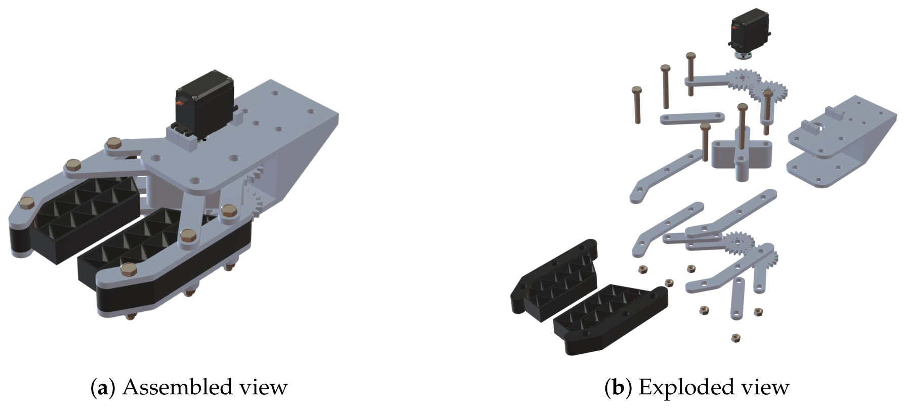
Figure 1 presents the assembled and exploded views of the proposed end-effector, showing the arrangement of its mechanical components and their integration within the gripping system. The complete CAD models of the four lattice geometries, including their external dimensions, cell dimensions, member thicknesses, attachment points, and conductive-path configurations, are provided as
Supplementary Materials.
The opening and closing motion was generated by an M996R servomotor (TowerPro) with an angular range of 180°. The servomotor moved between programmed angular positions of 40° and 130°, corresponding to an angular displacement of 90°. The actuator drove two symmetrical four-bar mechanisms through two pairs of gears with a 1:1 transmission ratio. This arrangement produced simultaneous motion in opposite directions, generating a parallel grasping action. The rigid structure supported the actuator and transmission components, whereas the compliant elements adapted to the geometry of the manipulated objects.
The compliant gripping elements were fabricated from thermoplastic polyurethane with a Shore hardness of 95A (TPU 95A). Each element incorporated an internal lattice manufactured from Protopasta conductive PLA and embedded within the TPU structure during fabrication. The embedded lattice contributed to the structural behavior of the gripping element and varied its electrical resistance when deformed.
Four lattice geometries were developed: diamond, square, hexagonal, and triangular, as shown in
Table 1. The external dimensions and attachment points were maintained constant, while only the internal geometry and conductive route were modified. This configuration allowed all geometries to be installed in the same mechanical assembly, reducing the influence of the actuator, transmission mechanism, and mounting conditions on their comparison.
For the pick-and-place durability tests, three objects were selected to represent different grasping challenges. The relay was chosen because of its weight and regular prismatic geometry, representative of components commonly manipulated by robotic end-effectors. The wheel was selected because its circular profile required the lattice to conform to a curved surface during grasping. Finally, the egg was included as a fragile object to evaluate whether the compliant structure could adapt to its curved surface and manipulate it without causing damage. Three independent TPU lattice specimens were manufactured for each geometry, with one specimen assigned to each object. Therefore, no specimen was reused across different object tests.
Table 2 shows the object dimensions. The same end-effector and actuation mechanism were maintained throughout the experiments.
The conductive route extended through the deformable region and terminated at electrical connection points near the fixed end of each gripping element. Preliminary designs considered multiple conductive paths arranged as a sensing matrix; however, the final configuration used one continuous route because the matrix did not maintain adequate electrical continuity during operation. Consequently, the end-effector incorporated two independent conductive channels, one for each compliant gripping element.
Table 3 shows FDM main parameters, material-specific extrusion parameters, including printing temperatures and speeds, were established according to the recommended processing conditions provided by the TPU 95A and conductive PLA manufacturers.
2.2. Pick-and-Place Durability Test
A functional durability test was conducted by mounting the end-effector on a SCARA robot programmed to perform repeated pick-and-place operations using an egg, a wheel, and a relay as manipulated objects. These objects were selected to evaluate the capacity of the compliant fingers to grasp and transport objects with different geometries and characteristics.
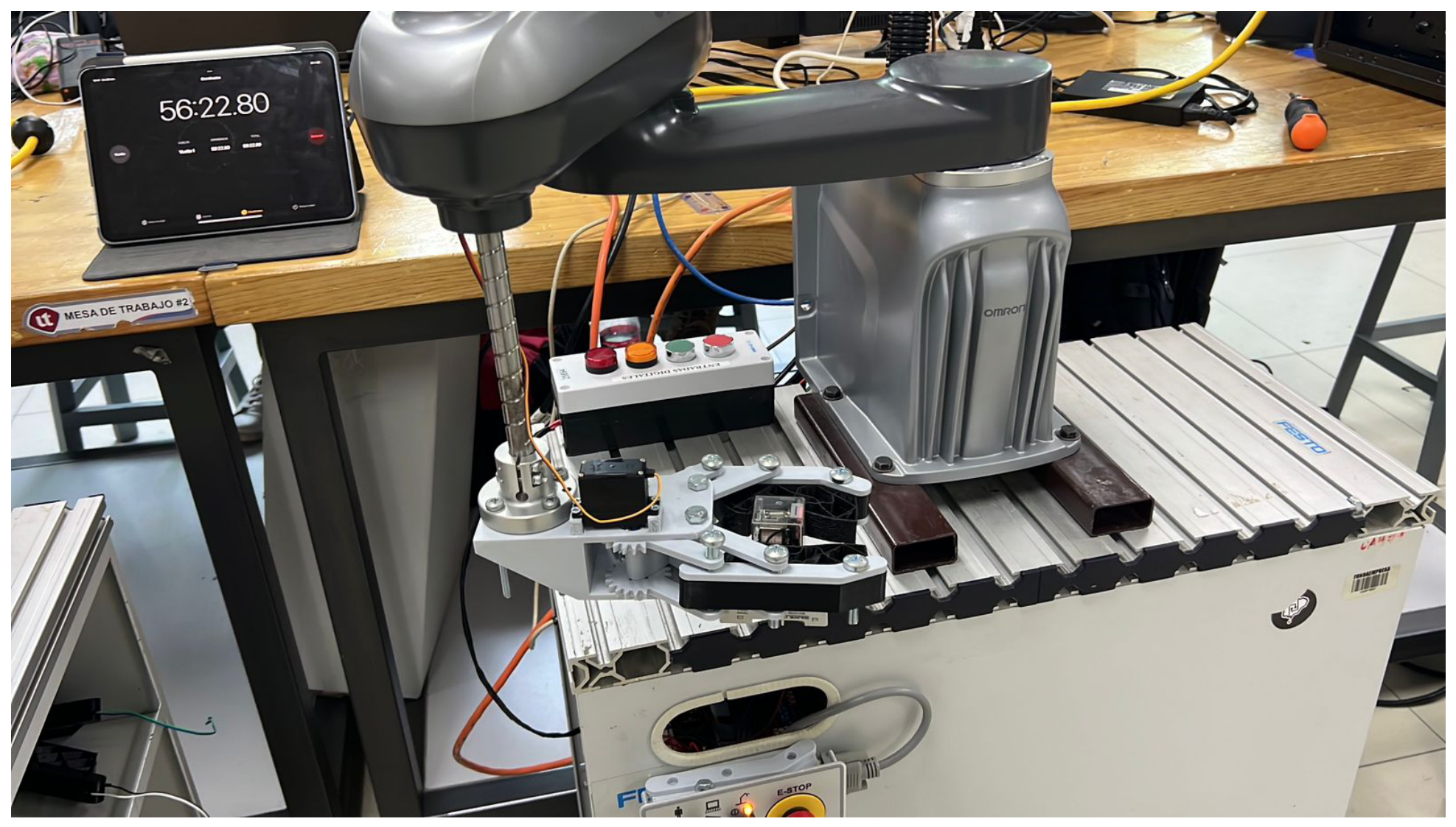
Figure 2 shows the experimental setup used for the cyclic pick-and-place tests. The proposed end-effector was mounted on the SCARA robot, while the control system executed the programmed manipulation sequence and the elapsed test time was monitored externally.
Each cycle comprised the following sequence: the robot moved to the pick-up position, lowered the end-effector toward the object, closed the fingers, lifted and transferred the object to the placement position, released it, and returned to its initial configuration. The same programmed trajectory and gripper commands were maintained throughout each test.
A cycle was considered successfully completed when the object was grasped, transported, and released at the intended position without falling or being damaged. The test also examined whether the fingers recovered their initial geometry after releasing the object. Testing of a lattice geometry was discontinued when visible structural damage, permanent deformation, or loss of grasping functionality prevented the gripping element from continuing under the established operating conditions. Consequently, the lattice geometries completed different numbers of cycles because their experimental exposure depended on their capacity to continue operating without functional or structural failure. The accumulated operating time and completed repetitions were recorded for each geometry.
Object dropping, visible structural damage, and permanent deformation were recorded as functional failures. The experiment was conducted independently of the electrical characterization and was used to assess the functional durability and practical grasping capability of the end-effector during repeated robotic manipulation.
2.3. Complementary Conductive Response Test
A separate experiment was conducted to verify whether the embedded conductive PLA paths produced a detectable electrical response during deformation. The purpose of the test was to confirm the potential of the embedded paths to function as deformation-sensitive elements rather than to perform a complete electrical characterization. The same acquisition procedure was applied to the diamond, square, hexagonal, and triangular lattice geometries. The compliant gripping elements were fabricated in a single printing process using a Sovol SV04 printer (Sovol) equipped with an Independent Dual Extruder (IDEX) system. One extruder deposited TPU 95A to manufacture the compliant body, while the second extruder deposited Protopasta conductive PLA to form the internal conductive lattice. Automatic tool changes were programmed in Prusaslicer 2.7.3, allowing the conductive path to be embedded directly within the TPU structure without a subsequent assembly step.
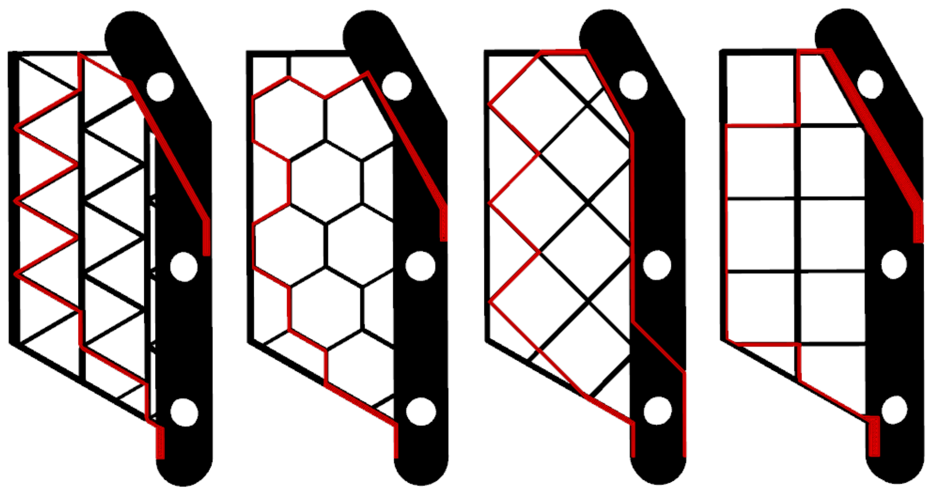
Figure 3 shows the proposed routes for the triangular, hexagonal, diamond, and square lattices used in the experimental tests. The routes were adapted to the internal geometry of each lattice while maintaining continuous electrical connectivity between their terminal points.
The electronic system was based on an ATmega328P microcontroller and comprised power regulation, signal conditioning, data acquisition, actuator control, and data-storage stages. The microcontroller acquired the analog signals generated by the two conductive lattices, controlled the servomotor through a pulse-width-modulated signal, and received a Boolean opening or closing command from the robotic controller. The acquired signals were stored for subsequent analysis and were not used to implement active force control.
Each conductive lattice was incorporated into a voltage-divider circuit. The voltage associated with its electrical resistance was determined as:
where
is the supply voltage,
is the fixed reference resistance, and
is the variable resistance of the conductive lattice. Therefore, deformation-induced changes in
produced corresponding variations in
.
The resulting signal was conditioned using an LM324AN operational amplifier (STMicroelectronics). Each sensing channel incorporated an independently adjustable trimmer potentiometer to accommodate differences in the electrical resistance of the printed lattices. The conditioned signals were sampled through two analog inputs of the ATmega328P (Microchip Technology). Its 10-bit analog-to-digital converter represented the 0–5 V input range using values from 0 to 1023, according to:
where
D is the acquired digital value and
V is the reference voltage of the analog-to-digital converter.
An LM7805 voltage regulator converted the external supply, specified between 7 and 35 V, into the regulated 5 V required by the microcontroller and associated electronics. An LED connected to the regulated output indicated the operating status of the power stage. The acquired data were stored on a 32 GB SD card through an SPI interface and subsequently processed in MATLAB R2024a (MathWorks).
The electronic schematic and printed circuit board layouts were developed using Proteus 8.9, and the manufacturing files were converted into CNC toolpaths using FlatCAM 8.5. Two single-sided printed circuit boards were used to separate the processing and signal-conditioning stages.
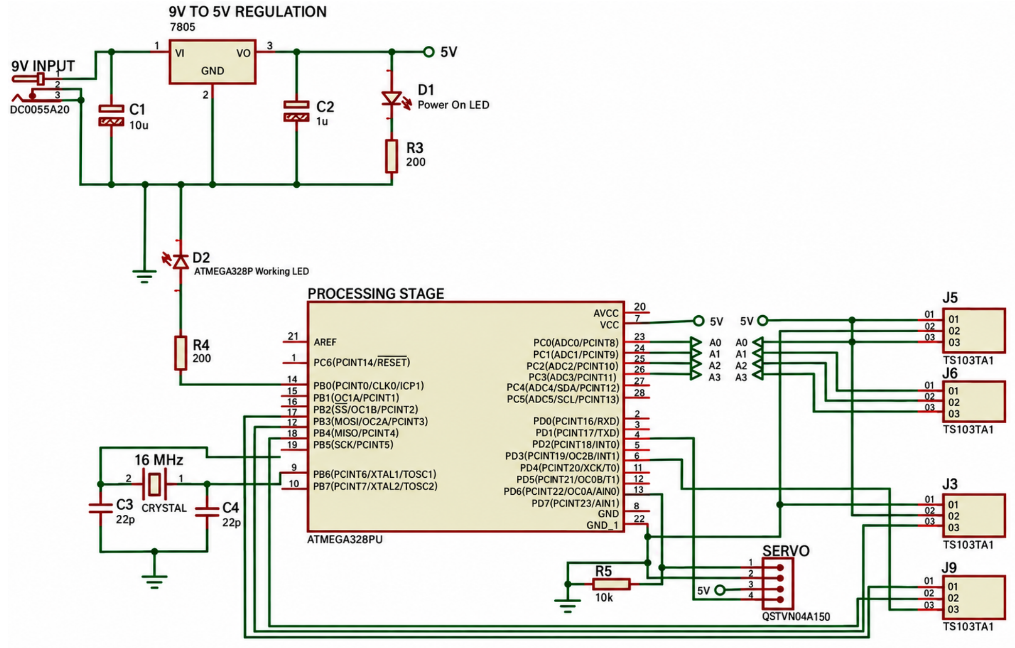
Figure 4 shows the signal-conditioning circuit developed for the two conductive lattices. A 1.5 V reference voltage was generated using a resistive voltage divider, while two LM324AN operational-amplifier (STMicroelectronics) channels conditioned the signals independently. An adjustable trimmer potentiometer in each channel allowed the circuit to accommodate differences in the baseline resistance and electrical response of the printed lattices before the conditioned signals were acquired by the microcontroller.
For the conductive response test, each gripping element was initially maintained in its undeformed condition, and the corresponding digital output was recorded as the reference value. The element was then deformed to reproduce the bending associated with contact during grasping, while the response of the conductive lattice was acquired. The change relative to the initial condition was calculated as:
where
is the digital value recorded in the undeformed condition and
D is the value measured after deformation. A variation in
indicated that deformation of the conductive lattice generated a detectable electrical response. The conductive signal was recorded during a new test of pick-and-place cycles and was not used to determine the functional durability of the gripping elements.
4. Discussion
The novelty of this study lies in the functional evaluation of different lattice geometries during prolonged robotic pick-and-place operation. Each geometry–object condition was analyzed separately. The relay provided a common condition for the four TPU geometries, the wheel enabled comparison between the hexagonal and diamond configurations, and the egg assessed adaptation to a fragile object.
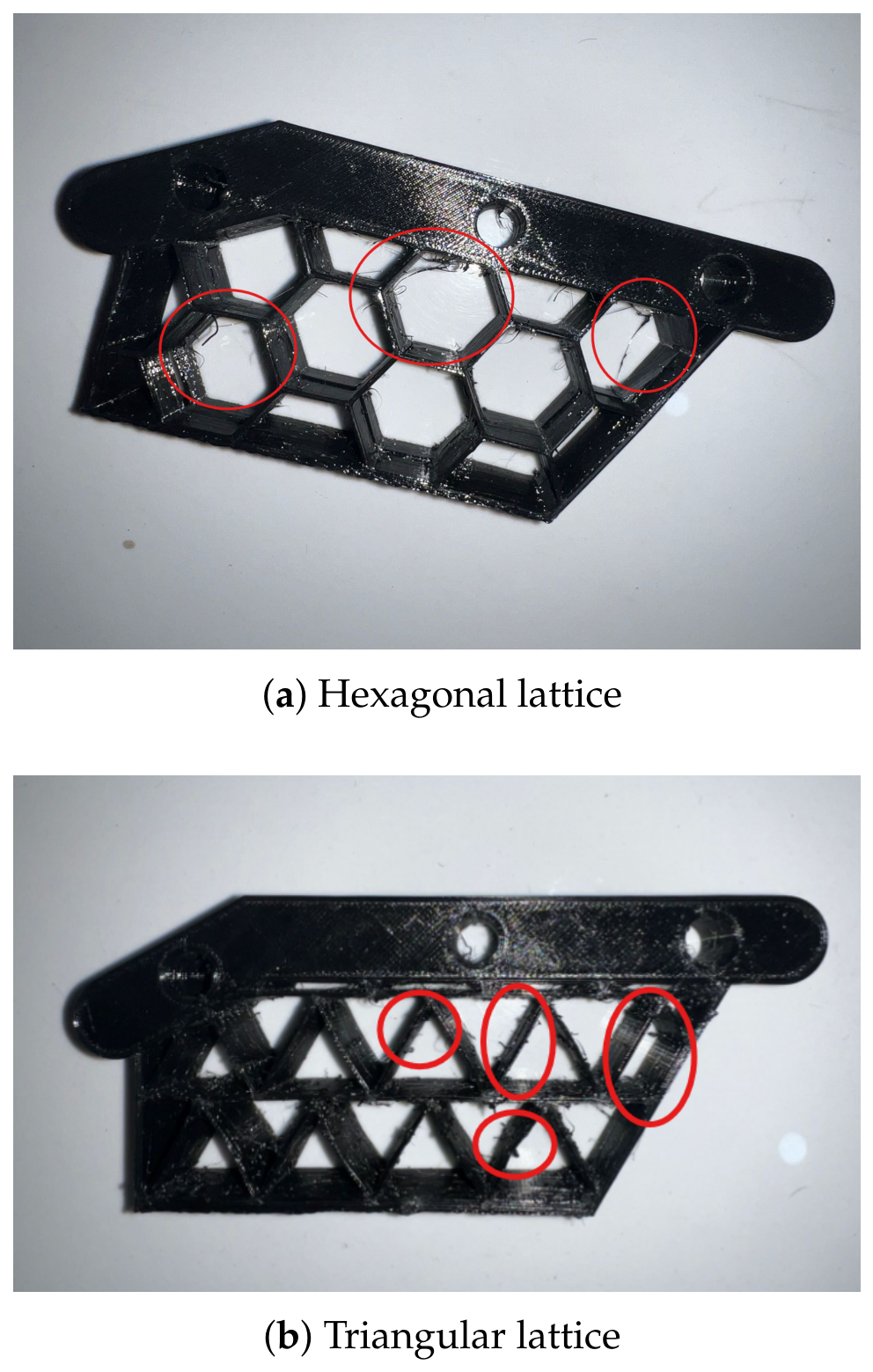
The hexagonal geometry completed the greatest number of repetitions with both the relay and wheel, although localized cracking appeared at some cell junctions. The diamond lattice showed no visible fracture but eventually lost sufficient grasping capability to retain the object. The triangular geometry exhibited fractures in its diagonal members, whereas the square geometry presented permanent deformation. During the egg test, the square and diamond specimens completed 1350 and 1800 repetitions, respectively, without damaging the object, demonstrating their functional adaptability rather than fatigue resistance.
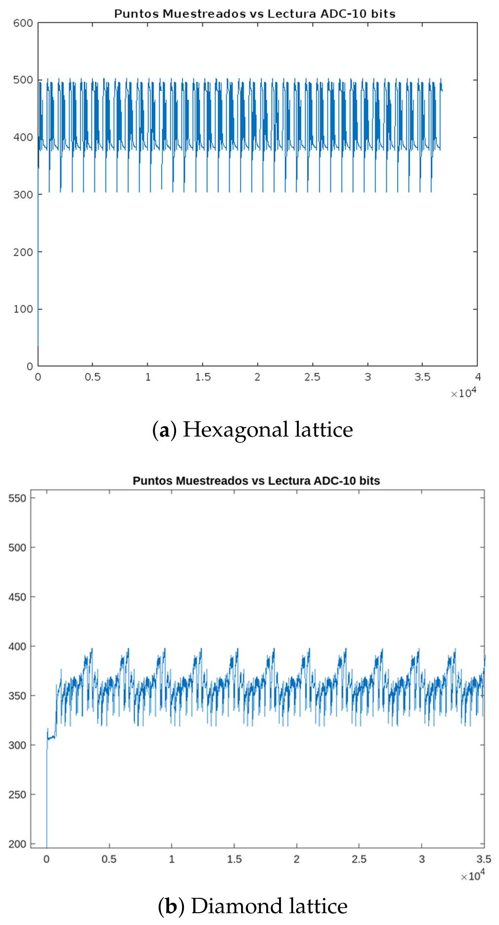
In the separate conductive-response evaluation, the diamond and hexagonal configurations manipulated the same relay. The diamond maintained a detectable periodic ADC response for approximately 9969 cycles, compared with approximately 4984 cycles for the hexagonal configuration. These results demonstrate prolonged electrical responsiveness but not differences in electrical sensitivity. The replaceable lattice elements were evaluated using the same actuation and transmission system, providing practical evidence for selecting configurations according to specific requirements rather than identifying a universally superior geometry.
4.1. Contribution to the Identified Research Gap
Lattice structures have previously been incorporated into pneumatic soft actuators to modify their stiffness, deformation, generated force, and conformity. Bio-inspired lattice chambers, including honeycomb and other cellular configurations, have demonstrated that internal geometry can regulate actuator behavior under controlled pneumatic pressure [
27,
28]. However, these systems require pneumatic pressure-generation and distribution components, and their evaluations have primarily focused on deformation and force rather than prolonged robotic pick-and-place operation.
Cable- or tendon-driven architectures provide an alternative for actuating compliant lattice fingers. Cellular, functionally graded, and monolithically printed fingers have demonstrated adaptable grasping and controllable deformation [
29,
30,
31]. Although these approaches avoid pneumatic chambers, their operation depends on tendon routing and tension transmission. Some tendon-driven structures have demonstrated endurance over thousands of actuation cycles [
30,
31].
Long-term cyclic evaluations have also been conducted on individual TPU pneumatic actuators and conductive TPU specimens. These studies include pneumatic actuators tested until mechanical failure and conductive structures subjected to several thousand standardized deformation cycles [
32,
33]. Nevertheless, these experiments generally characterize isolated actuators or material specimens rather than replaceable lattice elements during prolonged robotic manipulation.
Accordingly, the contribution of the present study is not the first use of lattice structures, TPU, or cyclic testing in soft robotics. Its contribution lies in the functional comparison of four replaceable lattice geometries within the same servo-driven end-effector, their evaluation during repeated robotic pick-and-place operation, and the complementary monitoring of embedded conductive PLA paths. Unlike pneumatic and tendon-driven alternatives, the proposed mechanism uses a servomotor and parallel transmission without a pneumatic supply or tendon routing. The results therefore provide operational evidence regarding functional endurance and different failure modes, although replicated mechanical characterization remains necessary for statistically validated comparisons.
4.2. Limitations
Only one independently manufactured specimen was evaluated for each geometry–object combination. Consequently, specimen-to-specimen variability, printing variability, and material or interface defects could not be quantified, and dispersion measures, confidence intervals, and inferential statistical analyses could not be calculated.
The exact cycle at which cracking, permanent deformation, or progressive loss of grasping capability began was not recorded. Damage was assessed through visual inspection without dimensional, microscopic, or internal analysis, and no quantitative thresholds were established for visible structural damage or permanent deformation. Therefore, the reported repetitions represent functional endurance under the evaluated pick-and-place conditions and should not be interpreted as a formal fatigue-life characterization.
The objects imposed different grasping conditions because of their geometry, contact location, and required conformity. For this reason, cycle counts were interpreted separately for each object and were not combined to compare the geometries. Experimental force–displacement curves, effective stiffness, grasping force, strain, and energy absorption were also not measured; therefore, the mechanical mechanisms responsible for the observed differences could not be quantitatively determined. Gripping force, contact force, servo torque, and lattice deformation were not directly measured; consequently, the mechanical loading experienced by each lattice could not be quantitatively determined.
The conductive-response experiment was performed using newly manufactured specimens incorporating embedded conductive PLA and was therefore not mechanically equivalent to the initial TPU evaluation. Sensitivity, hysteresis, linearity, drift, electrical resistance, and repeatability under standardized force or displacement conditions could not be determined from the available ADC signals. Furthermore, the signal-conditioning channels were adjusted independently. Consequently, the recorded signals demonstrate detectable electrical responsiveness but do not constitute a complete characterization or direct comparison of sensing performance.
Finally, changing the lattice geometry simultaneously modified the conductive-path length, orientation, number of junctions, and electrical resistance. The individual mechanical and electrical effects of these characteristics could therefore not be isolated. Additional controlled experiments using multiple independently manufactured specimens and standardized loading conditions are required to quantify the mechanical and electrical properties of the embedded lattice configurations.
5. Conclusions
The results showed that the embedded lattice geometries exhibited different functional behaviors during repeated robotic pick-and-place operation. In the common relay test, the triangular, square, diamond, and hexagonal specimens completed 1200, 1500, 2400, and 2550 repetitions, respectively. The triangular specimen exhibited localized fractures and partial separation of diagonal members, while the square specimen showed permanent deformation and localized structural damage. The diamond specimen did not exhibit visible fractures but eventually lost sufficient grasping capability to retain the relay. The hexagonal specimen completed the greatest number of repetitions under this common testing condition, although localized cracking and separation were observed at some cell junctions.
During the wheel test, the diamond and hexagonal specimens completed 1500 and 1800 repetitions, respectively, confirming the greater functional endurance of the hexagonal geometry under this condition. In the separate egg test, the square and diamond specimens completed 1350 and 1800 repetitions, respectively, without damaging the fragile object. This result demonstrated the ability of both compliant configurations to adapt to a curved and fragile surface.
The prolonged conductive-response evaluation was restricted to the diamond and hexagonal geometries using the relay as the common manipulated object. The diamond configuration completed approximately 9969 pick-and-place cycles over 72 h, whereas the hexagonal configuration completed approximately 4984 cycles over 36 h. Both configurations maintained detectable periodic ADC responses during robotic operation. Because the signal-conditioning channels were adjusted independently, these results demonstrate prolonged electrical responsiveness but do not constitute a direct comparison of electrical sensitivity.
Overall, the hexagonal geometry exhibited the greatest functional endurance during the initial TPU pick-and-place tests, whereas the diamond geometry provided the most favorable overall balance between adaptability to different objects and prolonged electrical responsiveness. These findings should be interpreted as descriptive experimental observations because only one specimen was evaluated for each geometry–object combination. Therefore, the results do not establish statistically validated differences in fatigue life or demonstrate the universal superiority of any lattice geometry.




 ,
,