Article

Panel Interaction and Incremental Subsidence in Multi-Panel Longwall Mining: Mechanisms and Mitigation of Ground Instability


1
School of Mines, China University of Mining and Technology, Xuzhou 221116, China
2
School of Minerals and Energy Resources Engineering, University of New South Wales, Sydney, NSW 2052, Australia
*
Author to whom correspondence should be addressed.
Appl. Sci. 2026, 16(18), 9052; https://doi.org/10.3390/app16189052 (registering DOI)
Submission received: 17 August 2026 / Revised: 6 September 2026 / Accepted: 9 September 2026 / Published: 12 September 2026

Abstract

Incremental subsidence induced by sequential longwall panel extraction is associated with panel interaction and progressive instability of the disturbed rock mass. However, the governing mechanisms and the coupled effects of panel and pillar geometries remain insufficiently understood, limiting effective assessment and mitigation of cumulative ground deformation in longwall mining. This paper investigates the mechanisms and influencing factors of incremental subsidence through comprehensive approaches including field data interpretation, numerical modelling, parametric study, and sensitivity assessment. A numerical model is developed to simulate the stress and deformation response of the overburden and inter-panel pillars to sequential panel extraction under representative geological and in-situ stress conditions. The results indicate that incremental subsidence is primarily governed by stress redistribution, lateral compaction, and distance-dependent attenuation. Extraction of a subsequent panel induces secondary loading and compaction within the previously mined panel domain, thereby enhancing horizontal displacement and surface settlement, while the influence of further mining diminishes with increasing pillar width due to stress relief and reduced overburden stiffness. Parametric sensitivity assessment reveals a coupled dependence of incremental subsidence on panel and pillar widths: narrow pillars of 15 m produce up to 3 to 4 times greater incremental subsidence above the first panel compared with wide pillars of 75 m, while wider panels amplify the sensitivity of subsidence to pillar width. These findings reveal the progressive evolution of mining-induced rock mass deformation and provide quantitative guidance for optimising panel and pillar configurations to reduce cumulative subsidence and ground-instability risks.

1. Introduction

The longwall mining method has been widely adopted for underground coal resource recovery because of its high efficiency and productivity. However, large-scale extraction inevitably induces extensive ground movement and surface subsidence, which may threaten surface infrastructure, groundwater systems, and eco-environmental sustainability [1,2,3,4,5]. Accurate prediction and effective control of mining-induced subsidence are therefore essential for mitigating mining-induced ground instability and remain critical challenges in modern underground mining.
The characteristics of subsidence induced by single-panel extraction have been extensively investigated. For an isolated longwall panel, the surface subsidence trough typically exhibits symmetric features in geometry, magnitude, and spatial extent [6,7,8], with the maximum vertical displacement occurring above the panel centreline under idealised symmetric conditions [9,10,11]. When the panel width-to-depth ratio remains below the subcritical threshold, the trough is broad and smoothly curved, whereas under supercritical conditions it may develop a relatively flat bottom as maximum subsidence is approached [11]. The lateral extent of surface deformation is often defined by the angle of draw, which typically ranges from about 8° to 45° from the vertical and delineates the outer boundary of mining impact [2,3,12]. In terms of magnitude, subsidence induced by the first panel is often limited in deep mining, accounting for only about 10% to 15% of the final potential subsidence [13]. This stage is referred to as the super-subcritical stage, during which the Primary Key Stratum (PKS), representing the thickest and stiffest overburden layer, remains elastically stable and unfractured [13,14,15]. In contrast, in high-intensity shallow mining (with cover depths smaller than 200 m), the subsidence ratio may significantly increase, reaching 51.1% to 54.3% of the mining height [11].
In multi-panel and multi-seam mining, ground deformation becomes more complex as successive panel extractions interact with an overburden that has already been disturbed, fractured, and partially compacted. The resulting additional ground movement is commonly referred to as incremental subsidence, distinguishing the deformation induced by subsequent panel extraction from that associated with a single panel [2,16]. Incremental subsidence can be substantially greater than the deformation associated with isolated-panel extraction, with the ratio of maximum subsidence to mining height exceeding that observed in single-panel extraction and, in extreme cases, surpassing the thickness of the newly extracted panel [17,18,19]. This behaviour is attributed to progressive weakening and loss of bearing capacity of key strata [10,16,20]. In addition, the spatial pattern of displacements is also modified: the location of maximum subsidence frequently shifts toward overlapping panel regions or the margins of previously formed goafs, producing irregular trough profiles with localised maxima rather than a single symmetric deflection [10,11,16]. Moreover, the impacted surface area and angle of draw become dependent on panel configuration, and the subsidence response tends to be asymmetric and more rapid when extraction occurs beneath an existing goaf [21,22]. These observations indicate that incremental subsidence is not simply the superposition of individual panel responses, but reflects the mechanical interaction between successive mining domains.
The intensity and spatial extent of such panel interaction are governed by several interrelated factors, including rock property modification, mining geometry, and pillar stability [2,23,24]. Historical mining activities reduce the strength and bridging capacity of key strata, promote void closure and goaf compaction, and enhance the sensitivity of the ground surface to further disturbance [25,26,27,28]. Meanwhile, the relative configuration of adjacent panels affects the redistribution of stress and displacement, leading to shifts in the location of maximum subsidence and the development of localised maxima [27,29]. The effectiveness of inter-panel pillars further regulates the degree of mechanical isolation: narrow or yielding pillars promote strong interaction, whereas wide pillars suppress stress transfer [30,31,32,33]. In general, inter-panel pillar dimensions are determined by balancing the pillar load against its load-bearing capacity, with pillar width being a key parameter controlling the resulting stability. As cover depth increases, the in-situ and mining-induced loads generally increase, and a wider pillar is therefore typically required to maintain a comparable level of stability when other conditions remain unchanged. However, pillar width does not increase with depth according to a universal linear relationship. The required width depends on the combined effects of cover depth, pillar width-to-height ratio, panel geometry, coal and surrounding rock properties, and abutment loading, and is commonly determined using empirical stability-factor approaches or numerical analysis [1,34,35]. From a ground-control perspective, these processes indicate that panel interaction is governed by the coupled response of the overburden, goaf, and inter-panel pillars, through which mining-induced loads are redistributed between adjacent panel domains. Collectively, these factors determine the magnitude, geometry, and spatial extent of incremental subsidence, highlighting the need to explicitly consider panel interaction when evaluating ground response during sequential extraction.
Despite significant advances in understanding the characteristics of multi-panel subsidence, several critical knowledge gaps still remain. Although incremental subsidence and the superposition of mining influences are well recognised, their role in governing the mechanical interaction between successive panels remains insufficiently resolved. In particular, the linkage between pillar-mediated stress transfer, lateral overburden deformation, secondary loading and compaction of previously mined goaf, and the resulting incremental subsidence has not been systematically quantified. In addition, the coupled influence of panel width and inter-panel pillar width on incremental subsidence magnitude and sensitivity has not been quantified, leaving uncertainty in the design of panel layouts to mitigate cumulative surface displacement. In this context, this paper integrates field data collection and interpretation, numerical modelling, and statistical analysis to investigate the mechanical processes underlying panel interaction during sequential extraction. Particular emphasis is placed on how panel and pillar geometries regulate stress transfer, lateral deformation, and secondary compaction between successive mining domains. The results are expected to provide a mechanistic basis and quantitative guidance for optimising panel and pillar configurations to mitigate mining-induced ground deformation and reduce cumulative instability risks in longwall mining operations.

2. Field Data Collection

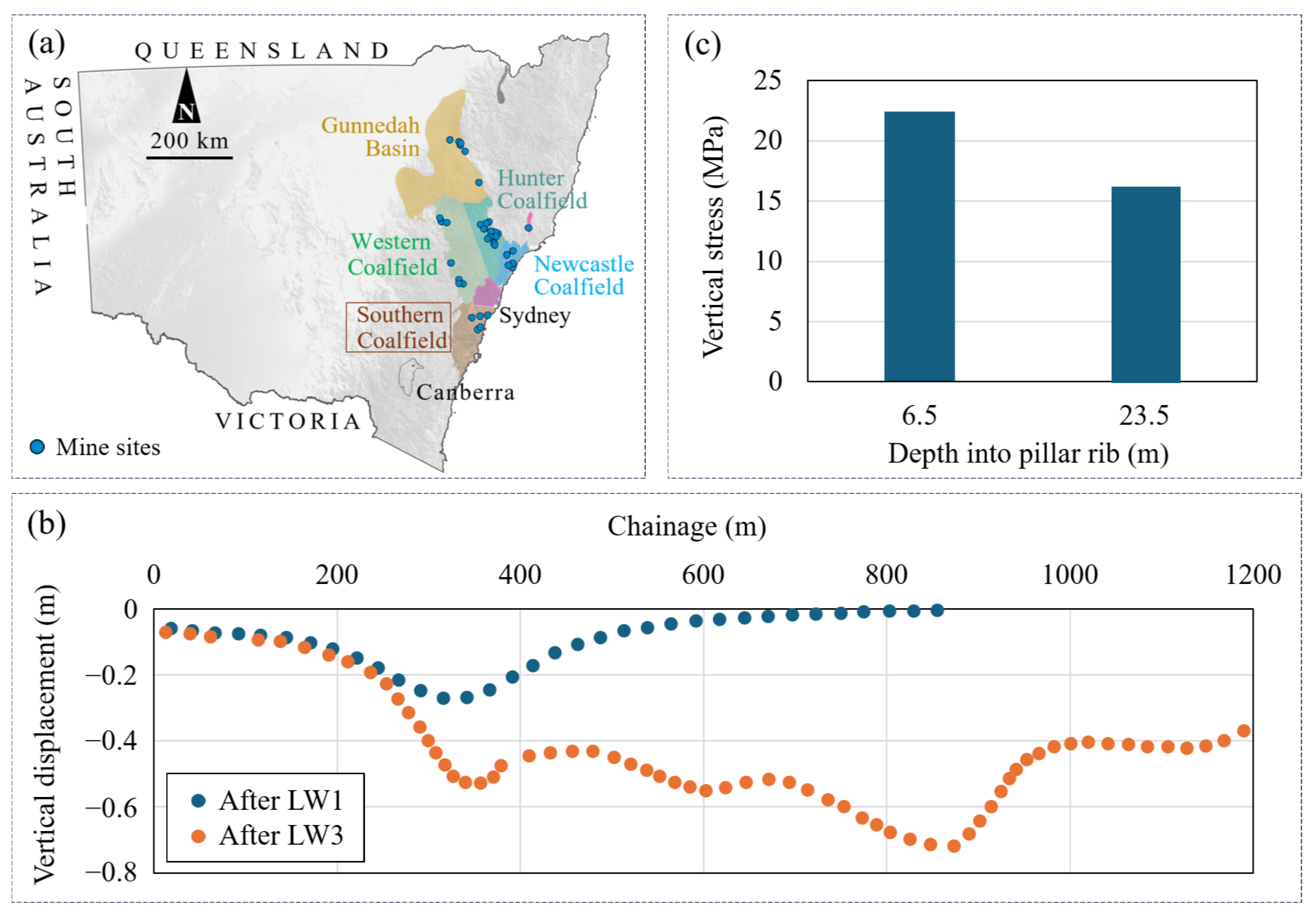
The study is based on field data obtained from a longwall coal mine located in the Southern Coalfield, New South Wales, Australia, as illustrated in Figure 1a. The site is characterised by a sequence of sedimentary strata dominated by sandstone, claystone, and mudstone, with longwall mining conducted at a depth of approximately 390 m. The Southern Coalfield is characterised by layered sedimentary strata containing bedding planes and natural joint systems, with limited faults and igneous intrusions reported. These discontinuities and structural features can locally modify stress transfer, deformation patterns, and hydraulic connectivity during longwall extraction. Mining-related ground hazards documented within the Southern Coalfield include surface subsidence, strata fracturing, valley closure, and associated disturbance to groundwater and surface-water systems [1,36,37,38,39]. In the present study area, the numerical representation focuses on the stratified rock mass, in-situ stress state, and statistically distributed high-angle natural discontinuities relevant to the observed ground response; localised major faults or igneous intrusions are not explicitly incorporated into the model. The analysed mining area comprises three sequentially extracted longwall panels (LW1–LW3), each with a mining height of approximately 2.3 m and a panel width of 235 m. Adjacent panels are separated by 40-m-wide chain pillars. Extensive geological and panel geometry data have been collected from the mine, including the stratigraphic sequence, panel layout, and in-situ stress conditions, to support the establishment of a benchmark model [40,41].
Surface subsidence data were collected, as shown in Figure 1b. In particular, subsidence profiles were measured following the extraction of longwall panels LW1 and LW3. The available field records identify these measurements by mining stage; however, the exact elapsed time between panel extraction and the corresponding surface surveys is not documented in the dataset available for this study. These profiles were obtained using peg-to-peg levelling, where survey pegs were fixed at the ground surface before mining and their vertical displacements were recorded over time, providing millimetre-level resolution of surface settlement [40,41]. The post-LW1 profile represents the ground response after extraction of the first panel, whereas the post-LW3 profile captures the cumulative response after sequential extraction of all three panels. These subsidence profiles provide direct evidence of the ground movement response to sequential panel extraction and are used in this study to validate the numerically predicted subsidence behaviour.
In addition to ground subsidence, rock stress data were also collected from two depths within the inter-panel pillar between LW1 and LW2, with the purpose of characterising stress redistribution induced by sequential panel extraction, as shown in Figure 1c. The vertical stresses were measured to be 21.8 MPa at a depth of 6.5 m and 16.8 MPa at a depth of 23.5 m. These two monitoring locations represent different positions within the chain pillar and provide information on the spatial variation in mining-induced load transfer from the pillar rib toward its interior. Both data points offer constraints on the stress concentration and load transfer mechanisms acting within the chain pillar during multi-panel mining. Together with the surface subsidence profiles, the pillar stress data provide complementary constraints for validating the numerical model against both surface deformation and internal stress responses.

3. Numerical Modelling

3.1. Model Configuration

A two-dimensional (2D) discontinuum numerical model is developed using UDEC Version 7.0 to simulate ground deformation, stress redistribution, and rock mass fracturing induced by sequential longwall panel extraction. The model is designed to capture the coupled response of the overlying strata, inter-panel pillars, and mined-out areas during successive panel extraction. A 2D representation is adopted because longwall panels typically extend hundreds to thousands of metres along the longitudinal (i.e., panel length) direction, meaning that the development of continuous fracturing and ground subsidence is primarily governed by the cross-sectional (i.e., panel width) response. Therefore, a 2D plane strain assumption is appropriate for capturing the dominant deformation mechanisms and panel-scale ground response while maintaining computational efficiency compared with 3D modelling [1,39,43].
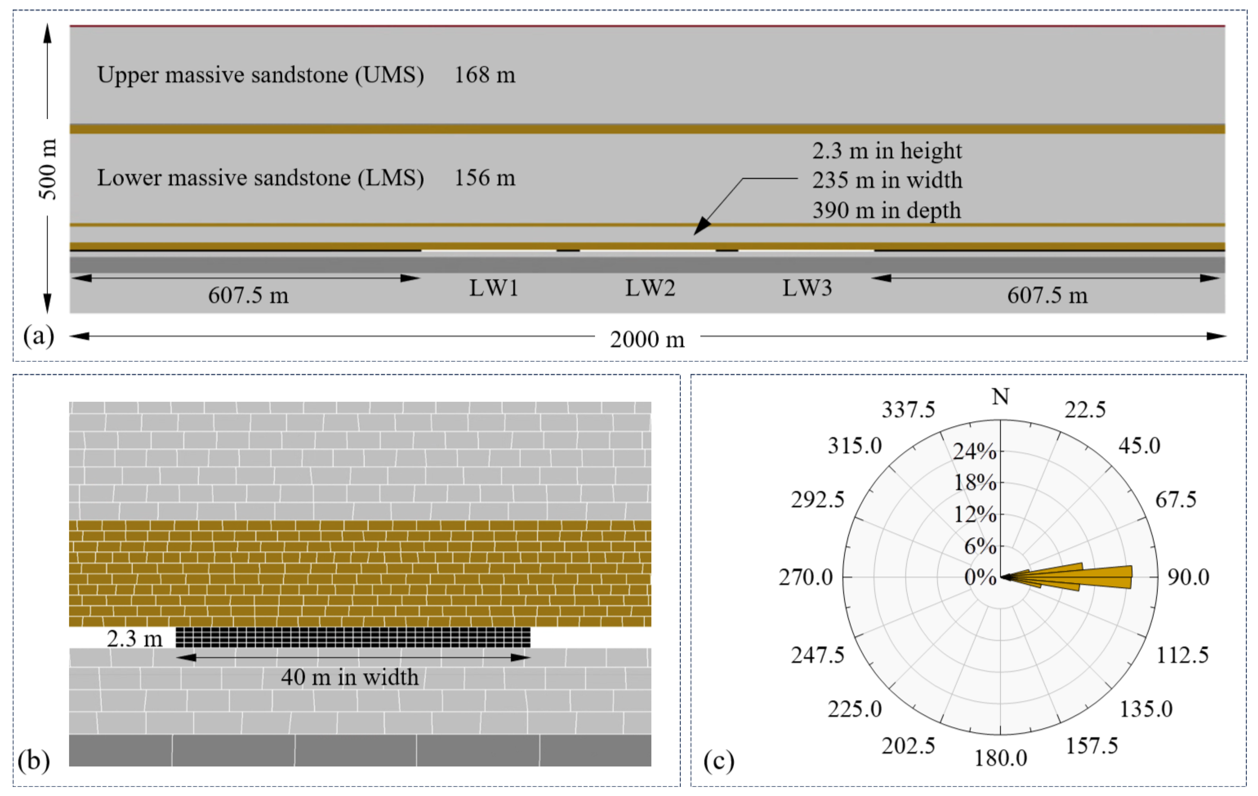
The model is established based on detailed field data regarding panel layout and stratigraphic sequence. As illustrated in Figure 2a, the model has a total width of 2000 m to accommodate three successive longwall panels. Each panel has a mining height of 2.3 m and a panel width of 235 m, with a cover depth of approximately 390 m. To minimise boundary effects, a horizontal span of 607.5 m (greater than twice the panel width) is retained on both lateral sides of the longwall domain. Adjacent panels are separated by chain pillars with a width of 40 m. The model height is 500 m, extending from 107.7 m below the coal seam to the ground surface and comprising 12 stratified rock units.
The overburden is dominated by sandstone units, typically including an upper massive sandstone (UMS) unit with a thickness of 168 m and a lower massive sandstone (LMS) unit with a thickness of 156 m. These two units are separated by a 3-m-thick mudstone layer and a 15-m-thick claystone layer. The immediate roof mainly consists of claystone, and the main roof is composed of sandstone. Based on the 2D plane strain assumption, boundary conditions are applied to the model to minimise artificial boundary effects. The bottom boundary is fully constrained by fixing both horizontal and vertical displacements. The lateral boundaries are defined as roller boundaries that restrict horizontal movement and permit vertical displacement. The upper boundary is left free to allow surface subsidence to develop. On this basis, in-situ stresses are applied throughout the model domain. The vertical stress increases linearly with depth with a gradient of 25 kPa/m, and the horizontal stress is assigned as 1.78 times the vertical stress [40]. Accordingly, the initial stress field is defined as σ v = 0.025 H and σ h = 1.78 σ v , where H is the depth below the ground surface. At the coal seam depth of approximately 390 m, the initial vertical stress is about 9.75 MPa and the corresponding horizontal stress is about 17.36 MPa. At the bottom of the model, 497.7 m below the ground surface, these values increase to 12.44 MPa and 22.14 MPa, respectively.
Rock discontinuities observed at the site are characterised by low-angle bedding planes and high-angle joints [40,43]. Horizontal joint sets are introduced to represent bedding planes. These bedding planes are explicitly assigned according to the stratigraphic structure and are therefore not controlled by a prescribed joint spacing. High-angle joints within each rock layer are generated using a Discrete Fracture Network (DFN) approach [44,45], with dip angles following a normal distribution with a mean of 90° and a standard deviation of 7.4°. The generated high-angle joint network is controlled to produce a representative block geometry with an approximate block aspect ratio of 2:1, thereby avoiding excessively elongated or unrealistically dense blocks. The DFN approach is adopted instead of conventional perpendicular joint sets. This is because it allows stochastic representation of joint orientation and spatial distribution, thereby better reflecting the inherent variability of natural rock discontinuities and avoiding artificial regular patterns that may bias deformation and fracture development in numerical analysis. A single stochastic DFN realization is retained throughout the baseline and parametric simulations so that the discontinuity configuration remains unchanged among different geometric cases, allowing the effects of panel and pillar widths to be isolated.
However, within the coal seam, vertical joints are included to facilitate accurate positioning of individual longwall panel boundaries, as shown in Figure 2b. Figure 2c shows the dip angle distribution of high-angle joints in the model, obtained by retrieving all DFN joints, where the joints have a random dip angle ranging from 67.5° to 112.5°. A single DFN realization is retained throughout the baseline and parametric simulations. The DFN is used to provide a representative statistical distribution of high-angle discontinuities rather than to reproduce an exact site-specific fracture network or to serve as a stochastic input variable. Keeping the same realization across all cases ensures that the discontinuity configuration remains unchanged, allowing the isolated effects of panel and pillar geometries to be evaluated. In addition, the discretised block size is refined near the coal seam to capture near-field rock mass behaviour, with typical block dimensions of approximately 1 m × 0.6 m in the coal seam and 2.5 m × 1.2 m in the immediate roof. Block size is gradually increased with distance from the seam to improve computational efficiency while maintaining sufficient resolution in zones impacted by mining activities.
Rock blocks are governed by the Mohr–Coulomb failure criterion, while joint behaviour is governed using the Area Coulomb Slip model. The uniaxial compressive strength and elastic modulus of rock samples are upscaled to the rock block scale using empirical size effect relationships [46,47,48]. Based on the upscaled parameters, rock mass strength properties, including cohesion, friction angle, and tensile strength, are determined using the Geological Strength Index approach [49,50]. Moreover, the normal and shear stiffnesses of joints are estimated using established empirical correlations reported by Christianson et al. [51]. In UDEC, the joint normal stiffness ( k n ) and shear stiffness ( k s ) are expressed as stress per unit displacement, with units of GPa/m. The stiffness values were estimated from the elastic properties of the surrounding rock and the characteristic dimension of the adjacent blocks following the empirical formulation of Christianson et al. [51]. The joint friction angle varies among lithological units according to the adopted rock-mass properties listed in Table 1, while joint cohesion and tensile strength are assumed to be zero [43]. These constitutive representations allow the model to capture mining-induced block movement, joint slip, stress redistribution, and progressive deformation associated with panel interaction. Accordingly, the model parameters were derived from laboratory-scale properties and established empirical relationships rather than through unconstrained numerical back-analysis. Their applicability to the analysed case was subsequently evaluated against field measurements of surface subsidence and pillar stress, as described in Section 3.2.

3.2. Model Verification

The longwall panels LW1 to LW3 are sequentially extracted by removing coal blocks within the predefined panel domains. After each extraction step, the calculation is continued until the maximum unbalanced force ratio in the model falls below 1 × 10⁻⁵, indicating that mining-induced deformation has reached a quasi-equilibrium state before the subsequent panel is excavated. Accordingly, the model represents the mechanical response at successive quasi-equilibrium mining stages rather than the actual time-dependent evolution of surface subsidence. Processes such as delayed goaf compaction, rock-mass creep, progressive pillar degradation, and long-term residual subsidence are not explicitly simulated. The calculated incremental subsidence should therefore be interpreted as extraction-induced deformation between successive mining stages, rather than as a prediction of subsidence rate or long-term post-mining settlement.
The post-mining space is not represented by a separate equivalent continuum material. Following coal-block removal, an initially open mined-out space is created, into which the overlying discontinuous rock blocks can deform, move, rotate, slip, and progressively come into contact as mining-induced stresses are redistributed. The structural characteristics of the caved zone are therefore controlled by the represented bedding planes and high-angle discontinuities described in Section 3.1. The collapsed rock blocks retain the constitutive properties of their corresponding lithological units, while their contacts are governed by the joint properties listed in Table 1. No independent goaf strength, stiffness, bulking factor, or empirical compaction law is prescribed. Instead, post-mining compaction develops implicitly through block rearrangement, contact closure, joint slip, and deformation as the model approaches quasi-equilibrium after each extraction stage.
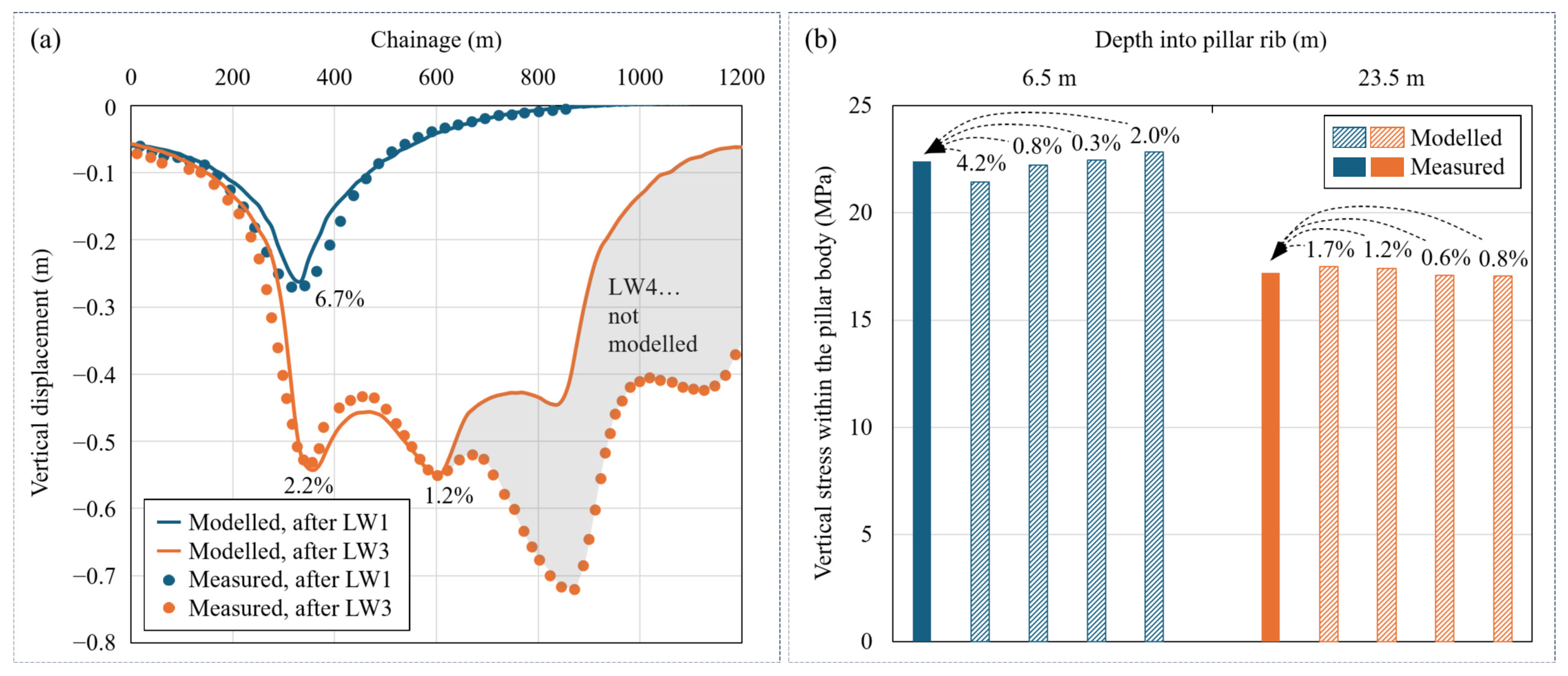
The measured surface subsidence profiles and pillar stresses were used solely for model validation and were not employed in the inverse calibration of model parameters. Model reliability is evaluated by comparing numerical predictions with available field measurements of surface subsidence and pillar stress. These validations allow the model performance to be assessed against both far-field ground movement and near-field stress redistribution. Vertical displacements are recorded along a horizontal survey line at the ground surface. Figure 3a shows a comparison between the simulated and measured subsidence profiles after the extraction of LW1 and LW3. The results indicate that the maximum subsidence following the extraction of LW1 deviates by 6.7% from the measured value, while the corresponding deviations for LW1 and LW2 following the extraction of LW3 are 2.2% and 1.2%, respectively. Overall, the comparison demonstrates that the model reproduces both the shape and magnitude of the observed subsidence troughs, with maximum subsidence above LW1 and LW2 deviating from field data by less than 10% [52,53,54]. Quantitative comparison across the complete subsidence profiles further indicates good agreement between the measured and simulated responses. For the post-LW1 profile ( n 35 ), the RMSE, MAE, mean bias, and R 2 are approximately 0.035 m, 0.028 m, −0.010 m, and 0.96, respectively. Following LW3 extraction ( n 60 ), the corresponding values are approximately 0.041 m, 0.032 m, −0.012 m, and 0.97. These indicators further demonstrate that the model reasonably reproduces both the magnitude and spatial variation in subsidence for the analysed case. These deviations can be attributed to simplifications in the numerical model, uncertainties in rock mass parameters, and potential measurement errors in the field data. In addition, the subsidence profile on the right-hand side of LW2 is excluded from the comparison, as deformation in this domain is influenced by subsequent mining activities beyond the scope of the model. These additional workings are not represented in the numerical domain, and the measured subsidence in this interval therefore reflects mining influences that are absent from the simulation. Including this section would result in a comparison between different mining conditions rather than a direct field-to-model validation. The excluded interval was defined according to the spatial extent of the external mining influence, rather than the degree of agreement between measured and simulated values. Accordingly, validation was restricted to the portion of the monitoring profile for which the field and numerical mining conditions are consistent.
Further validation is provided by stress measurements within the chain pillar separating LW1 and LW2. Based on the in-situ monitoring strategy, four observation points are placed at each of two depths (6.5 m and 23.5 m into the pillar rib), with a vertical spacing of 0.5 m, to record vertical stress variations. Figure 3b compares the simulated and measured vertical stresses at the two depths. At 6.5 m into the pillar rib, the maximum deviation of the four simulated stresses from the measured value of 21.8 MPa is approximately 4.2%. At 23.5 m into the pillar rib, the maximum deviation from the measured value of 16.8 MPa is approximately 1.7%. The close agreement at both monitoring depths indicates that the model adequately reproduces the stress concentration and load-transfer behaviour within the inter-panel pillar.
The agreement between the modelled and measured subsidence profiles and pillar stress responses indicates that the numerical model reasonably reproduces the key ground-movement and stress-response characteristics of the analysed case. Accordingly, the validated model provides a reliable basis for subsequent analyses of panel interaction, incremental subsidence, and associated rock mass responses under the geological and mining conditions represented in this study. Broader model applicability would require further validation against independent field observations from other mining conditions. The adopted strength and stiffness parameters of rock blocks and joints are listed in Table 1, where K denotes the bulk modulus, G the shear modulus, c the cohesion, φ the friction angle, t the tensile strength of rock blocks, k n the normal stiffness, k s the shear stiffness, and φ j the friction angle of rock joints.

4. Model Result Interpretation

To investigate the mechanical response of the overburden to sequential panel extraction, the results of numerical modelling are analysed in terms of both displacement and stress evolution. Particular attention is given to the LW1 domain, which is subjected to repeated disturbance from subsequent panel extractions.

4.1. Evolution in Rock Displacements

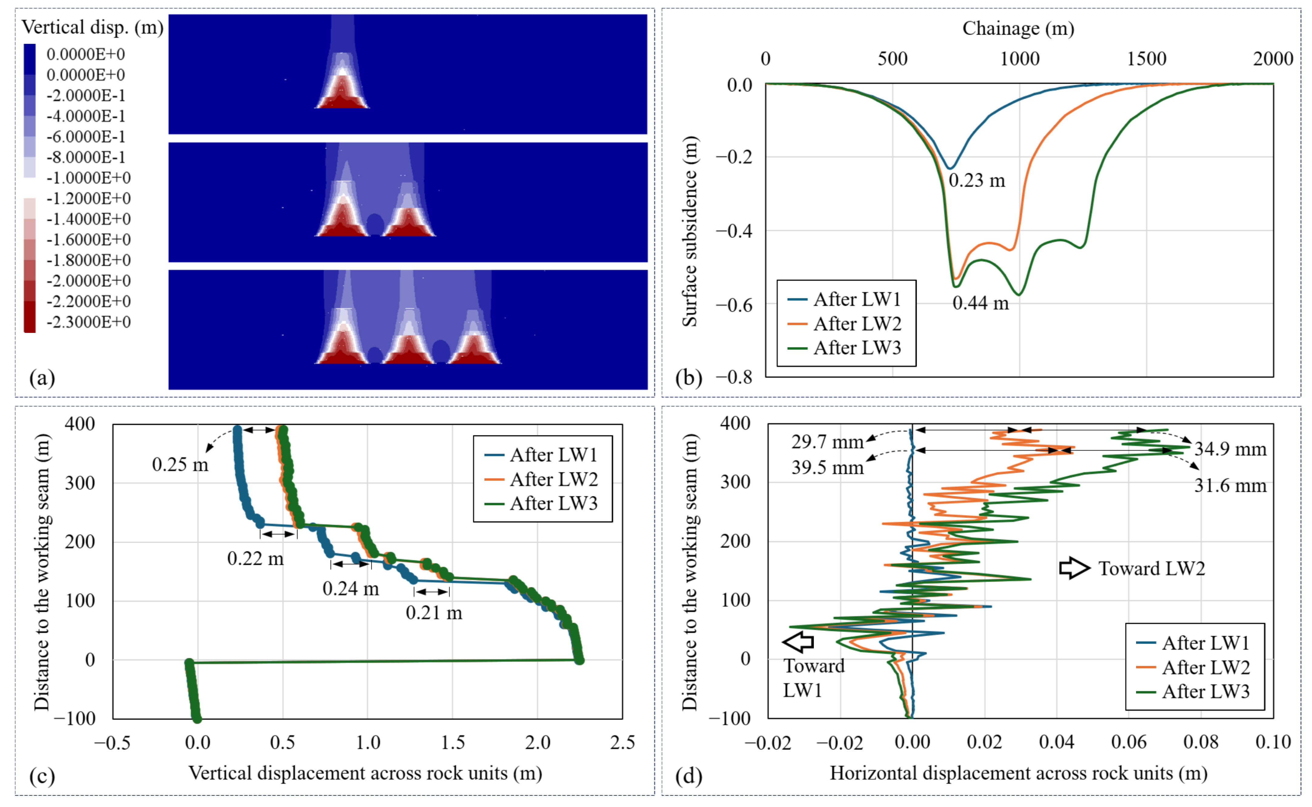
An overview of the vertical displacement fields after the extraction of longwall panels LW1, LW2, and LW3 is presented in Figure 4a, and the corresponding surface subsidence profiles recorded along the horizontal survey line are shown in Figure 4b. Both the displacement contours and subsidence profiles indicate the formation of a subsidence trough following the extraction of the first panel, accompanied by a progressive lateral expansion of the trough as subsequent panels are mined.
A vertical survey line is placed along the centreline of LW1 to examine the evolution of vertical displacements in all overlying rock units under sequential panel extractions. The results are illustrated in Figure 4c, where the vertical coordinate is expressed as the distance from the working seam for ease of comparison. The curves show that the initial surface subsidence along the LW1 centreline reaches 0.23 m after the extraction of LW1 and increases to 0.49 m after the extraction of LW2. This increase provides direct evidence of interaction between the two adjacent panels (i.e., LW1 and LW2). In contrast, the subsequent extraction of LW3 does not result in a noticeable additional subsidence above LW1, indicating that the influence of LW3 mining on the LW1 domain is limited due to the spatial separation provided by LW2. Comparison of the displacement profiles associated with LW1 and LW2 further reveals that incremental subsidence is most pronounced at the ground surface and gradually diminishes with increasing depth. At a depth of approximately 60 times the mining height above the seam, incremental subsidence becomes negligible, which may be attributed to extensive caving and fracturing in the caved and fractured zones, where rock deformation is largely completed after the first panel extraction [1,55,56].
The vertical survey line is also used to extract horizontal displacements of all rock units, as shown in Figure 4d, where positive values denote horizontal movement towards LW2 (i.e., the positive horizontal direction of the model). The results indicate that the extraction of LW1 alone induces negligible horizontal movement in the overlying strata, particularly in regions higher than 200 m above the working seam. However, the extraction of LW2 leads to pronounced horizontal displacements of the strata within the LW1 domain towards LW2. The maximum horizontal displacement reaches 39.5 mm at a depth of approximately 30 m below the ground surface and remains significant near the surface, with a value of 29.7 mm. After the extraction of LW3, horizontal displacement within the LW1 domain reaches 31.6 mm at depth and 34.9 mm near the ground surface. These changes in horizontal displacement following successive panel extraction demonstrate the cumulative influence of panel interaction on overlying rock deformation. Such a phenomenon is likely associated with stress redistribution and asymmetric loading resulting from the formation of an adjacent goaf, which drives lateral deformation of the overburden towards the newly created void.

4.2. Evolution in Stress Fields

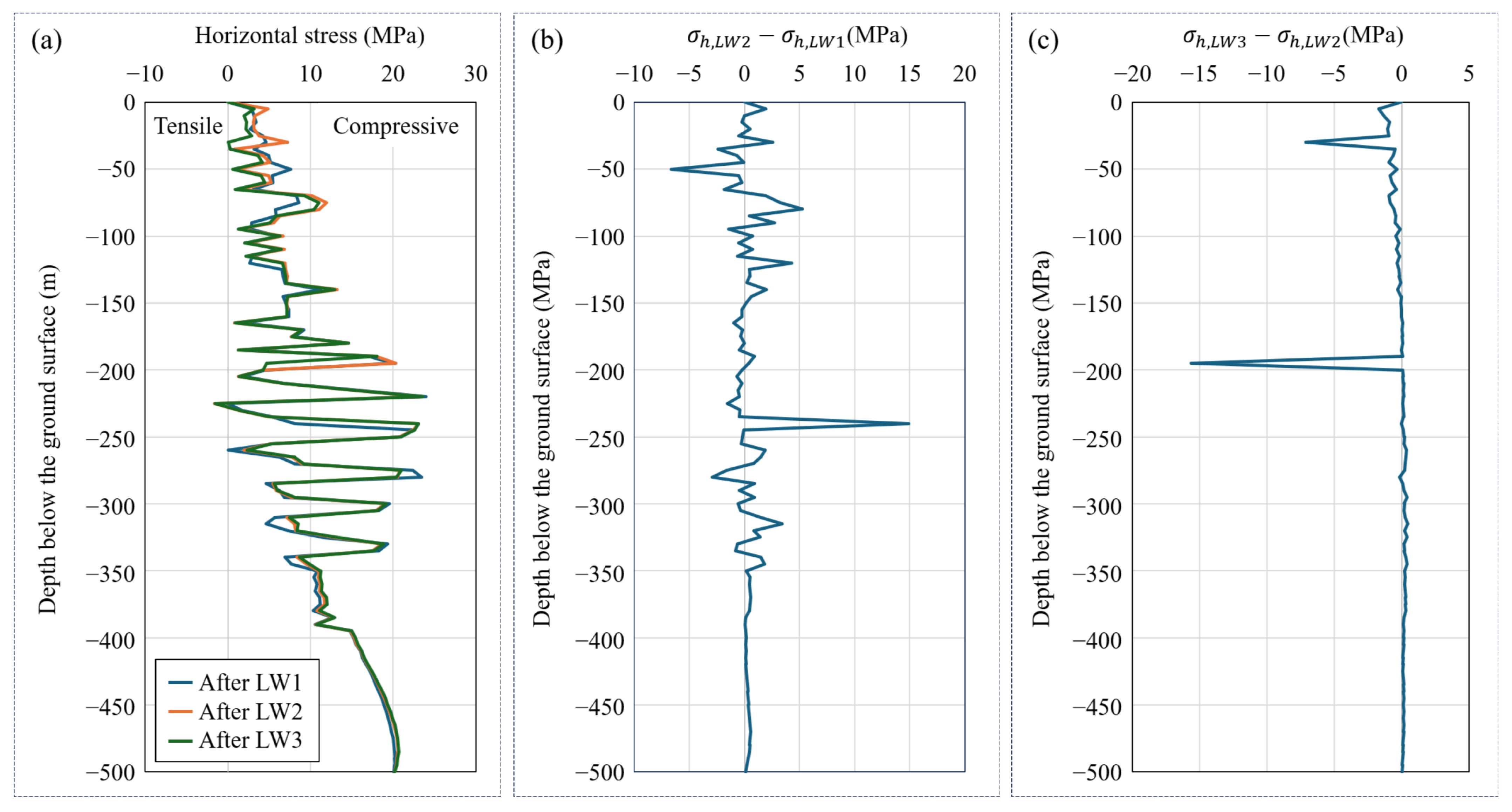
Horizontal stress is examined to characterise the continuity of stress transfer and lateral compaction within the overburden and goaf during sequential panel extraction. For this purpose, the vertical survey line is further used to extract the horizontal stress in different rock units, with three stress profiles shown in Figure 5a, where positive values denote compressive stress. A local reversal to tensile horizontal stress is observed at a depth of approximately 230 m below the ground surface. This negative value results from mining-induced unloading and differential deformation of the discontinuous overburden. As the strata bend, rotate, and locally separate following extraction, horizontal extension can develop within individual rock blocks, producing a local tensile stress state along the monitoring line. The negative stress therefore represents a localised stress-relief and extensional response of the fractured overburden rather than the initial in-situ stress condition. To quantify the variation in horizontal stress, the stress difference between the states after LW2 and after LW1 is calculated as
σ h = σ h , L W 2 σ h , L W 1
The result of Equation (1) is presented in Figure 5b, showing that σ h is positive over most depth ranges. This indicates an overall increase in horizontal compressive stress within the LW1 domain following the extraction of LW2. Such an increase can be attributed to several interacting mechanisms:
(i)
The formation of the LW2 goaf leads to a loss of load-bearing capacity in the overlying strata, causing part of the stress previously supported by LW2 to be transferred towards the mined panel LW1 through the rock arching structure and the inter-panel chain pillar. This stress transfer results in a reloading effect on the fractured rock mass within the LW1 goaf.
(ii)
Compression of the chain pillar between LW1 and LW2 induces lateral displacement of the overburden towards the LW2 domain. This lateral movement promotes secondary compaction of the fractured rock mass within the LW1 goaf, which is manifested as an increase in horizontal compressive stress.
(iii)
The goaf does not behave as a completely unloaded void but instead consists of accumulated fractured rock blocks that are capable of transmitting normal contact forces and constraining horizontal deformation. As a result, the goaf material can experience reloading and further compaction in response to stress redistribution associated with subsequent panel extraction. In the UDEC model, this compaction is represented by progressive block rearrangement, closure of discontinuities, and increased contact between fractured rock blocks. Although a three-dimensional packing density is not directly calculated in the 2D model, these changes indicate an increase in the apparent packing state of the fractured rock mass. Following LW1 extraction, the goaf retains considerable deformation capacity. Extraction of LW2 promotes further closure and secondary compaction, corresponding to the pronounced incremental subsidence above LW1. By contrast, after LW3 extraction, additional block rearrangement becomes limited because the LW1 goaf has already undergone substantial compaction and the mining-induced stress perturbation is attenuated with distance. This provides a mechanical explanation for the observed reduction in additional subsidence during the later stage of sequential extraction.
The stress difference between the post-LW2 and post-LW3 states is further evaluated and illustrated in Figure 5c. The results indicate that most rock units exhibit a reduction in horizontal stress, i.e., σ h , L W 3 σ h , L W 2 < 0 . This trend suggests that the stress response of the LW1 domain to the extraction of LW3 becomes attenuated. This attenuation can be explained by two main mechanisms:
(i)
A distance-dependent decay effect is evident. LW3 is separated from LW1 by the previously extracted panel LW2 and the inter-panel pillars, resulting in a greater spatial separation than that between LW1 and LW2. Stress redistribution induced by the extraction of LW3 primarily affects LW2 and its adjacent regions, and its influence is substantially weakened as it propagates toward LW1. As a result, the horizontal stress within the LW1 domain decreases, as reflected by σ h , L W 3 < σ h , L W 2 .
(ii)
The LW1 domain has already experienced a compaction–relaxation process during sequential mining. The initial extraction of LW1 leads to stress unloading, whereas the subsequent extraction of LW2 induces secondary compression and stress reloading. With the extraction of LW3, the entire longwall domain tends toward overall stress relaxation. At this stage, the LW1 goaf is highly fragmented and characterised by low stiffness, which limits its capacity to sustain or transmit additional horizontal stress. As a result, a reduction in horizontal stress is observed within the LW1 domain.
The results demonstrate that panel interaction in multi-panel mining is governed by a progressive redistribution and attenuation in stress, which in turn control the evolution of rock deformation and incremental subsidence. This interpretation is supported by the concurrent responses observed after LW2 extraction: horizontal compressive stress within the LW1 domain increases, horizontal displacement toward LW2 becomes pronounced, and vertical displacement and surface subsidence above LW1 increase simultaneously. The extraction of an adjacent panel (i.e., LW2) induces secondary compression and stress reloading within the previously mined LW1 domain, leading to enhanced horizontal displacement and additional surface subsidence. The consistency among these stress and displacement responses provides direct numerical evidence that lateral loading and secondary compaction of the previously mined goaf contribute to the observed incremental subsidence. However, as mining advances further to LW3, the influence on LW1 becomes weaker due to distance-dependent stress decay and the reduced stiffness of the highly fragmented goaf. This attenuation is reflected by the reduction in horizontal stress change shown in Figure 5c together with the negligible additional vertical displacement above LW1 after LW3 extraction shown in Figure 4c. These findings indicate that incremental subsidence above earlier panels is primarily driven by stress transfer and lateral compaction associated with adjacent panel extraction, while its magnitude diminishes as the mining activity progresses away from the affected area. This behaviour highlights the critical role of mining-induced stress redistribution in controlling both the extent and persistence of incremental subsidence in multi-panel mining operations.

5. Parametric Study

5.1. Experimental Scheme

To investigate the distance-dependent decay effect in multi-panel mining, a parametric study is conducted by systematically varying panel width and pillar width while keeping the cover depth and mining height constant. Panel width and pillar width are often treated as controllable design parameters in longwall mining and play a key role in regulating mining-induced ground movement and rock mass responses. In contrast, mining height and cover depth highly depend on the occurrence of coal seams at the site and are essentially fixed for the analysed panels. Therefore, both mining height and cover depth are not included as variables in the parametric study.
A full factorial set of numerical experiments is designed with panel widths ranging from 200 to 300 m and pillar widths from 15 to 75 m. These ranges are selected based on typical longwall panel and pillar geometries reported in mining operations in Australia, China, and the United States [55,57,58,59], and are intended to represent practical geometric variations around the analysed case rather than universal design limits. Mining height, cover depth, geological conditions, and in-situ stress are kept constant so that the isolated effects of panel width and pillar width can be examined. In total, 15 geometric combinations are configured, as summarised in Table 2.
For reference, conventional coal-pillar dimensioning is commonly based on a factor of safety defined as the ratio of pillar strength to the average stress acting on the pillar [60]:
F O S = S p / σ p
where S p is the pillar strength and σ p is the average pillar stress. For a rectangular coal pillar, the Mark–Bieniawski relationship may be expressed as [61]:
S p = S c [ 0.64 + 0.54 ( w / h ) 0.18 ( w 2 / L h ) ]
where S c is the in-situ coal strength, w is pillar width, L is pillar length, and h is pillar height. The average pillar stress can be estimated using a tributary-area or other appropriate load-estimation approach, and the required pillar width is then obtained by satisfying a prescribed factor of safety. These relationships show that pillar width cannot be determined from depth alone, but depends jointly on pillar geometry, coal strength, overburden loading, and the adopted stability requirement. In the present study, however, the widths listed in Table 2 are not derived as stability-design widths from Equations (2) and (3). They are selected as representative geometric cases to investigate how inter-panel spacing influences stress transfer and incremental subsidence under otherwise identical conditions. Accordingly, the equations are provided as a reference framework for comparing the investigated pillar widths with conventional pillar-design principles rather than as a design criterion adopted in the numerical experiments.
For each geometric combination, only the widths of the three longwall panels and the two inter-panel pillars are modified. The mining height, cover depth, stratigraphic sequence, material properties, boundary conditions, in-situ stress state, and DFN realization are kept unchanged. The three panels remain laterally aligned and are extracted sequentially from LW1 to LW3. When panel width or pillar width is changed, the corresponding panel and pillar boundaries are repositioned within the model while preserving the same overall modelling framework and geological structure. The lateral buffer zones are adjusted as required to maintain sufficient distance between the outermost panels and the model boundaries and thereby minimise boundary effects.
For each case, three adjacent panels are sequentially extracted using the validated numerical model. Surface subsidence is recorded for all panels, with particular emphasis on the evolution of subsidence above LW1, which serves as an indicator of the cumulative response of an earlier mined panel to subsequent extractions. Accordingly, the resulting trends should be interpreted within the geological and mining conditions represented by the case study.

5.2. Incremental Subsidence Response to Panel and Pillar Widths

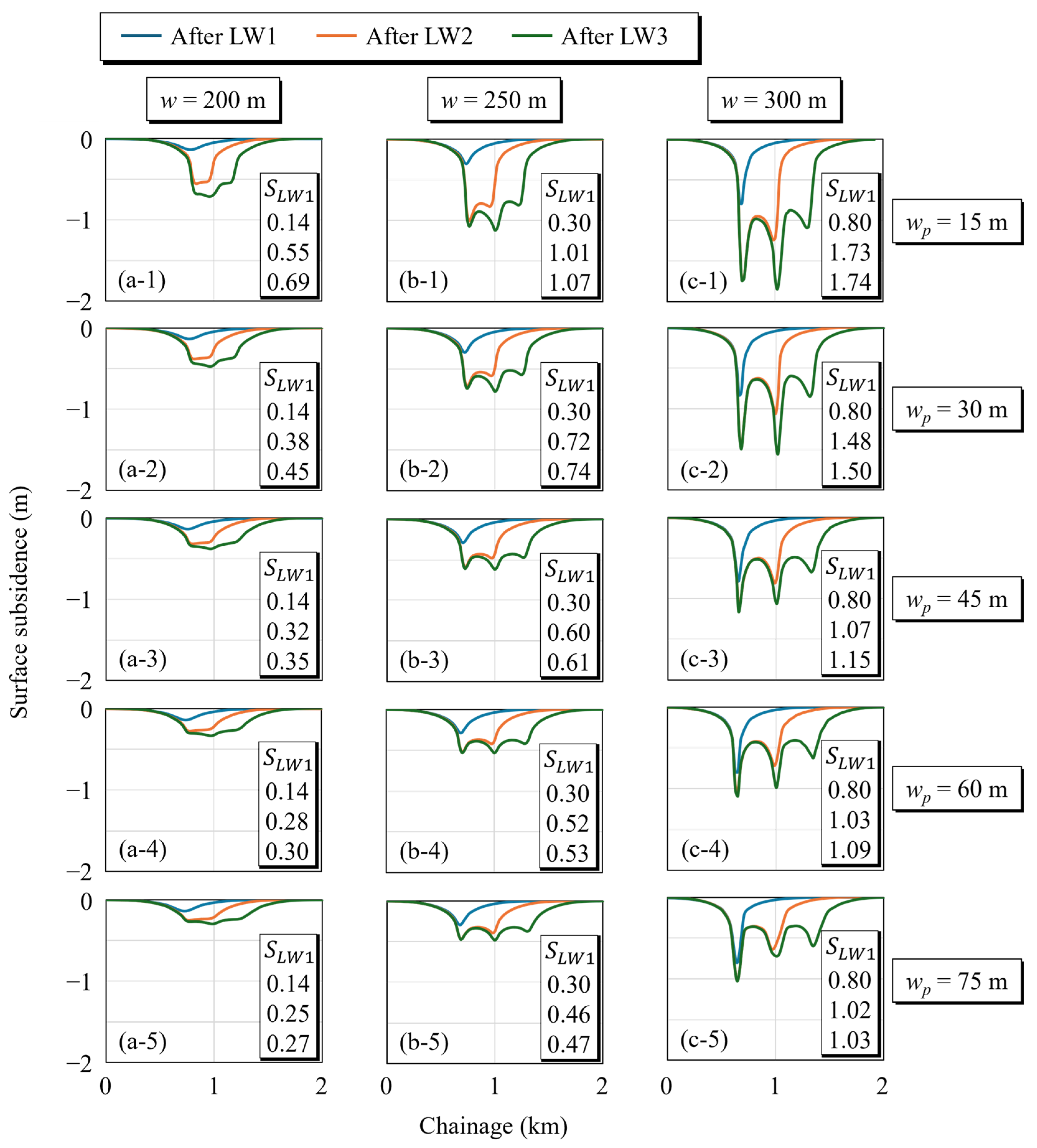
Subsidence profiles corresponding to the 15 geometric parameter combinations are presented in Figure 6. The results demonstrate that surface subsidence induced by LW1 extraction continues to evolve as subsequent panels are mined, indicating the occurrence of incremental subsidence. Figure 6a further shows that the magnitude of this additional subsidence is closely associated with pillar width. For narrow pillars (e.g., w p = 15 m), the maximum subsidence above LW1 ( S L W 1 ) increases from 0.14 m after LW1 extraction to 0.55 m after LW2 and further to 0.69 m after LW3, indicating strong mechanical interaction between adjacent panels. In contrast, when the pillar width increases to 45 m or greater, the incremental subsidence becomes much smaller. For example, for w p = 45 m, S L W 1 increases from 0.14 m to 0.32 m after LW2 and 0.35 m after LW3, while for w p = 75 m, S L W 1 increases from 0.14 m to 0.25 m and 0.27 m after LW2 and LW3, respectively. These results indicate that wider pillars provide greater mechanical separation between panels, thereby reducing stress transfer into previously mined areas and mitigating cumulative surface subsidence.
Similar trends are observed for larger panel widths of 250 m and 300 m, as shown in Figure 6b,c. The results indicate that incremental subsidence occurs across all modelled geometries, whereas its relative magnitude decreases with increasing panel width. For w = 250 m and w p = 15 m, S L W 1 increases from 0.30 m after LW1 to 1.01 m after LW2 and 1.07 m after LW3. When w p is increased to 75 m, S L W 1 reduces to 0.30 m, 0.46 m, and 0.47 m, respectively, demonstrating a significant attenuation of incremental subsidence. For the widest panels of 300 m, S L W 1 increases from 0.80 m after LW1 to 1.73 m and only slightly to 1.74 m after LW3 for w p = 15 m, while for w p = 75 m, the increase is limited to 1.02 m and 1.03 m. This feature indicates that, with increasing panel width, a greater proportion of the total subsidence is achieved during LW1 extraction, leaving limited capacity for further subsidence induced by subsequent panel extraction.
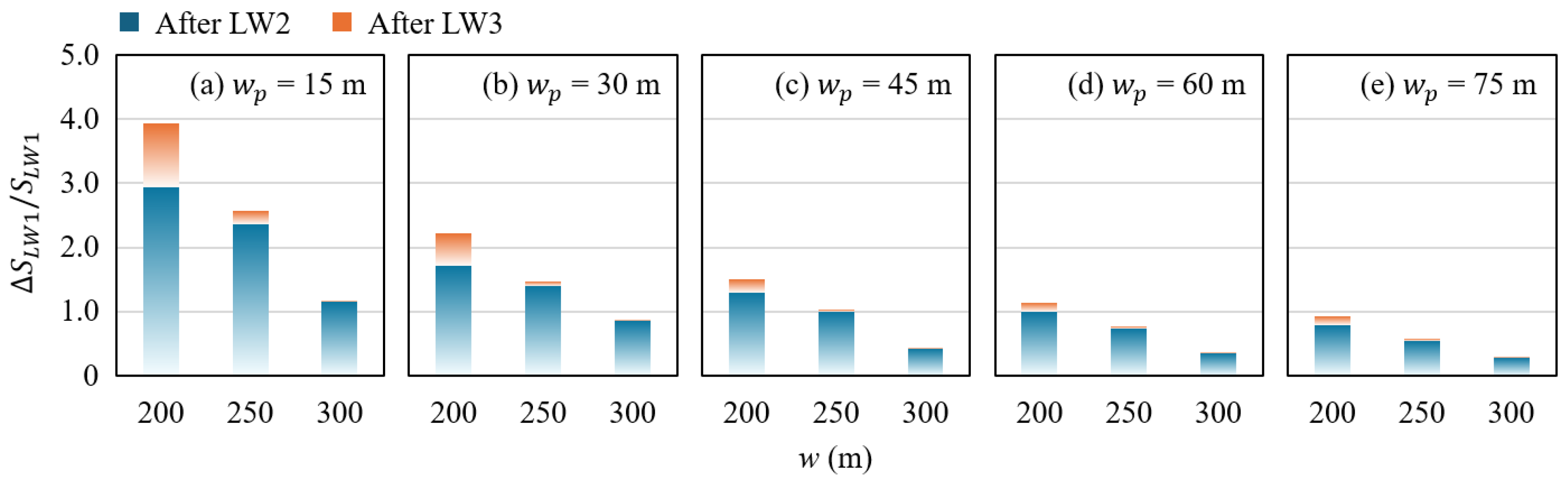
To further quantify incremental subsidence, the ratio of additional subsidence ( S L W 1 ) induced by LW2 and LW3 extraction relative to the initial LW1 subsidence ( S L W 1 ) is calculated, as presented in Figure 7. The results show that, for a given pillar width, larger panel widths are associated with smaller ratios of incremental subsidence. Mechanically, as panel width increases, the overlying rock mass experiences more extensive settlement during LW1 extraction, and the LW1 domain approaches a quasi-stable subsidence state and exhibits reduced deformation capacity during subsequent extractions. This effect is particularly evident for w = 300 m, where subsidence above LW1 after LW3 extraction remains almost unchanged compared with that after LW2 extraction.
Despite this general trend, incremental subsidence remains evident after LW2 extraction. Even for the widest panel and pillar combination (i.e., w = 300 m and w p = 75 m), the incremental subsidence induced by LW2 accounts for approximately 28% of the initial LW1 subsidence. This indicates that subsidence above LW1 is not fully developed after the first panel extraction and continues to evolve in response to adjacent panel extraction, which may be attributed to the relatively small panel width-to-cover depth ratio.
In mining practices, the ratio of panel width to cover depth is commonly used to assess whether full subsidence can occur [1,62]. Based on UK and Australian experience, the critical threshold for the ratio is typically around 1.4, with ratios above this value considered supercritical and ratios below considered subcritical. For a given mining height and geological condition, ground subsidence tends to approach a limiting value as the panel becomes supercritical and the overburden undergoes sufficiently developed caving, fracturing, and compaction. This limiting value is therefore site- and geometry-dependent rather than a universal maximum. In the present study, the maximum width-to-depth ratio is approximately 0.77, which falls well within the subcritical range. The largest subsidence obtained from the analysed cases is approximately 1.74 m for a panel width of 300 m and a pillar width of 15 m after LW3 extraction; however, this value should not be interpreted as the maximum possible subsidence for the site. As a result, the LW1 domain still remains sensitive to subsequent panel extraction, explaining why incremental subsidence is still observed even for wider panels and pillars. Secondary subsidence is therefore most likely when an earlier mined panel remains subcritical and retains residual deformation capacity, while subsequent nearby extraction induces renewed stress transfer and goaf compaction. Narrow inter-panel pillars and short mining separation favour this response, whereas wider pillars, greater separation, and a more fully compacted goaf progressively suppress further subsidence. It should be noted that this parametric study does not aim to define an exact critical threshold for full subsidence, as achieving a ratio near 1.4 under the given cover depth of 390 m would require panel widths of 546 m, which is beyond the range investigated in the present study. Furthermore, the present simulations represent quasi-equilibrium states after successive extraction stages and do not explicitly consider long-term time-dependent residual subsidence.
Long-term subsidence may nevertheless develop after mining has ceased due to time-dependent deformation of the remaining load-bearing system. In particular, creep and progressive strength degradation of inter-panel or remnant pillars may reduce their load-bearing capacity, while sustained loading may promote further compaction of fractured rock within the goaf. These processes can reactivate stress redistribution and generate delayed ground movement several years after mining. Such post-mining behaviour differs from the incremental subsidence investigated in the present study, which is induced by subsequent panel extraction. Quantifying long-term creep, pillar degradation, and delayed goaf compaction would require time-dependent constitutive models and is therefore beyond the scope of the present analysis.

5.3. Stress Response to Panel and Pillar Widths

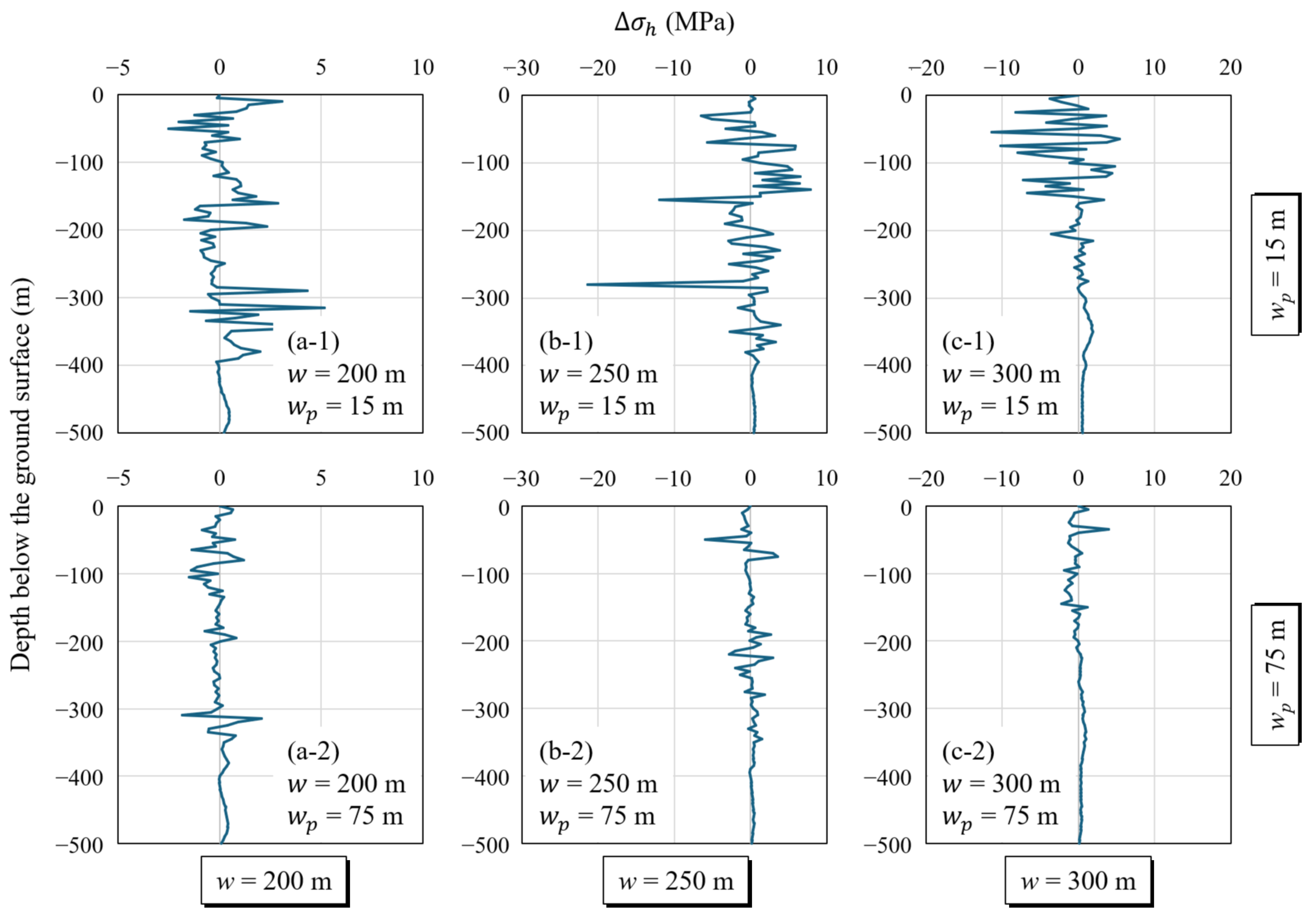
To further examine the mechanisms governing incremental subsidence, the evolution of horizontal stress within the LW1 domain is analysed using Equation (1), with results presented in Figure 8. For w = 200 m, a narrow pillar width of 15 m produces a maximum horizontal stress increase of approximately 5 MPa, with stress variation of about 3 MPa still observed in the subsurface area. In contrast, when the pillar width is increased to 75 m, the maximum stress change is reduced to about 2 MPa, and stress variations in the subsurface area become less pronounced.
A similar but more pronounced pattern is observed for w = 250 m. When w p = 15 m, the maximum horizontal stress variation reaches approximately 20 MPa, and stress changes exceeding 8 MPa extend into shallow strata. However, for w p = 75 m, the stress variation is limited to less than 6 MPa throughout the overburden, indicating substantial attenuation of stress transfer from LW2 into the LW1 domain.
For the widest panel (i.e., w = 300 m), strong panel interaction again occurs when the pillar is narrow. In the case of w p = 15 m, horizontal stress variations of up to 10 MPa develop in the shallow strata, whereas increasing the pillar width to 75 m restricts the maximum stress change to approximately 4 MPa. These results consistently demonstrate that narrow pillars promote strong stress transmission between adjacent panels, while wider pillars significantly suppress stress perturbations in previously mined areas. Mechanically, this behaviour reflects the load-transfer role of the inter-panel pillar. Narrow pillars are more prone to compression and yielding, allowing a greater proportion of the abutment stress induced by LW2 extraction to be transmitted toward the LW1 goaf. This process leads to secondary loading and compaction of the fractured rocks within the LW1 goaf, manifested as an increase in horizontal compressive stress. In contrast, wider pillars provide greater stiffness and load-bearing capacity, acting as an effective buffer that limits stress redistribution associated with the newly formed goaf.
Overall, the results reveal a clear dependence of panel interaction intensity on pillar width. Narrow pillars tend to generate stronger stress disturbances, whereas wider pillars produce a pronounced stress-shielding effect. Stress redistribution induced by adjacent panel extraction therefore constitutes a key mechanism driving panel interaction and further incremental subsidence in multi-panel longwall mining.

5.4. Parametric Sensitivity Assessment of Incremental Subsidence to Panel and Pillar Widths

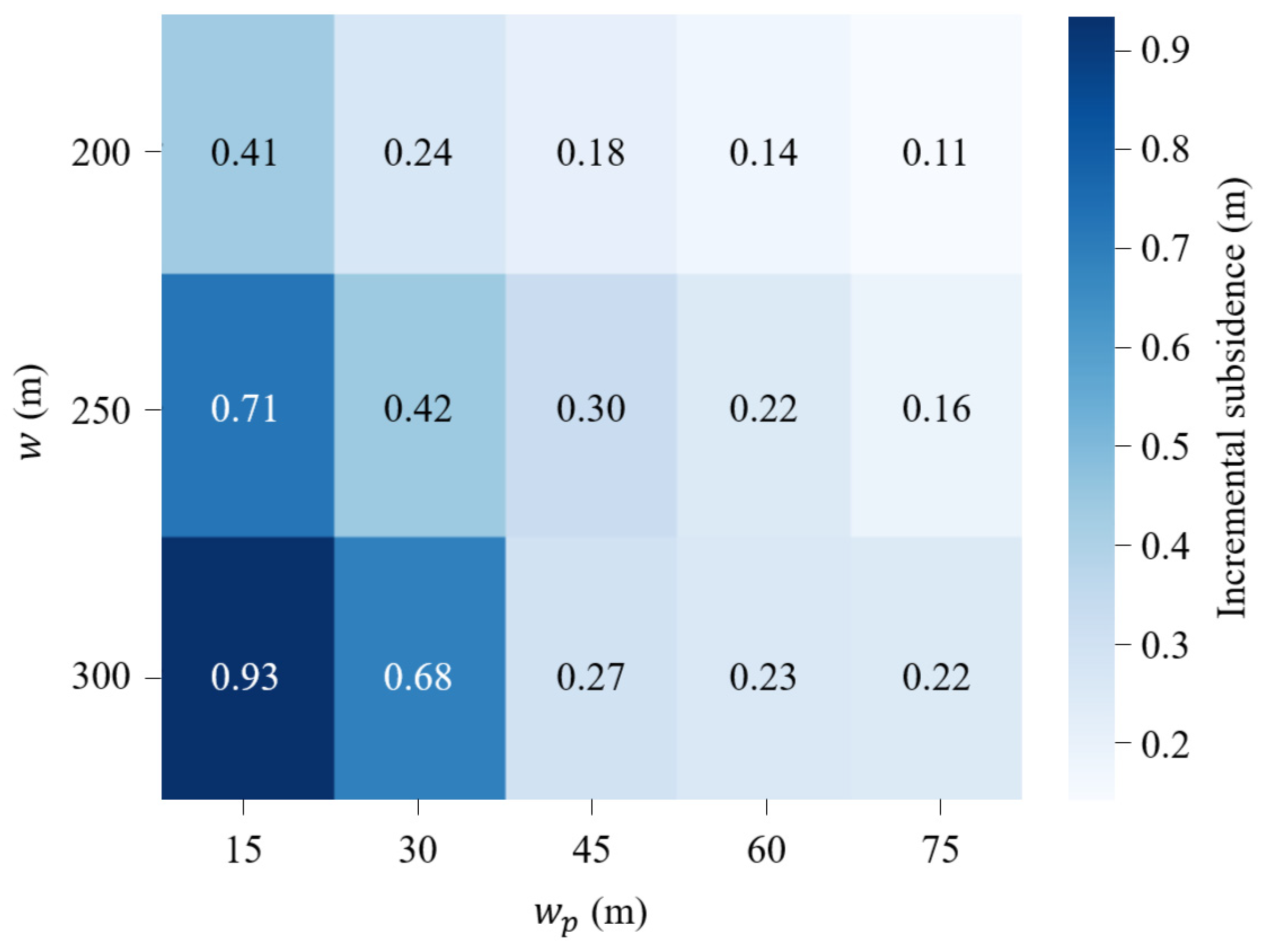
To quantify the relative influence of panel width and pillar width on incremental subsidence, a parametric sensitivity assessment is conducted using the incremental subsidence above LW1 induced by LW2 extraction, defined as
S L W 1 = S L W 2 S L W 1
where Δ S L W 1 denotes the incremental subsidence above LW1 induced by the subsequent extraction of LW2, S L W 2 denotes the maximum surface subsidence above LW1 after LW2 extraction, and S L W 1 denotes the maximum surface subsidence above LW1 after LW1 extraction. Of note is that the effect of LW3 is not considered in this analysis in order to isolate the interaction between the first two adjacent panels and focus on the primary incremental subsidence mechanism.
The calculated values of S L W 1 for all 15 geometric combinations are shown in Figure 9. To distinguish the individual effects of panel width and pillar width and quantify their interaction, a factorial regression analysis is further performed. Panel width and pillar width are normalised as
W * = W 250 50
and
P * = P 45 30
respectively, where W and P denote panel width and pillar width. The incremental subsidence response is then expressed as
Δ S = β 0 + β 1 W * + β 2 P * + β 3 W * P *
where β 1 and β 2 represent the main effects of panel width and pillar width, respectively, and β 3 represents their interaction. The fitted relationship is
Δ S = 0.348 + 0.125 W * 0.258 P * 0.117 W * P *
The regression model yields an R 2 of 0.884 and an adjusted R 2 of 0.852, indicating that approximately 87% of the variation in incremental subsidence is explained by the two geometric variables and their interaction. The fitted coefficients show a positive main effect of panel width ( β 1 = 0.125 ) and a stronger negative main effect of pillar width ( β 2 = 0.258 ). The interaction coefficient ( β 3 = 0.117 ) further indicates that the effects of panel width and pillar width are coupled rather than independent within the investigated parameter space.
The response matrix in Figure 9 is consistent with the regression results. For a fixed panel width, Δ S L W 1 decreases systematically as pillar width increases. The reduction from a pillar width of 15 m to 75 m is approximately 0.30 m for W = 200   m , 0.55 m for W = 250   m , and 0.71 m for W = 300   m . Therefore, the influence of pillar width becomes progressively stronger as panel width increases. Conversely, the variation in Δ S L W 1 with panel width is most pronounced for narrow pillars and becomes substantially smaller for wider pillars. For example, the response range across the investigated panel widths is approximately 0.52 m when P = 15   m , whereas it decreases to approximately 0.11 m when P = 75   m .
The negative interaction coefficient provides a quantitative interpretation of this coupled behaviour. Increasing panel width generally increases the magnitude of incremental subsidence, but this increase is progressively suppressed as pillar width increases. Conversely, the reduction in incremental subsidence achieved by widening the pillar becomes more pronounced for larger panels. Mechanically, panel width controls the magnitude of mining-induced stress relief and ground movement, whereas pillar width regulates the transmission of these disturbances between adjacent mining domains. Narrow pillars provide limited mechanical isolation and permit stronger stress transfer and secondary compaction within the previously mined LW1 domain, while wider pillars act as mechanical buffers that attenuate this interaction.
In actual longwall operations, the required pillar width is also influenced by factors that are not varied in the present numerical assessment [1,60,63,64], including cover depth, mining height, coal and surrounding-rock strength, discontinuity characteristics, in-situ stress conditions, and pillar loading history. Geological structures, groundwater conditions, and time-dependent deterioration may further modify pillar strength and load-transfer behaviour [37,62]. Because these factors are held constant or not explicitly represented in the present models, the pillar-width trends identified here should be interpreted as geometry-controlled responses under the investigated conditions rather than as a complete pillar-design relationship.
Within the geological, stress, and geometrical conditions investigated in this study, the parametric results indicate that pillar width becomes increasingly important as panel width increases. Increasing pillar width from 15 m to 75 m reduces Δ S L W 1 by approximately 0.30 m, 0.55 m, and 0.71 m for panel widths of 200 m, 250 m, and 300 m, respectively. This trend is consistent with the stress response, where narrow pillars generate horizontal stress variations of up to approximately 20 MPa, while wider pillars limit the variation to below about 6 MPa. Accordingly, relatively wide panels should be paired with sufficient pillar width to reduce stress transfer and secondary compaction of previously mined goaf. Conversely, narrow-pillar layouts require tighter control of panel width because the incremental subsidence response becomes more sensitive to panel geometry. These recommendations are specific to the investigated parameter range and should not be interpreted as universal pillar-design criteria.

5.5. Limitations and Future Work

Although the numerical model has been validated against both surface subsidence and pillar stress measurements, several limitations should be acknowledged. First, the present analysis adopts a 2D plane-strain representation and therefore does not explicitly account for three-dimensional effects associated with panel advance, irregular panel geometry, or along-strike geological variability. In particular, panel-end effects, spatially non-uniform abutment loading, variations in face position, and localised geological structures along the panel length are not represented. These three-dimensional effects may modify the magnitude and spatial distribution of stress transfer and subsidence, especially near panel start and finish lines or in geologically heterogeneous areas. The 2D framework is therefore most appropriate for evaluating the cross-sectional response of long panels away from panel ends, where plane-strain conditions are more representative. Second, each mining stage is evaluated under quasi-equilibrium conditions, and time-dependent processes such as creep, progressive pillar degradation, and delayed goaf compaction are not explicitly simulated. Consequently, the model is intended to evaluate mining-induced incremental subsidence between successive extraction stages rather than long-term residual subsidence after mine closure. Third, the parametric study focuses on panel width and pillar width while keeping mining height and cover depth constant, and the resulting trends should therefore be interpreted within the range of geological and mining conditions considered in this study.
The mechanical properties of the rock blocks and joints, including elastic stiffness, cohesion, friction angle, joint stiffness, and the horizontal-to-vertical stress ratio, are kept constant. These parameters may also influence stress redistribution, goaf deformation, and the resulting incremental subsidence. Their fixed values allow the effects of panel and pillar geometry to be isolated but limit the generality of the quantified relationships. No independent empirical goaf compaction law is prescribed in the model; instead, compaction develops implicitly through block rearrangement, contact closure, and joint deformation. Hydro-mechanical coupling and fluid-related effects are not included in the present model. In addition, the present study evaluates pillar width primarily in terms of its influence on stress transfer, panel interaction, and incremental subsidence, rather than pillar stability itself. An explicit pillar failure criterion and factor of safety are not included; therefore, the identified influence of pillar width should not be interpreted as a complete pillar design criterion. Future research may extend the current framework through three-dimensional and time-dependent modelling, broader multi-parameter sensitivity assessment involving geomechanical properties and in-situ stress conditions, and coupled hydro-mechanical simulations to further investigate the long-term evolution of panel interaction and cumulative ground deformation.

6. Conclusions

This paper investigates the mechanisms and controlling factors of incremental subsidence in multi-panel longwall mining. A comprehensive research methodology including field data collection and interpretation, numerical modelling, parametric study, and parametric sensitivity assessment was adopted to quantify panel interaction, stress redistribution, and incremental subsidence under varying mining conditions.
A numerical model was developed to simulate ground movement in response to sequential panel extractions. Model results demonstrate that incremental subsidence above the previously mined panels is primarily governed by stress redistribution, lateral compaction, and distance-dependent attenuation. Extraction of an adjacent panel induces secondary loading and compaction within earlier mined-out areas, enhancing horizontal displacement and additional surface subsidence. However, the effect of further extractions diminishes as inter-panel distance increases, or the previously mined-out areas become highly fragmented due to stress decay and reduced rock mass stiffness. These results indicate a progressive evolution of mining-induced deformation, in which previously disturbed rock masses may remain sensitive to subsequent extraction before gradually approaching a more stable state.
Parametric studies quantify the influence of panel and pillar widths on incremental subsidence. Narrow pillars of 15 m can produce up to 3 to 4 times greater incremental subsidence above the first panel compared with wide pillars of 75 m, highlighting the key role of pillars as mechanical buffers. Larger panel widths tend to amplify the sensitivity of incremental subsidence to pillar width, whereas wider pillars reduce its sensitivity to panel width. Stress analysis confirms these trends: narrow pillars lead to horizontal stress variations up to 20 MPa, while wider pillars limit stress redistribution to less than 6 MPa, effectively mitigating secondary loading.
From an engineering perspective, the study underscores the importance of coordinated design of panel and pillar widths to minimise cumulative surface displacement and associated ground instability risks in multi-panel mining. Within the geological, stress, and geometric conditions investigated in this study, strategic adjustment of panel and pillar configurations can reduce panel interaction, mitigate incremental subsidence, and improve the stability of overlying strata. The findings provide both mechanistic insight and case-specific guidance for evaluating panel–pillar configurations within the investigated parameter range, rather than universal design criteria for longwall operations.

Author Contributions

Conceptualization, T.L. and M.C.; methodology, T.L.; software, M.C. and W.Z.; validation, W.Z. and C.Y.; formal analysis, C.Y.; writing—original draft, T.L.; writing—review & editing, M.C.; funding acquisition, T.L. All authors have read and agreed to the published version of the manuscript.

Funding

This research was supported by the National Key Research and Development Program of China (2024YFC3909304).

Data Availability Statement

The datasets analysed in the present study are available from the corresponding author on reasonable request.

Conflicts of Interest

The authors declare no conflicts of interest.

References

  1. Chen, M.; Zhang, C.; Canbulat, I.; Saydam, S.; Fan, G.; Zhang, D. Assessment of factors and mechanism contributing to groundwater depressurisation due to longwall mining. Int. J. Coal Sci. Technol. 2024, 11, 58. [Google Scholar] [CrossRef] [Scilit]
  2. Galvin, J.M. Ground Engineering—Principles and Practices for Underground Coal Mining, 1st ed.; Springer International Publishing: Cham, Switzerland, 2016; p. 683. [Google Scholar]
  3. Bell, F.G.; Stacey, T.R.; Genske, D.D. Mining subsidence and its effect on the environment: Some differing examples. Environ. Geol. 2000, 40, 135–152. [Google Scholar] [CrossRef] [Scilit]
  4. Yin, S.; Gong, Y.; Li, Z.; Huang, L.; Wang, E.; Niu, Y.; Xie, C. Monitoring of sandstone damage and failure under graded loading and multi-crack coupling: A novel application of magnetic field signals. Theor. Appl. Fract. Mech. 2026, 144, 105573. [Google Scholar] [CrossRef] [Scilit]
  5. Chen, M.; Zhang, C.; Canbulat, I.; Saydam, S. Empirical and numerical methods for predicting continuous fracturing due to underground mining. Rock Mech. Bull. 2026, 100376. [Google Scholar] [CrossRef] [Scilit]
  6. Booth, C.J.; Spande, E.D.; Pattee, C.T.; Miller, J.D.; Bertsch, L.P. Positive and negative impacts of longwall mine subsidence on a sandstone aquifer. Environ. Geol. 1998, 34, 223–233. [Google Scholar] [CrossRef] [Scilit]
  7. Seedsman, R. Predicting vertical subsidence above chain pillars. Aust. Geomech. J. 2024, 59, 97–110. [Google Scholar] [CrossRef] [Scilit]
  8. Yin, S.; Wang, E.; Li, Z.; Zang, Z.; Liu, X.; Zhang, C.; Ding, X.; Aihemaiti, A. Multifractal and b-value nonlinear time-varying characteristics of acoustic emission for coal with different impact tendency. Measurement 2025, 248, 116896. [Google Scholar] [CrossRef] [Scilit]
  9. Chen, S.; Hu, W. A comprehensive study on subsidence control using COSFLOW. Geotech. Geol. Eng. 2009, 27, 305–314. [Google Scholar] [CrossRef] [Scilit]
  10. Ghabraie, B.; Ren, G.; Smith, J.V. Characterising the multi-seam subsidence due to varying mining configuration, insights from physical modelling. Int. J. Rock Mech. Min. Sci. 2017, 93, 269–279. [Google Scholar] [CrossRef] [Scilit]
  11. Xu, J.; Zhu, W.; Xu, J.; Wu, J.; Li, Y. High-intensity longwall mining-induced ground subsidence in Shendong coalfield, China. Int. J. Rock Mech. Min. Sci. 2021, 141, 104730. [Google Scholar] [CrossRef] [Scilit]
  12. Alejano, L.R.; RamíRez-Oyanguren, P.; Taboada, J. FDM predictive methodology of subsidence due to flat and inclined coal seam mining. Int. J. Rock Mech. Min. Sci. 1999, 36, 475–491. [Google Scholar] [CrossRef] [Scilit]
  13. Pan, R.; Li, Y.; Wang, H.; Chen, J.; Xu, Y.; Yang, H.; Cao, S. A new model for the identification of subcritical surface subsidence in deep pillarless mining. Eng. Fail. Anal. 2021, 129, 105631. [Google Scholar] [CrossRef] [Scilit]
  14. Zhu, X.; Guo, G.; Liu, H.; Yang, X. Surface subsidence prediction method of backfill-strip mining in coal mining. Bull. Eng. Geol. Environ. 2019, 78, 6235–6248. [Google Scholar] [CrossRef] [Scilit]
  15. Wang, J.W.; Ma, D.L.; Zhou, Y.F. Study on the visual prediction and analysis method of mining subsidence. Adv. Mater. Res. 2012, 402, 724–727. [Google Scholar]
  16. Ghabraie, B.; Ren, G.; Barbato, J.; Smith, J.V. A predictive methodology for multi-seam mining induced subsidence. Int. J. Rock Mech. Min. Sci. 2017, 93, 280–294. [Google Scholar] [CrossRef] [Scilit]
  17. Pariseau, W.; Wempen, J. Comparison of mine subsidence estimates from finite element modeling with dinsar observations. In ARMA US Rock Mechanics/Geomechanics Symposium; ARMA: Prague, Czech Republic, 2020. [Google Scholar]
  18. Wang, J.; Wu, S.; Wang, Z.; Barbaryka, A.; Tost, M.; Li, M. New prediction method of subsidence based on the numerical displacement analysis: A study case of deep-buried thick alluvial layer and thin bedrock. Rock Mech. Rock Eng. 2025, 58, 6723–6744. [Google Scholar] [CrossRef] [Scilit]
  19. Zhou, B.; Yan, Y.; Kang, J. Dynamic prediction model for progressive surface subsidence based on MMF time function. Appl. Sci. 2023, 13, 8066. [Google Scholar] [CrossRef] [Scilit]
  20. Chen, M.; Zhang, C.; Huang, C.; Canbulat, I. Mechanism-informed data-driven forecasting of roof cavities in longwall mining. Int. J. Rock Mech. Min. Sci. 2026, 207, 106704. [Google Scholar] [CrossRef] [Scilit]
  21. Yang, X.; Wen, G.; Dai, L.; Sun, H.; Li, X. Ground subsidence and surface cracks evolution from shallow-buried close-distance multi-seam mining: A case study in bulianta coal mine. Rock Mech. Rock Eng. 2019, 52, 2835–2852. [Google Scholar] [CrossRef] [Scilit]
  22. Zhu, H.; Wang, H.; Gao, R.; Zhao, Y. Surface subsidence characteristics of mining panel layout configuration with multi-seam longwall mining. Processes 2023, 11, 1590. [Google Scholar] [CrossRef] [Scilit]
  23. Xie, P.; Luo, Y.; Wu, Y.; Gao, X.; Luo, S.; Zeng, Y. Roof deformation associated with mining of two panels in steeply dipping coal seam using subsurface subsidence prediction model and physical simulation experiment. Min. Metall. Explor. 2020, 37, 581–591. [Google Scholar] [CrossRef] [Scilit]
  24. Zhang, Q.; Guo, Z.; Wang, M.; Mei, J.; Liu, L.; Ashraf, T.; Wang, X. InSAR-based multi-source monitoring and modeling of multi-seam mining-induced deformation and hazard chain evolution in the loess gully region. Remote Sens. 2025, 17, 3993. [Google Scholar] [CrossRef] [Scilit]
  25. Zhang, C.; Tu, S.; Zhao, Y. Compaction characteristics of the caving zone in a longwall goaf: A review. Environ. Earth Sci. 2019, 78, 27. [Google Scholar] [CrossRef] [Scilit]
  26. Yavuz, H. An estimation method for cover pressure re-establishment distance and pressure distribution in the goaf of longwall coal mines. Int. J. Rock Mech. Min. Sci. 2004, 41, 193–205. [Google Scholar] [CrossRef] [Scilit]
  27. Wang, P.; Zhao, J.; Feng, G.; Wang, Z. Interaction between vertical stress distribution within the goaf and surrounding rock mass in longwall panel systems. J. S. Afr. Inst. Min. Metall. 2018, 118, 745. [Google Scholar] [CrossRef] [Scilit]
  28. Xu, J.; Gao, M.; Wang, Y.; Yu, Z.; Zhao, J.; DeJong, M.J. Numerical investigation of the effects of separated footings on tunnel-soil-structure interaction. J. Geotech. Geoenviron. Eng. 2025, 151, 04025057. [Google Scholar] [CrossRef] [Scilit]
  29. Suchowerska, A.; Carter, J.P.; Merifield, R.S. Horizontal stress under supercritical longwall panels. Int. J. Rock Mech. Min. Sci. 2014, 70, 240–251. [Google Scholar] [CrossRef] [Scilit]
  30. Shabanimashcool, M.; Li, C.C. A numerical study of stress changes in barrier pillars and a border area in a longwall coal mine. Int. J. Coal Geol. 2013, 106, 39–47. [Google Scholar] [CrossRef] [Scilit]
  31. Eremin, M.; Peryshkin, A.; Esterhuizen, G.; Pavlova, L.; Fryanov, V. Numerical analysis of pillar stability in longwall mining of two adjacent panels of an inclined coal seam. Appl. Sci. 2022, 12, 11028. [Google Scholar] [CrossRef] [Scilit]
  32. Yetkin, M.E.; Ozfirat, M.K.; Onargan, T. Examining the optimum panel pillar dimension in longwall mining considering stress distribution. Sci. Rep. 2024, 14, 6928. [Google Scholar] [CrossRef] [Scilit] [PubMed]
  33. Ning, S.; Zhu, W.; Gao, J.; Qin, W.; Xu, G.; Xu, J. A carbon fiber-based self-sensing approach for monitoring damage evolution in coal pillars. Int. J. Rock Mech. Min. Sci. 2026, 202, 106506. [Google Scholar] [CrossRef] [Scilit]
  34. Chen, M.; Fan, G.; Zhang, D.; Zhang, S.; Zhang, W. Assessing squeezing ground conditions in pillar basement due to mining and a squeezing control strategy. Bull. Eng. Geol. Environ. 2025, 84, 379. [Google Scholar] [CrossRef] [Scilit]
  35. Sakhno, I.; Sakhno, S.; Skrzypkowski, K.; Isaienkov, O.; Zagórski, K.; Zagórska, A. Floor heave control in gob-side entry retaining by pillarless coal mining with anti-shear pile technology. Appl. Sci. 2024, 14, 4992. [Google Scholar] [CrossRef] [Scilit]
  36. Barbato, J.; Hebblewhite, B.; Mitra, R.; Mills, K. Prediction of horizontal movement and strain at the surface due to longwall coal mining. Int. J. Rock Mech. Min. Sci. 2016, 84, 105–118. [Google Scholar] [CrossRef] [Scilit]
  37. Holla, L.; Buizen, M. The ground movement, strata fracturing and changes in permeability due to deep longwall mining. Int. J. Rock Mech. Min. Sci. Geomech. Abstr. 1991, 28, 207–217. [Google Scholar] [CrossRef] [Scilit]
  38. Zhang, C.; Mitra, R.; Oh, J.; Hebblewhite, B. Analysis of mining-induced valley closure movements. Rock Mech. Rock Eng. 2016, 49, 1923–1941. [Google Scholar] [CrossRef] [Scilit]
  39. Zhang, C.; Mitra, R.; Oh, J.; Canbulat, I.; Hebblewhite, B. Numerical analysis on mining-induced fracture development around river valleys. Int. J. Min. Reclam. Environ. 2018, 32, 463–485. [Google Scholar] [CrossRef] [Scilit]
  40. Gale, W. Review of the Hydraulic Conductivity and Geotechnical Characteristics of the Overburden at Tahmoor South; TAH4083; SCT Operations: Wollongong, NSW, Australia, 2013; pp. 1–274. Available online: https://www.tahmoorcolliery.com.au/wp-content/uploads/sites/8/2022/10/08.-Tahmoor-South-Coal_EIS_App-G_Geotechnical.pdf (accessed on 1 January 2026).
  41. Mills, K.; Blacka, B. Longwall 10A Height of Fracture Borehole for Tahmoor South Project—Observations, Measurements, and Interpretation; SCT Operations: Wollongong, NSW, Australia, 2014; pp. 1–125. Available online: https://www.tahmoorcolliery.com.au/wp-content/uploads/sites/8/2022/10/08.-Tahmoor-South-Coal_EIS_App-G_Geotechnical.pdf (accessed on 1 January 2026).
  42. Resources, N. Outcropping Sedimentary Basins in NSW. 2024. Available online: https://meg.resourcesregulator.nsw.gov.au/geological-survey/geology/sedimentary-basins (accessed on 1 January 2026).
  43. Chen, M.; Zhang, C.; Canbulat, I.; Saydam, S. Assessment of groundwater depressurisation due to mining considering flow nonlinearity in connected fractures. Rock Mech. Rock Eng. 2025, 58, 4347–4376. [Google Scholar] [CrossRef] [Scilit]
  44. Lei, Q.; Latham, J.P.; Tsang, C.F. The use of discrete fracture networks for modelling coupled geomechanical and hydrological behaviour of fractured rocks. Comput. Geotech. 2017, 85, 151–176. [Google Scholar] [CrossRef] [Scilit]
  45. Yin, T.; Chen, Q. Simulation-based investigation on the accuracy of discrete fracture network (DFN) representation. Comput. Geotech. 2020, 121, 103487. [Google Scholar] [CrossRef] [Scilit]
  46. Yoshinaka, R.; Osada, M.; Park, H.; Sasaki, T.; Sasaki, K. Practical determination of mechanical design parameters of intact rock considering scale effect. Eng. Geol. 2008, 96, 173–186. [Google Scholar] [CrossRef] [Scilit]
  47. Pratt, H.R.; Black, A.D.; Brown, W.S.; Brace, W.F. The effect of specimen size on the mechanical properties of unjointed diorite. Int. J. Rock Mech. Min. Sci. Geomech. Abstr. 1972, 9, 513–516. [Google Scholar] [CrossRef] [Scilit]
  48. Yin, S.; Li, Z.; Wang, E.; Niu, Y.; Tian, H.; Li, X.; Li, H.; Yang, C. The infrared thermal effect of coal failure with different impact types and its relationship with bursting liability. Infrared Phys. Technol. 2024, 138, 105263. [Google Scholar] [CrossRef] [Scilit]
  49. Hoek, E.; Carranza-Torres, C.; Corkum, B. Hoek-Brown Failure Criterion—2002 Edition; NARMS-Tac Conference; University of Toronto Press: Toronto, Canada, 2002. [Google Scholar]
  50. Sonmez, H.; Gokceoglu, C.; Ulusay, R. Indirect determination of the modulus of deformation of rock masses based on the GSI system. Int. J. Rock Mech. Min. Sci. 2004, 41, 849–857. [Google Scholar] [CrossRef] [Scilit]
  51. Christianson, M.; Board, M.; Rigby, D. UDEC Simulation of Triaxial Testing of Lithophysal Tuff; 41st US Symposium on Rock Mechanics (USRMS); OnePetro: Golden, CO, USA, 2006. [Google Scholar]
  52. Bahrani, N.; Hadjigeorgiou, J. Influence of stope excavation on drift convergence and support behavior: Insights from 3D continuum and discontinuum models. Rock Mech. Rock Eng. 2018, 51, 2395–2413. [Google Scholar] [CrossRef] [Scilit]
  53. Gao, F.; Stead, D.; Kang, H. Numerical simulation of squeezing failure in a coal mine roadway due to mining-induced stresses. Rock Mech. Rock Eng. 2015, 48, 1635–1645. [Google Scholar] [CrossRef] [Scilit]
  54. Zhang, G.; Chen, L.; Wen, Z.; Chen, M.; Tao, G.; Li, Y.; Zuo, H. Squeezing failure behavior of roof-coal masses in a gob-side entry driven under unstable overlying strata. Energy Sci. Eng. 2020, 8, 2443–2456. [Google Scholar] [CrossRef] [Scilit]
  55. Chen, M.; Zhang, C.; Canbulat, I.; Saydam, S. An enhanced empirical model for predicting continuous fracturing in rock masses. Rock Mech. Rock Eng. 2024, 58, 4321–4346. [Google Scholar] [CrossRef] [Scilit]
  56. Kendorski, F.S.; Khosla, I.; Singh, M.M. Criteria for determining when a body of surface water constitutes a hazard to mining. In Final Report to US Bureau of Mines; Engineers International: Arlington, VA, USA, 1979; pp. 1–363. [Google Scholar]
  57. Ditton, S. Empirical Subsidence Prediction Model Details; DGS Report No. DgS-001/7; Ditton Geotechnical Services: Charlestown, NSW, Australia, 2015; pp. 1–183. Available online: https://whitehavencoal.com.au/wp-content/uploads/2019/08/NAR-Extraction-Plan-EP-LW101-to-LW106-Appendix-B-Subsidence-Predictions-3.pdf (accessed on 1 January 2026).
  58. Tammetta, P. Estimation of the height of complete groundwater drainage above mined longwall panels. Groundwater 2013, 52, 723–734. [Google Scholar] [CrossRef] [Scilit] [PubMed]
  59. Mark, C. Analysis of longwall pillar stability (ALPS): An update. In Proceedings of the Workshop on Coal Pillar Mechanics and Design; Bureau of Mines: Washington, DC, USA, 1992. [Google Scholar]
  60. Reed, G.; Mctyer, K.; Frith, R. An assessment of coal pillar system stability criteria based on a mechanistic evaluation of the interaction between coal pillars and the overburden. Int. J. Min. Sci. Technol. 2017, 27, 9–15. [Google Scholar] [CrossRef] [Scilit]
  61. Poulsen, B.A.; Adhikary, D.P. A numerical study of the scale effect in coal strength. Int. J. Rock Mech. Min. Sci. 2013, 63, 62–71. [Google Scholar] [CrossRef] [Scilit]
  62. Whittaker, B.N.; Reddish, D.J. Influence of geological factors on the character of mining subsidence. In Subsidence: Occurrence, Prediction and Control; Whittaker, B.N., Reddish, D.J., Eds.; Elsevier: New York, NY, USA, 1989; pp. 315–357. [Google Scholar]
  63. Poulsen, B.A. Coal pillar load calculation by pressure arch theory and near field extraction ratio. Int. J. Rock Mech. Min. Sci. 2010, 47, 1158–1165. [Google Scholar] [CrossRef] [Scilit]
  64. Frith, R.; Reed, G. Limitations and potential design risks when applying empirically derived coal pillar strength equations to real-life mine stability problems. Int. J. Min. Sci. Technol. 2019, 29, 17–25. [Google Scholar] [CrossRef] [Scilit]
Figure 1. Field data collection. (a) Mine location, modified from reference [42]. (b) Measured surface subsidence profiles after the extraction of panels LW1 and LW3. (c) Measured vertical stresses at two points within the pillar.
Applsci 16 09052 g001
Figure 2. Model configuration. (a) Geometry of panels, pillars, and critical rock units. (b) Close-up view of staggered rock blocks generated by horizontal bedding planes and high-angle joints. (c) Dip angle distribution of high-angle joints in the model.
Applsci 16 09052 g002
Figure 3. Model verification through comparisons between simulated and measured (a) surface subsidence profiles after the extraction of LW1 and LW3 and (b) vertical stresses within the pillar between LW1 and LW2 at depths of 6.5 m and 23.5 m into the pillar rib.
Applsci 16 09052 g003
Figure 4. Analysis of mining-induced ground movement. (a) Overview of vertical displacement fields after the extraction of panels LW1, LW2, and LW3. (b) Evolution of surface subsidence profiles. (c) Vertical displacements across all rock units. (d) Horizontal displacements across all rock units.
Applsci 16 09052 g004
Figure 5. Analysis of mining-induced stress evolution. (a) Horizontal stress profiles across all rock units. (b) Variation in horizontal stress within the LW1 domain between the states after LW1 ( σ h , L W 1 ) and after LW2 ( σ h , L W 2 ). (c) Change in horizontal stress within the LW1 domain between the states after LW2 ( σ h , L W 2 ) and after LW3 ( σ h , L W 3 ).
Applsci 16 09052 g005
Figure 6. Surface subsidence profiles illustrating the evolution of incremental subsidence above LW1 for panel widths ( w ) of (a-1a-5) 200 m, (b-1b-5) 250 m, and (c-1c-5) 300 m and varying pillar widths ( w p ).
Applsci 16 09052 g006
Figure 7. Ratio of subsidence increments ( S L W 1 ) to initial subsidence ( S L W 1 ) under pillar widths of (a) 15 m, (b) 30 m, (c) 45 m, (d) 60 m, and (e) 75 m.
Applsci 16 09052 g007
Figure 8. Horizontal stress variation ( σ h ) under panel widths ( w ) of (a-1,a-2) 200 m, (b-1,b-2) 250 m, and (c-1,c-2) 300 m and varying pillar widths ( w p ).
Applsci 16 09052 g008
Figure 9. Incremental subsidence ( S L W 1 ) responses to different panel and pillar widths.
Applsci 16 09052 g009
Table 1. Rock strength and stiffness parameters adopted in the verified model [43].
ID.LithologyThickness (m)Rock BlocksRock Joints
K (GPa) G (GPa) c (MPa) φ (°) t (MPa) k n (GPa/m) k s (GPa/m) φ j (°)
1Shale24.643.206.6444.835.0026.722.6737.36
2Massive sandstone1687.625.256.0453.862.3529.232.9244.88
3Mudstone34.643.206.9436.985.0026.722.6730.82
4Claystone155.483.779.2132.468.8531.523.1527.05
5Massive sandstone1567.625.257.6747.282.3529.232.9239.40
6Claystone65.904.069.5629.438.8539.613.9624.52
7Sandstone287.625.258.5545.052.3529.232.9237.54
8Claystone125.904.069.6528.898.8528.292.8324.07
9Coal2.34.672.676.5139.111.6628.782.8832.60
10Sandstone9.77.625.258.8444.412.3529.232.9237.01
11Sandstone287.625.259.0144.062.3529.232.9236.72
12Sandstone709.016.2010.4044.482.7834.563.4637.07
Table 2. Widths of panels and pillars for parametric study.
Experiment IDPanel Width (m)Pillar Width (m)
120015
230
345
460
575
625015
730
845
960
1075
1130015
1230
1345
1460
1575
Disclaimer/Publisher’s Note: The statements, opinions and data contained in all publications are solely those of the individual author(s) and contributor(s) and not of MDPI and/or the editor(s). MDPI and/or the editor(s) disclaim responsibility for any injury to people or property resulting from any ideas, methods, instructions or products referred to in the content.