1. Introduction
Winter snow and ice events substantially increase road safety risks and associated socioeconomic losses. The incidence of traffic accidents under snow- and ice-covered conditions may be approximately 90% higher than under normal conditions [
1]. Between 1949 and 2000, 155 damaging snowstorms in the United States caused total economic losses of approximately USD 21.6 billion [
2]. In early 2012, a prolonged cold wave accompanied by snowfall caused major casualties across several European countries, with an estimated death toll of approximately 800 [
3]. During the winter of 2023/2024, severe cold, snowfall, and freezing rain events in eastern China affected approximately 6.36 million people and caused direct economic losses of CNY 19.75 billion [
4].
The impacts of snow and ice events are closely related to the timeliness and effectiveness of road clearance operations. Following snowfall or freezing rain, delays in removing snow and ice and restoring roadway capacity can lead to progressive reductions in pavement friction and substantial disruption to traffic operations. These conditions may trigger clusters of traffic accidents, widespread congestion, and regional transport network interruptions, thereby amplifying the cascading impacts of the original weather event [
5].
Under the combined effects of environmental exposure and vehicle loading, snow accumulated on pavement surfaces undergoes repeated freeze–thaw cycles and progressive compaction [
6,
7], gradually transforming from loose fresh snow into a highly compacted snow and ice layer. The strong bond that develops at the ice–pavement interface substantially increases the difficulty of mechanical fracture and removal. Meanwhile, the pavement friction coefficient may decrease by approximately 70%, further increasing the risks of skidding and braking failure and posing a serious threat to winter road safety [
8,
9].
To meet the demand for efficient removal under complex snow and ice conditions, road snow and ice control has progressively shifted from conventional manual operations to mechanized and system-oriented approaches. Technological development has increasingly focused on improving operational efficiency and adaptability across variable and demanding winter conditions.
Before the mid-twentieth century, road snow removal relied primarily on manual labor. This approach was labor-intensive and inefficient and was therefore suitable only for localized sections of low-traffic roads [
10]. During the 1950s, the rapid expansion of motorized transport made manual snow removal increasingly inadequate, prompting the development and application of mechanized equipment for clearing loose snow from urban roads and major highways [
11]. In the 1960s, chemical deicing methods—particularly deicing salts—were widely adopted in North America and Europe because of their rapid action and relatively low cost, becoming an important component of winter road maintenance. However, chemical deicers can accelerate pavement deterioration and reinforcement corrosion and may also cause environmental contamination [
12]. Research has therefore increasingly shifted toward mechanical ice breaking, thermal deicing, and coordinated multi-technology approaches that can provide efficient removal while limiting pavement damage under complex operating conditions [
6,
13].
Mechanical snow and ice removal has become a major engineering approach because of its relatively high operating efficiency and broad applicability. During the 1970s, countries including Germany began integrating specialized attachments, such as V-plows, with heavy-duty vehicles, enabling efficient large-scale clearance of loose snow from road surfaces [
14]. Rolling and impact ice-breaking devices were subsequently developed to improve the removal of compacted snow and thin, strongly bonded ice layers [
15]. Continued development across different countries ultimately produced a diversified equipment system represented by rolling ice breakers, snowplows, and rotary brushes [
16].
As operational requirements have become more demanding, mechanical ice-breaking equipment, thermal deicing technologies, and integrated snow removal systems have continued to evolve. Nevertheless, existing studies have largely focused on structural optimization of individual devices or analysis of localized operating mechanisms. Direct comparisons among technologies in terms of ice-breaking capability, operating speed, energy consumption, risk of pavement damage, and applicable conditions remain limited. With the emergence of multifunctional integrated snow removal vehicles, operational sequencing, parameter matching, and intelligent coordination among functional units have become increasingly important research topics, yet the relevant findings have not been systematically synthesized [
8,
17].
Accordingly, this review examines the current state of development and the principal technical challenges of road snow and ice removal equipment, covering mechanical ice-breaking and snow removal equipment, thermal deicing equipment, and multifunctional integrated snow removal vehicles. For each category, previous studies are synthesized in terms of operating mechanisms, structural characteristics, key operating parameters, and engineering applicability. Representative technologies are then compared with respect to ice-breaking capability, energy consumption, risk of pavement damage, and applicable operating conditions. On this basis, the functional sequencing and system-level coordination of multifunctional integrated snow removal vehicles are further evaluated, current research gaps are identified, and future research directions are proposed.
2. Research Progress in Mechanical Ice-Breaking and Snow Removal Equipment
Mechanical ice-breaking and snow removal equipment is typically mounted on powered carrier vehicles, such as loaders and heavy-duty trucks. The pushing or tractive force provided by the carrier drives direct interaction between the working device and the pavement snow and ice layer, causing fracture, detachment, and removal. Based on operating mechanisms and structural configurations, these systems can be classified as rolling, rotary-cutting, impact, snowplow, and rotary brush equipment.
2.1. Rolling Ice-Breaking Equipment
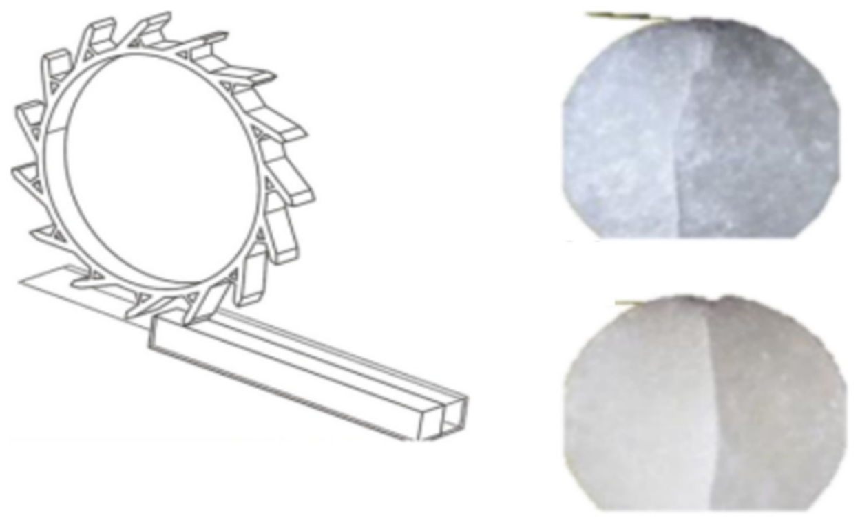
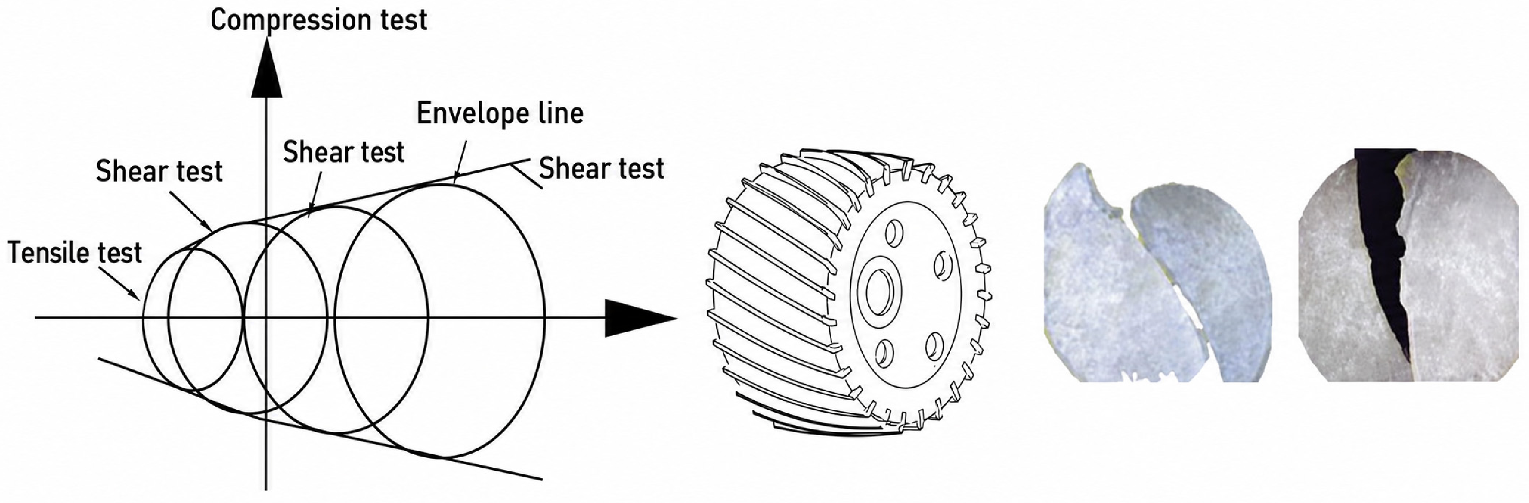
Rolling ice-breaking equipment primarily uses teeth mounted on a rotating drum to apply normal loads to compacted snow and ice, thereby generating localized stress concentrations. When the local stress exceeds the failure strength of the snow and ice layer, compressive cracking and fragmentation occur, followed by separation of the fractured layer from the pavement (
Figure 1). This type of equipment is particularly effective for highly compacted snow and ice. However, loads exerted by the drum teeth can be transmitted through the ice layer to the underlying pavement, creating a potential risk of pavement damage.
Li [
18], Yin [
19], and Wang [
20] numerically investigated the effects of tooth installation angle. Their results showed that excessively small installation angles produced insufficient ice-fracturing action. Installation angles of 50–55° provided a more favorable balance between ice-breaking capability and tooth loading, with a comparatively uniform load distribution at 55°. Tooth arrangement also governs the continuity of the fractured region. An excessively dense arrangement may repeatedly load the same area, whereas an overly sparse arrangement may leave unfractured zones. Tooth spacing should therefore balance fracture coverage against the effective contribution of each tooth.
In addition to tooth configuration, vibratory loading is an important determinant of rolling ice-breaking performance. Vibratory rolling superimposes a periodic dynamic load on the static load, thereby increasing the stress level within the ice layer. Experiments showed that, at a vibration amplitude of 4 mm, favorable ice-breaking performance could be achieved at both 10 and 15 Hz. At a given ice thickness, the force required under vibratory loading was markedly lower than that under static loading. A frequency of 10 Hz was more suitable for a 30 mm ice layer, whereas the preferred frequency increased to 15 Hz at an ice thickness of 40 mm. These results demonstrate that vibration frequency should be matched to ice-layer thickness.
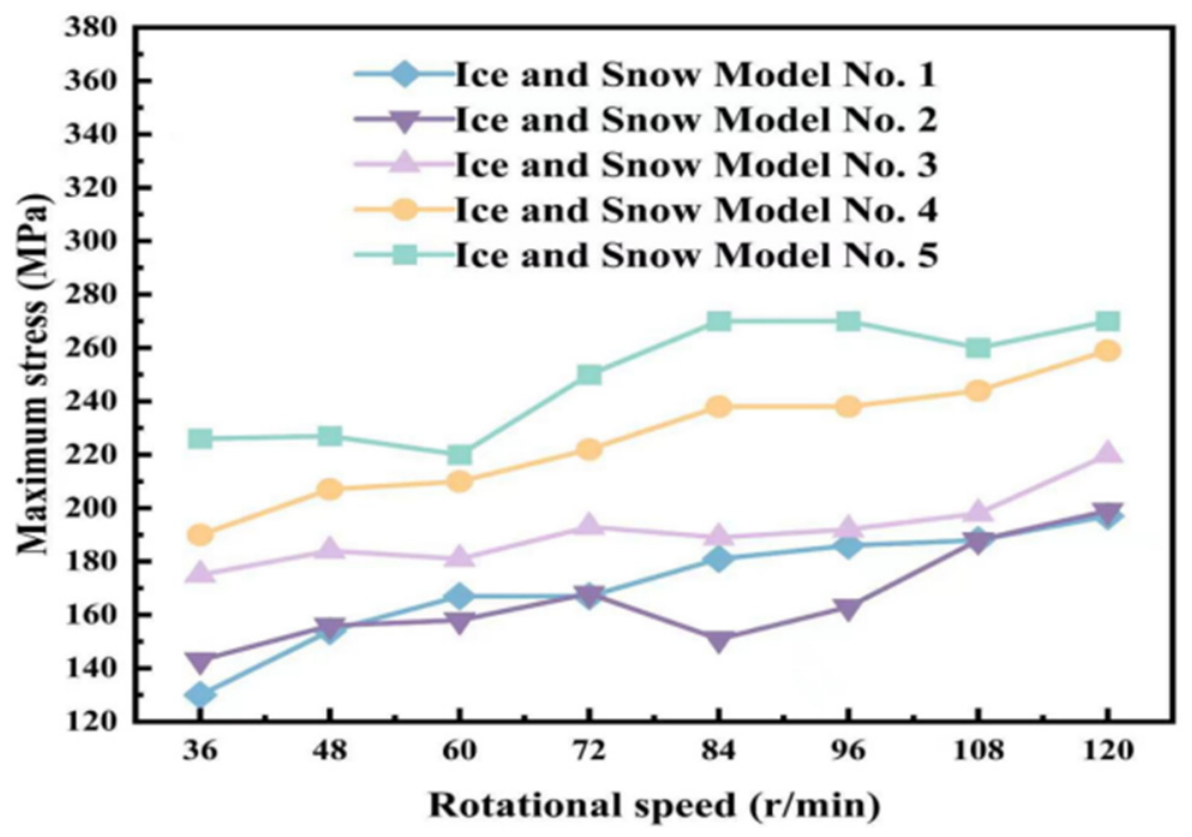
Drum rotational speed must likewise be adjusted according to the type and thickness of the snow and ice layer. Simulations reported by Han [
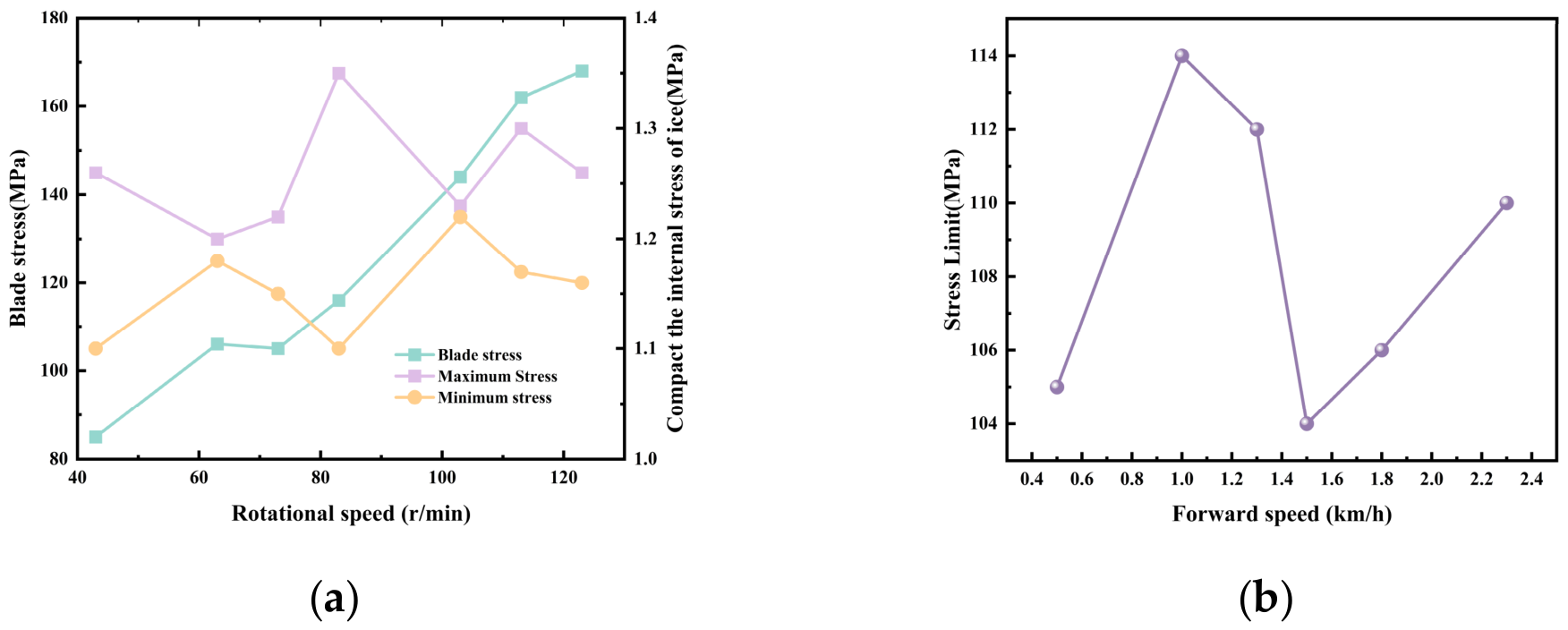
21] showed that, for a 30 mm thick snow and ice model, the recommended drum speed range decreased from 90–120 r/min for compacted snow to 30–60 r/min for compacted ice. This trend indicates that lower rotational speeds are required as snow and ice strength increases (
Figure 2). The Vicon roller ice-breaking system could treat ice layers approximately 50 mm thick at operating speeds of 5–15 km/h, demonstrating the capability of rolling equipment to process relatively thick ice. When the ice layer is thin, however, drum teeth are more likely to penetrate the layer and transmit load directly to the pavement [
22]. In practice, drum speed, tooth penetration depth, and normal load should therefore be adjusted according to snow and ice type and thickness to balance ice-breaking effectiveness with pavement protection.
Overall, the parameter ranges reported for rolling ice-breaking equipment have generally been derived from specific snow and ice models under limited operating conditions, and their transferability to variations in field ice thickness, mechanical strength, and interfacial bonding remains uncertain. Although increasing vibration intensity or tooth load can enhance ice-breaking capability, it may also accelerate tool wear and aggravate pavement damage. Future studies should therefore expand experimental validation across a broader range of temperatures, ice thicknesses, and compaction levels while incorporating ice-breaking efficiency, energy consumption, and pavement damage into a unified performance evaluation framework. Ice-condition sensing should also be integrated with adaptive regulation of vibration frequency and drum speed to improve operational adaptability and equipment reliability.
2.2. Rotary-Cutting Ice-Breaking Equipment
Rotary-cutting ice-breaking equipment uses rotating teeth to continuously penetrate compacted snow and ice, inducing localized shear deformation and stress concentration. When the induced stress exceeds the failure strength of the snow and ice layer, the material fractures into fragments or blocks and progressively separates from the pavement [
23]. Compared with rolling equipment, rotary-cutting systems generate localized failure through controlled cutting depth and tooth trajectory. Their performance is therefore highly sensitive to tooth geometry and to the matching of rotary-cutting speed with vehicle travel speed (
Figure 3).
Existing studies have focused primarily on optimizing tooth geometry and operating parameters. Cutting tests conducted by Wang [
24] showed that tooth installation angle had the strongest influence on cutting resistance. The preferred parameter combination comprised a cutting depth of 18 mm, an installation angle of 35°, and a clearance angle of 13–15°. Within the tested range, cutting resistance was approximately 2.5–7.8 kN.
Numerical results reported by Liu [
25] indicated that, for a 25 mm thick compacted snow and ice layer and a rotary-cutting drum speed of approximately 73.5 r/min, increasing travel speed from 0.5 to 2.3 km/h produced only minor changes in peak tooth stress. This result suggests that rotary-cutting speed has a stronger influence on tooth loading than travel speed (
Figure 4).
Prototype tests further clarified the operating applicability of rotary-cutting equipment. Zhao [
26] tested an approximately 40 mm thick compacted snow and ice layer and a 10 mm thick layer of artificially frozen pure ice, achieving removal rates above 95% in both cases. Wang [
24] further showed that steel brushes, concave discs, and toothed-wheel components were suitable for compacted snow and ice with densities below 500 kg/m
3 and thicknesses of 30–50 mm, whereas wedge-shaped components were more suitable for film-like compacted ice with densities above 500 kg/m
3. All four component types achieved removal rates exceeding 90%.
Overall, the operating parameters reported for rotary-cutting ice-breaking equipment have generally been derived from specific snow and ice specimens under limited test conditions, and their transferability to variations in ice thickness, density, and interfacial bonding remains uncertain. Increasing cutting depth or rotary-cutting speed may also increase tooth loading, energy consumption, and risk of pavement damage. Future studies should therefore cover a broader range of operating conditions and jointly evaluate removal rate, cutting resistance, energy consumption, and pavement damage. Rotary-cutting speed, travel speed, and cutting depth should then be adaptively regulated according to ice-layer conditions to maintain removal efficiency while minimizing pavement damage under complex roadway conditions.
2.3. Impact Ice-Breaking Equipment
Impact ice-breaking equipment applies periodic loads to the ice layer through rotating or oscillating hammer heads, generating localized stress concentrations. When the local stress exceeds the failure strength of the ice, cracking and spalling occur [
27]. This equipment is primarily suited to road sections requiring intensive ice-breaking, particularly those covered by thick, strongly bonded compacted snow and ice. It is generally less suitable for thin ice or for road sections with stringent pavement protection requirements.
Existing studies have focused mainly on hammer mounting configurations, impact parameters, and the coupled response of ice-layer fracture and pavement loading. To reduce impact load transmission and improve adaptability to pavement unevenness, Wang [
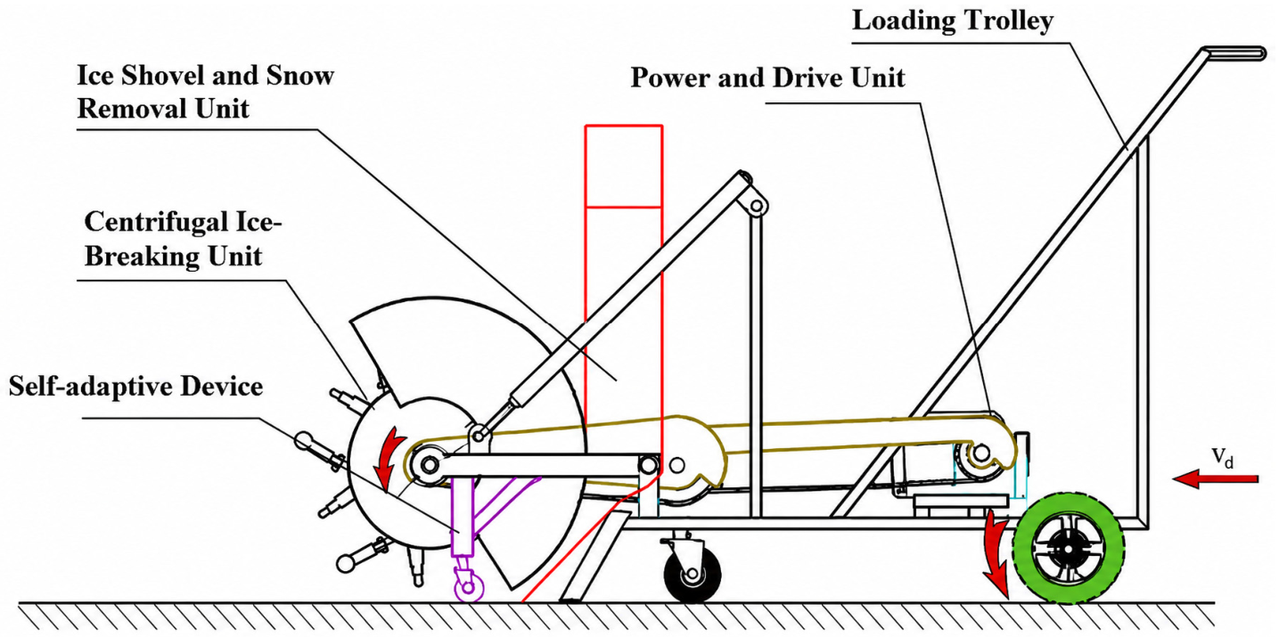
28] designed an ice-breaking system incorporating hinged centrifugal hammers and an elastic self-adaptive mechanism (
Figure 5). At −28 °C, with an ice-layer thickness of 20–35 mm and an average drum speed of 120 r/min, two to three consecutive hammer impacts were sufficient to fracture the local ice layer. The hinged-hammer configuration and elastic cushioning mechanism provide a structural basis for improving terrain adaptability and reducing impact transmission to the pavement.
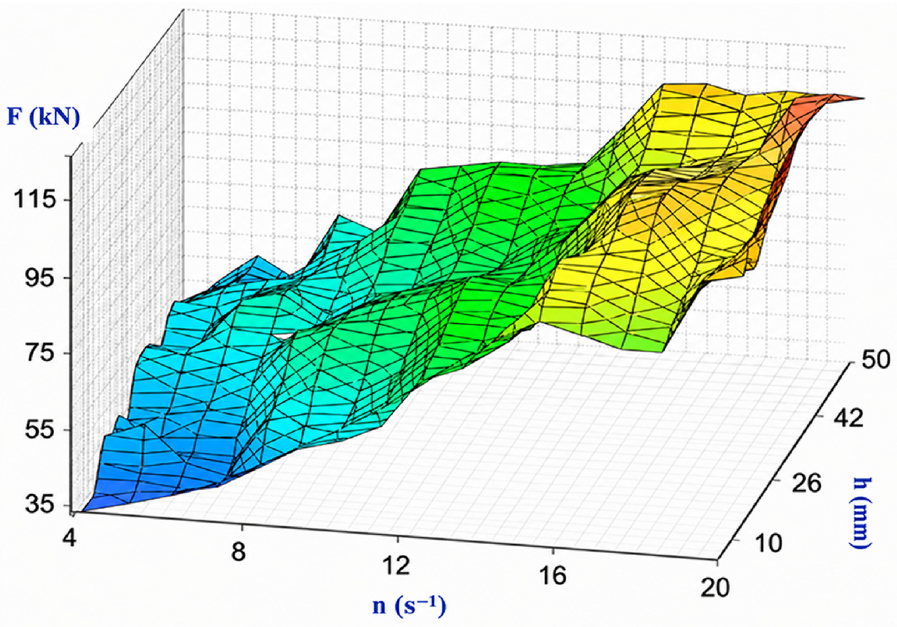
Doudkin et al. [
29] investigated the ice-breaking performance of flexibly connected spherical hammers using finite element analysis and road tests. Under the equipment configuration and operating conditions considered, the system could remove thin ice approximately 3 mm thick and process snow and ice cover up to approximately 15 cm thick in a single pass. The relative error between model predictions and experimental results ranged from 5% to 12%. As working shaft speed increased from 840 to 1200 r/min, the load margin relative to the asphalt-concrete failure threshold decreased from approximately 79.7% to 12.3%. Thus, although higher rotational speed intensifies the impact action, it also substantially reduces the pavement safety margin. Rotational speed should therefore be matched to ice-layer thickness, temperature, and pavement load-bearing capacity (
Figure 6).
To further quantify impact-induced ice fracture, Butin et al. [
30] conducted fundamental impact tests using a wedge-shaped indenter. At an initial velocity of 5.9 m/s, contact between the indenter and ice specimen lasted approximately 0.035–0.042 s. After impact, the fractured volume accounted for approximately 1% of the total specimen volume, whereas the damaged region covered approximately 11% of the upper ice surface. Across four tests, the average energy consumption per unit fractured volume was 2.67 kJ/dm
3. These results indicate that impact-induced damage is concentrated primarily near the indenter contact region and that energy consumption per unit fractured volume can serve as a quantitative indicator of impact energy utilization.
The operating parameters reported to date have generally been obtained from specific prototypes over limited ranges of ice conditions, and no parameter-matching method has yet been established that accounts for variations in ice-layer thickness, temperature, and interfacial bonding. Existing studies have also focused mainly on localized impact responses, while comprehensive evaluations of removal rate, specific energy consumption, pavement damage, and equipment vibration under continuous operation remain limited [
31]. Future research should strengthen investigations of hammer–ice–pavement coupling, integrate ice condition sensing with equipment vibration feedback, and develop adaptive regulation methods for rotational speed and operating height. A performance evaluation framework that simultaneously considers ice-breaking efficiency, energy consumption, and pavement safety should also be established.
2.4. Snowplow Equipment
Snowplow equipment removes snow primarily through blade penetration and guided lateral transport along the moldboard. During operation, vehicle tractive force is transmitted to the snow layer through the blade, subjecting the material to compression and shear. When the applied load exceeds the shear resistance of the snow and ice layer and the bond strength at the ice–pavement interface, the layer detaches and is displaced laterally along the moldboard [
32]. Snowplows are therefore most suitable for fresh snow, loose snow, and snow layers of moderate thickness, and they can also remove ice fragments produced by upstream ice-breaking operations. Highly compacted snow and strongly bonded ice generally require combined operation with an ice-breaking device [
33].
Existing studies have mainly addressed moldboard geometry, operating parameters, and operational safety. Tanaka [
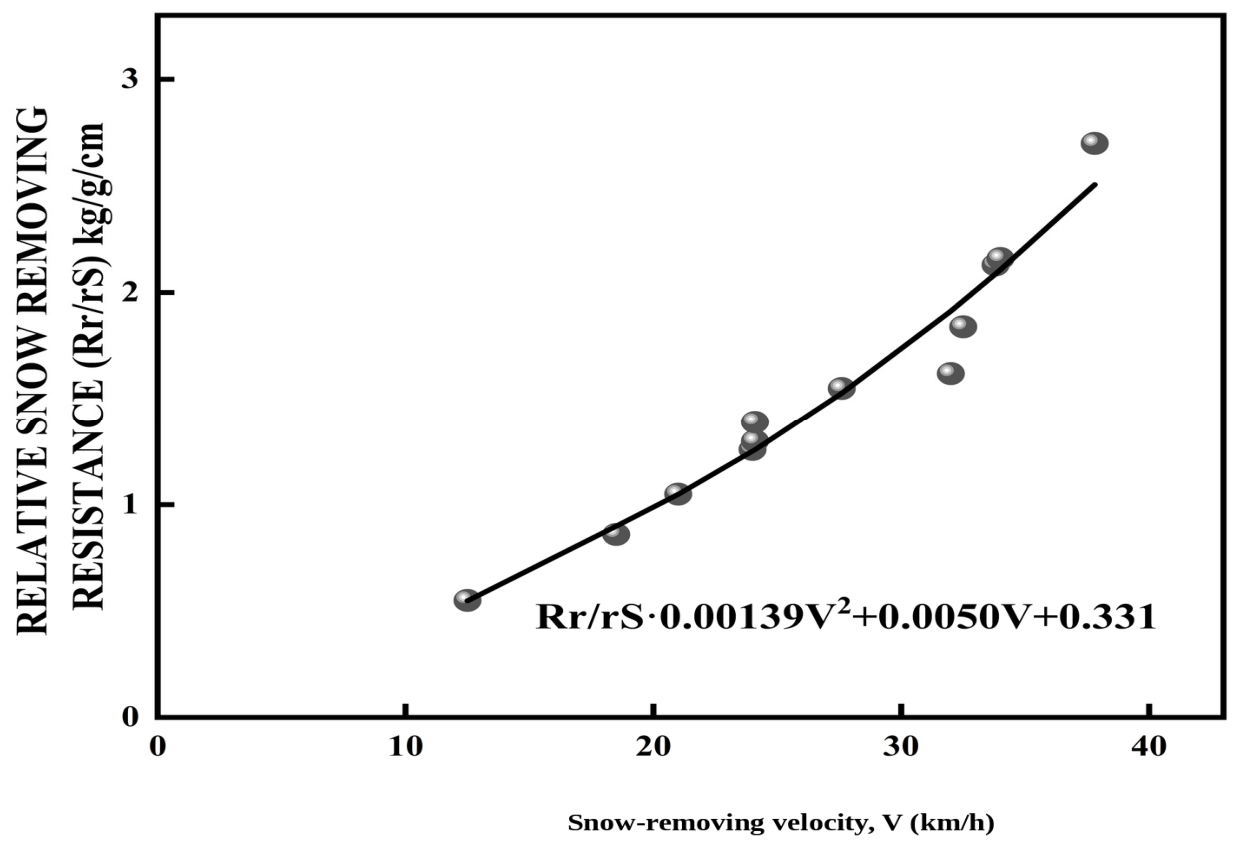
34] compared the field performance of snowplows with different moldboard surfaces in 5–20 cm of fresh snow. Moldboard geometry affected snow motion and removal resistance, and surfaces with more favorable snow flow characteristics exhibited lower resistance over the range of 12–40 km/h. A speed of approximately 12 km/h marked the transition from lateral displacement to continuous discharge along the moldboard. Snow acceleration resistance was proportional to the square of vehicle speed, whereas the required power was proportional to the cube of speed. Increasing vehicle speed can therefore promote snow discharge but at the cost of a marked increase in energy demand (
Figure 7).
Kong et al. [
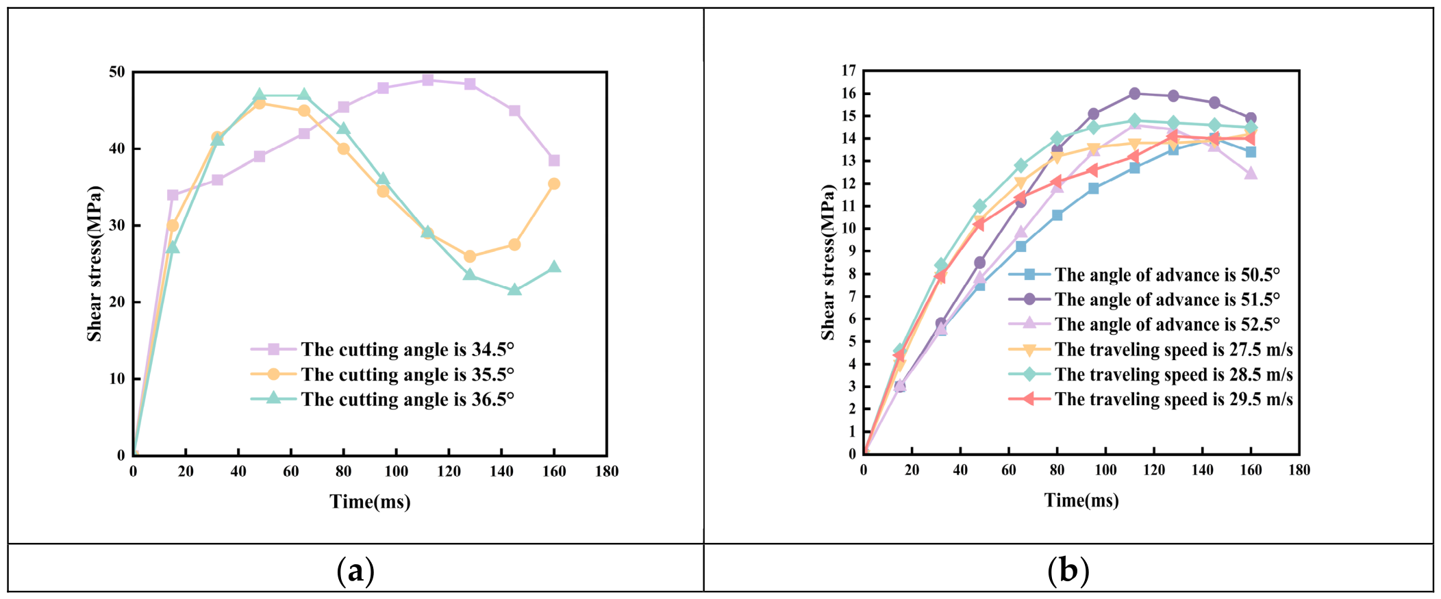
35] used LS-DYNA and ROCKY DEM to simulate cutting fracture and snow-throwing processes, respectively. The best overall performance was obtained at a cutting angle of approximately 36°, a travel angle of approximately 52°, and a prescribed speed of 28.5 m/s. Relative to the unoptimized design, snow-throwing height increased from 1.20 to 1.45 m and throwing distance from 10.21 to 12.60 m, corresponding to increases of approximately 20.8% and 23.4%, respectively.
Figure 8 presents the shear stress responses under different parameter combinations. Because blade–snow interaction is a short-duration transient process, the horizontal axis represents simulation time in milliseconds (ms), whereas the vertical axis represents shear stress in megapascals (MPa). These results demonstrate that coordinated parameter optimization can improve snow-throwing performance, although design optimization should not be based on clearance performance alone.
Prototype tests by Pell et al. [
36] showed that, at a blade–pavement angle of 45°, both axial and lateral forces at the vehicle–plow connection could be reduced by approximately 50%. In practice, however, operators often prefer a blade angle of approximately 80°, whereas an angle approaching 90° is more effective for scraping compacted snow and ice. Parameter selection must therefore balance structural loading against the ability to remove hard-packed snow and ice.
In addition to normal operating trade-offs, sudden collisions can directly compromise vehicle stability. Zhou et al. [
37] simulated the lateral dynamic response of a snowplow after impact with a hard ice block at an initial speed of approximately 40 km/h. A control strategy that increased rear-wheel lateral stability within 0.1 s after impact and raised the critical sideslip angle from 6° to 9° reduced both the time spent in the adjacent lane and the time required to regain stability by approximately 50%. With coordinated braking and steering control, the vehicle could remain on its original path. Obstacle-avoidance design should therefore mitigate local blade impacts while being integrated with whole-vehicle stability control.
Current snowplow systems still exhibit limited adaptability to complex snow conditions, difficulty balancing removal efficiency against energy consumption, and insufficient vehicle stability under sudden collision conditions [
38]. Some models assume continuous snow flow, uniform snow layers, and simplified friction and therefore cannot fully represent the compression, shear, and fracture of highly compacted snow during high-speed operation. In addition, reported metrics for snow removal resistance, throwing distance, and energy consumption vary among studies, limiting direct comparison. Future work should strengthen coupled mechanism research; use snow depth, compaction state, and obstacle recognition to adaptively regulate blade angle, ground pressure, and vehicle speed; and integrate cushioning and obstacle-avoidance structures with whole-vehicle stability control. A unified evaluation framework centered on removal rate, residual snow thickness, specific energy consumption, and pavement damage should also be established, while coordinated operation of snowplows with ice-breaking and rotary brush devices should be further developed.
2.5. Rotary Brush Snow Removal Equipment
Rotary brush snow removal equipment uses high-speed brush rotation to deflect the bristles during contact with the snow layer and pavement. Frictional forces and elastic recovery generate tangential loads that cause snow particles to slide, roll, and be ejected [
39]. Removal performance depends primarily on the bristle–pavement contact state; rotary brushes are therefore better suited to loose snow, thin residual snow, and residual snow and ice remaining after plowing. Conventional flexible brushes generally cannot fracture highly compacted snow and ice or strongly bonded ice layers effectively and therefore require steel-wire bristles or coordinated operation with ice-breaking and plowing devices [
40].
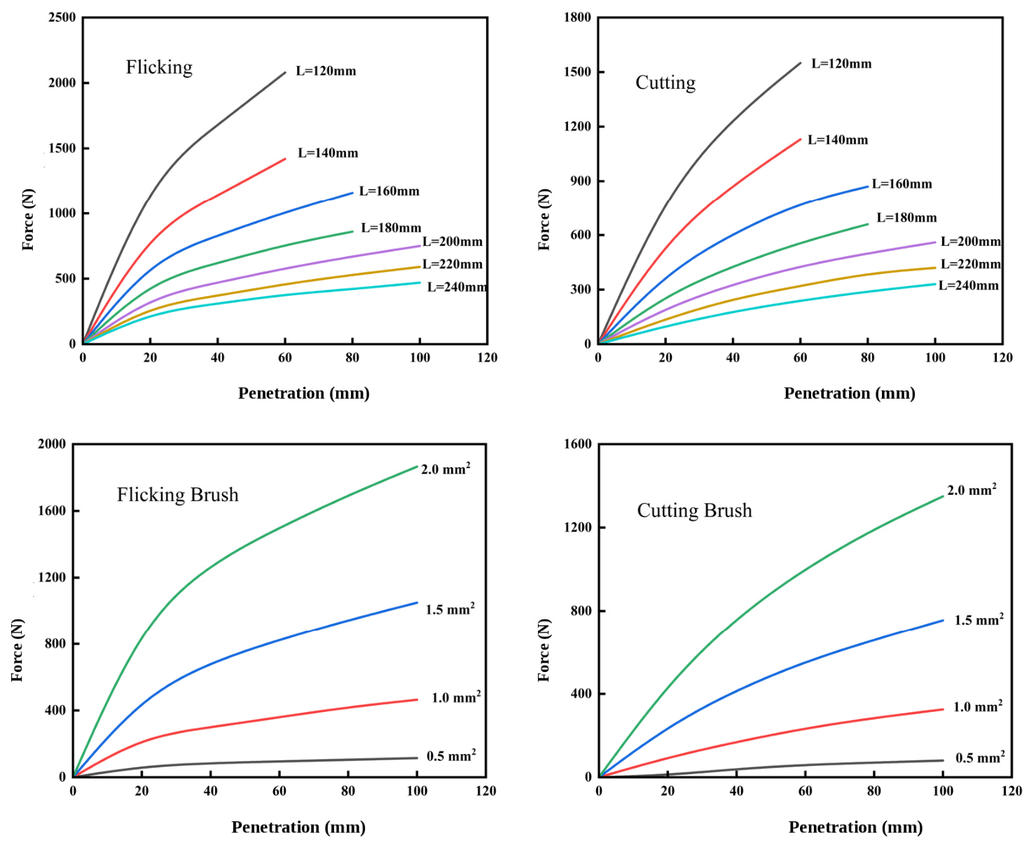
Existing studies have focused on bristle geometry, helical arrangement, kinematic parameter matching, and service reliability. Wahab et al. [
41] used three-dimensional finite element analysis to investigate steel-bristle contact loads under pavement constraint, tip friction, and centrifugal effects. At the same penetration depth, reducing bristle length from 240 to 120 mm increased the ground contact load by approximately fourfold. At a constant cross-sectional aspect ratio, increasing cross-sectional area from 1 to 2 mm
2 likewise increased the load on an individual bristle by approximately fourfold. Higher contact loads strengthen the action of the bristles on the snow and ice layer but may also accelerate bristle wear and increase impact loading on the pavement (
Figure 9).
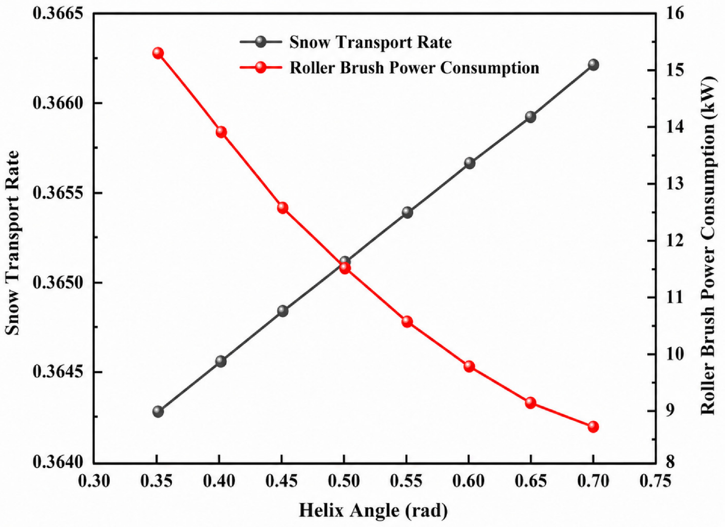
Helical arrangement and kinematic parameters primarily govern snow conveying and power consumption. Zhang [
42] established models for the snow-conveying volume and power consumption of a helical rotary brush. Increasing the helix angle from 0.35 to 0.70 rad increased snow-conveying volume by only approximately 0.52% while reducing rotary brush power consumption (
Figure 10). For a brush radius of 0.4275 m, bristle deformation of 0.03 m, and vehicle speed of 6.94 m/s, the corresponding matched rotational speed was 214.36 r/min. Excessive vehicle speed can result in insufficient axial snow conveying. Helix angle and brush speed should therefore be jointly matched to vehicle speed, bristle deformation, required snow-conveying capacity, and power consumption. Wang et al. [
43] further developed a load regression model from 2950 finite element cases and obtained a coefficient of determination of 0.9144 when evaluated against randomly selected finite element results. The model provides a basis for optimizing brush geometry and operating parameters.
Bristle wear is a key determinant of sustained operating performance. Kowalska et al. [
44] used microscopy, tensile testing, and hardness measurements and found that the mean tensile strength of used steel bristles decreased from 2387 to 2124 MPa, a reduction of approximately 11%, whereas tip microhardness increased from 606 to 650 HV0.1. Continuous friction and impact therefore lead to strength degradation and localized hardening. To improve wear resistance, Li et al. [
13] developed a semi-rigid, steel-wire-rope flexible deicing brush based on the brittle–ductile deformation and fracture characteristics of ice and applied epoxy resin impregnation. Wear tests conducted at different impregnation times and rotational speeds showed that 20 min of impregnation produced superior wear resistance (
Figure 11).
Although existing studies have addressed bristle geometry, kinematic parameters, and wear behavior, unified quantitative evaluations of removal rate, residual snow and ice ratio, and energy consumption across different snow thicknesses, densities, and adhesion states remain lacking. Bristles are also susceptible to wear and performance degradation under sustained low-temperature impact [
45]. Future studies should strengthen investigations of bristle–snow–pavement coupling, establish standardized methods for evaluating removal effectiveness and energy consumption, and use snow condition recognition to coordinate brush speed, penetration depth, and vehicle speed while improving durability under cyclic low-temperature loading.
The preceding studies demonstrate substantial differences among mechanical technologies in operating mechanisms, applicable snow and ice conditions, risk of pavement damage, and principal engineering limitations.
Table 1 summarizes the key characteristics and engineering applicability of representative mechanical ice-breaking and snow removal equipment.
Overall, mechanical ice-breaking and snow removal technologies differ primarily in load application mode, applicable snow and ice conditions, and risk of pavement damage. Rolling and impact equipment provide strong ice-fracturing capability and are more suitable for thick or strongly bonded compacted snow and ice, but their relatively high contact loads increase the risk of pavement damage. Rotary-cutting equipment produces localized shear fracture and offers greater control over cutting depth, although excessive penetration may increase cutter loading and risk of pavement damage. Snowplows and rotary brushes impose lower mechanical loads on the pavement and are therefore more suitable for loose snow and residual snow removal, but their ability to remove strongly bonded ice is limited. Consequently, mechanical technologies should be selected according to snow and ice thickness, compaction and bonding conditions, and pavement protection requirements. Their engineering effectiveness can be further improved through coordinated operation of ice-breaking, plowing, and rotary brush devices.
3. Research Progress in Thermal Deicing Equipment
Thermal deicing equipment applies externally supplied heat to iced surfaces, raising the temperature of the snow and ice layer or inducing phase-change melting. The resulting thermal action weakens bonding at the ice–pavement interface and promotes detachment. According to the mode of heat delivery and the dominant heating mechanism, thermal systems can be classified as hot-air, steam, microwave, and laser deicing equipment.
3.1. Hot-Air Deicing Equipment
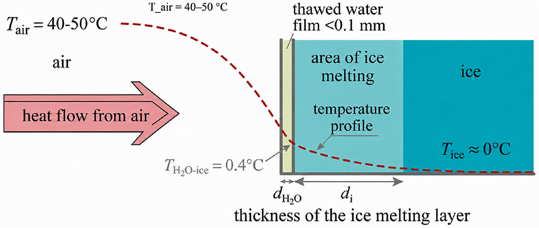
Hot-air deicing equipment directs high-temperature airflow onto the snow and ice surface and relies on convective heat transfer to raise the ice temperature and induce localized melting (
Figure 12). Heat is subsequently transferred toward the ice–pavement interface, where formation of a meltwater film reduces interfacial bond strength and facilitates detachment and subsequent removal [
46]. Because increasing ice thickness lengthens the heat-transfer path and intensifies environmental heat loss, hot-air systems are more suitable for thin ice, ice films, and residual snow and ice after mechanical treatment and have limited effectiveness when used alone on thick or strongly bonded ice [
47].
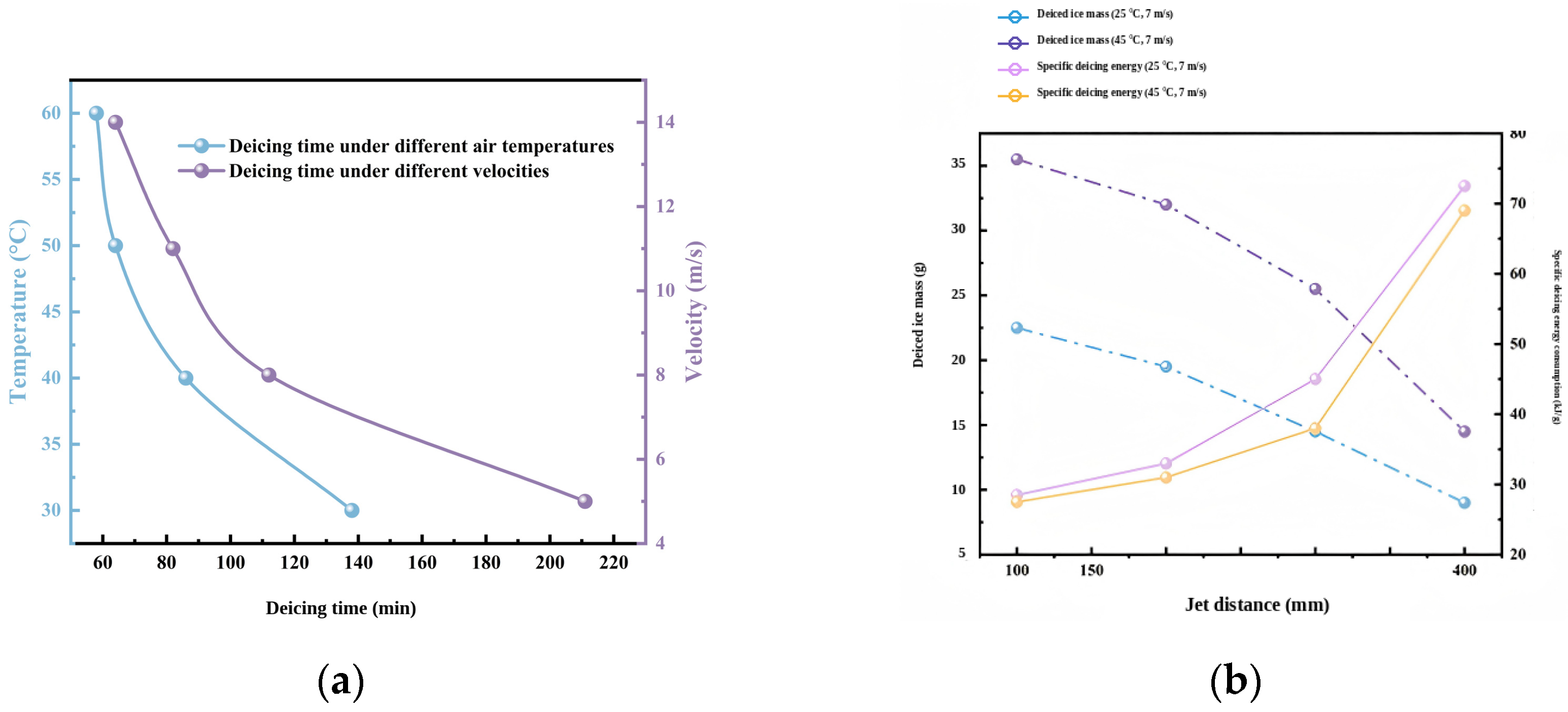
Hot-air temperature and velocity are the principal parameters governing melting efficiency and energy consumption. Xie et al. [
48] reported suitable ranges of 40–50 °C and 8–14 m/s, respectively (
Figure 13a). Increasing temperature from 50 to 60 °C reduced energy efficiency from 12.1% to 10.9%, whereas waste-heat recovery increased it from 8.8% to 12.1%. Further increases in hot-air temperature or velocity therefore provide diminishing improvements in deicing performance, while waste-heat recovery can substantially improve energy utilization.
Jet distance and outlet angle also influence melting performance [
49]. Chi et al. [
50] reported that increasing jet distance from 100 to 400 mm reduced the deiced ice mass by approximately 50% (
Figure 13b). Fluent simulations by Liu et al. [
51] showed that at 320 K and 1.5 m/s, melting required 8.4 s for a perpendicular jet but 13.3 s when the jet was inclined by 30° relative to the ice surface, an increase of approximately 58%. Jet distance and outlet direction should therefore be optimized jointly to limit jet diffusion and convective heat loss along the flow path.
Figure 13.
Effects of operating parameters on hot-air deicing performance: (
a) deicing histories under different hot-air temperatures (°C) and air velocities (m/s), with elapsed time expressed in minutes (min) [
48]; (
b) effects of jet distance (mm) on deiced ice mass (g) and specific deicing energy consumption (kJ/g) [
50].
Figure 13.
Effects of operating parameters on hot-air deicing performance: (
a) deicing histories under different hot-air temperatures (°C) and air velocities (m/s), with elapsed time expressed in minutes (min) [
48]; (
b) effects of jet distance (mm) on deiced ice mass (g) and specific deicing energy consumption (kJ/g) [
50].
Compared with mechanical ice-breaking equipment, hot-air deicing is non-contact and imposes less direct mechanical damage on the pavement. However, melting requires sustained heat input and is strongly affected by ice thickness and environmental heat losses [
52]. In one application involving the large and geometrically complex surface of a railway vehicle, deicing an entire train with hot air required approximately 8 h, illustrating the long treatment time and high energy demand associated with large-scale use. Future research should establish comparable experimental conditions and evaluation metrics, including treatment time per unit area, melting energy per unit mass, melting rate, and ice removal rate. Nozzle arrangement and hot-air delivery structures should be optimized, circulation and waste-heat recovery should be improved, and coordinated operation with mechanical ice-breaking devices should be further developed.
3.2. Steam Deicing Equipment
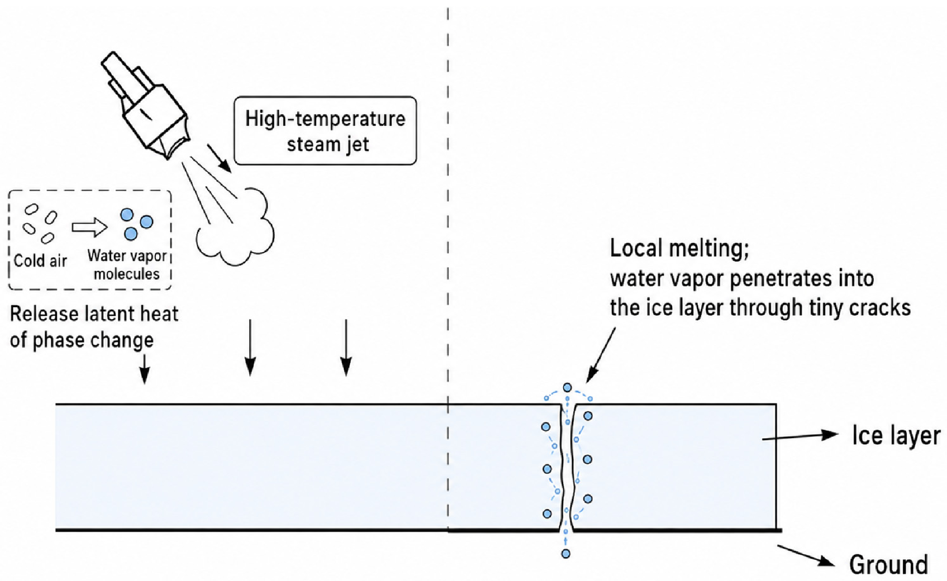
Steam deicing equipment directs high-temperature steam onto the snow and ice surface. Latent heat released during condensation rapidly raises the ice temperature and induces localized melting. Condensate and meltwater then penetrate cracks and the ice–pavement interface, weakening adhesion and facilitating detachment and subsequent removal (
Figure 14) [
53]. Compared with hot-air systems, which rely mainly on sensible heat, steam condensation provides higher local heat-transfer rates and is therefore more suitable for localized residual ice and thin ice layers approximately 10 mm thick or less [
54].
Research has focused mainly on steam-jet parameters, nozzle geometry, and combined operating modes. Xu et al. [
55] proposed a system that combines microwave preheating of the ice–pavement interface with high-pressure steam cutting. At a steam temperature of 413 K and a nozzle radius of 5 mm, the ice-hole radius increased from approximately 7 to 14 mm after 1 s of steam exposure. For a 5 mm thick ice layer, theoretical energy consumption was approximately 80% of that required for complete conventional melting, indicating that local steam cutting combined with interfacial preheating can reduce thermal energy demand.
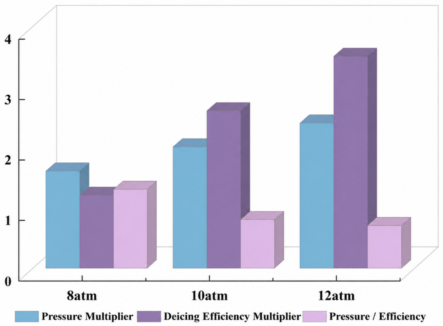
Steam pressure, jet angle, and operating distance directly determine the jet intensity delivered to the ice surface. Numerical studies by Lin [
56] and Hou [
57] showed that deicing efficiency increased as pressure rose from 8 to 12 atm, although the incremental benefit progressively diminished. A pressure of 12 atm provided a favorable balance between deicing performance and energy consumption (
Figure 15). For an 8 mm thick ice layer at −20 °C, a conical included angle of 15° and a length-to-diameter ratio of 1 yielded favorable melting performance. A subsequent orthogonal optimization of a multi-nozzle configuration identified an inlet diameter of 2 mm and an operating height of 15 mm as a preferred combination.
Nozzle geometry and arrangement also influence jet coverage and energy utilization. Xing [
58] compared nine orthogonal test schemes and found that operating height had the greatest influence on deicing efficiency, followed by nozzle arrangement and nozzle diameter. Huang [
59] optimized inlet diameter (1.5–2.5 mm), conical section length (2.5–3.5 mm), and length-to-diameter ratio (1–2), obtaining preferred values of 2 mm, 3 mm, and 2, respectively. Range analysis identified inlet diameter as the dominant factor, followed by the length-to-diameter ratio, whereas conical section length had the smallest effect.
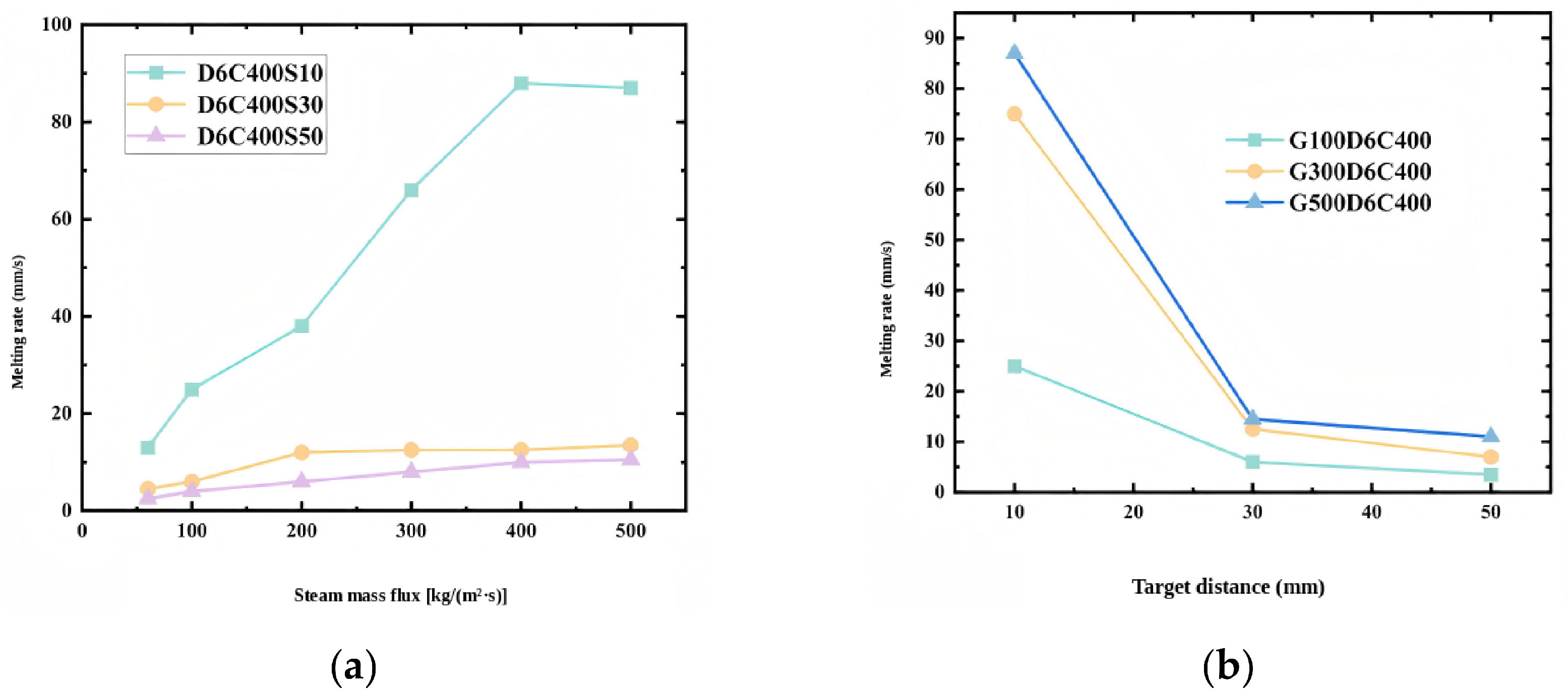
Submerged steam-jet tests by Cong [
60] showed that increasing steam mass flux from 60 to 500 kg/(m
2·s) increased the melting rate by approximately 5–10 times, whereas increasing target distance from 10 to 50 mm reduced the melting rate by approximately 90% (
Figure 16). Increasing nozzle diameter can also increase the melting rate but may reduce melting efficiency. By contrast, increasing steam mass flux and reducing target distance can improve both melting rate and energy utilization.
Overall, existing studies have focused primarily on steam-jet parameters and nozzle optimization, while performance under complex roadway conditions remains insufficiently validated. The combined effects of ice thickness, ambient temperature, and interacting process parameters have not been fully characterized, and current models still inadequately represent steam condensation, ice–water phase change, and multiphase flow. Meltwater accumulation may further reduce heat-transfer efficiency and increase the risk of refreezing. Future work should strengthen validation across different ice thicknesses and low-temperature conditions, improve coupled models of steam condensation and ice melting, optimize intermittent steam supply and meltwater removal, and promote coordinated operation with mechanical removal devices to improve energy utilization and continuous operation capability.
3.3. Microwave Deicing Equipment
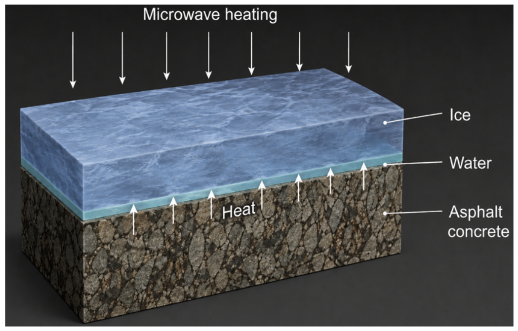
Microwave deicing exploits differences in dielectric loss characteristics between ice and pavement materials to generate preferential heating at the ice–pavement interface [
61]. Because ice absorbs microwave energy relatively weakly, microwaves can penetrate the ice layer and be preferentially absorbed by the pavement, where electromagnetic energy is converted into heat. The resulting temperature rise at the ice–pavement interface forms a meltwater layer, reduces interfacial bond strength, and promotes detachment (
Figure 17). This technology is particularly suitable for strongly bonded thin ice formed by freezing rain and for residual bonded ice remaining after mechanical treatment [
62].
Microwave frequency and the dielectric properties of pavement material are key factors governing interfacial heating. Through simulation and laboratory testing, Ding et al. [
61] and Wang et al. [
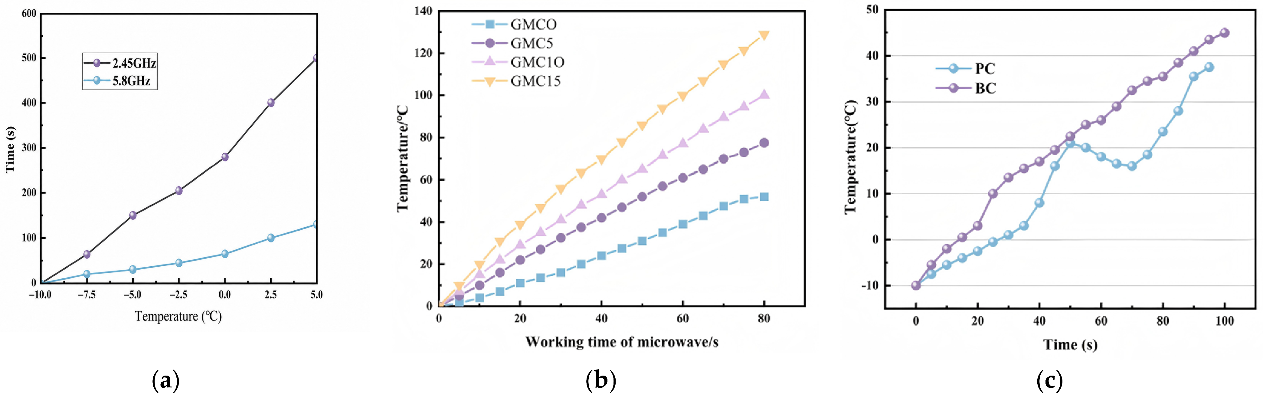
63] found that under identical input conditions, an asphalt-concrete ice–pavement interface required approximately 280 s to reach 0 °C at 2.45 GHz but only 65 s at 5.8 GHz. The corresponding melting efficiency at 5.8 GHz was therefore approximately 4.31 times that at 2.45 GHz (
Figure 18a). Frequency describes the oscillation rate of the electromagnetic field, whereas the microwave input level is expressed here as source output power (W). Increasing output power accelerates heating, but excessive power may reduce temperature uniformity and increase the risk of pavement overheating.
Because conventional pavement materials have limited microwave absorption, microwave-absorbing additives have been introduced to enhance energy absorption and heating. Lu et al. [
64] and Liu et al. [
65] improved concrete absorption using black iron oxide and graphite, respectively. Adding 10 wt% black iron oxide increased microwave deicing efficiency by approximately 1.8 times, whereas 15 wt% graphite increased the temperature rise rate and effective deicing area to 2.5 and 2.2 times those of ordinary concrete, respectively (
Figure 18b,c). Ning et al. [
66] further found that adding 2% carbon fibers with a length of 0.6 cm approximately doubled the temperature rise rate and increased the deicing area by approximately 20%. Because excessive additive contents may adversely affect mechanical performance and constructability, improvements in melting efficiency must be balanced against pavement durability.
Figure 18.
Heating and deicing performance under microwave irradiation: (
a) comparison of deicing time at microwave frequencies of 2.45 and 5.8 GHz [
61]; (
b) temperature rise histories of graphite-modified concrete with graphite contents of 0, 5, 10, and 15 wt%, denoted as GMC0, GMC5, GMC10, and GMC15, respectively [
65]; (
c) comparison between plain concrete (PC) and black-iron-oxide-modified concrete (BC) [
64]. GHz denotes gigahertz and wt% denotes mass percentage.
Figure 18.
Heating and deicing performance under microwave irradiation: (
a) comparison of deicing time at microwave frequencies of 2.45 and 5.8 GHz [
61]; (
b) temperature rise histories of graphite-modified concrete with graphite contents of 0, 5, 10, and 15 wt%, denoted as GMC0, GMC5, GMC10, and GMC15, respectively [
65]; (
c) comparison between plain concrete (PC) and black-iron-oxide-modified concrete (BC) [
64]. GHz denotes gigahertz and wt% denotes mass percentage.
In addition to material properties, microwave source configuration and operating conditions strongly affect deicing performance. Wang et al. [
67] noted that microwave power, operating frequency, and equipment travel speed govern energy input per unit area, penetration depth, and temperature distribution. Gao et al. [
68] found that reducing the initial temperature from −5 to −10 °C increased melting time by approximately 9.3–14.8%, while each additional 1 cm of ice thickness increased melting time by approximately 5.9–13.0%. Parameter optimization should therefore account for microwave source arrangement, vehicle speed, and ambient snow and ice conditions rather than relying solely on the maximum temperature rise observed in stationary specimens.
Microwave deicing enables selective interfacial heating, causes relatively little direct pavement damage, and can be readily integrated with mechanical removal. However, current research remains dominated by laboratory-scale tests and static heating, and energy utilization, temperature field uniformity, and actual melting efficiency during continuous vehicle motion are not yet sufficiently understood. Onboard power supply, microwave leakage protection, and operating costs also constrain large-scale engineering deployment. Future studies should investigate the coupled effects of ambient temperature, ice thickness, vehicle speed, and microwave parameters and integrate microwave heating with mechanical detachment and residual ice sweeping to improve continuous operation capability and engineering applicability.
3.4. Laser Deicing Equipment
Laser deicing equipment directs a laser beam onto an iced region to induce localized heating and melting. For high-irradiance pulsed lasers, the resulting temperature gradients and thermal stresses can also initiate cracking, reduce the structural integrity of ice, and facilitate subsequent mechanical removal [
69]. Laser deicing is non-contact, highly directional, and spatially controllable, making it particularly suitable for localized icing on transmission lines, insulators, and rail vehicle components.
Laser wavelength is a key parameter governing energy absorption depth and heat distribution. Through numerical simulation and experiments, Qi et al. [
70] found that the absorption lengths of 1.064 μm Nd:YAG and 10.6 μm CO
2 lasers in ice were approximately 20 mm and 10 μm, respectively. The former produced predominantly volumetric heating, whereas the latter acted mainly at the surface. Under identical conditions at a laser power of 500 W, a 24 mm spot diameter, and 100 s exposure, the volumetric melting rates were 463.51 and 438.08 mm
3/s, while the energy consumption per unit melted volume was 1.08 and 1.14 J/mm
3, respectively, indicating broadly comparable melting capability.
Initial ice temperature also influences deicing time and energy consumption. Yan et al. [
71] investigated tunnel icicles and found that reducing the initial temperature from −5 to −15 °C increased deicing time from 476 to 651 s and specific energy consumption from 1.45 to 1.98 J/mm
3, as summarized in
Table 2.
Scanning speed, focal position, and output power jointly influence crack formation and melting. Yang et al. [
72] reported that at a scanning speed of 10 mm/s, with the focal plane located on the ice surface and a laser irradiance of 4.6 × 10
7 W/cm
2, up to 16 cracks formed within the test region. Excessively low scanning speed permits greater heat diffusion and reduces temperature gradients, whereas excessively high scanning speed provides insufficient energy per unit area; both conditions suppress thermally induced cracking. Zhen et al. [
73] quantitatively compared CO
2 laser output powers of 20–60 W. Increasing laser power reduced the time required to reach a melting depth of approximately 100 mm from 78 to 42 s but decreased the maximum energy utilization efficiency from 81.5% to 54.6%. Laser power must therefore be selected to balance melting rate against energy efficiency.
Laser deicing provides non-contact, directional, and highly concentrated energy input and can treat localized icing on distant or geometrically complex surfaces. However, higher power may increase energy losses and the risk of thermal damage to the substrate. Existing studies have mainly used regularly shaped ice specimens under static conditions and therefore do not fully represent complex icing morphologies or long-distance dynamic operation. Future research should improve the matching of laser parameters to icing characteristics and substrate thermal response; enhance target positioning, dynamic focusing, and spot-stability control; and combine laser-induced melting or cracking with mechanical detachment to improve efficiency and engineering applicability.
The four thermal deicing technologies differ substantially in energy deposition location, heat-transfer pathway, and engineering applicability.
Table 3 provides a comparative summary of their principal characteristics.
Overall, thermal deicing technologies differ primarily in energy deposition location, heat-transfer intensity, and treatment scale. Hot-air and steam systems are comparatively simple and are suitable for thin ice and localized residual ice, but their efficiency decreases rapidly as ice thickness and environmental heat loss increase. Microwave deicing preferentially heats the pavement and ice–pavement interface and is therefore advantageous for weakening strongly bonded thin ice, although onboard power supply and leakage protection remain important constraints. Laser deicing provides highly localized and controllable energy input, but its limited treatment area and high equipment cost restrict continuous road-scale operation. Consequently, thermal technologies are generally better suited to interfacial weakening, localized treatment, or residual ice removal than to complete melting of thick roadway ice. Their engineering effectiveness can be enhanced by combining thermal weakening with subsequent mechanical detachment and sweeping.
4. Research Progress in Multifunctional Integrated Snow Removal Vehicles
Multifunctional integrated snow removal vehicles are integrated systems designed to operate under diverse and complex snow and ice conditions. A single-vehicle platform may combine ice breaking, plowing, rotary brushing, snow and ice conveying, and thermal melting. Rather than relying on a single removal mechanism, these systems coordinate multiple working devices to fracture, detach, convey, and remove snow and ice, thereby improving adaptability to loose snow, compacted snow, hardened accumulations, and pavement icing. Based on the functional combination employed, such vehicles can be classified as mechanically integrated systems or thermal–mechanical integrated systems.
4.1. Mechanically Integrated Snow Removal Vehicles
Mechanically integrated snow removal vehicles combine multiple mechanical devices on a common vehicle platform and use sequential operation to fracture, remove, and clean residual snow and ice. Existing systems mainly follow two configurations. One employs multiple functional blades or mechanical ice-breaking devices to fracture and scrape compacted snow and ice. The other integrates a snowplow, rotary brush, and air-blowing unit to sequentially displace bulk snow, sweep residual snow and ice, and remove fine snow particles.
Compared with single-device systems, mechanical integration can reduce the number of repeated passes, but overall performance still depends on the operating sequence and parameter matching among functional units. Nixon and Coffey [
74] noted that winter maintenance vehicles can be equipped with front plows, wing plows, underbody scrapers, or mechanical ice breakers according to road conditions, thereby improving adaptability to different snow and ice states.
For compacted snow and ice, multi-blade plows arrange blades with different functions sequentially along the direction of travel. The systems used in several U.S. states typically employ a front flexible blade to remove loose snow, a rear ice-breaking blade to penetrate compacted snow and ice, and a cleanup blade to remove residual material. Each blade set can be adjusted independently to accommodate pavement irregularities and changing snow and ice conditions [
75]. For thicker bonded layers, rolling mechanical ice breakers can be combined with snowplows: the ice breaker first fractures the layer, after which the plow removes the resulting fragments. Field applications indicate suitability for compacted snow and ice at least approximately 19 mm thick and recommend an operating speed of 24–27 km/h, although tooth–pavement contact must be carefully controlled when the layer is thin [
39].
Airport runway snow removal requires both high operating speed and high clearance quality, leading to the development of high-speed multitask equipment that integrates plowing, sweeping, and air blowing. A front plow first displaces most of the snow toward one side of the runway, a centrally mounted rotary brush then removes residual snow, and a rear blower uses high-speed airflow to clear fine particles. The FAA [
76] defines vehicles capable of all three operations as high-speed multitask equipment and specifies an operating speed of at least 48 km/h. Such integration reduces the need for repeated passes by separate single-function vehicles and is therefore well suited to large-area, time-constrained environments such as airport runways.
Tuominen et al. [
77] compared the Vammas PSB 5500-4, Aebi Schmidt CJS-DI, Øveraasen RS 600, and Boschung Jetbroom 10000. Their maximum operating speeds were 60–65 km/h, sweeping widths were 3.56–7.50 m, and maximum sweeping capacities were 2.14 × 10
5–4.88 × 10
5 m
2/h. The Øveraasen RS 600 achieved approximately 40–50% greater sweeping capacity than the Vammas and Boschung units. Operational data further showed that the sweeping and blowing systems consumed more energy than vehicle propulsion, with energy use varying according to snowfall conditions and operating intensity. Increasing airport snow removal capacity therefore requires coordinated optimization of working width, operating speed, and energy consumption (
Figure 19).
4.2. Thermal–Mechanical Integrated Snow Removal Vehicles
Thermal–mechanical integrated snow removal vehicles combine collection and conveying devices with an onboard thermal unit to melt removed snow and ice directly. Existing systems mainly adopt two configurations. One uses scrapers within a melting tank to distribute collected snow and maintain contact with a heating plate. The other uses a snow blower and conveying duct to feed snow into an onboard melting tank, where high-temperature air supplies the heat required for melting. Overall performance depends primarily on matching snow-conveying capacity with thermal melting capacity.
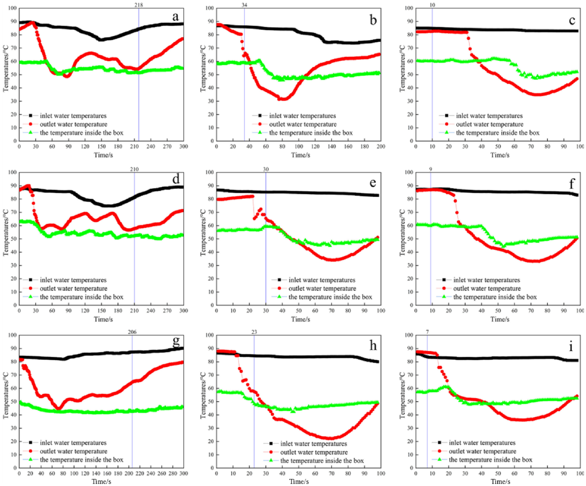
Li et al. [
78] designed an onboard melting system comprising an insulated tank, a heating plate, and a scraping device. Scraper rotation distributed snow more uniformly across the heating plate and reduced local bridging during melting. Increasing scraper speed from 0 to 42 r/min shortened the complete melting time to approximately 1/25 of its original value, whereas the heat-transfer fluid flow rate had a comparatively small effect (
Figure 20). Xu et al. [
79] subsequently incorporated an ice-fracturing blade and an intelligent control system, enabling agglomerated snow and ice to be broken after entering the melting region and allowing system power to be regulated according to snow and ice mass. Scraper speed exerted the strongest influence on melting time, and the proposed staged control strategy achieved a theoretical energy saving of 23.2%.
A mobile system consisting of a snow blower, conveying duct, and onboard melting tank has also been proposed. The front blower conveys snow through the duct into the melting tank, where high-temperature air provides the heat required for melting. A portion of the hot air is recirculated through the duct to reduce adhesion and blockage caused by refreezing. Although the design integrates collection, conveying, and melting, the patent documentation reports no experimental data on throughput or energy consumption, and actual operating performance remains to be verified.
Field operation of mobile snow melters also highlights the engineering limitations of thermal melting. Torick et al. [
80] evaluated the Snow Dragon SND900 and found that under the tested conditions, the cost of melting a unit volume of snow was USD 3.43/yd
3, higher than the USD 2.77/yd
3 required for mechanical loading and transport. Sand-contaminated snow also increased the frequency of sediment removal and disrupted continuous operation. Thermal–mechanical systems can therefore integrate snow removal with subsequent melting, but their practical deployment remains constrained by melting capacity, energy consumption, impurity handling, and operating cost.
4.3. Development Trends of Multifunctional Integrated Snow Removal Vehicles
As system integration increases, research is expanding from thermal–mechanical integration to environmental sensing, autonomous control, and digital management. Artificial intelligence and sensing technologies are increasingly being applied to road surface condition recognition and driver assistance; autonomous control methods are beginning to support driverless snow removal and multi-vehicle cooperation; and digital twin technologies are being used for road monitoring and operational management. Multifunctional integrated snow removal vehicles are therefore evolving from conventional functional integration to intelligent operating systems with perception, decision-making, and control capabilities [
81].
For environmental sensing and intelligent assistance, road images and meteorological data are used to characterize pavement snow and ice conditions, while infrared imaging, radar, and high-precision positioning support obstacle detection, vehicle guidance, and operating decisions under low-visibility conditions. These perception data can then be used to control working devices, enabling vehicles to select appropriate operating modes and adjust key parameters according to snow and ice coverage and equipment load [
82,
83].
Research on autonomous snow removal vehicles and cooperative operation has addressed anti-slip control on low-adhesion pavements, trajectory tracking, multi-vehicle formation, and winter maintenance route optimization [
84]. These methods can reduce dependence on driver experience and improve operational continuity over large areas such as airport runways and highways. Integrating vehicle motion control with snow removal resistance, working device load, and clearance quality can further improve autonomous operation under complex winter conditions [
80,
85,
86].
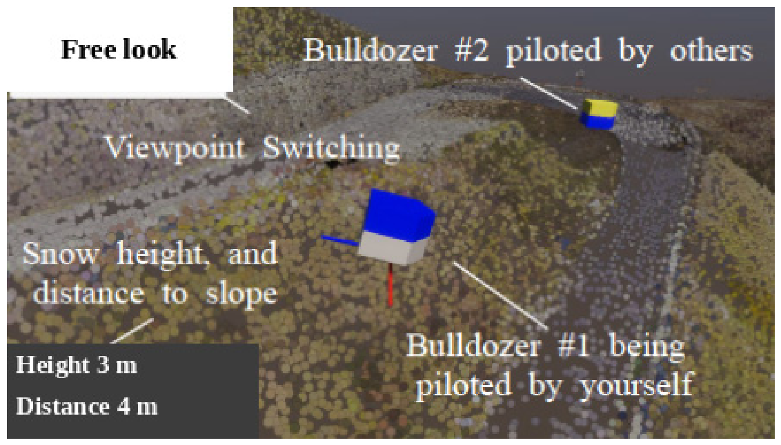
In digital twin-based decision support, vehicle position, road condition, and meteorological information have been integrated into digital platforms to support winter maintenance decision-making in deep-snow environments (
Figure 21). By mapping physical vehicles to corresponding virtual models, such platforms can centrally display operating status and road environment information and support planning and process monitoring. If equipment load, energy consumption, and clearance effectiveness are further incorporated, these platforms could evolve into full-process management systems covering planning, operational regulation, and performance evaluation [
87,
88].
Overall, these developments can improve adaptability to complex snow and ice conditions, reduce reliance on human judgment, and enhance operational safety and energy utilization. Existing research, however, remains focused primarily on road surface condition recognition, driver assistance, and maintenance management, with insufficient real-time integration between environmental perception, vehicle control, and ice-breaking, snow removal, and pavement-cleaning devices. Future work should strengthen information fusion across these subsystems and establish autonomous decision-making and closed-loop regulation based on real-time operating conditions, thereby advancing intelligent, autonomous, and cooperative multifunctional snow removal vehicles.
5. Conclusions and Outlook
This review evaluated mechanical ice-breaking and snow removal equipment, thermal deicing equipment, and multifunctional integrated snow removal vehicles with respect to operating mechanisms, key parameters, applicable conditions, and engineering limitations. The principal conclusions are as follows.
Mechanical equipment differs markedly in loading mode and applicable snow and ice conditions. Rolling equipment can process ice layers approximately 50 mm thick at 5–15 km/h, while rotary-cutting prototypes achieved removal rates above 95% for approximately 40 mm of compacted snow and ice and 10 mm of artificially frozen pure ice. Impact equipment can fracture 20–35 mm ice layers after two to three impacts, but increasing shaft speed from 840 to 1200 r/min reduced the pavement load margin from approximately 79.7% to 12.3%. Snowplows and rotary brushes are more effective for loose snow and residual material, whereas strongly bonded layers generally require combined mechanical treatment.
Thermal technologies enhance removal by melting ice or weakening the ice–pavement bond, but their performance is strongly condition-dependent. For hot-air deicing, suitable operating ranges of 40–50 °C and 8–14 m/s were reported, while increasing jet distance from 100 to 400 mm reduced the deiced ice mass by approximately 50%. Steam tests showed that increasing mass flux from 60 to 500 kg/(m2·s) increased the melting rate by approximately 5–10 times, whereas increasing target distance from 10 to 50 mm reduced it by approximately 90%. Microwave heating at 5.8 GHz reduced the time required for the interface to reach 0 °C from approximately 280 to 65 s relative to 2.45 GHz, while laser deicing exhibited a trade-off between melting rate and energy utilization efficiency.
Although numerous optimized values have been reported for tooth angle, drum speed, impact parameters, jet conditions, microwave frequency, and brush geometry, direct comparison remains difficult because snow and ice type, temperature, thickness, interfacial bonding state, and performance metrics vary substantially among studies. A unified evaluation framework should include, at minimum, removal rate, residual snow or ice thickness, operating speed, specific energy consumption, pavement damage, and equipment vibration, with all quantities reported together with clearly defined units and test conditions.
Multifunctional integrated snow removal vehicles can combine ice breaking, plowing, rotary brushing, conveying, and thermal melting on a single platform. Airport plow–sweeper–blower systems have reported operating speeds of 60–65 km/h, working widths of 3.56–7.50 m, and maximum sweeping capacities of 2.14 × 10⁵–4.88 × 10⁵ m2/h. In an onboard thermal snow-melting system, increasing scraper speed from 0 to 42 r/min reduced the complete melting time to approximately 1/25 of its initial value. These results demonstrate that overall system performance depends on functional sequencing, parameter matching, power allocation, and coordinated control rather than on the isolated performance of any single device.
Future research should establish a unified performance evaluation framework for representative roadway snow and ice conditions; strengthen real-time sensing of snow and ice states, operating loads, and residual snow and ice; and adaptively regulate tool speed, penetration depth, impact frequency, brush penetration, and heat source power according to operating conditions. Multi-device parameter matching and whole-vehicle coordinated control should also be investigated to improve removal efficiency, environmental adaptability, and pavement safety.