Article

Influence of Controlled Fiber Orientation on the Mechanical and Microstructural Properties of Cellulose Excelsior–Cement Composites


Department of Civil and Environmental Engineering, University of Maine, Orono, ME 04469, USA
*
Author to whom correspondence should be addressed.
Appl. Sci. 2026, 16(17), 8416; https://doi.org/10.3390/app16178416
Submission received: 10 June 2026 / Revised: 19 August 2026 / Accepted: 20 August 2026 / Published: 24 August 2026
(This article belongs to the Special Issue Innovative Building Materials: Design, Properties and Applications)

Abstract

This study investigates the influence of controlled fiber orientation on the mechanical and microstructural properties of cellulose excelsior fiber cementitious composites with an excelsior content of 75% by volume. Two different sets of composites were fabricated. In one set, no effort was made to orient the fibers, while in the other set fibers were preferentially aligned through manual placement and compressive consolidation. The mechanical performance, including elastic modulus and flexural strength, was evaluated. The internal structure, specifically porosity and 3D fiber orientation, was quantified using X-ray Computed Tomography (XCT) and subsequent 3D image analysis. The results demonstrate that the composites with aligned fibers exhibited a 20% higher bulk density and a significantly lower porosity (5.1%) compared to the non-aligned composites (9.0%), representing a 43% reduction in void volume. Further image analysis showed distinct differences in fiber orientation relative to the axis of the specimen. These different distributions led to a 120% increase in elastic modulus and a 58% increase in flexural strength. These results demonstrate how, within limits, the mechanical properties of the composite system can be controlled to meet application demands.

1. Introduction

Cellulose excelsior, sometimes referred to as wood wool, is wood product that has been used for a variety of applications ranging from packaging to the basis of a fiber-reinforced composite. It is an effective reinforcement for cementitious matrices due to its morphology, surface chemistry, and dispersion that influence matrix densification, crack bridging, and stress transfer. Across many studies, adding cellulose in macro- to nano-scale forms has been shown to improve tensile, flexural, and even compressive responses of cement composites when fiber content, aspect ratio, and interfacial properties are optimized. Early comparative work reported favorable mechanical balances versus common synthetic fibers, noting that cellulose can raise flexural strength and toughness while contributing to durability metrics such as impermeability and frost resistance through enhanced fiber–matrix bonding and refined pore structure [1,2,3]. Cellulosic fibers can induce internal curing effects by regulating moisture availability, which may initially delay hydration but ultimately promote denser microstructures and improved long-term strength [4]. Recycled or waste-derived cellulose can provide similar benefits when fibers are properly cleaned and well dispersed, while also supporting sustainability goals [5].
The microstructure–property linkage is central to these gains. Repeated wet/dry cycling studies show that cellulose contributes to more resilient microstructures with reduced microcracking and better retention of properties, provided the fiber network remains stable in alkaline pore solutions [6]. Chemical surface treatments that introduce urethane linkages or other compatibilizing chemistries improve the interfacial transition zone (ITZ), mitigating fiber debonding and alkalinity-driven degradation [7]. At the microscale, nanoindentation across the ITZ reveals that stronger local bonding correlates with higher effective modulus and tensile capacity at the composite scale [8]. In addition, Fiber geometry matters as well: diameter, aspect ratio, and morphology modulate pull-out, bridging, and network formation, influencing both peak load and post-peak ductility [9]. In alkaline environments, untreated cellulose can undergo depolymerization or swelling; therefore, durability strategies typically combine prudent fiber dosages, pH-resistant surface treatments, and matrix modifications, such as supplementary cementitious materials or alternative binders, to curb degradation [10].
Nanoscale cellulose forms, including cellulose nanocrystals (CNCs) and cellulose nanofibrils (CNFs), further expand the mechanisms available for performance enhancement by altering hydration kinetics, refining pore structure, and reducing permeability, thereby improving early-age rheology management and long-term durability simultaneously [11]. Nevertheless, dosage windows are narrow: excessive cellulose (especially fines) can scavenge water, disrupt packing, or hinder hydration, reducing strength—underscoring the need for optimized contents and mixing procedures tailored to fiber size and surface state [12]. Source-dependent traits also matter; for instance, bamboo-derived CNCs exhibit aspect ratios and surface functionalities favorable for reinforcing ordinary Portland cement matrices when adequately dispersed [13].
From a sustainability perspective, cellulose’s renewability and its availability from agricultural and industrial waste streams make it attractive for lowering embodied impacts of cementitious materials. Reviews repeatedly document the potential for emissions reduction when waste cellulose replaces more energy-intensive constituents or enables cement reduction through performance-driven mix optimization [5,14]. These same biogenic sources can be processed to yield mechanically robust, well-bonded fibers capable of bridging microcracks and slowing damage evolution, linking environmental advantages with structural performance.
Broader cellulose mechanics research helps explain why these behaviors translate into cement composites, as pre-cross-linked cellulose can self-assemble into tough networks with sacrificial bonds that dissipate energy under load, thereby illuminating the mesoscale network effects behind the crack-bridging and pull-out phenomena observed in cement systems [15]. Mechanical stretching realigns fibrils and increases tensile capacity, echoing the role of orientation and aspect ratio in determining composite response [16]. In paper and polymer matrices, CNF additions markedly improve tensile properties by promoting efficient stress transfer through hierarchical fiber networks [17]. At the crystal scale, native cellulose exhibits high moduli (reported up to ~143 GPa), indicating a strong upper bound for reinforcing potential when interfacial compatibility and load transfer are achieved [18]. All-cellulose composites prepared via controlled dissolution/regeneration show how dense, coherent networks can deliver high strength and flexibility, concepts translatable to cementitious systems if the ITZ (Interfacial Transition Zone) can be similarly engineered [19].
Moisture, on the other hand, interacts strongly with cellulose mechanics: lower moisture contents typically increase stiffness, while higher moisture levels plasticize the matrix and soften the fiber network [20]. For cement composites, this sensitivity motivates careful curing protocols and mixture water control so that the benefits of internal curing do not tip into over-softening or interfacial degradation. Parallel developments in cellulose hydrogels demonstrate how dual cross-linking strategies deliver exceptional toughness without sacrificing elasticity, offering design cues for tailoring fiber surfaces and binders to maintain ductility under cyclic or thermal loads [21]. Likewise, polymer–cellulose blends (e.g., PVA/cellulose) exhibit humidity-responsive stiffening and improved tensile properties as cellulose content rises, reinforcing the importance of interfacial compatibility in hybrid matrices [22]. Incorporating nanofillers such as graphene oxide with cellulose can yield ultra-low gas permeability and increased mechanical performance, hinting at multi-phase hybrid strategies (e.g., cellulose + 2D nanomaterials) to densify pore structures, curb transport, and raise strength in cementitious systems [23]. TEMPO-mediated oxidation facilitates more uniform, shorter nanofibrils with tunable surface charge, improving dispersion and interfacial interactions—properties valuable for cementitious mixing and ITZ enhancement [24].
Application-focused studies in cement systems demonstrate that the benefits of cellulose-based materials depend strongly on fiber scale, processing quality, dispersion, and matrix compatibility. At the microscale, mechanically processed cellulose fibers incorporated into ionomer or cementitious matrices can improve strength when processing produces clean fiber surfaces, controllable aspect ratios, and uniform dispersion [25]. At the nanoscale, nano fibrillated cellulose, cellulose nanocrystals (CNCs), and bacterial nanocellulose have been shown to enhance strength and durability by improving hydration control, refining pore structure, and limiting permeability, provided that dosages are optimized and agglomeration is minimized during mixing [26,27,28]. In lightweight and plastering cement materials, cellulose can also reduce density while maintaining workable strength and toughness, thereby lowering transport and installation demands [29,30]. In addition, waste cellulose recovered from multilayer packaging streams has been successfully compatibilized as reinforcement, creating circular-economy pathways that combine waste reduction with mechanical performance gains [31]. Collectively, these studies indicate that cellulose reinforcement is most effective when material selection, dosage, dispersion, and matrix interaction are considered together, which directly supports the focus of the present study on optimizing cellulose-based reinforcement in cementitious composites.
Building on these broad insights, recent research has emphasized not only the intrinsic reinforcing role of cellulose but also the importance of fiber alignment and quantification in determining composite performance. The alignment of cellulose fibers within cementitious composites is a critical parameter governing mechanical behavior, as fibers oriented parallel to the load direction enable efficient stress transfer and significantly improve tensile and flexural strength [32,33]. Fiber orientation can be tailored through stretching and drawing processes, and repeated stretching steps have been shown to increase nanofiber alignment, thereby improving stiffness and fracture resistance [34,35]. Also, all-cellulose composites with controlled nanofibril alignment achieve tensile strengths above 300 MPa and moduli near 14 GPa [36,37]. Similarly, hierarchical structures in wood-derived cellulose confirm that adjusting microfibrillar angle and orientation can tailor anisotropy and optimize mechanical properties [36].
While alignment at the micro- and nanoscale has been widely studied, translating these insights into cement-based systems requires examining how cellulose excelsior and wood fibers interact with cement matrices at the structural scale, particularly in wood–cement composites, a unique class of materials that combine wood fibers with cement paste and exhibit notable mechanical properties, including compressive strength, flexural strength, and elasticity.
The compressive strength of these composites can vary based on the wood-to-cement ratio, with some studies indicating optimal ratios yielding compressive strengths typically ranging from 5 to 10 MPa [38,39]. Specifically, one study reported compressive strengths of around 5 MPa for non-treated particles and approximately 10 MPa for treated particles [38]. Flexural strength has been linked closely to the geometry of wood particles, with certain configurations yielding strengths in the range of 4 to 7 MPa [39,40]. The modulus of elasticity (MOE) for these composites often aligns with values typical of low-density construction materials [41,42].
The alignment and direction of wood fibers, also, significantly influence the performance characteristics of the composites. Optimal fiber orientation can enhance load-bearing capacity and improve tensile strength, attributed to effective stress transfer mechanisms within the composite structure [43]. Variations in wood species and processing methods, including treatments and particle size, further modulate these properties, demonstrating the complex interplay between material composition and mechanical performance [44,45,46,47]. These observations reinforce that both intrinsic fiber orientation and bulk composite parameters determine overall performance. Since, fiber alignment and dispersion strongly dictate mechanical outcomes, reliable characterization methods are essential to capture three-dimensional fiber architecture and link it directly to strength and durability metrics.
Because these mechanical properties are so dependent on fiber orientation, advanced characterization methods are needed to capture how fibers are distributed within the cement matrix and how that distribution links to performance. X-ray computed tomography (CT), including laboratory μCT and synchrotron XCT, has become a standard non-destructive technique to capture three-dimensional fiber architecture and porosity [48,49]. CT has been applied to measure fiber orientation distributions in composites [50], assess local fiber alignment in large parts through region-of-interest scanning [51], and quantify orientation distributions using advanced microtomography [52]. Dual-energy CT has further improved void detection and pore characterization [53], while holotomography and synchrotron XCT have revealed multi-scale porosity such as node–bond pores in fiber-reinforced composites [54]. In concrete systems, XCT has demonstrated how fiber dispersion and distribution affect toughness and durability, confirming that microstructural alignment is directly linked to mechanical performance [55].
Together, these findings demonstrate that cellulose excelsior improves cementitious composites not only through densification, hydration control, and interfacial reinforcement, but also through the anisotropy created by fiber alignment. By integrating orientation-control strategies with CT-based imaging, researchers can both optimize composite performance and reliably quantify microstructural features—bridging the gap between sustainability, structural reliability, and advanced materials design.
After reviewing prior works, it is clear that cellulose-based reinforcement can enhance cementitious matrices through hydration control, pore refinement, and interfacial strengthening; however, a critical gap remains: few studies quantitatively link the 3D fiber architecture (orientation and porosity at high fiber volume) to the macroscopic mechanical response, and validated methods for deliberately aligning cellulose excelsior within cement at practical scales are sparse. To address this gap, we will: (1) develop a reproducible fabrication route to produce high-fiber-volume (75% by vol.) CE–cement composites with either random or intentionally aligned architectures via manual placement and compressive consolidation; (2) quantify the internal structure using high-resolution XCT and an Avizo workflow (segmentation, pore metrics, and structure-tensor-based orientation analysis); (3) measure elastic modulus (dual-LVDT direct strain) and flexural strength (three-point bending); and (4) establish a quantitative structure–property relationship that links orientation and porosity to stiffness and strength. In doing so, this paper provides both a practical alignment method and a validated imaging/analysis pipeline to translate microstructural engineering into predictable performance gains in CE–cement composites.
This work differs from prior cellulose–cement studies by (i) achieving very high fiber volume (75% by vol.) with a reproducible uniaxial alignment method; (ii) quantifying 3D fiber architecture (orientation + porosity) via XCT/Avizo with a structure-tensor pipeline; and (iii) establishing a direct structure–property relationship linking orientation/porosity to elastic modulus and flexural strength. Collectively, these advances close the gap between qualitative alignment claims and quantitative, mechanics-relevant microstructure in cellulose excelsior cement composites.

2. Materials and Methods

2.1. Materials and Constituent Characterization

The cementitious composites in this study were fabricated using three primary materials. The binder was a Portland Limestone Cement (PLC). All mixtures were prepared using standard tap water. The reinforcement consisted of cellulose excelsior (CE), a natural, untreated wood fiber.
To ensure accurate and repeatable mix proportioning, the physical properties of the CE were characterized. The density of oven-dry fibers was determined to be 420 kg/m3, and the fibers had an approximate length of 1.5 in. (38 mm). A critical step to maintain the designed water-to-cement ratio (w/c) was to bring the fibers to a Saturated Surface-Dry (SSD) condition. This was achieved by soaking the CE in water for 24 h to ensure full saturation, followed by placing the fibers in a centrifuge to remove all free surface water while retaining absorbed water. The moisture absorption in the SSD state was measured to be 115% by mass, and the corresponding bulk density of the SSD fibers was 980 kg/m3. The densities of all constituent materials are summarized in Table 1, and chemical ingredients of PLC in Table 2.

2.2. Mix Proportions and Specimen Fabrication

A high CE volume fraction of 75% was selected to represent a lightweight, high-fiber-volume composite system in which the effect of fiber architecture is expected to be pronounced. The objective of this study was not to optimize CE dosage, but to compare random and aligned fiber architectures at a fixed high fiber content and constant w/c ratio. The cement paste used for all mixtures maintained a constant water-to-cement (w/c) ratio of 0.4 by mass. Two specimen sets were produced: one with randomly oriented fibers (RND) and one with preferentially aligned fibers (ALG).
The fabrication procedure was as follows. First, the CE fibers were prepared to the SSD condition. The PLC and water were mixed separately to form a uniform paste. The SSD fibers and fresh cement paste were then combined in a large mechanical mixer until a uniform consistency was achieved. To meet the desired volume fractions, one kilogram of composite required 600 g of cellulose excelsior and 400 g cement paste, which in turn was made up of 286 g cement and 114 g of water. Batch sizes varied depending on the number of specimens being prepared.
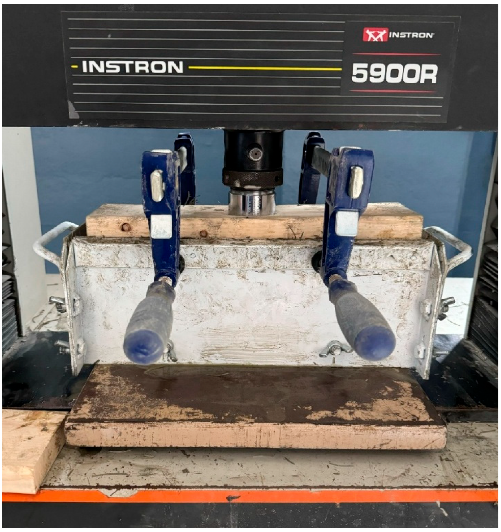
The fresh composite was cast into 14 × 4 × 4-inch steel molds. For the non-oriented (RND) specimens, the composite was placed in three layers, with each layer manually compacted to encourage an isotropic fiber distribution. For the aligned (ALG) specimens, the composite was carefully laid into the mold to orient the long axis of the fibers parallel to the longest dimension of the mold. After filling, an oiled wooden lid was placed on the mold, and the assembly was placed in an Instron 5900R universal testing machine, which was used as a hydraulic press (Figure 1). A sustained compressive pressure of approximately 110–120 psi was applied to the 75% CE mixture to consolidate the sample, expel entrapped air, and enhance fiber-matrix contact. The same consolidation range was used for both groups so that the main intended difference between the specimens was the fiber placement procedure.

2.3. Curing and Final Sample Preparation

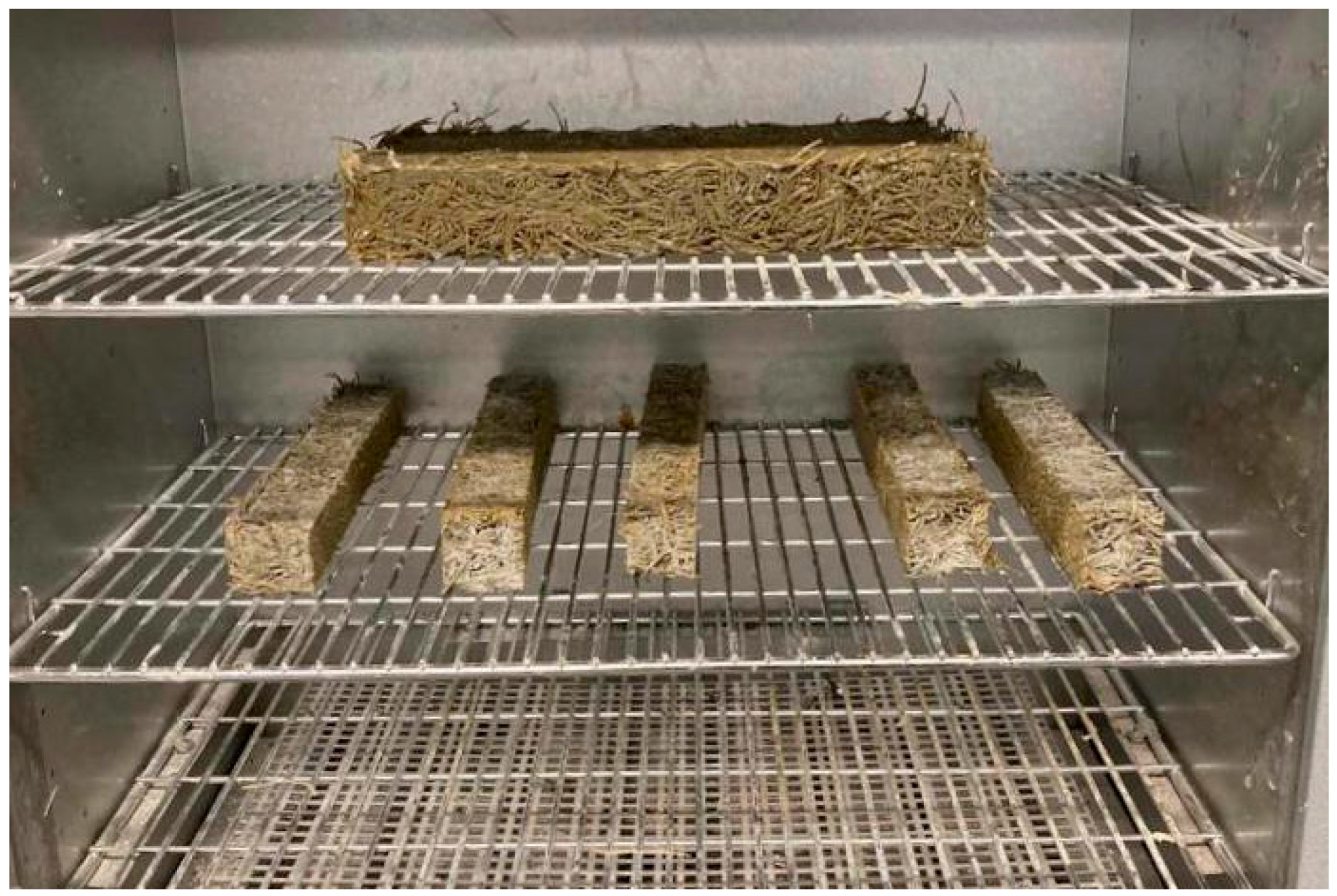
The specimens were demolded after 24 h. To ensure adequate moisture for cement hydration, each specimen was immediately wrapped tightly in plastic film, creating a sealed curing environment. The wrapped specimens were then stored at a room temperature of 23 ± 2 °C for 28 days. Following the curing period, the large composite beams were cut into smaller prismatic specimens for mechanical testing, as shown being prepared for drying in an oven in Figure 2.

2.4. Mechanical Testing

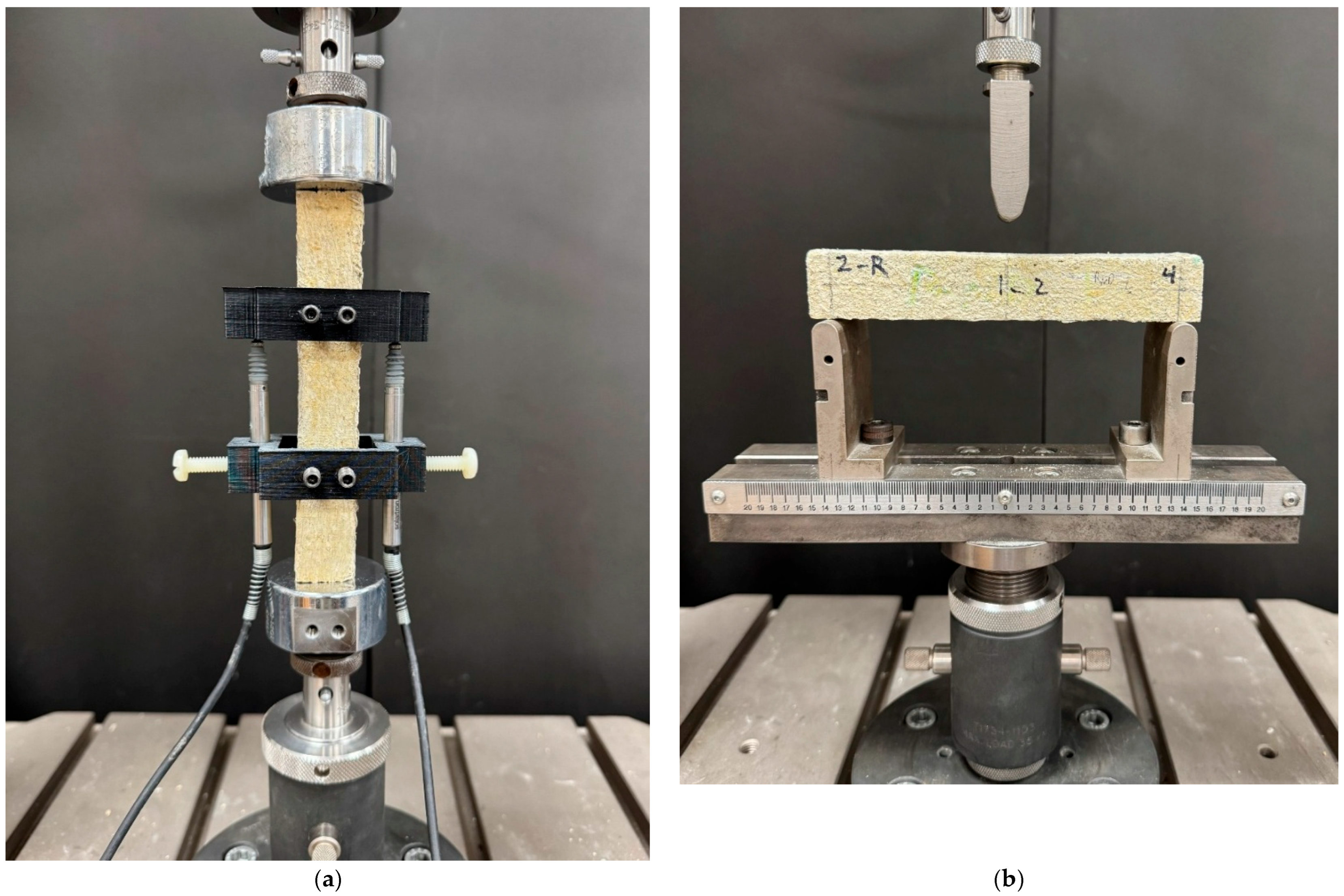
Mechanical tests were conducted using an Instron 8871 servo-hydraulic testing system. The testing configurations are shown in Figure 3. For each group, four specimens were tested for elastic modulus and four specimens were tested for flexural strength.
Elastic Modulus: A custom fixture was used to determine the elastic modulus (Figure 3a). Two 3D-printed fixtures were clamped to the specimen to define a central gage length. A pair of linear variable differential transformers (LVDTs) was mounted on opposite sides of the specimen to record axial strain directly. This method ensures higher accuracy compared to crosshead displacement measurements by minimizing boundary effects.
Flexural Testing: Flexural strength was evaluated in a three-point bending configuration on prismatic specimens (1 × 1 × 6 in.), as shown in Figure 3b. The support span was 5 inches. The loading rate was selected to produce failure within 1–2 min, following standard practice for cementitious composites. Load–deflection data were recorded continuously to determine the flexural strength (modulus of rupture).

2.5. Microstructural Characterization

The three-dimensional internal structure of the composites was analyzed non-destructively using X-ray computed tomography (XCT). The resulting volumetric datasets were processed using Avizo (Thermo Fisher Scientific, Waltham, MA, USA, v. 2024.2), a state-of-the-art software platform for advanced 3D visualization and quantitative microstructural analysis. The workflow and underlying algorithms were critical for extracting the quantitative data needed to establish the structure-property relationship.
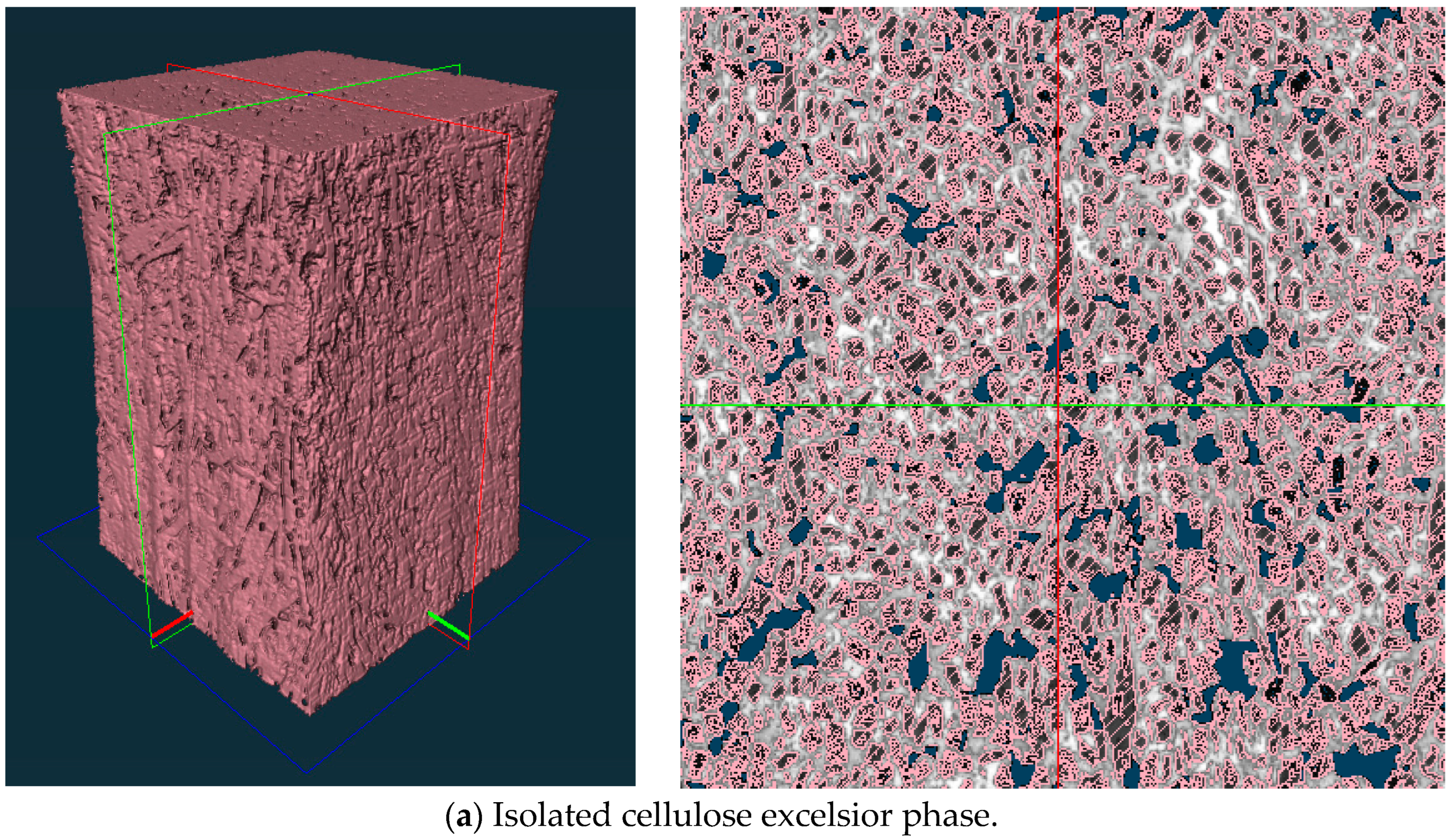
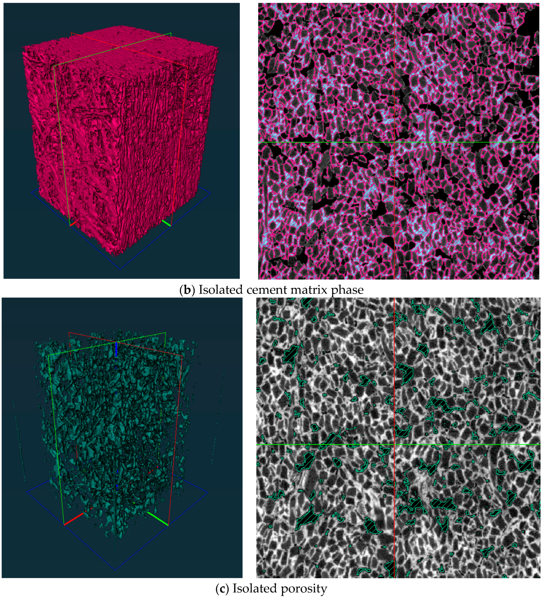
Segmentation of Phases: The primary step in the analysis was the segmentation of the XCT dataset into its constituent phases: CE fibers, cement matrix, and pores (voids). This was accomplished using an intensity-based thresholding algorithm. For a given grayscale intensity function f(x,y,z), the segmentation is mathematically defined by assigning voxels to a phase based on an intensity threshold, T. This was accomplished using an intensity-based thresholding algorithm. This method separates materials based on their different densities, which correspond to different grayscale values in the CT scan. Figure 4 shows a visual representation of this process, where the software has successfully identified the fibers, the matrix, and the pore spaces.
Morphological filtering operations, such as “Opening,” were then applied to the segmented data to remove small-scale imaging noise.
Pore Network Analysis: After segmentation, the total porosity (ϕ) of each specimen was calculated as the ratio of the pore volume to the total sample volume: ϕ = Vpores/Vtotal. Avizo computes this by summing the number of voxels classified as pores and multiplying by the known volume of a single voxel, as determined by the XCT scan resolution. This provided a direct, quantitative measure of the void content.
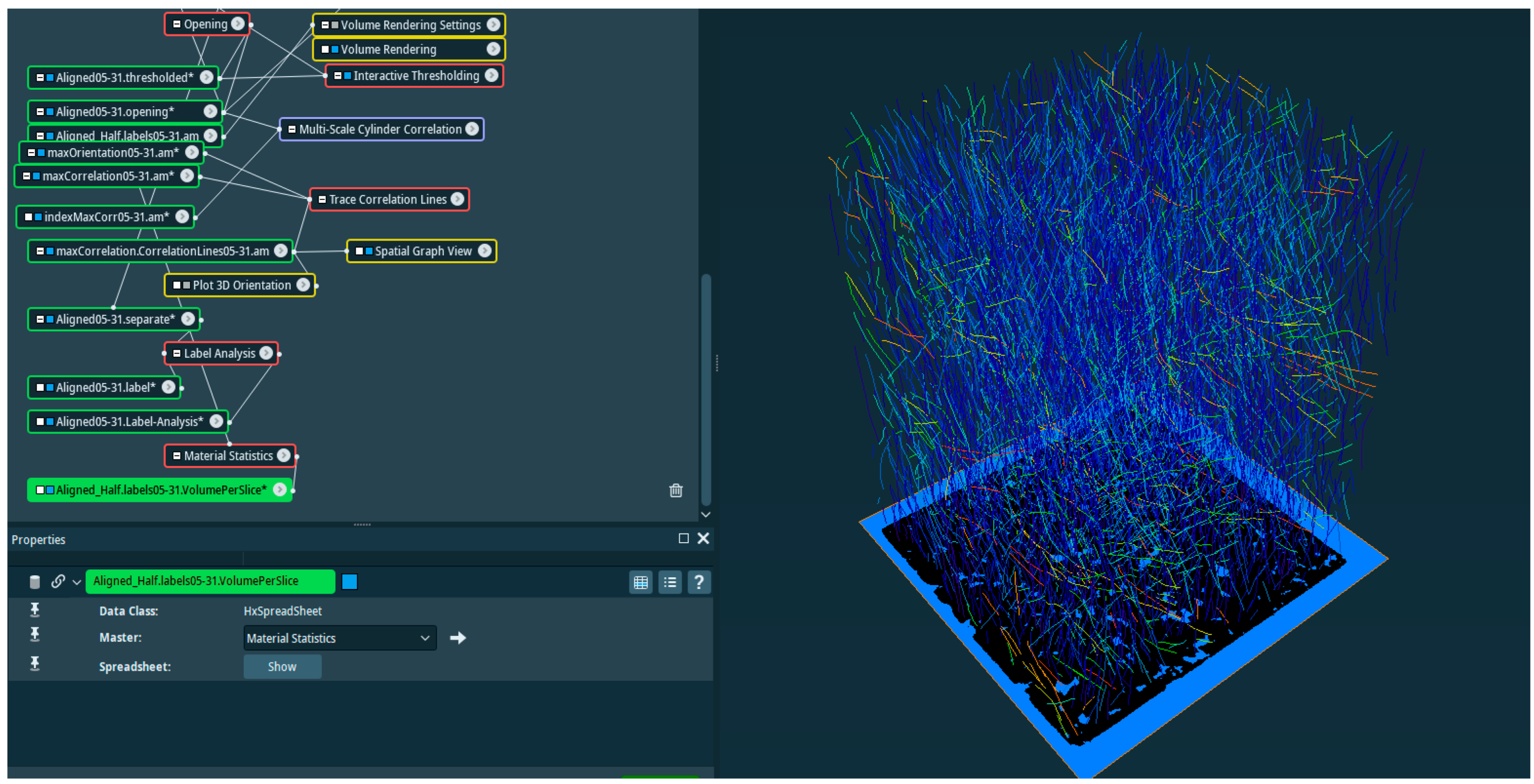
Fiber Orientation Quantification: The cornerstone of the microstructural analysis was the quantification of the 3D fiber orientation distribution. This was achieved in Avizo using an algorithm based on the analysis of the structure tensor. The structure tensor, J, is a matrix that describes the local orientation of features in an image based on the gradients of voxel intensities. By calculating the eigenvalues (λ1, λ2, λ3) and eigenvectors (v1, v2, v3) of this tensor at each point within a fiber, the principal orientation vector of that fiber segment can be determined. A histogram of the angles of these vectors relative to the specimen’s primary axis was generated, providing a statistical distribution of fiber alignment for both the RND and ALG specimens. The overall workflow, from raw data to orientation analysis, is depicted in the screenshot from the Avizo interface shown in Figure 5.

3. Results

3.1. Microstructural Properties: Porosity and Fiber Architecture

The fabrication methods produced composites with distinctly different internal architectures, as quantified by XCT analysis. The process of manual alignment and compressive consolidation resulted in a significantly denser composite. The aligned specimens registered an average bulk density of 1.12 g/cm3, a 20.4% increase over the 0.93 g/cm3 average density of the randomly oriented specimens.
This densification is a direct result of a more efficient packing of the solid constituents and a substantial reduction in the internal void space. As shown in Table 3, quantitative analysis of the XCT data revealed that the randomly oriented specimens possessed a high average porosity of 8.99%. In contrast, the aligned specimens contained an average porosity of only 5.11%. This represents a 43.2% reduction in void volume, demonstrating that the fabrication technique for the aligned samples was effective at minimizing entrapped air. The significant volume of interconnected pores within a typical randomly oriented specimen is visualized in the 3D rendering in Figure 6.
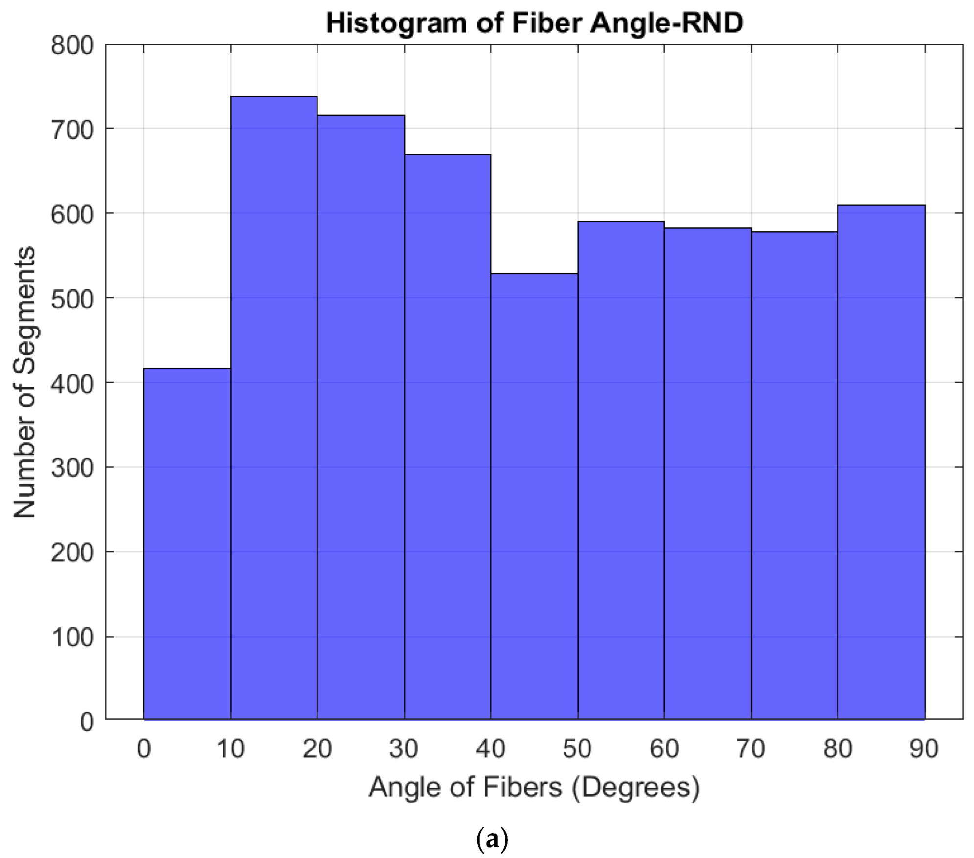
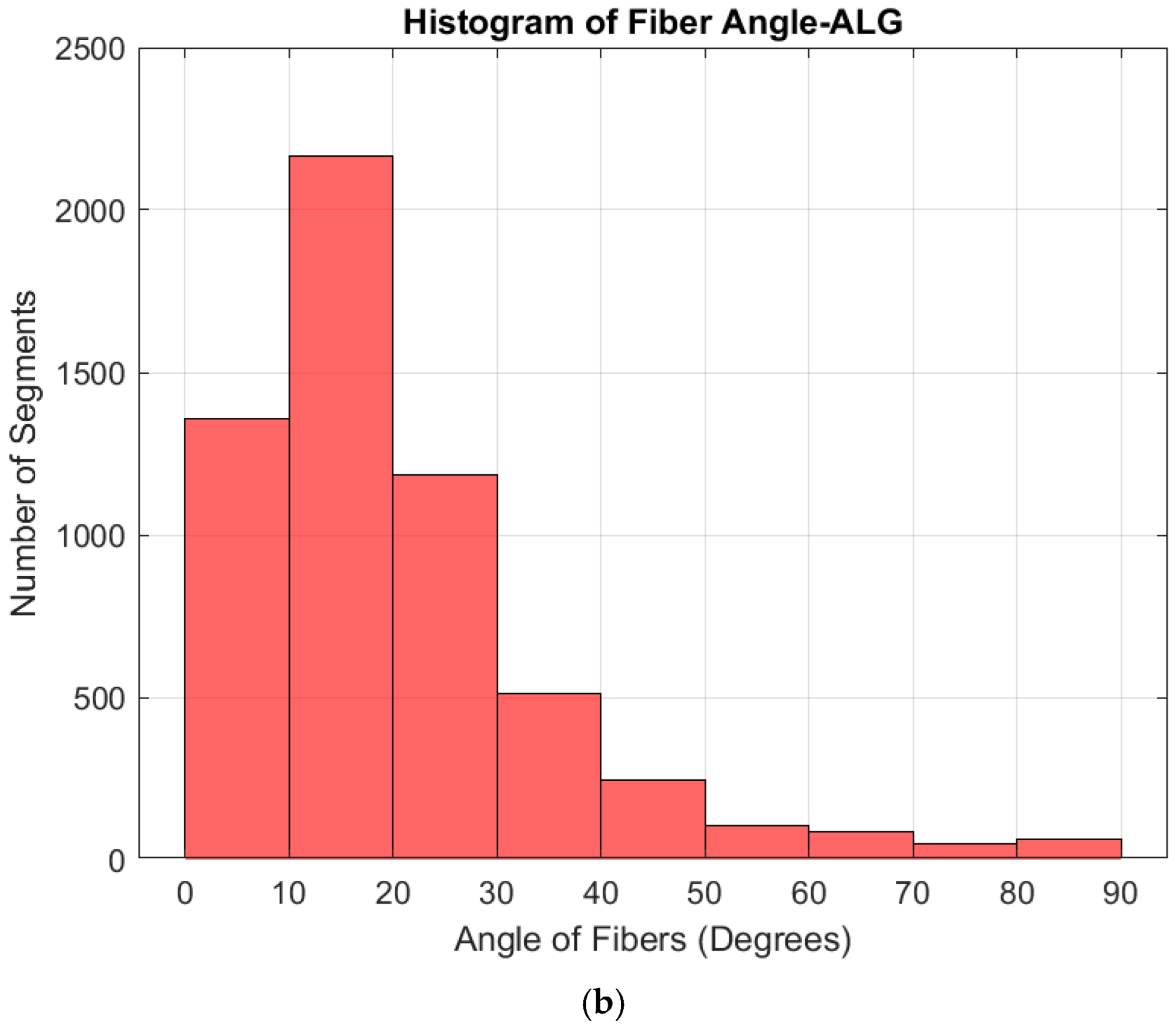
Beyond porosity, the most critical microstructural difference lies in the fiber orientation. The degree of alignment was quantified by analyzing the angular distribution of segmented fiber elements relative to the specimen’s longitudinal axis (the intended direction of alignment). The resulting histograms in Figure 7 provide a definitive, quantitative comparison. In this study, the term “randomly oriented” refers to the absence of intentional directional placement during fabrication rather than perfect mathematical randomness. Local fiber alignment may still occur during hand placement and compaction. Therefore, the RND group is interpreted as a non-intentionally aligned reference condition, while the XCT-based angle distribution is used to compare its fiber architecture with the intentionally aligned ALG group.
Figure 7a shows the fiber angle distribution for a representative RND specimen. The distribution is nearly uniform across all angle bins, from 0° (parallel) to 90° (transverse). This flat profile is the statistical signature of an isotropic material, confirming a chaotic and non-directional fiber network.
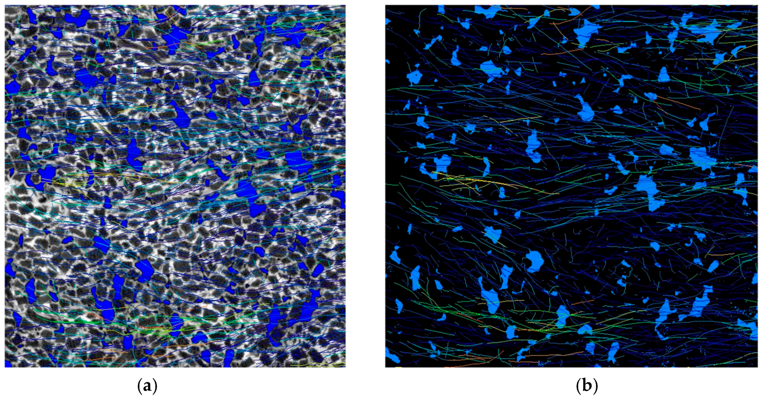
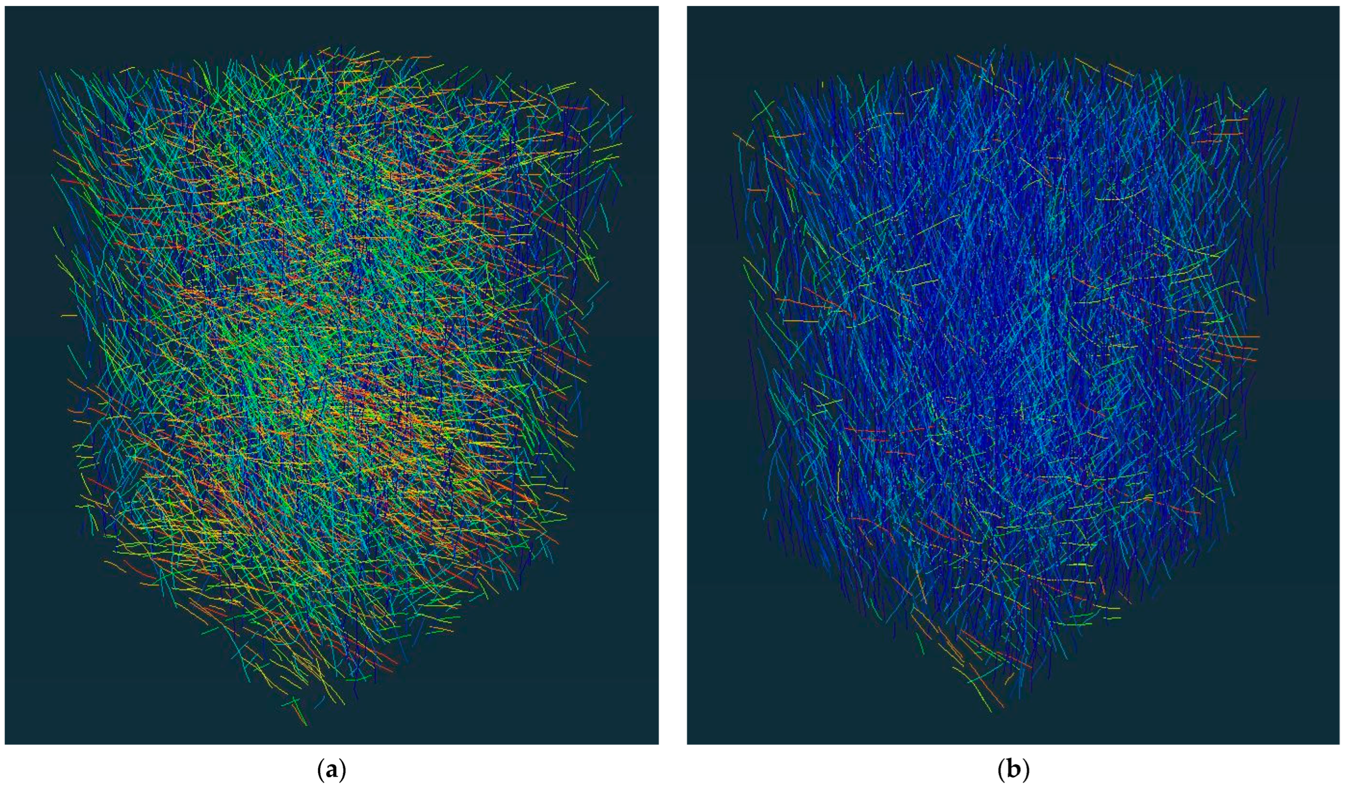
Conversely, Figure 7b illustrates the distribution for an ALG specimen. There is a dramatic shift in the distribution, with a strong modal peak observed for fiber angles between 10° and 20°. A significant majority of the fiber segments are concentrated below 30°, with the frequency decreasing sharply at higher angles. This highly skewed distribution serves as quantitative proof of a pronounced structural anisotropy, confirming the success of the alignment-focused fabrication technique. These statistical findings are visually corroborated by the 3D renderings in Figure 8, which contrast the disordered network of the random composite (Figure 8a) with the highly ordered, laminar structure of the aligned composite (Figure 8b).
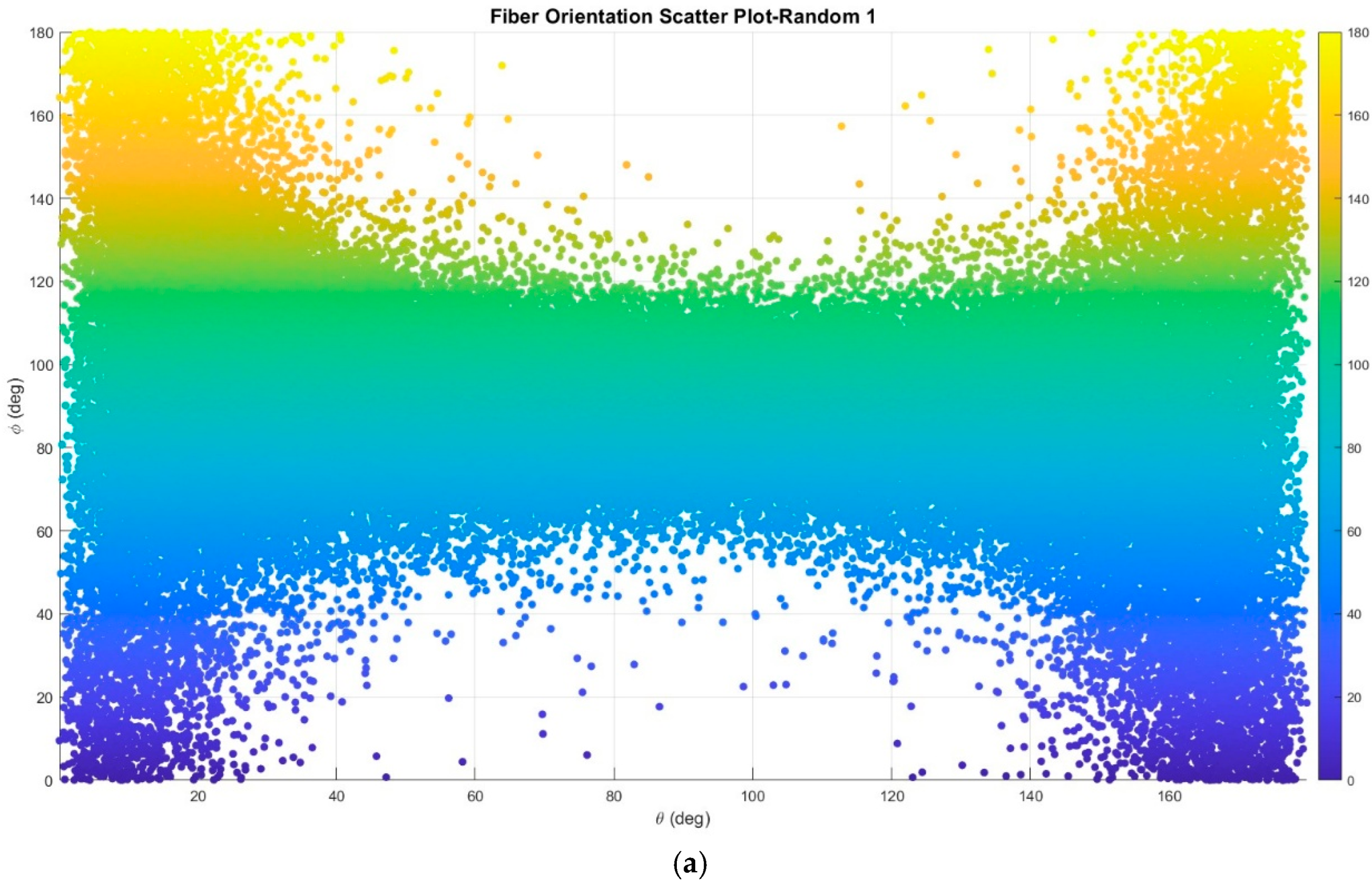
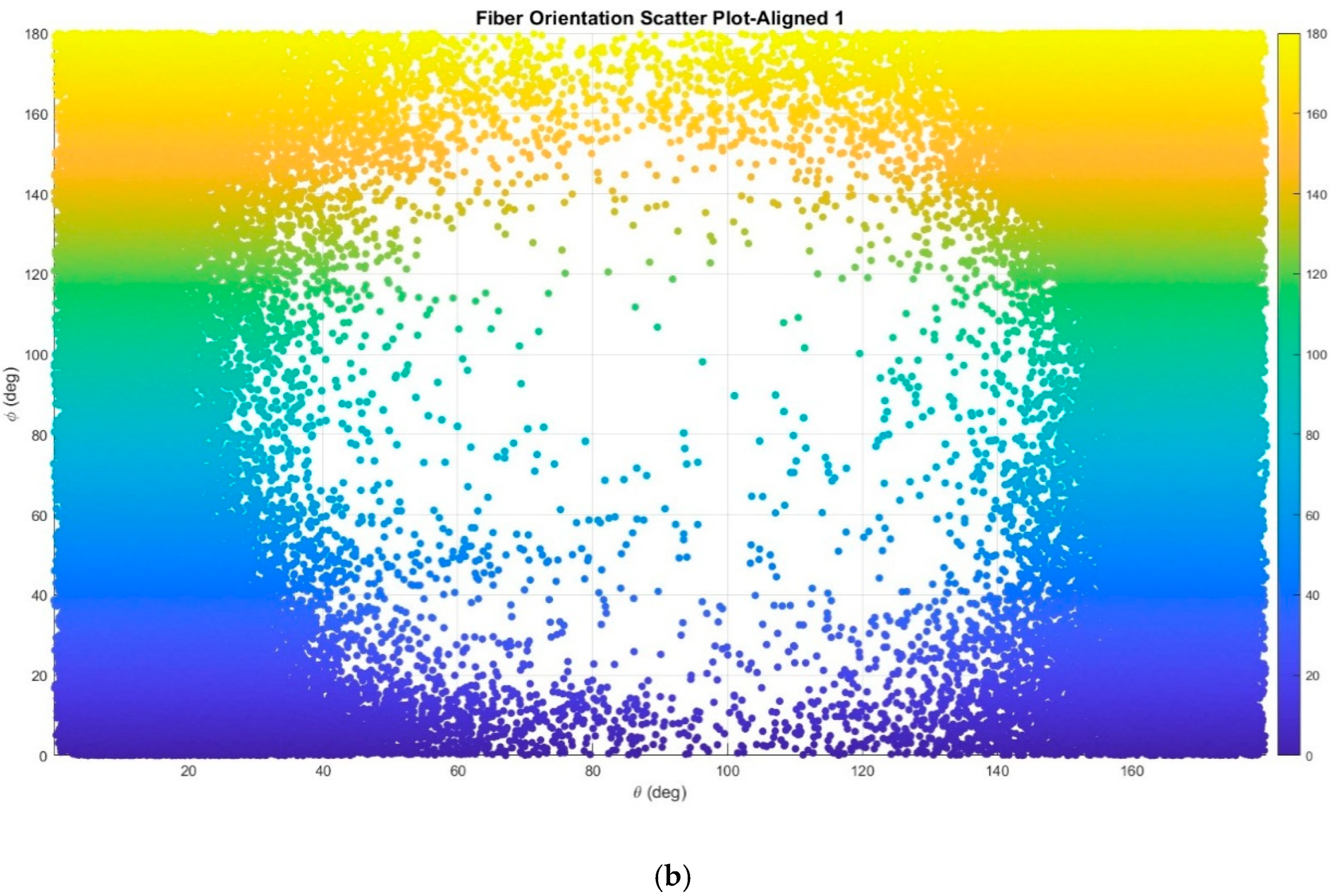
The orientation data can also be visualized using 2D scatter plots, which map each fiber segment according to its polar angle (θ) and azimuthal angle (ϕ), as shown in Figure 9. For the randomly oriented specimen (Figure 9a), the data points are spread relatively evenly across the entire plot, indicating that the fibers have no preferred direction in 3D space. In contrast, the scatter plot for the aligned specimen (Figure 9b) shows a dense concentration of data points at low ϕ values (primarily below 40 degrees), forming a distinct band at the bottom of the plot. This visualization further reinforces the conclusion from the histograms, providing a clear two-dimensional representation of the successful uniaxial alignment achieved in the ALG specimens.

3.2. Mechanical Performance

The profound differences in the internal microstructure translated directly into significant enhancements in the bulk mechanical properties. The aligned specimens consistently outperformed their randomly oriented counterparts in both stiffness (modulus of elasticity) and flexural strength.
The modulus of elasticity, a measure of the material’s stiffness, is detailed in Table 4. The RND specimens exhibited an average modulus of 0.65 GPa. However, the individual results for this group showed considerable variability. In stark contrast, the ALG specimens were substantially stiffer, yielding an average modulus of 1.45 GPa. This represents a 123% increase in average stiffness over the random composite group. Furthermore, the results for the aligned specimens were more consistent, with a lower coefficient of variation as shown in the table.
A similar improvement was observed in the flexural strength, measured via a three-point bending test. The results are summarized in Table 5. The RND specimens delivered an average flexural strength of 3.04 MPa. This group showed significant performance variation. The ALG specimens demonstrated a markedly superior and more reliable performance, with an average flexural strength of 4.79 MPa. This constitutes a 58% increase in strength compared to the isotropic baseline. The performance was also more predictable, with shown coefficient of variation. The flexural-strength results showed higher variability than the elastic-modulus results, particularly for the RND specimens. This scatter is expected in high-fiber-volume composites because local fiber packing, void distribution, and crack path development can vary among specimens. Therefore, the flexural results are interpreted primarily as an increase in mean performance and improved consistency for the ALG group, rather than as a complete statistical characterization of flexural behavior.

4. Discussion

This study established a quantitative structure–property relationship for cellulose excelsior–cement composites, demonstrating that engineering the internal fiber architecture can substantially improve mechanical performance. The superior properties of the aligned specimens can be attributed to the combined effects of two concurrent microstructural modifications: the creation of a highly anisotropic fiber network and a significant reduction in overall porosity.
The enhanced mechanical response of the ALG specimens should therefore be interpreted as the combined effect of preferential fiber alignment and densification. In the RND specimens, fibers were distributed over a wider range of orientations, meaning that only a portion of the fiber network was favorably positioned to resist tensile stresses during bending or contribute efficiently to axial stiffness. In contrast, the fabrication process for the ALG specimens produced a larger population of fibers oriented close to the longitudinal axis, as confirmed by the XCT analysis. This orientation allows more efficient stress transfer within the composite and improves the ability of the fiber network to resist deformation and bridge developing cracks. However, because the aligned fabrication route also reduced porosity and increased bulk density, the present experimental design does not fully separate the individual contributions of fiber orientation and densification. The observed increases in stiffness and mean flexural strength should therefore be understood as the result of a coupled architecture-control and densification process.
The reduction in porosity is also an important contributor to the improved performance. Pores and voids reduce the effective load-bearing cross-sectional area and can act as stress-concentration sites where cracks initiate and propagate. By reducing the void content from 8.99% to 5.11%, the aligned composites developed a denser and more continuous load-bearing skeleton. This lower void content, together with the more favorable fiber orientation, likely contributed to the higher elastic modulus and flexural strength observed in the ALG specimens. The 20.4% increase in bulk density further confirms the greater degree of consolidation achieved in the aligned specimens.
The results also highlight the importance of process control for performance reliability. The RND specimens showed greater variability, particularly in flexural strength, which is expected in high-fiber-volume composites where local fiber packing, void distribution, and crack-path development can vary from specimen to specimen. In comparison, the ALG specimens showed more consistent mechanical performance, indicating that controlled fiber placement and consolidation can reduce microstructural variability. From an engineering perspective, this improved consistency is important because it allows more predictable material behavior. Overall, the results show that controlled fiber architecture can transform cellulose excelsior–cement composites from a randomly packed fiber system into a more directionally reinforced composite with improved stiffness, higher mean flexural strength, and reduced porosity.

5. Conclusions

This research successfully demonstrated and quantified the significant benefits of controlled fiber orientation on the performance of cellulose excelsior–cement composites. Through a combination of targeted fabrication techniques and advanced 3D microstructural analysis, a clear relationship between the internal architecture and the bulk mechanical properties was established. The primary conclusions of this study are:
  • A fabrication method involving manual fiber placement and compressive consolidation was highly effective in creating an anisotropic composite, with XCT analysis confirming a strong preferential alignment of fibers along the longitudinal axis.
  • This fabrication process concurrently produced a denser, more consolidated material, reducing the total porosity by 43.2% (from 8.99% to 5.11%).
  • These engineered microstructural improvements translated directly into substantially enhanced mechanical performance, with a 123% increase in average modulus of elasticity and a 58% increase in average flexural strength.
  • The alignment process also resulted in a more reliable and predictable material, significantly reducing the variability in mechanical properties observed in the randomly oriented specimens.
By quantitatively linking microstructural features to macroscopic performance, this work demonstrates that microstructural engineering is an effective strategy for improving the mechanical response of cellulose excelsior–cement composites. The results show that fiber alignment and densification are not merely fabrication outcomes but key design parameters that influence stiffness, flexural strength, porosity, and performance consistency. These findings provide a basis for further development of sustainable bio-based cementitious composites, while future work should evaluate long-term durability, moisture sensitivity, fiber–matrix bonding, and the scalability of the alignment process for larger composite elements.

Author Contributions

Conceptualization, M.O. and E.N.L.; Methodology, M.O. and E.N.L.; Software, M.O.; Validation, M.O.; Formal analysis, M.O.; Investigation, M.O.; Resources, E.N.L.; Data curation, M.O.; Writing—original draft, M.O.; Writing—review & editing, E.N.L.; Supervision, E.N.L.; Project administration, E.N.L.; Funding acquisition, E.N.L. All authors have read and agreed to the published version of the manuscript.

Funding

This work was funded by the U.S. Dept. of Energy, award number DE-FOA-0001634.

Institutional Review Board Statement

Not applicable.

Informed Consent Statement

Not applicable.

Data Availability Statement

The data supporting the findings of this study are available from the corresponding author upon reasonable request. Due to file-size limitations, raw XCT datasets can be shared through an appropriate data-transfer method upon reasonable request.

Conflicts of Interest

The authors declare no conflict of interest.

References

  1. Liu, J.; Lv, C. Research progress on durability of cellulose fiber-reinforced cement-based composites. Int. J. Polym. Sci. 2021, 2021, 1014531. [Google Scholar] [CrossRef] [Scilit]
  2. Patel, K.; Kansagra, M.; Haji, A.; Prajapati, V.; Chauhan, D. Experimental study on properties of cellulose fiber concrete. Int. J. Sci. Res. Sci. Technol. 2018, 4, 702–710. [Google Scholar] [CrossRef] [Scilit]
  3. Bodnárová, L.; Kostelanská, K.; Jankech, F. The possibilities of application of cellulose fibers in cement composites, monitoring the properties. Adv. Mater. Res. 2014, 1054, 85–89. [Google Scholar] [CrossRef] [Scilit]
  4. Han, J.; Choi, Y. Microstructural characteristics of cellulosic fiber-reinforced cement composite. Materials 2024, 18, 59. [Google Scholar] [CrossRef] [Scilit] [PubMed]
  5. Fernando, S.; Gunasekara, C.; Shahpasandi, A.; Nguyen, K.; Sofi, M.; Setunge, S.; Mendis, P.; Rahman, T. Sustainable cement composite integrating waste cellulose fibre: A comprehensive review. Polymers 2023, 15, 520. [Google Scholar] [CrossRef] [Scilit] [PubMed]
  6. Claramunt, J.; Ardanuy, M.; Fernández-Carrasco, L. Wet/dry cycling durability of cement mortar composites reinforced with micro- and nanoscale cellulose pulps. Bioresources 2015, 10, 3045–3055. [Google Scholar] [CrossRef] [Scilit]
  7. Tonoli, G.; Mendes, R.; Siqueira, G.; Bras, J.; Belgacem, M.; Savastano, H. Isocyanate-treated cellulose pulp and its effect on the alkali resistance and performance of fiber cement composites. Holzforschung 2013, 67, 853–861. [Google Scholar] [CrossRef] [Scilit]
  8. Teixeira, R.; Tonoli, G.; Santos, S.; Rayón, E.; Amigó, V.; Savastano, H.; Lahr, F.R. Nanoindentation study of the interfacial zone between cellulose fiber and cement matrix in extruded composites. Cem. Concr. Compos. 2018, 85, 1–8. [Google Scholar] [CrossRef] [Scilit]
  9. Hospodarova, V.; Števulová, N.; Václavík, V.; Dvorský, T.; Briančin, J. Cellulose fibres as a reinforcing element in building materials. Environ. Eng. 2017, 10, 1–8. [Google Scholar] [CrossRef] [Scilit]
  10. Liu, J.; Lv, C. Durability of cellulosic-fiber-reinforced geopolymers: A review. Molecules 2022, 27, 796. [Google Scholar] [CrossRef] [Scilit] [PubMed]
  11. Raghunath, S.; Hoque, M.; Foster, E. On the roles of cellulose nanocrystals in fiber cement: Implications for rheology, hydration kinetics, and mechanical properties. ACS Sustain. Chem. Eng. 2023, 11, 10727–10736. [Google Scholar] [CrossRef] [Scilit] [PubMed]
  12. Yusrizal, Y.; Rahmawati, C.; Zardi, M.; Aprilia, S.; Aulia, T.; Iqbal, I. Exploring concepts and aplication of natural fibers on cement-based composites. In Proceedings of the 2nd International Conference on Environmental, Energy, and Earth Science, ICEEES 2023, Pekanbaru, Indonesia, 30 October 2023. [Google Scholar] [CrossRef] [Scilit]
  13. Thipchai, P.; Jantanasakulwong, K.; Sawangrat, C.; Suhr, J.; Khotchapong, K.; Wattanachai, P.; Rachtanapun, P. Microstructural characterization of cellulose nanocrystals and microcellulose from bamboo (Bambusa longispatha) for reinforcing ordinary portland cement matrix. Polymers 2024, 16, 3558. [Google Scholar] [CrossRef] [Scilit] [PubMed]
  14. Lauer, M.; Estrada-Mendoza, T.; McMillen, C.; Chumanov, G.; Tennyson, A.; Smith, R. Durable cellulose–sulfur composites derived from agricultural and petrochemical waste. Adv. Sustain. Syst. 2019, 3, 62. [Google Scholar] [CrossRef] [Scilit]
  15. Guo, J.; Li, Q.; Zhang, R.; Li, B.; Zhang, J.; Yao, L.; Lin, Z.; Zhang, L.; Cao, X.; Duan, B. Loose pre-cross-linking mediating cellulose self-assembly for 3d printing strong and tough biomimetic scaffolds. Biomacromolecules 2022, 23, 877–888. [Google Scholar] [CrossRef] [Scilit] [PubMed]
  16. Kim, J.; Yun, K.; Kim, J.; Kim, J. Mechanical stretching effect on the actuator performance of cellulose electroactive paper. Smart Mater. Struct. 2009, 18, 055005. [Google Scholar] [CrossRef] [Scilit]
  17. Gao, L.; Zhao, X.; Zhou, Q.; Li, H.; Yu, H. Influence of cmc, hpmc, and cnf on performance of corrugated base paper. Chemistryselect 2024, 9, e202304818. [Google Scholar] [CrossRef] [Scilit]
  18. Abbott, A.; Bismarck, A. Self-reinforced cellulose nanocomposites. Cellulose 2010, 17, 779–791. [Google Scholar] [CrossRef] [Scilit]
  19. Zhang, Q.; Wang, Z.; Hao, S.; Huang, J. Preparation of all-cellulose composites based on controlled dissolution procedure. Starch-Stärke 2021, 73, 280. [Google Scholar] [CrossRef] [Scilit]
  20. Jiang, K.; Yan, Z.; Fang, W.; Zhang, Y. Effect of moisture content on the microscopic properties of amorphous cellulose: A molecular dynamics simulations. Mater. Res. Express 2022, 9, 125308. [Google Scholar] [CrossRef] [Scilit]
  21. Wei, P.; Yu, X.; Fang, Y.; Wang, L.; Zhang, H.; Zhu, C.; Cai, J. Strong and tough cellulose hydrogels via solution annealing and dual cross-linking. Small 2023, 19, 2301204. [Google Scholar] [CrossRef] [Scilit] [PubMed]
  22. Uto, K.; Liu, Y.; Mu, M.; Yamamoto, R.; Tenjimbayashi, M.; Kaeser, A.; Marliac, M.; Alam, M.M.; Sasai, J.; Azechi, C.; et al. Humidity-responsive polyvinyl alcohol/microcrystalline cellulose composites with shape memory features for hair-styling applications. Adv. Mater. Interfaces 2023, 11, 2300274. [Google Scholar] [CrossRef] [Scilit]
  23. Huang, H.; Liu, C.; Li, D.; Chen, Y.; Zhong, G.; Li, Z. Ultra-low gas permeability and efficient reinforcement of cellulose nanocomposite films by well-aligned graphene oxide nanosheets. J. Mater. Chem. A 2014, 2, 15853–15863. [Google Scholar] [CrossRef] [Scilit]
  24. Ishii, D.; Saito, T.; Isogai, A. Viscoelastic evaluation of average length of cellulose nanofibers prepared by tempo-mediated oxidation. Biomacromolecules 2011, 12, 548–550. [Google Scholar] [CrossRef] [Scilit] [PubMed]
  25. Menezes-Silva, R.; Carvalho, V.; Dumont, V.; Santos, M.; Carvalho, A. Addition of mechanically processed cellulosic fibers to ionomer cement: Mechanical properties. Braz. Oral Res. 2015, 29, 1–8. [Google Scholar] [CrossRef] [Scilit] [PubMed]
  26. Patel, P.; Wayal, A.; Bharimalla, A. Performance evaluation of cement mortar blended nanofibrillated cellulose. Int. J. Civ. Eng. Technol. 2020, 11, 169–176. [Google Scholar] [CrossRef] [Scilit]
  27. Mazlan, D.; Krishnan, S.; Din, M.; Tokoro, C.; Khalid, N.; Ibrahim, I.; Takahashi, H.; Komori, D. Effect of cellulose nanocrystals extracted from oil palm empty fruit bunch as green admixture for mortar. Sci. Rep. 2020, 10, 6412. [Google Scholar] [CrossRef] [Scilit] [PubMed]
  28. Mohammadkazemi, F.; Aguiar, R.; Cordeiro, N. Improvement of bagasse fiber–cement composites by addition of bacterial nanocellulose: An inverse gas chromatography study. Cellulose 2017, 24, 1803–1814. [Google Scholar] [CrossRef] [Scilit]
  29. Hospodarova, V.; Števulová, N.; Junák, J.; Geffert, A.; Kačík, F.; Briančin, J. Cement materials based on cellulosic fibers for plasters. Sel. Sci. Pap. J. Civ. Eng. 2017, 12, 37–46. [Google Scholar] [CrossRef] [Scilit]
  30. Kidalova, L.; Števulová, N.; Geffert, A. Possibility of using wood pulp in the preparation of cement composites. Sel. Sci. Pap. J. Civ. Eng. 2014, 9, 51–58. [Google Scholar] [CrossRef] [Scilit]
  31. Martínez-Barrera, G.; Barrera-Díaz, C.; Cuevas-Yáñez, E.; Varela-Guerrero, V.; Vigueras-Santiago, E.; Córdoba, L.; Martínez-López, M. Waste cellulose from tetra pak packages as reinforcement of cement concrete. Adv. Mater. Sci. Eng. 2015, 2015, 82926. [Google Scholar] [CrossRef] [Scilit]
  32. Uddin, A.; Araki, J.; Gotoh, Y. Toward “strong” green nanocomposites: Polyvinyl alcohol reinforced with extremely oriented cellulose whiskers. Biomacromolecules 2011, 12, 617–624. [Google Scholar] [CrossRef] [Scilit] [PubMed]
  33. Chen, S.; Schueneman, G.; Pipes, R.; Youngblood, J.; Moon, R. Effects of crystal orientation on cellulose nanocrystals–cellulose acetate nanocomposite fibers prepared by dry spinning. Biomacromolecules 2014, 15, 3827–3835. [Google Scholar] [CrossRef] [Scilit] [PubMed]
  34. Takagi, H.; Nakagaito, A.; Sakaguchi, Y. Fiber orientation control by stretching in cellulose nanofiber green composites. Key Eng. Mater. 2017, 754, 135–138. [Google Scholar] [CrossRef] [Scilit]
  35. Takagi, H.; Nakagaito, A.; Nishimura, K.; Matsui, T. Mechanical characterisation of nanocellulose composites after structural modification. WIT Trans. Built Environ. 2016, 166, 335–341. [Google Scholar] [CrossRef] [Scilit]
  36. Moreira, R.; Simão, J.; Gouveia, R.; Strauss, M. Exploring the hierarchical structure and alignment of wood cellulose fibers for bioinspired anisotropic polymeric composites. ACS Appl. Bio Mater. 2020, 3, 2193–2200. [Google Scholar] [CrossRef] [Scilit] [PubMed]
  37. Fujisawa, S.; Togawa, E.; Hayashi, N. Orientation control of cellulose nanofibrils in all-cellulose composites and mechanical properties of the films. J. Wood Sci. 2015, 62, 174–180. [Google Scholar] [CrossRef] [Scilit]
  38. Bertolini, M.; Campos, C.; Souza, A.; Panzera, T.; Christoforo, A.; Lahr, F. Wood-cement composites from wastes of Pinus sp. wood: Effect of particles treatment. Int. J. Compos. Mater. 2014, 4, 146–149. [Google Scholar] [CrossRef] [Scilit]
  39. Ilmaliyev, Z.; Zhatkanbayev, Y.; Kurtibay, K. Research and development of wood-cement composites as sustainable building materials based on secondary resources. Complex Use Mineral. Resour. 2024, 335, 34–41. [Google Scholar] [CrossRef] [Scilit]
  40. Aina, K. Influences of cement brands and mixing ratios on the physico-mechanical properties of cement bonded particleboards made of wood particles of gmelina arborea, afzelia africana and triplochiton scleroxylon. Balt. For. 2022, 28, 144–153. [Google Scholar] [CrossRef] [Scilit]
  41. Amiandamhen, S.; Agwu, C.; Ezenwaegbu, P. Evaluation of cement-bonded particleboards produced from mixed sawmill residues. J. Indian Acad. Wood Sci. 2021, 18, 14–19. [Google Scholar] [CrossRef] [Scilit]
  42. Engone, J.; Moumen, A.; Djelal, C.; Imad, A.; Kanit, T.; Page, J. Evaluation of effective elastic properties for wood–cement composites: Experimental and computational investigations. Sustainability 2022, 14, 8638. [Google Scholar] [CrossRef] [Scilit]
  43. Yel, H.; Aras, U.; Kalaycıoğlu, H.; Aykan, R. Cement-bonded wood panels filled with duroplast sanitary ware wastes. Maderas Cienc. Tecnol. 2024, 27. [Google Scholar] [CrossRef] [Scilit] [PubMed]
  44. Frömel-Frybort, S.; Mauritz, R.; Teischinger, A.; Müller, U. Investigation of the mechanical interactions at the interface of wood-cement composites by means of electronic speckle pattern interferometry. Bioresources 2012, 7, 2483–2495. [Google Scholar] [CrossRef] [Scilit]
  45. Lima, A.; Iwakiri, S.; Satyanarayana, K.; Lomelí-Ramírez, M. Studies on the durability of wood-cement particleboards produced with residues of Pinus spp., silica fume, and rice husk ash. Bioresources 2020, 15, 3064–3086. [Google Scholar] [CrossRef] [Scilit]
  46. Aigbomian, E.; Fan, M. Development of wood-crete from hardwood and softwood sawdust. Open Constr. Build. Technol. J. 2013, 7, 108–117. [Google Scholar] [CrossRef] [Scilit]
  47. Quiroga, A.; Marzocchi, V.; Rintoul, I. Influence of wood treatments on mechanical properties of wood–cement composites and of populus euroamericana wood fibers. Compos. Part B Eng. 2016, 84, 25–32. [Google Scholar] [CrossRef] [Scilit]
  48. Gao, Y.; Hu, W.; Xin, S.; Sun, L. A review of applications of ct imaging on fiber reinforced composites. J. Compos. Mater. 2021, 56, 133–164. [Google Scholar] [CrossRef] [Scilit]
  49. Maire, É.; Withers, P. Quantitative X-ray tomography. Int. Mater. Rev. 2013, 59, 1–43. [Google Scholar] [CrossRef] [Scilit]
  50. Thi, T.; Morioka, M.; Yokoyama, A.; Hamanaka, S.; Yamashita, K.; Nonomura, C. Measurement of fiber orientation distribution in injection-molded short-glass-fiber composites using X-ray computed tomography. J. Mater. Process. Technol. 2015, 219, 1–9. [Google Scholar] [CrossRef] [Scilit]
  51. Zabler, S.; Schladitz, K.; Dremel, K.; Graetz, J.; Dobrovolskij, D. Region-of-interest X-ray tomography for the non-destructive characterization of local fiber orientation in large fiber composite parts. Key Eng. Mater. 2019, 809, 587–593. [Google Scholar] [CrossRef] [Scilit]
  52. Tausif, M.; Duffy, B.; Grishanov, S.; Carr, H.; Russell, S. Three-dimensional fiber segment orientation distribution using X-ray microtomography. Microsc. Microanal. 2014, 20, 1294–1303. [Google Scholar] [CrossRef] [Scilit] [PubMed]
  53. Suzuki, Y.; Cousins, D.; Dorgan, J.; Stebner, A.; Kappes, B. Dual-energy X-ray computed tomography for void detection in fiber-reinforced composites. J. Compos. Mater. 2019, 53, 2349–2359. [Google Scholar] [CrossRef] [Scilit]
  54. Zou, C.; Marrow, T.; Reinhard, C.; Li, B.; Zhang, C.; Wang, S. Porosity characterization of fiber-reinforced ceramic matrix composite using synchrotron X-ray computed tomography. J. Instrum. 2016, 11, C03052. [Google Scholar] [CrossRef] [Scilit]
  55. Evdokov, O.; Kozyrev, A.; Litvinenko, V.; Lukianchikov, L.; Merzhievsky, L.; Pruué, É.; Tolochko, B.; Zhogin, I.; Zubkov, P. High-speed X-ray transmission tomography for detonation investigation. Nucl. Instrum. Methods Phys. Res. Sect. A Accel. Spectrometers Detect. Assoc. Equip. 2007, 575, 116–120. [Google Scholar] [CrossRef] [Scilit]
  56. ASTM D4442-20; Standard Test Methods for Direct Moisture Content Measurement of Wood and Wood-Based Materials. ASTM International: West Conshohocken, PA, USA, 2020. [CrossRef] [Scilit]
Figure 1. Specimen consolidation setup. The filled mold is placed in an Instron 5900R testing machine (Norwood, MA, USA), which applies a sustained compressive load to densify the composite and expel excess water and air.
Applsci 16 08416 g001
Figure 2. Cured prismatic specimens cut from a larger beam, placed in a laboratory oven for drying according to ASTM D4442 [56] prior to mechanical testing.
Applsci 16 08416 g002
Figure 3. Mechanical testing configurations. (a) Setup for elastic modulus measurement, featuring a custom fixture with dual LVDTs for high-accuracy direct strain measurement. (b) Standard three-point bending test setup used for the determination of flexural strength.
Applsci 16 08416 g003
Figure 4. Visual representation of the image segmentation results. Each set of images show a 3D rendering (left) and a slice image (right) of the isolated material phase. (a) shows the cellulose excelsior, (b) shows the cement matrix, and (c) shows the pore space. The 3D renderings illustrate the connectivity of the different phases, particularly in the case of the fibers and the cement matrix, where there is nearly complete connectivity of the phase, while the 3D rendering of the pore space shows a more disconnected network.
Applsci 16 08416 g004aApplsci 16 08416 g004b
Figure 5. Screenshot of the Avizo software (v. 2024.2) interface showing the project workflow for an aligned specimen. The workflow includes modules for interactive thresholding, multi-scale cylinder correlation for fiber identification, and plotting of the 3D orientation.
Applsci 16 08416 g005
Figure 6. 3D visualization of the segmented pore network within a randomly oriented wood–cement composite specimen reconstructed from XCT data: (a) representative segmented cross-section showing the spatial distribution of pores within the cementitious matrix and fiber network; and (b) 3D reconstructed pore network highlighting the interconnected void structure. The segmented pores are shown in teal/blue. The visualization indicates a significant and interconnected void system, corresponding to a measured porosity of 8.9%.
Applsci 16 08416 g006
Figure 7. (a) Histogram for a randomly oriented (RND) specimen, showing a uniform, isotropic distribution of fiber angles. (b) Histogram for an aligned (ALG) specimen, showing a highly anisotropic distribution with a strong modal peak between 10° and 20°.
Applsci 16 08416 g007aApplsci 16 08416 g007b
Figure 8. 3D renderings of the segmented fiber networks. (a) The isotropic and disordered fiber arrangement in a randomly oriented specimen. (b) The anisotropic and highly ordered fiber arrangement in an aligned specimen. Fibers are color-coded by their angle relative to the primary axis (blue is parallel).
Applsci 16 08416 g008
Figure 9. Fiber orientation scatter plots for (a) a representative randomly oriented specimen and (b) a representative aligned specimen. The plots show the distribution of fiber segments according to the polar angle (θ) and the azimuthal angle (ϕ). The uniform spread of points in (a) confirms an isotropic distribution, while the concentration of points at low ϕ values in (b) visually demonstrates a high degree of uniaxial alignment.
Applsci 16 08416 g009aApplsci 16 08416 g009b
Table 1. Physical properties of the constituent materials as determined for mix design calculations.
MaterialConditionDensity (kg/m3)
Portland Limestone Cement (PLC)-3050
Water-1000
Cellulose Excelsior (CE)Oven-Dry420
Cellulose Excelsior (CE)Saturated Surface-Dry (SSD)980
Table 2. Chemical properties of PLC.
OxidesContent (%)
SiO220.2
Al2O33.6
Fe2O33.2
CaO65.1
MgO3.0
SO33.4
Na2O0.3
Table 3. Comparison of average physical and microstructural properties for the two composite sets.
PropertyRandomly Oriented (RND)Aligned (ALG)% Change
Bulk Density (g/cm3)0.931.12+20.4%
Porosity (%)8.995.11−43.2%
Table 4. Modulus of Elasticity for Randomly Oriented and Aligned Specimens.
Specimen TypeSpecimen NameModulus of Elasticity (GPa)Average (GPa)Standard Deviation (GPa)COV (%)
Randomly OrientedRND 10.7230.650.07010.7
RND 20.682
RND 30.561
RND 40.634
AlignedALG 11.3271.450.1117.7
ALG 21.593
ALG 31.466
ALG 41.414
Table 5. Flexural Strength for Randomly Oriented and Aligned Specimens.
Specimen TypeSpecimen NameFlexural Strength (MPa)Average (MPa)Standard Deviation (MPa)COV (%)
Randomly OrientedRND 13.293.041.3243.4
RND 22.52
RND 31.59
RND 44.75
AlignedALG 15.474.791.1323.6
ALG 23.13
ALG 35.14
ALG 45.42
Disclaimer/Publisher’s Note: The statements, opinions and data contained in all publications are solely those of the individual author(s) and contributor(s) and not of MDPI and/or the editor(s). MDPI and/or the editor(s) disclaim responsibility for any injury to people or property resulting from any ideas, methods, instructions or products referred to in the content.