Article

Research on Electric Field Distribution and Shielding Measures for Houses near a 1000 kV UHV AC Transmission Line

1
State Grid Anhui Electric Power Research Institute, Hefei 230601, China
2
Institute of Next Generation Power Systems and International Standards, Wuhan University, Wuhan 430072, China
*
Author to whom correspondence should be addressed.
Appl. Sci. 2026, 16(15), 7855; https://doi.org/10.3390/app16157855
Submission received: 23 June 2026 / Revised: 2 August 2026 / Accepted: 3 August 2026 / Published: 6 August 2026
(This article belongs to the Section Electrical, Electronics and Communications Engineering)

Abstract

In recent years, UHV AC/DC transmission projects in China have developed rapidly, and transmission line corridors have become increasingly limited. As a result, UHV AC transmission lines are increasingly located near areas where residents live and work, and the electric field distribution around houses near transmission lines has become a major public concern. To further investigate the electric field around houses near UHV transmission lines, a full-scale house platform was constructed near an actual operating 1000 kV AC transmission line. The electric field distribution above the house platform and around the house was systematically measured and analyzed. The effects of house height and the distance between the house and the transmission line on the electric field distribution were discussed, with emphasis on the electric field distribution on the two-story platform. In addition, the shielding effect of shielding wires installed near the house on the electric field of the house platform was analyzed. The results show that the electric field on the two-story platform is significantly higher than that on the single-story platform, and the electric field decreases approximately linearly with distance. Installing shielding wires can effectively reduce the power-frequency electric field intensity on the house platform. A relatively optimal balance between shielding performance and installation economy can be achieved when the shielding wire is installed along the edge of the house, with a length 3 m longer than the house edge and a height 1.5 m higher than the position to be shielded. A reasonable combination of multiple shielding wires provides a much better shielding effect than a single shielding wire.

1. Introduction

With the development of the national economy, electricity consumption in China has continued to increase, and the scale of ultra-high-voltage (UHV) transmission projects has also continued to expand [1,2]. Owing to the shortage of land resources, the available options for transmission corridors have become increasingly limited. As a result, UHV transmission lines have become increasingly common near areas where residents live and work, especially in densely populated provinces in central and eastern China. When UHV AC transmission lines pass near houses, the electric field on house platforms may become relatively strong, which can easily induce transient electric shocks and cause discomfort or even complaints from residents. Therefore, studying the electric field distribution and control measures on house platforms near actual transmission lines is of great significance for ensuring a favorable electromagnetic environment in residential areas and improving residents’ quality of life.
Early studies examined electric-field measurements near residences and methods for reducing transmission-line electric fields. Caola et al. measured electric and magnetic fields in and around homes adjacent to a 500 kV transmission line and reported that house walls provided shielding from the transmission-line electric field [3]. Deno investigated electric-field reduction beneath a UHV transmission line using a grid of parallel horizontal wires [4]. Deno et al. quantified the reduction of 60 Hz electric fields caused by grounded objects near high-voltage transmission lines using shielding functions related to the object geometry and the distance from the object [5]. These studies provided an important basis for the measurement, evaluation, and mitigation of transmission-line electric fields near houses and other structures. More recent studies on the power-frequency electric field near transmission lines mainly focus on numerical calculation methods. These methods can generally be divided into two categories. The first category is based on the Laplace or Poisson equations for boundary-value problems and transforms the problem in a continuous domain into a discrete system for solution, including the finite difference method [6] and the finite element method [7,8]. The second category takes a set of fictitious charges as unknowns and solves the integral equation for calculating the electric potential from the charge distribution according to Coulomb’s law, including the charge simulation method [9,10,11,12,13] and the method of moments [14,15,16,17]. In 2019, Luo Richeng et al. used the charge simulation method to analyze the power-frequency electric field at a height of 1.5 m beneath a 500 kV AC transmission line, investigated the shielding effect of shielding wires on the electric field, and determined the optimal arrangement scheme for the shielding wires [18]. In 2017, Peng Chunhua et al. used a machine learning method to summarize a large amount of shielding data for the electric field around houses obtained by finite element calculations, and proposed an optimal shielding scheme involving four parameters: the number of shielding wires, shielding wire spacing, horizontal distance, and corrected height [19]. In 2016, Tong Z. et al. studied the electric field in the window area of buildings near 500 kV AC transmission lines and proposed an effective shielding measure by installing metal eaves along the edge of the building roof [20]. In 2015, Wu Guifang et al. calculated the electric field around houses near transmission lines using the finite element method and established a field model for comparison, thereby verifying the accuracy of the calculation results [21]. In the same year, Wu Guifang et al. conducted human electric shock perception experiments and proposed recommendations on limits for the power-frequency electric field on house platforms [22]. In 2013, Huang Zixuan et al. improved the charge simulation method by arranging fictitious charges on the building surface using a honeycomb mesh division, and calculated the power-frequency electric field near high-voltage AC transmission lines in the presence of buildings [23].
Although previous studies have investigated transmission-line electric fields through theoretical analysis, numerical calculation, and field measurements, experimental studies on the electric field distribution around full-scale houses near actual operating UHV transmission lines remain limited. In particular, limited attention has been paid to the electric field distribution on two-story house platforms, where transient electric shocks are more likely to occur. Moreover, systematic field investigations of the shielding performance of different shielding wire arrangements remain insufficient. Therefore, in this study, a full-scale two-story house was constructed near an actual operating 1000 kV UHV AC transmission line. The electric field distributions at different distances from the transmission line and for different house heights were systematically measured, and the shielding effects of different shielding wire arrangements were evaluated. Based on the experimental and simulation results, practical principles for shielding wire arrangement were proposed. This study provides technical support for controlling the electric field intensity on house platforms near UHV AC transmission lines through effective shielding measures, thereby mitigating potential transient electric shock concerns caused by power-frequency electric fields.

2. Experimental Platform Construction

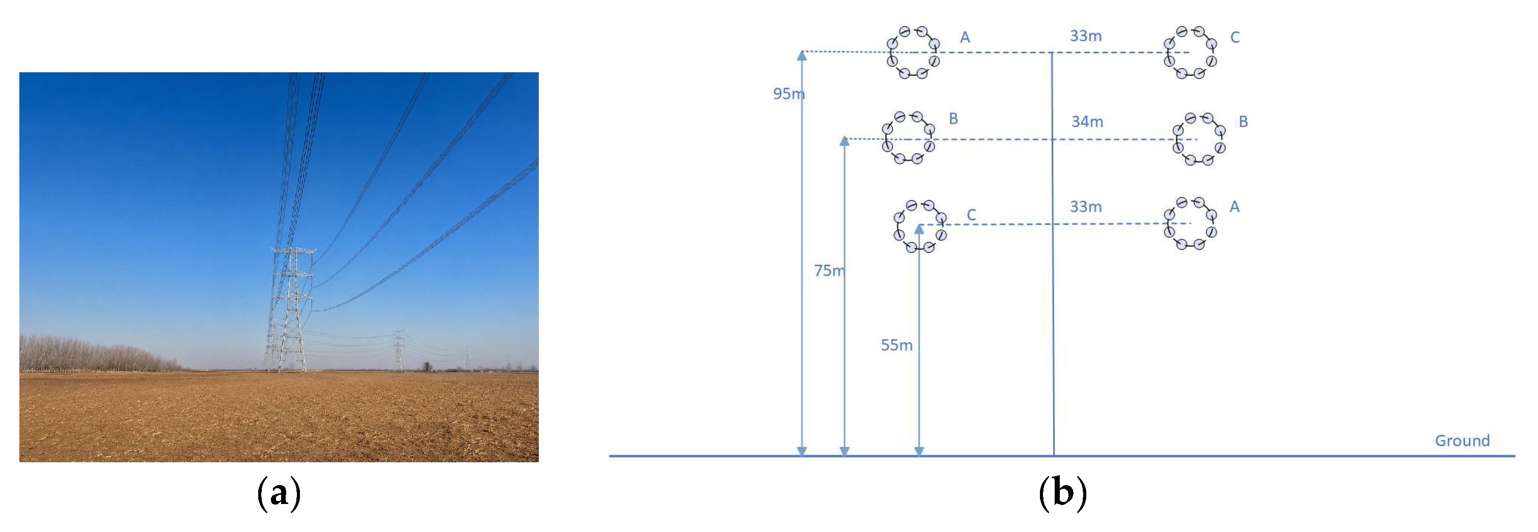
The UHV AC transmission line selected in this study is the 1000 kV Ding–Tai double-circuit transmission line. The span length is 625 m, and the conductor is configured as an 8 × LGJ-630/45 bundle. The rated voltage is 1000 kV. The line adopts a drum-type arrangement, with conductor heights of 95 m, 75 m, and 55 m above ground level for the upper, middle, and lower phases, respectively. The lowest point of the transmission line is approximately 30 m above the ground. The phase spacings from top to bottom are 33 m, 34 m, and 33 m, respectively. The phases are arranged in reverse sequence. In Figure 1b, A, B, and C denote the three phases of the transmission line. The detailed conductor arrangement and phase sequence are shown in Figure 1.
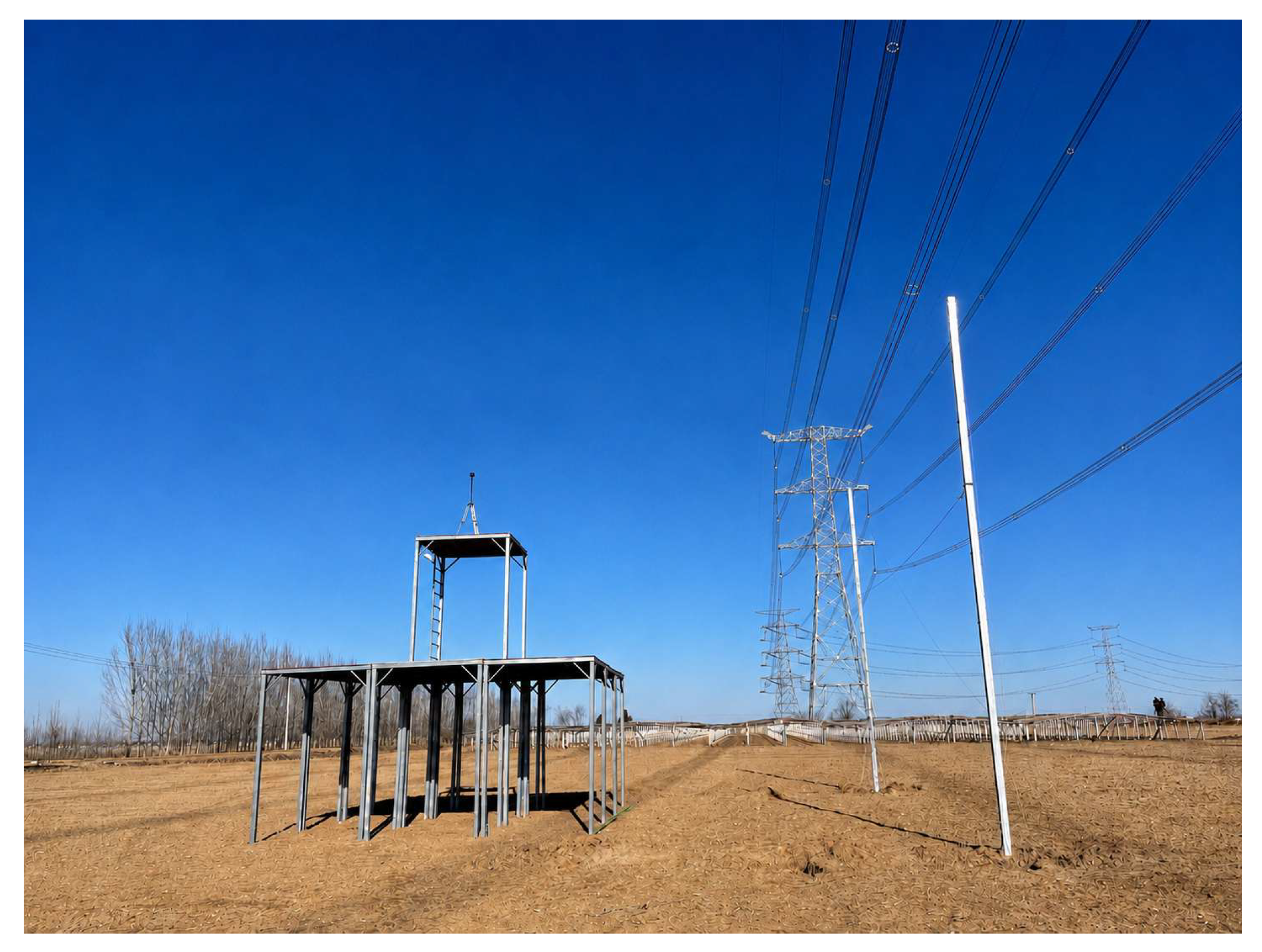
The photograph of the experimental model is shown in Figure 2. The steel pipes used to construct the house model had a square cross-section of 10 cm × 10 cm. The first floor was 6 m long, 6 m wide, and 3 m high, while the second floor was 2 m long, 2 m wide, and 3 m high. The second-floor platform was detachable. With the second-floor platform installed, the total height of the house was 6 m, hereafter referred to as the two-story platform. After the platform was removed, the height was 3 m, hereafter referred to as the single-story platform. In this study, measurements were conducted for both the single-story platform and the two-story platform.
The shielding poles had a square base of 20 cm × 20 cm and a height of 8 m. The shielding wires could be suspended at heights of 4 m, 5 m, 6 m, and 7 m, and each shielding wire had a diameter of 5 mm.
A Narda EFA300 (Narda Safety Test Solutions GmbH, Pfullingen, Germany) field analyzer was used for measurement. The typical broadband measurement uncertainty was ±3% for field strengths of ≥5 V/m within the frequency range of 5 Hz–2 kHz.

3. Analysis of Electric Field Measurement Results

All power-frequency electric field measurements were conducted under weather conditions without rain or snow and with a relative humidity of less than 60%. The measurement points were located at a height of 1.5 m above the ground or the platform.

3.1. Power-Frequency Electric Field in the Cross-Section Perpendicular to the Transmission Line

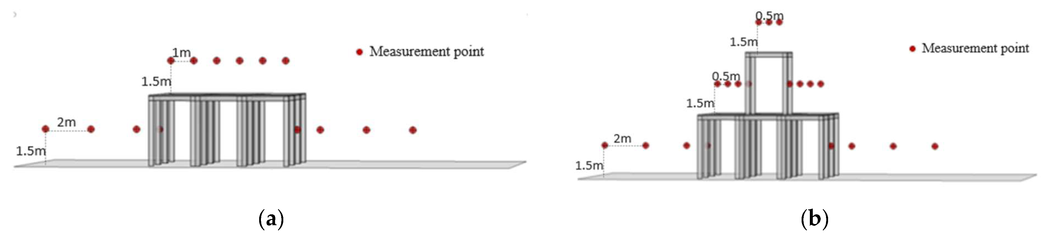
The cross-sectional measurement positions are shown in Figure 3. Because this study focuses on the electric field distribution around houses, the measurements started directly beneath the side-phase conductor, corresponding to a horizontal distance of 16.5 m from the transmission-line centerline. From this position, the measurement points were arranged along the direction perpendicular to the transmission line at intervals of 2 m on the ground, 1 m on the single-story platform, and 0.5 m on the two-story platform.
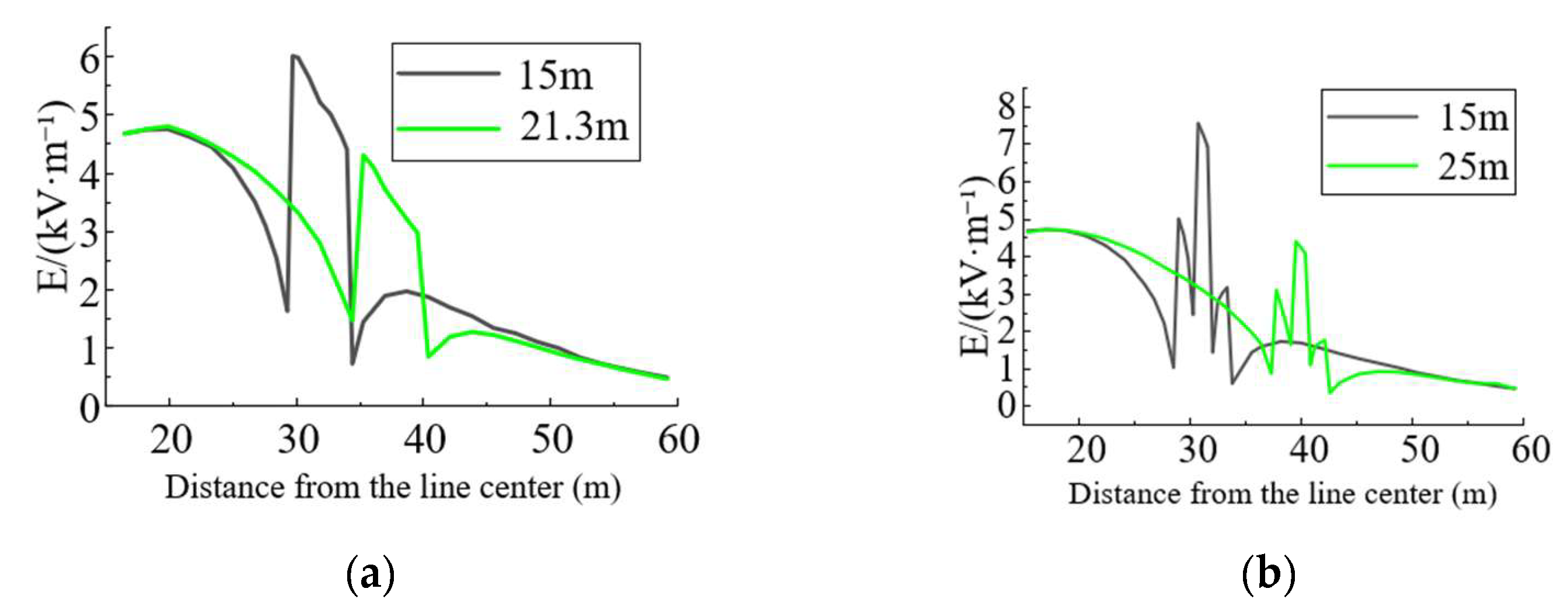
The cross-sectional electric fields were measured for the single-story platform at edge-to-line distances of 15 m and 21.3 m, and for the two-story platform at edge-to-line distances of 15 m and 25 m. The results are shown in Figure 4.
As the distance between the house and the transmission line increases, the electric field above the platform decreases significantly. At ground positions close to the house, the power-frequency electric field decreases to some extent because of the shielding effect of the house. In contrast, the electric field above the platform increases markedly owing to the greater height. The average electric field above the two-story platform is approximately 40% higher than that above the single-story platform.

3.2. Electric Field Around the House

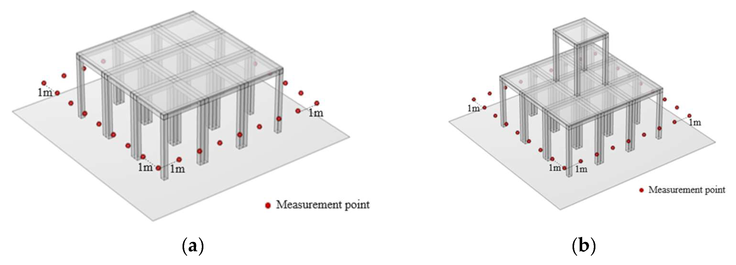
The measurement points around the house are shown in Figure 5. Measurement points were arranged at intervals of 1 m at selected distances from the house.
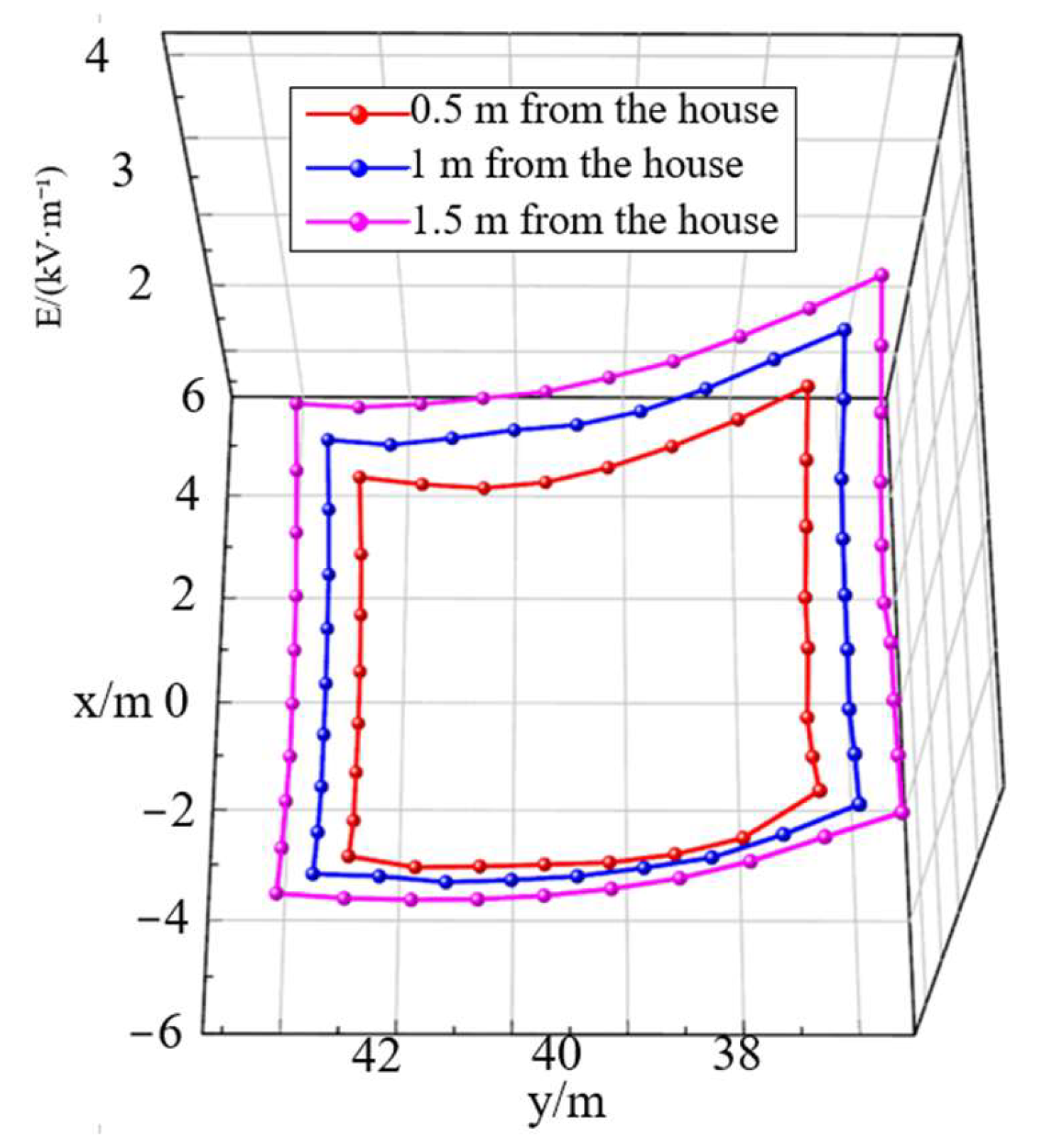
When the edge of the house was 21.3 m from the transmission line, the electric field intensities at distances of 0.5 m, 1 m, and 1.5 m outside the platform edge were measured. The results are shown in Figure 6.
Owing to the distortion effect, the electric field intensity was relatively high near the two corners close to the transmission line. Although the electric field intensity at the two corners on the side away from the transmission line also increased slightly, it remained lower due to the shielding effect of the house. The electric field intensity at the measurement points on the side close to the conductor was approximately 2.4 kV/m, whereas that on the side away from the conductor was only about 1 kV/m because of the shielding effect of the house. Meanwhile, due to the shielding effect of the house, within the range of 0.5–1.5 m from the house, the electric field intensity decreased as the distance from the house decreased. The average electric field at a distance of 0.5 m from the house was 22.7% lower than that at a distance of 1.5 m.
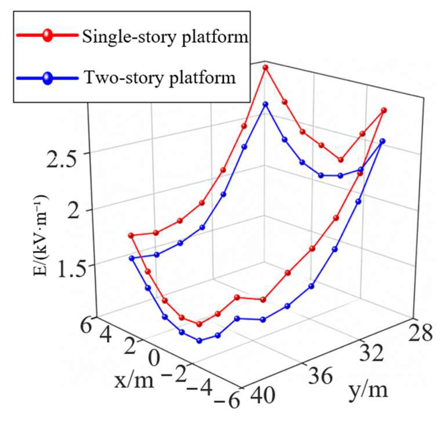
When the platform was 15 m from the side-phase conductor, the electric fields at a distance of 1.5 m around the single-story platform and the two-story platform were measured. The measurement results are shown in Figure 7.
Similarly, the electric field intensity on the side close to the transmission line is significantly higher than that on the side away from the transmission line. In addition, the higher two-story platform provides a more pronounced shielding effect on the ground electric field near the platform. Compared with the single-story platform, the ground electric field intensity near the two-story platform decreases by approximately an additional 10%.

3.3. Electric Field Above the Platform

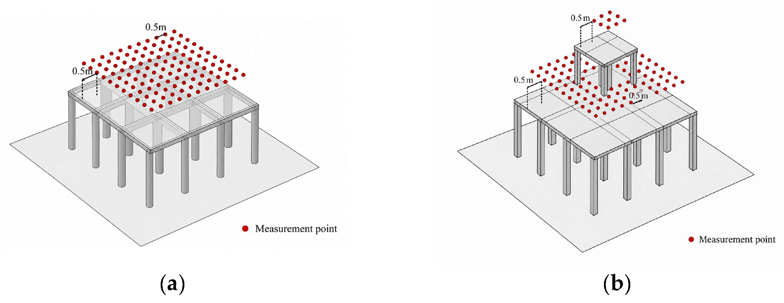
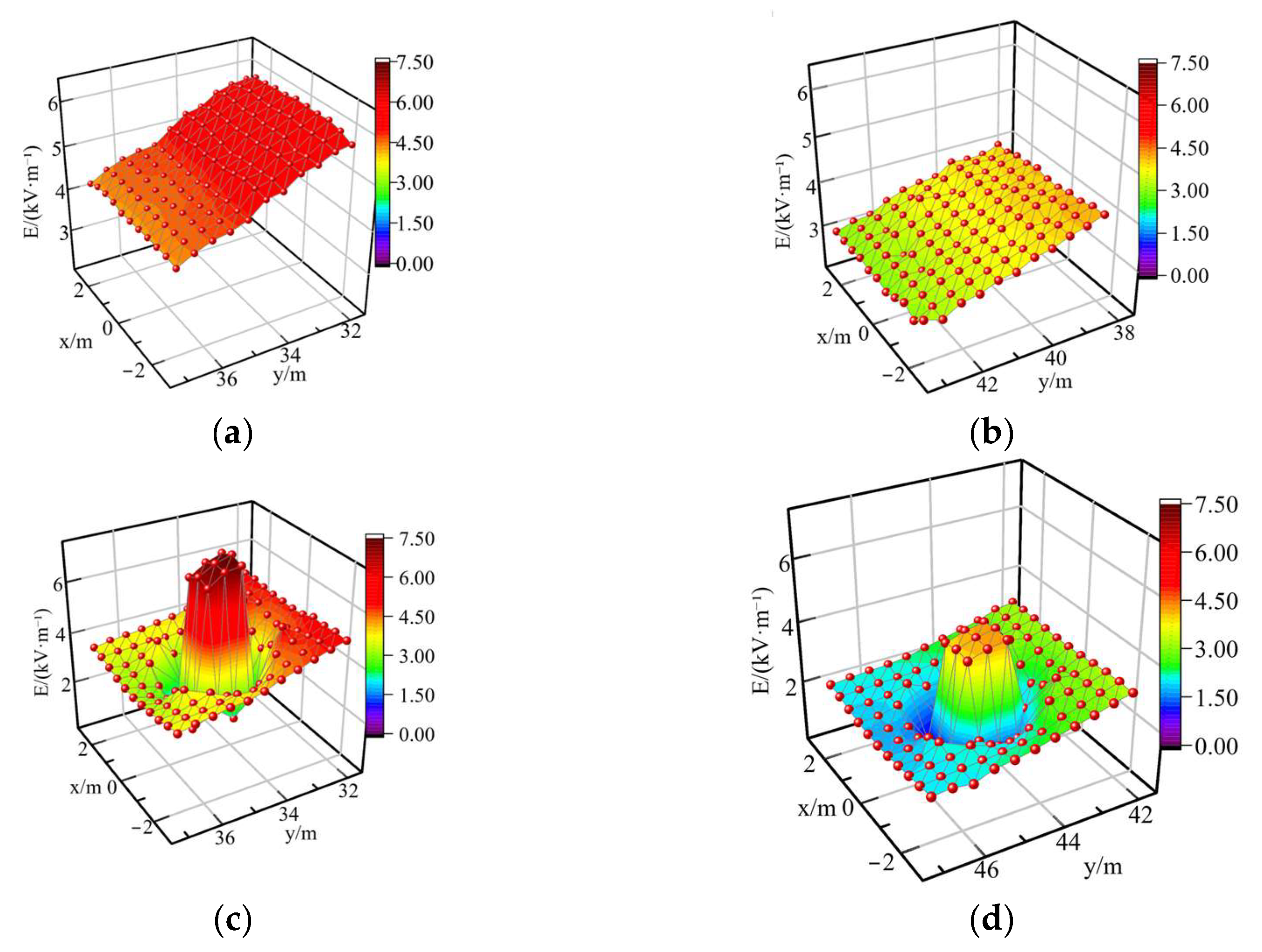
Measurement points were arranged at intervals of 0.5 m above the platform, and the shortest distance between each measurement point and the platform edge was 0.5 m, as shown in Figure 8.
The electric fields above the single-story platform at distances of 15 m and 21.3 m from the side-phase conductor, and those above the 6 m two-story platform at distances of 15 m and 25 m from the side-phase conductor, were measured. The results are shown in Figure 9.
The electric field intensity above the platform shows an approximately linear distribution in the direction perpendicular to the transmission line. For every 1 m increase in the perpendicular distance, the electric field decreases by about 5%. In the direction parallel to the transmission line, the electric field intensity remains almost unchanged. The two-story platform has a certain shielding effect on the electric field of the first-floor platform, reducing the maximum electric field on the first-floor platform by approximately 15%.

4. Analysis of the Effect of Shielding Measures

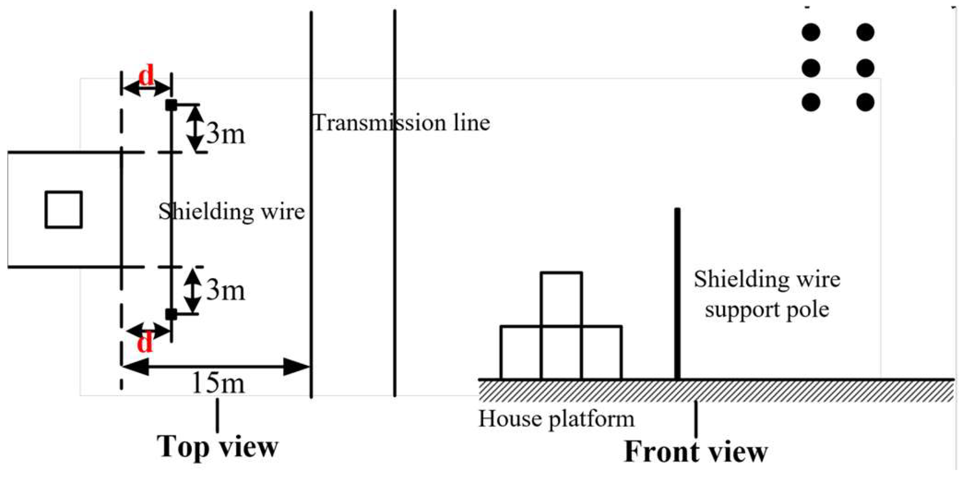
For houses near existing transmission lines, the platform electric field cannot be controlled by increasing the distance between the house and the line. Therefore, it is necessary to investigate the shielding effect of installing shielding wires on the platform electric field. In this study, the shielding effect on the power-frequency electric field was investigated under the condition with the maximum platform electric field, namely the two-story platform with its edge 15 m from the transmission line. The positions of the transmission line, platform, and shielding wires are shown in Figure 10.
The support poles were kept 3 m from the edge of the house platform in the direction parallel to the transmission line, while the distance d from the platform edge in the direction perpendicular to the transmission line was set to 0 m, 3 m, and 6 m for investigation.
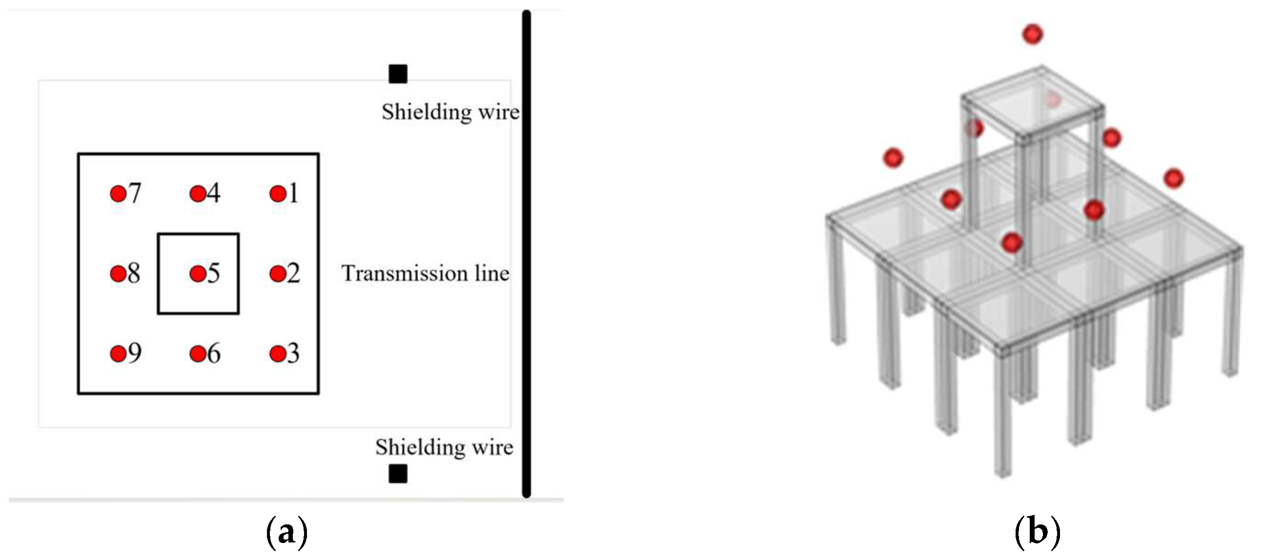
The measurement points for the power-frequency electric field under different shielding wire arrangements are shown in Figure 11, where numbers 1–9 represent the corresponding measurement points.

4.1. Effect of the Distance Between the Shielding Wire and the House on the Shielding Performance

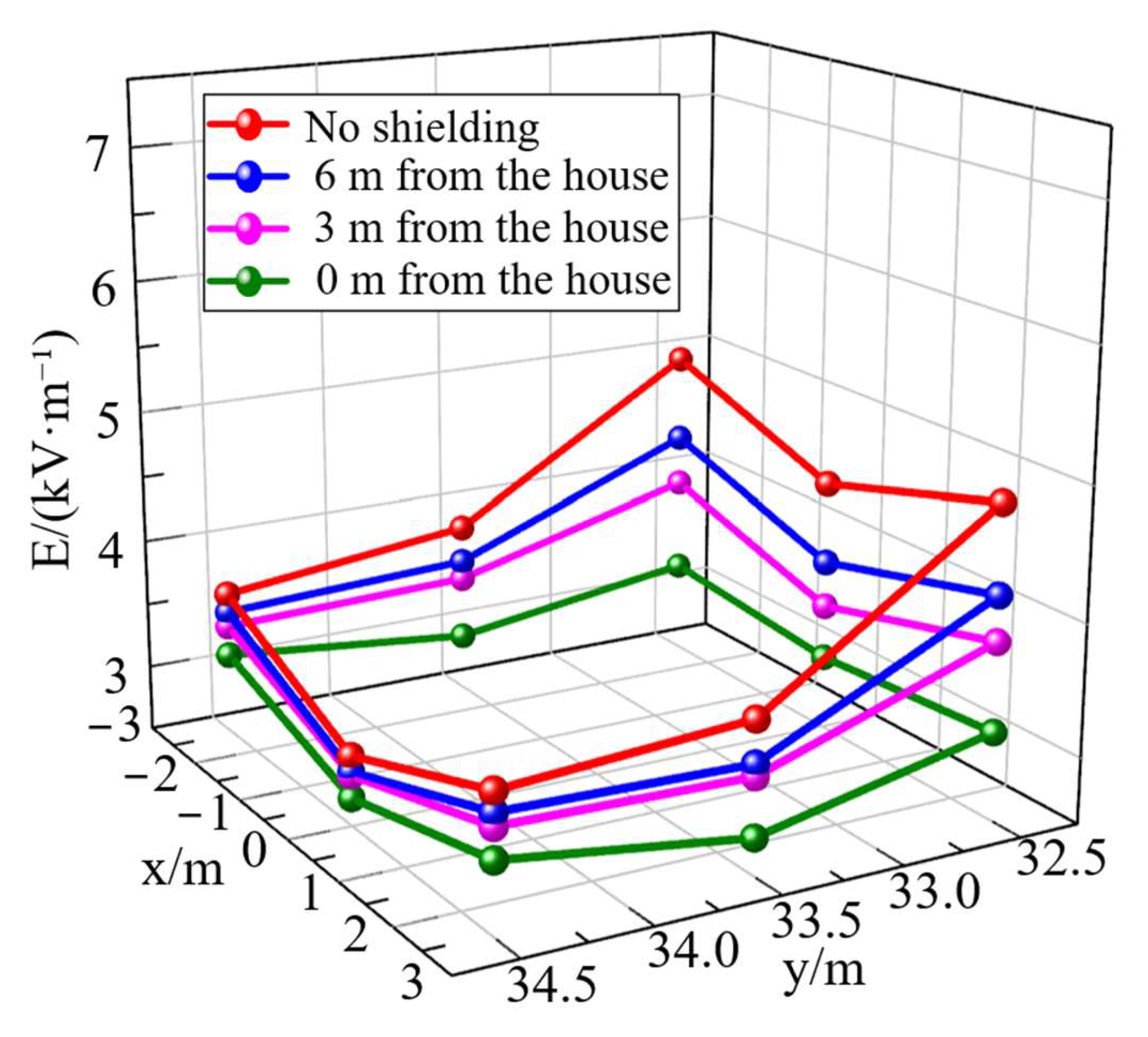
When the shielding wire was suspended at a height of 7 m, the distance d between the shielding wire and the edge of the house was set to 0 m, 3 m, and 6 m. The electric fields at the measurement points on the two-story platform are shown in Figure 12.
The electric field values at measurement point 5 on the two-story platform, measurement point 1 on the first-floor platform, where the electric field was the highest among the first-floor platform points, and measurement point 8 on the first-floor platform, where the electric field was the lowest among the first-floor platform points, are listed in Table 1.
By comparing the power-frequency electric fields on the platform when the distance between the shielding wire and the house was 0 m, 3 m, and 6 m, it can be seen that the shielding effect improved as the shielding wire was placed closer to the house. When the shielding wire was 0 m from the house, the electric field at measurement point 1 decreased by 35.1%. When the distance was 6 m, the electric field at measurement point 1 decreased by 13.2%.
A comparison of the electric field intensities at measurement points 1, 2, and 3 with those at measurement points 7, 8, and 9 shows that the shielding wire had a better shielding effect on the points closer to it. When the shielding wire was 0 m from the house, the average electric field at measurement points 1, 2, and 3 decreased by 34.2%, whereas that at measurement points 7, 8, and 9 decreased by 13.7%.

4.2. Effect of Shielding Wire Height on the Shielding Performance

When the shielding wire was 3 m from the edge of the house, a single shielding wire was suspended at heights of 4 m, 5 m, 6 m, and 7 m. The measured electric field values at typical points are listed in Table 2.
For the first-floor platform, the shielding wire at a height of 4 m showed the weakest shielding effect, and the electric field at measurement point 1 decreased by 16.8%. The shielding effects of the shielding wires at heights of 6 m and 7 m were basically the same, and the electric field at measurement point 1 decreased by 20.4%. This is because the height of the first-floor measurement point was 4.5 m. When the shielding wire was lower than the measurement point, the shielding effect was weakened. When the shielding wire was 1–2 m higher than the measurement point, a better shielding effect was achieved. Further increasing the height of the shielding wire did not lead to a significant improvement.
For the two-story platform, the shielding wire at a height of 7 m provided the best shielding effect, with the electric field decreasing by 6.5%. The shielding effects at the other three heights were relatively weak. This is also because the height of the measurement point on the two-story platform was 7.5 m. When the shielding wire was too low, its shielding effect on the electric field at this position was limited.

4.3. Effect of Multiple Shielding Wires on the Shielding Performance

The shielding effect under multiple shielding wires was compared at the position where the shielding wires were 3 m from the edge of the house platform. Four shielding wire arrangements were tested: shielding wires suspended at heights of 5 m and 6 m, 5 m and 7 m, 6 m and 7 m, and 5 m, 6 m, and 7 m. The electric fields on the platform were measured under these conditions. The electric field values at measurement points 5, 1, and 8 are listed in Table 3.
For the first-floor platform, the arrangement with three shielding wires suspended at heights of 5 m, 6 m, and 7 m provided the best shielding effect. The electric field intensity on the side of the first-floor platform close to the transmission line decreased by 25–30%. The shielding effect of two shielding wires was better than that of a single shielding wire. For the two-story platform, the three-wire arrangement also provided the best shielding effect. However, the arrangement with shielding wires suspended at heights of 5 m and 6 m showed a weaker shielding effect than a single shielding wire at a height of 7 m.
In summary, multiple shielding wires provide a better shielding effect, and three shielding wires can significantly reduce the electric field. When multiple shielding wires are used, their suspension height should be properly ensured. If the shielding wires are much lower than the measurement points, the shielding effect is very limited, and using a single shielding wire at a greater height is more effective.

4.4. Surface Electric Field on the Platform After Shielding

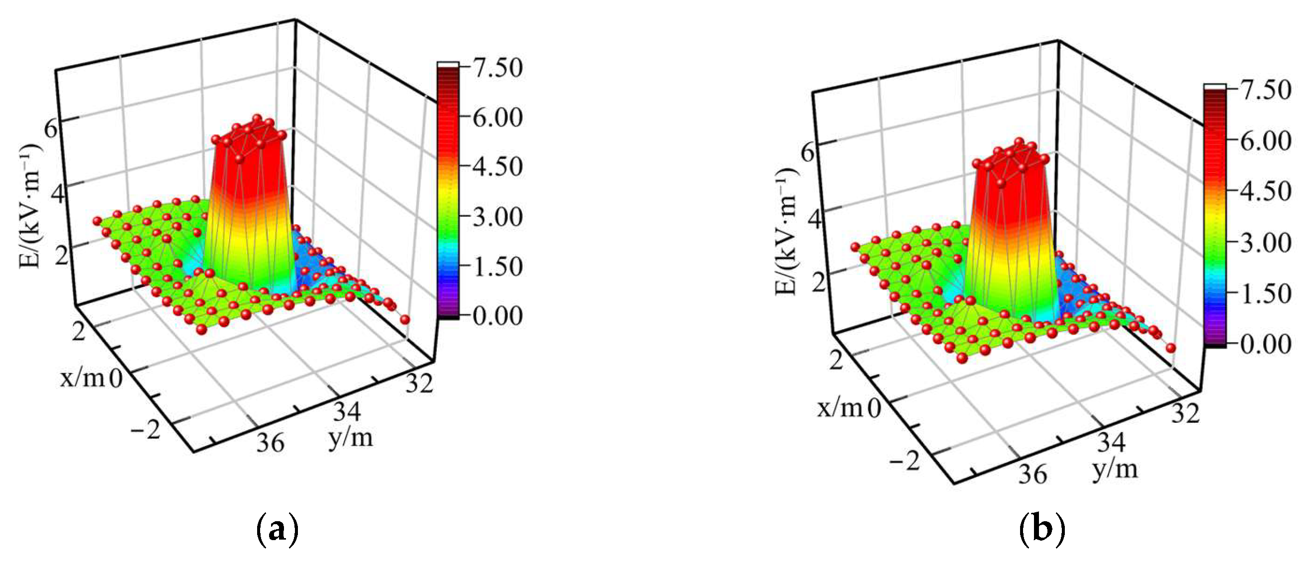
To evaluate the shielding effect over the entire platform surface, the electric field on the upper surface of the platform was measured when the shielding wires were 0 m and 3 m from the edge of the house, with wires suspended at heights of 5 m, 6 m, and 7 m. The measured electric field intensities are shown in Figure 13.
Figure 13 more clearly shows the shielding effect of the shielding wires on the electric field. Compared with Figure 9c, the electric field was significantly reduced after the shielding wires were installed. In particular, when the shielding wires were installed at 0 m, the electric field intensity at measurement point 5 on the two-story platform decreased from 7.31 kV/m under the unshielded condition to approximately 6.14 kV/m after shielding, corresponding to a reduction of approximately 16%. For the first-floor platform, the shielding effect of the shielding wires made the electric field on the side close to the transmission line lower than that on the side away from the transmission line.

5. Simulation

Based on the electric field distribution characteristics of the house obtained from the experiments, the finite element method was used to further calculate additional parameters. On this basis, an installation scheme involving the diameter, length, height, and combination of shielding wires was proposed.

5.1. Establishment of the Calculation Model

The power-frequency electric field generated when the transmission line is energized can be regarded as an electrostatic field. Therefore, when calculating the electric field on the platform of a nearby house, an electrostatic field model can be established, with the potential of the house set to zero. The governing equations of the electrostatic field are as follows:
× E = 0
D = ρ
E = φ
where E is the electric field intensity, D is the electric displacement vector, ρ is the volume charge density, which is assumed to be zero in the air domain in this study, and φ is the electric potential.
Since the voltage on the transmission line and the ground potential are known, the boundary conditions satisfy the Dirichlet boundary condition:
φ S = φ 0
where S is the calculation domain, and φ0 is the potential on the boundary.
The electrostatic variational equation is expressed as follows:
S ε 2 φ x 2 + φ y 2 + φ z 2 ρ φ d x d y d z = W e = S 1 2 ε E 2 d V = W e min
φ L i = φ i ( r b ) ( i = 1 , 2 n )
where We is the total energy of the electrostatic system, ε is the permittivity, Li is the i-th boundary, φi(rb) is the known potential at point rb on the i-th boundary, and x, y, and z denote the coordinate system.
Based on the above calculation method, the potentials of the ground and the house surface were set to zero. The potentials assigned to the three-phase conductors are expressed as follows:
U a = 1.05 3 U U b = 1.05 3 U e j 2 π 3 U c = 1.05 3 U e j 2 π 3
where U is 1000 kV.
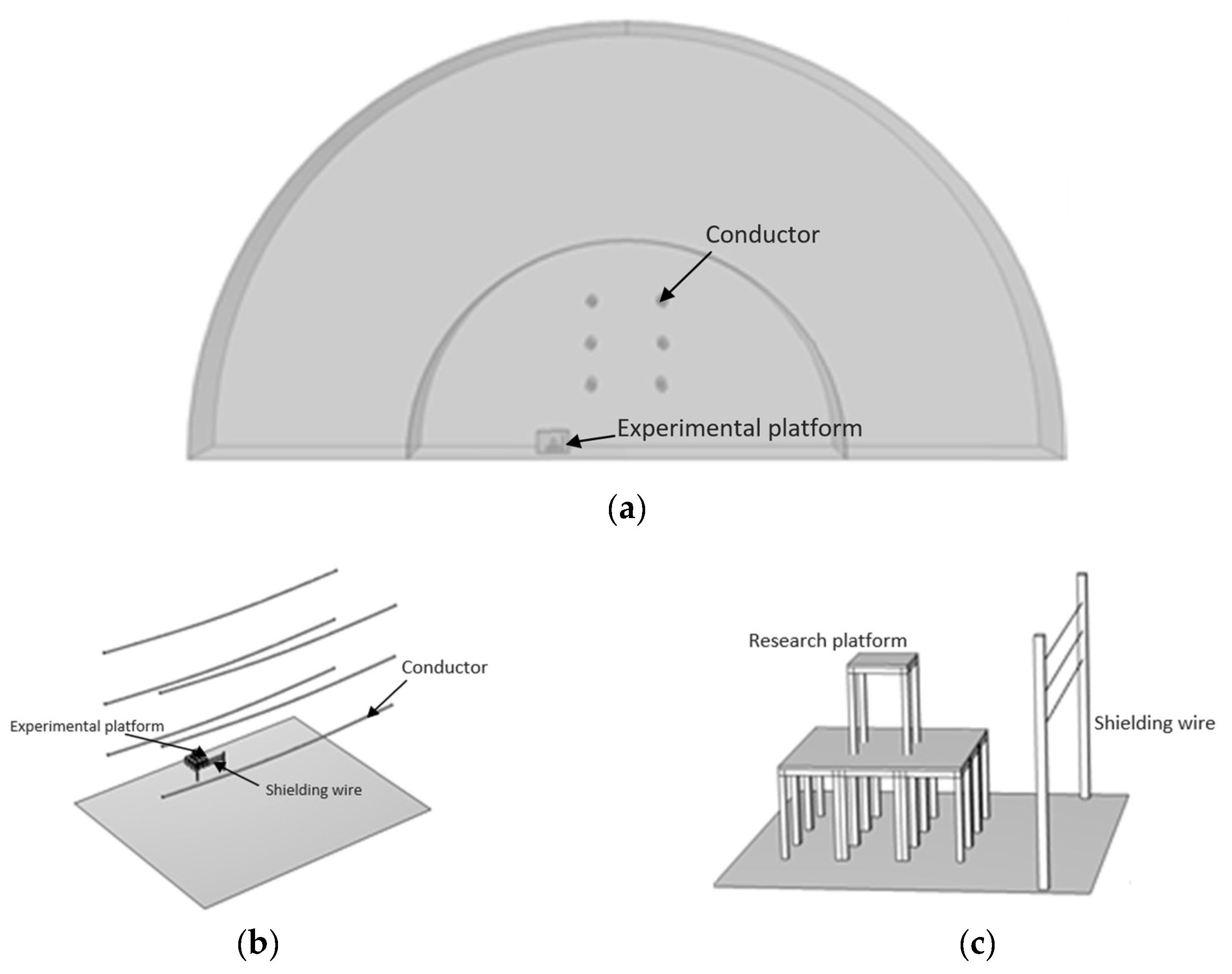
The simulation model reproduced the structure of the experimental model, as shown in Figure 14. The transmission line was modeled with an equivalent radius of 0.442 m, and the middle 100 m section was selected as the modeling segment. The other parameters remained unchanged.

5.2. Verification of Simulation Results

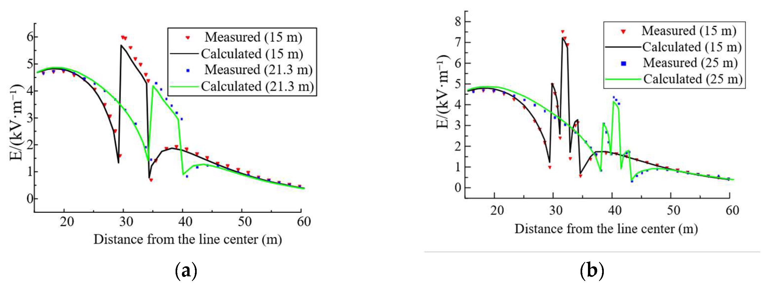
Without shielding wires installed, the measured and calculated cross-sectional electric fields were compared for the 3 m house at distances of 15 m and 21.3 m from the side-phase conductor, and for the 6 m house at distances of 15 m and 25 m from the side-phase conductor. The comparison results are shown in Figure 15.
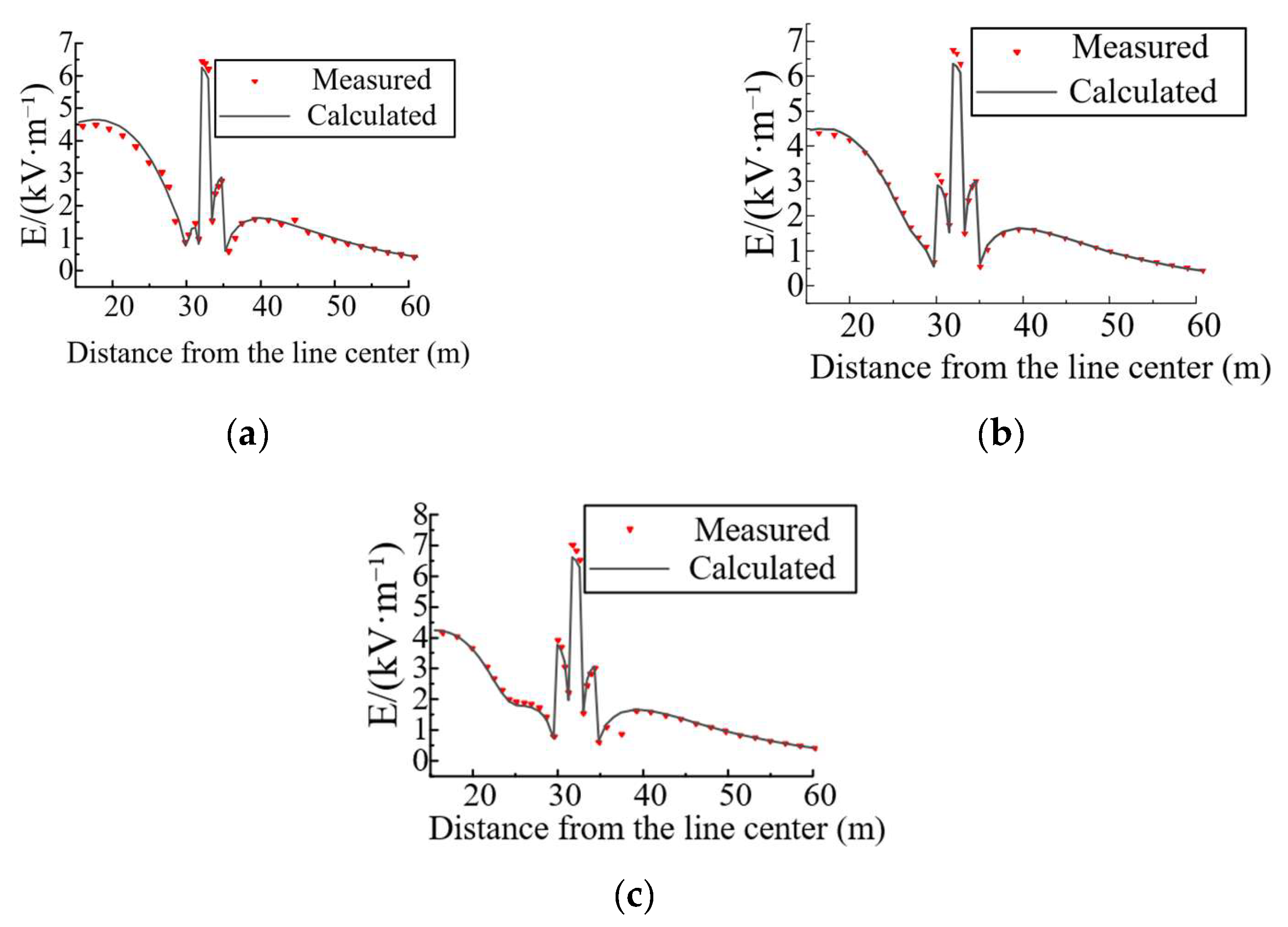
With three shielding wires installed at heights of 5 m, 6 m, and 7 m, the measured and calculated platform electric fields were compared for cases in which the shielding wires were located 0 m, 3 m, and 6 m from the edge of the house. The comparison results are shown in Figure 16.
Before shielding, the overall errors between the measured and calculated electric fields of houses at different heights and locations were within 10%, and the maximum error at the sensitive point, namely the position with the maximum electric field, was 4.7%. After shielding, the overall errors were also within 10%, and the maximum error at the sensitive point was 5.3%. Under the above conditions, the measured values agreed well with the calculated values, indicating that the calculation results have relatively high accuracy and can be applied in engineering practice.

5.3. Discussion on the Optimal Shielding Method

Under the conditions of a tower height of 30 m, a house height of 6 m, a distance of 15 m between the house edge and the transmission line, a distance of 0 m between the shielding wire and the house, and a shielding wire height of 9 m, the effects of shielding wire diameter, length, height, and combination on the electric field were investigated.
  • Shielding wire diameter;
Cases with shielding wire diameters of 1 mm, 5 mm, and 10 mm were calculated. The shielding effect of the 10 mm diameter shielding wire was 4.1% better than that of the 1 mm diameter shielding wire and 1.3% better than that of the 5 mm diameter shielding wire. This indicates that increasing the shielding wire diameter has only a limited effect on improving the shielding performance. Considering the tensile force borne by the shielding poles and the cost of the shielding wire itself, a relatively thin type among commonly used shielding wires can be selected for installation.
2.
Shielding wire length;
Shielding wire lengths of 6 m and 12 m were calculated. The results show that the shielding wire length mainly affects the shielding range and has only a slight influence on the shielding effect. The shielding effect of the 12 m shielding wire was 3.9% better than that of the 6 m shielding wire. Therefore, the shielding wire does not need to be excessively long. It is sufficient to ensure that each side of the shielding wire extends 1.5 m beyond the edge of the house, namely that the total length is 3 m longer than the house edge.
3.
Shielding wire height;
In the experiment in Section 3.2, the shielding effects of a single shielding wire at heights of 6 m and 7 m on point 1 were close, indicating that the shielding wire can provide a good shielding effect within a certain height range. Considering that the cost of shielding wire installation increases significantly as the installation height increases in engineering practice, attention should be paid not only to the optimal height hopt corresponding to the best shielding effect, but also to the lower height limit hmin at which the shielding effect is close to the optimal value.
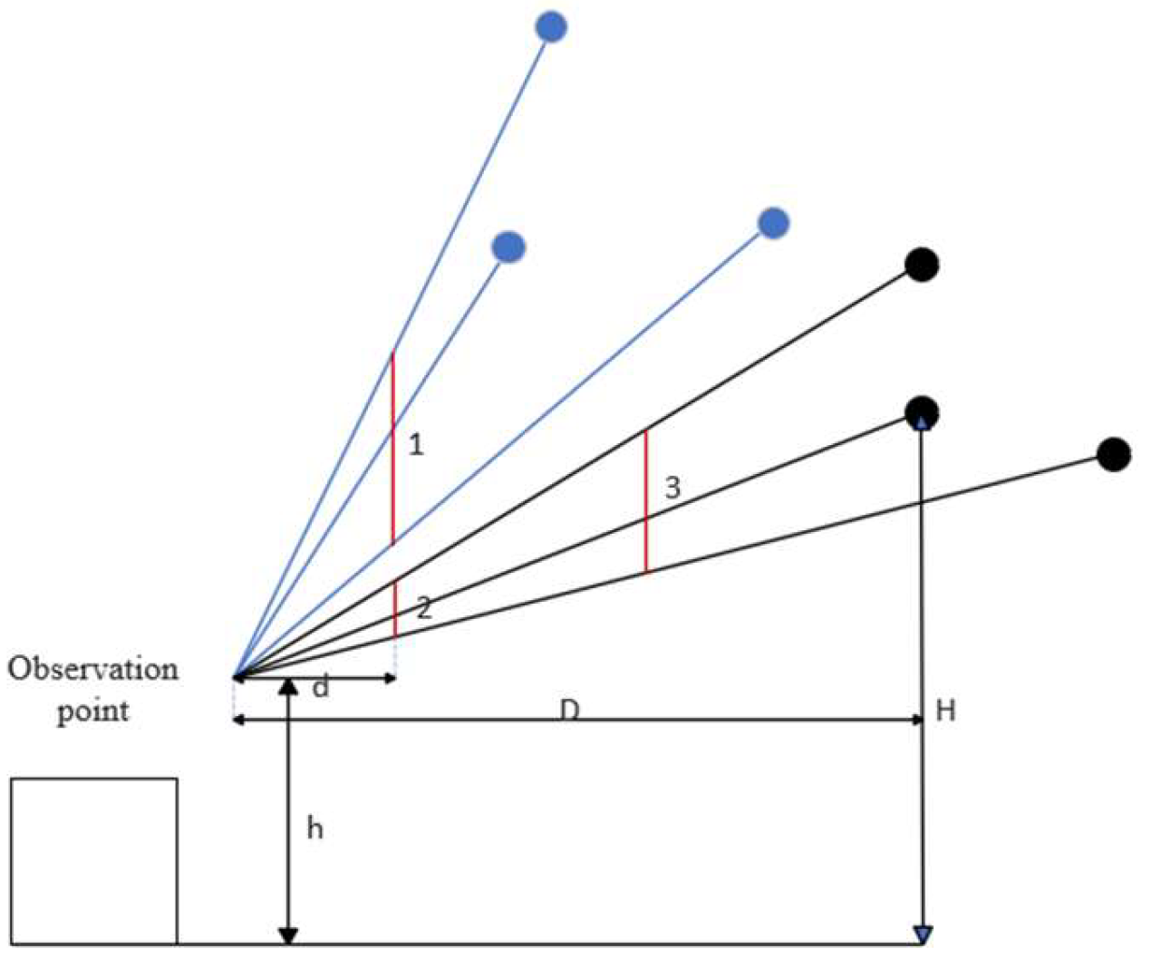
As shown in Figure 17, the electric field at the observation point mainly comes from the three conductors closest to the house. H is the tower height, h is the height of the measurement point, D is the distance between the transmission line and the measurement point, and d is the distance between the shielding wire and the measurement point.
The shielding effect is the best when the shielding wire is located on the connection lines between these three conductors and the observation point, as indicated by the red line segments. According to the principle of similar triangles, the value of (H-h)/D affects the optimal shielding height, as shown by lines 1 and 2, while the shielding wire distance d also affects the optimal shielding height range, as shown by lines 2 and 3.
Calculations were performed for six cases with tower heights of 30 m, 33 m, and 36 m, a house height of 6 m, and distances of 15 m and 20 m between the house edge and the transmission line. The results show that when the shielding wire was 0 m from the house, the optimal shielding wire height hopt was 2–3 m higher than the measurement point. As the distance d between the shielding wire and the house increased, hopt increased continuously, while the shielding effect decreased. When the shielding wire was 1.5 m higher than the measurement point, the difference between the shielding effect at this height and that at the optimal height was within 0.2 kV/m.
4.
Combination of multiple shielding wires;
When multiple shielding wires are used, their suspension height should first be ensured. The shielding wires should be suspended upward successively from a position 1.5 m higher than the measurement point. If the available suspension height is limited, the wires should be suspended downward from the highest available position, and the lowest wire should not be lower than 1.5 m above the measurement point.
In addition, the spacing between shielding wires should be ensured. Compared with a single shielding wire suspended at a height of 9 m, the shielding effect was improved by 4.2% when shielding wires were suspended at heights of 9 m and 9.1 m, by 6.9% when suspended at 9 m and 9.5 m, and by 8.5% when suspended at 9 m and 10 m. When the spacing between shielding wires is too small, part of the shielding effect overlaps, and the effect of multiple shielding wires cannot be fully utilized. When the spacing is too large, the upper shielding wire becomes excessively high. Therefore, a spacing of 1 m is relatively suitable when multiple shielding wires are used.
In the experiment, the use of three shielding wires produced a significant shielding effect, but it also generated a relatively large tensile force. Further increasing the number of shielding wires caused obvious inclination of the support poles. Therefore, unless otherwise required, two or three shielding wires are sufficient for multiple-wire shielding.

6. Conclusions

  • Before and after the installation of shielding wires, the measured and calculated electric fields on the house platform agreed well under various conditions. This indicates that the finite element simulation model can calculate the electric field on the house platform with relatively high accuracy and can provide a reference for practical engineering construction.
  • The house itself has a shielding effect on the surrounding electric field. At the edges and corners of the house, electric field distortion occurs to a certain extent, resulting in a higher electric field at these positions than at other locations.
  • According to the electromagnetic environment requirements for residential areas in China, the recommended power-frequency electric field limit for houses is 4 kV/m. The results indicate that shielding wires can effectively reduce the electric field intensity in areas with relatively high electric field levels on house platforms, providing an effective approach for improving the electric field environment of houses near 1000 kV UHV AC transmission lines.
  • The closer the shielding wire is to the house, the better the shielding effect. A shielding wire length 3 m longer than the house edge and a height 1.5 m higher than the position to be shielded can achieve a relatively optimal balance between shielding performance and installation economy. When multiple shielding wires are used, their installation heights should be at least 1.5 m higher than the shielding point where possible, and a spacing of 1 m should be maintained between adjacent shielding wires.

Author Contributions

Conceptualization, H.D. and W.H.; methodology, H.D.; software, W.Y.; validation, X.H., J.C. and J.X.; formal analysis, W.Y.; investigation, H.D.; resources, H.D.; data curation, F.L.; writing—original draft preparation, H.D.; writing—review and editing, W.H.; visualization, L.T.; supervision, W.Y.; project administration, J.Y.; funding acquisition, C.J. All authors have read and agreed to the published version of the manuscript.

Funding

This work was supported by the Science and Technology Project of State Grid Anhui Electric Power Co., Ltd., “Research on Accurate Prediction and Prevention Technology for Transient Electric Shock Induced by Electric Fields of EHV/UHV AC and DC Transmission Lines” under Project No. 52120525000L.

Institutional Review Board Statement

Not applicable.

Informed Consent Statement

Not applicable.

Data Availability Statement

The datasets presented in this article are not readily available because the research project has not been finalized and the relevant original data is under confidential management. Requests to access the datasets should be directed to the corresponding author.

Acknowledgments

The authors sincerely thank Lunan Xu for her great support and valuable contribution to this research. This study was completed with her assistance and support.

Conflicts of Interest

The authors declare that this study received funding from Science and Technology Project of State Grid Anhui Electric Power Co., Ltd. The funder was not involved in the study design, collection, analysis, interpretation of data, the writing of this article or the decision to submit it for publication.

References

  1. Shu, Y.; Zhang, W. Research of key technologies for UHV transmission. Proc. CSEE 2007, 27, 1–6. [Google Scholar] [CrossRef]
  2. Shu, Y.; Hu, Y. Research and application of the key technologies of UHV AC transmission line. Proc. CSEE 2007, 27, 1–7. [Google Scholar] [CrossRef]
  3. Caola, R.J., Jr.; Deno, D.W.; Dymek, V.S.W. Measurements of electric and magnetic fields in and around homes near a 500 kV transmission line. IEEE Trans. Power Appar. Syst. 1983, PAS-102, 3338–3347. [Google Scholar]
  4. Deno, D.W. UHV transmission line electric field reduction with a set of horizontal wires. IEEE Trans. Power Appar. Syst. 1977, PAS-96, 1507–1516. [Google Scholar] [CrossRef]
  5. Deno, D.W.; Zaffanella, L.E.; Silva, J.M. Transmission line electric field shielding by objects. IEEE Trans. Power Deliv. 1987, PWRD-2, 269–280. [Google Scholar] [CrossRef]
  6. Hou, Y.; Li, B.; Lu, Z.; Hou, F. Numerical simulation of electric field of high voltage transmission lines based on the real terrains. Chin. J. Radio Sci. 2017, 32, 657–664. [Google Scholar]
  7. Yang, B.; Han, W.; Wu, J.; Wang, S.; Jing, Y.; Wang, L.; Geng, M.; Zhao, Y. Electric Field Distribution in Adjacent Area of Buildings under High Voltage Transmission Line and Its Influencing Factors. Power Grid Anal. Study 2020, 48, 92–96+102. [Google Scholar]
  8. Zhao, Z.; Dong, S.; Xie, H. Distorted electric field of the building near UHVAC double circuit transmission lines on the same tower. High Volt. Eng. 2012, 38, 2171–2177. [Google Scholar]
  9. Yang, B.; Xu, L.; Liu, T. Calculation of Distorted Electric Field for High-Voltage AC Power Transmission Lines Adjacent to Urban High Buildings. South. Power Syst. Technol. 2021, 15, 59–64. [Google Scholar]
  10. Li, Y.; Fan, Y.; Xu, L. Simulation analysis on power frequency electric field at ground surface near EHV power transmission tower. Power Syst. Technol. 2013, 37, 782–787. [Google Scholar]
  11. Zhou, H.; Zuo, P.; Zou, J. Analysis on electromagnetic environment characteristics of high-voltage AC transmission lines passing through complex terrains. Power Syst. Technol. 2011, 35, 164–169. [Google Scholar]
  12. Ryo, N.; Katsumi, N.; Naganori, I. Determining the arrangement of fictitious charges in charge simulation method using genetic algorithms. J. Electrost. 2000, 49, 95–105. [Google Scholar] [CrossRef]
  13. Lee, B.Y.; Myung, S.H.; Min, S.W. An effective modeling method to analyze electric field around transmission lines and substation using a generalized finite line charge. IEEE Trans. Power Deliv. 1997, 12, 1143–1149. [Google Scholar] [CrossRef]
  14. Li, Y.; Wang, Y.; Zou, A. Power-frequency electric field calculation of extra high voltage transmission lines by means of the mixed method combining MOM and SCM. Electr. Mach. Control 2017, 21, 1–8. [Google Scholar]
  15. Pan, Q.; Luo, R.; Tang, X.; Pan, J.; Zhang, X. Analysis on electromagnetic environment of 500 kV doublecircuits on the same tower compact transmission lines. High Volt. Appar. 2017, 53, 183–190. [Google Scholar]
  16. Ye, Q.; Wen, Y.F.; Huang, T.; Zhang, G.Z.; Liu, X.F. Study on the electric field intensity of the UHV AC transmission lines near buildings. High Volt. Appar. 2011, 47, 5–10. [Google Scholar]
  17. Zhang, B.; Cui, X.; Lu, T. A numerical method to calculate three dimensional electric field of EHV transmission line near towers. Power Syst. Technol. 2003, 27, 5–8. [Google Scholar]
  18. Luo, R.; Liu, Z.; Pan, Q. Calculation on power frequency electric field and its protection for 500 kV double-circuit on same tower compact transmission lines. J. Electr. Power 2019, 34, 513–523. [Google Scholar]
  19. Peng, C.; Jiang, L.; Liu, J. Distorted Electric Field Shielding of EHV Transmission Line Based on Extreme Learning Machine Prediction Optimization Model. Power Syst. Technol. 2017, 41, 3655–3662. [Google Scholar]
  20. Tong, Z.; Dong, Z.; Ashton, T. Analysis of electric field influence on buildings under high-voltage transmission lines. IET Sci. Technol. 2016, 10, 253–258. [Google Scholar] [CrossRef]
  21. Wu, G.; Xie, L.; Wang, X.; Zhao, Z. Calculation of Power Frequency Electric Field Around Houses Exposed to Air Near AC Transmission Lines. Power Syst. Technol. 2015, 39, 873–878. [Google Scholar]
  22. Wu, G.; Chen, W.; Mao, J. Study on Limits of Power Frequency Electric Field on House Platform Near AC Transmission Lines. Power Syst. Technol. 2015, 39, 1532–1537. [Google Scholar]
  23. Huang, Z.; Xi, L.; Fan, M.; Zou, P. Improvement of simulation charge setting in calculation of power frequency electric field of high voltage transmission line above buildings. Power Syst. Technol. 2013, 37, 788–793. [Google Scholar]
Figure 1. 1000 kV Ding–Tai UHV AC transmission line. (a) Field photograph; (b) schematic diagram of conductor arrangement and parameters.
Applsci 16 07855 g001
Figure 2. Photograph of the experimental model.
Applsci 16 07855 g002
Figure 3. Cross-sectional arrangement of electric field measurement points. (a) Single-story platform; (b) two-story platform.
Applsci 16 07855 g003
Figure 4. Measured cross-sectional power-frequency electric field distribution. (a) Single-story platform; (b) two-story platform.
Applsci 16 07855 g004
Figure 5. Measurement points around the house. (a) Single-story platform; (b) two-story platform.
Applsci 16 07855 g005
Figure 6. Power-frequency electric field at different distances around the house.
Applsci 16 07855 g006
Figure 7. Power-frequency electric field around the house at different platform heights.
Applsci 16 07855 g007
Figure 8. Measurement points above the house platform. (a) Single-story platform; (b) two-story platform.
Applsci 16 07855 g008
Figure 9. Power-frequency electric fields above house platforms at different locations and heights. (a) Single-story platform, 15 m; (b) single-story platform, 21.3 m; (c) two-story platform, 15 m; (d) two-story platform, 25 m.
Applsci 16 07855 g009
Figure 10. Schematic diagram of the shielding wire arrangement.
Applsci 16 07855 g010
Figure 11. Measurement points with shielding wires installed. (a) Plan view; (b) 3D view.
Applsci 16 07855 g011
Figure 12. Power-frequency electric field at different distances between the shielding wire and the house.
Applsci 16 07855 g012
Figure 13. Power-frequency electric field on the house platform after shielding. (a) d = 0 m; (b) d = 3 m.
Applsci 16 07855 g013
Figure 14. Structure of the simulation model. (a) Overall structure of the simulation model; (b) transmission line structure; (c) house and shielding device structure.
Applsci 16 07855 g014
Figure 15. Cross-sectional electric fields of houses at different locations and heights: (a) 3 m house at 15 m and 21.3 m; (b) 6 m house at 15 m and 25 m.
Applsci 16 07855 g015
Figure 16. Cross-sectional power-frequency electric field of the house after shielding. (a) Shielding wires at 0 m; (b) shielding wires at 3 m; (c) shielding wires at 6 m.
Applsci 16 07855 g016
Figure 17. Optimal height range of the shielding wire.
Applsci 16 07855 g017
Table 1. Electric field at measurement points under different shielding wire distances on the two-story platform.
Shielding Wire ArrangementElectric Field at Point 5/(kV·m−1)Electric Field at Point 1/(kV·m−1)Electric Field at Point 8/(kV·m−1)
No shielding7.314.943.03
Shielding wire 6 m from the house edge6.954.282.91
Shielding wire 3 m from the house edge6.783.902.88
Shielding wire 0 m from the house edge6.293.202.71
Table 2. Electric field at measurement points under different shielding wire heights on the two-story platform.
Shielding Wire ArrangementElectric Field at Point 5/(kV·m−1)Electric Field at Point 1/(kV·m−1)Electric Field at Point 8/(kV·m−1)
No shielding7.314.943.03
4 m shielding wire6.934.112.92
5 m shielding wire6.924.032.91
6 m shielding wire6.903.912.87
7 m shielding wire6.783.902.88
Table 3. Electric field at measurement points under different shielding wire combinations on the two-story platform.
Shielding Wire ArrangementElectric Field at Point 5/(kV·m−1)Electric Field at Point 1/(kV·m−1)Electric Field at Point 8/(kV·m−1)
No shielding7.314.943.03
7 m shielding wire6.783.902.88
5 m and 6 m shielding wires6.853.872.89
5 m and 7 m shielding wires6.683.712.85
6 m and 7 m shielding wires6.653.642.81
5 m, 6 m, and 7 m shielding wires6.623.512.80
Disclaimer/Publisher’s Note: The statements, opinions and data contained in all publications are solely those of the individual author(s) and contributor(s) and not of MDPI and/or the editor(s). MDPI and/or the editor(s) disclaim responsibility for any injury to people or property resulting from any ideas, methods, instructions or products referred to in the content.